FLYTECH TECHNOLOGY P2340000 Handheld POS User Manual manual
FLYTECH TECHNOLOGY CO., LTD Handheld POS manual
UserManual.wiki
>
FLYTECH TECHNOLOGY
>
P2340000 User Manual
manual
Navigation menu
Upload a User Manual
Namespaces
Wiki Guide
HTML
PDF
Info
Views
User Manual
Discussion / Help
Navigation

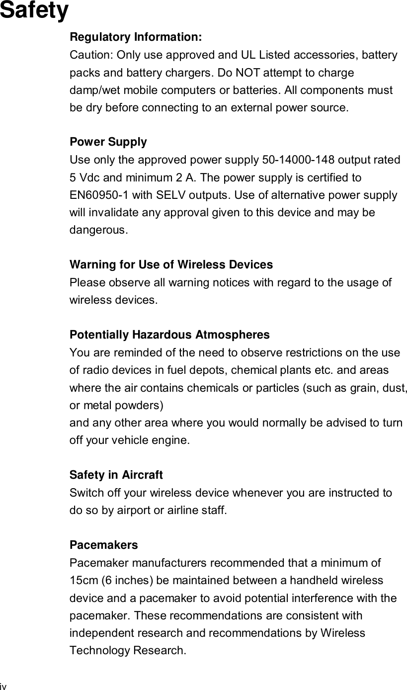

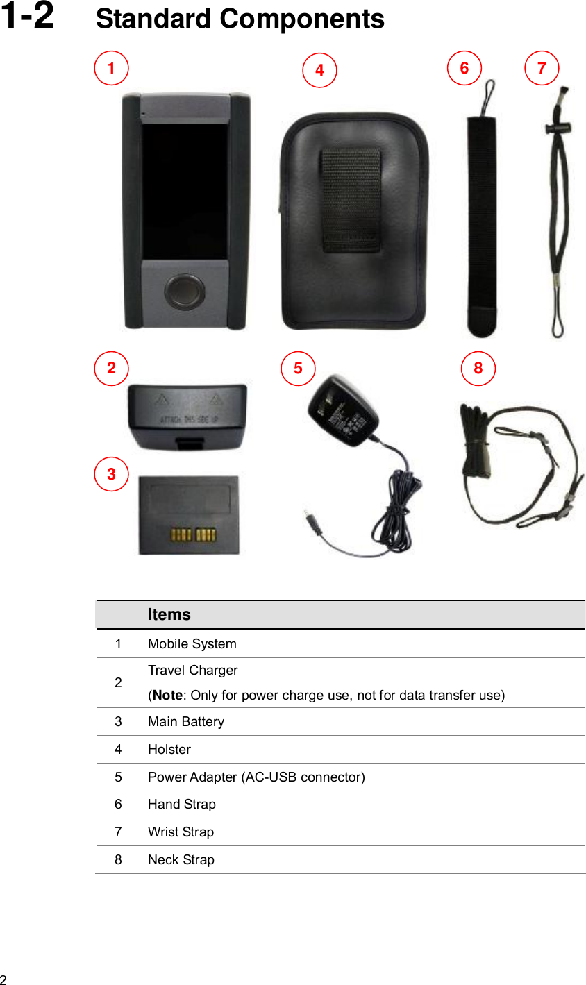

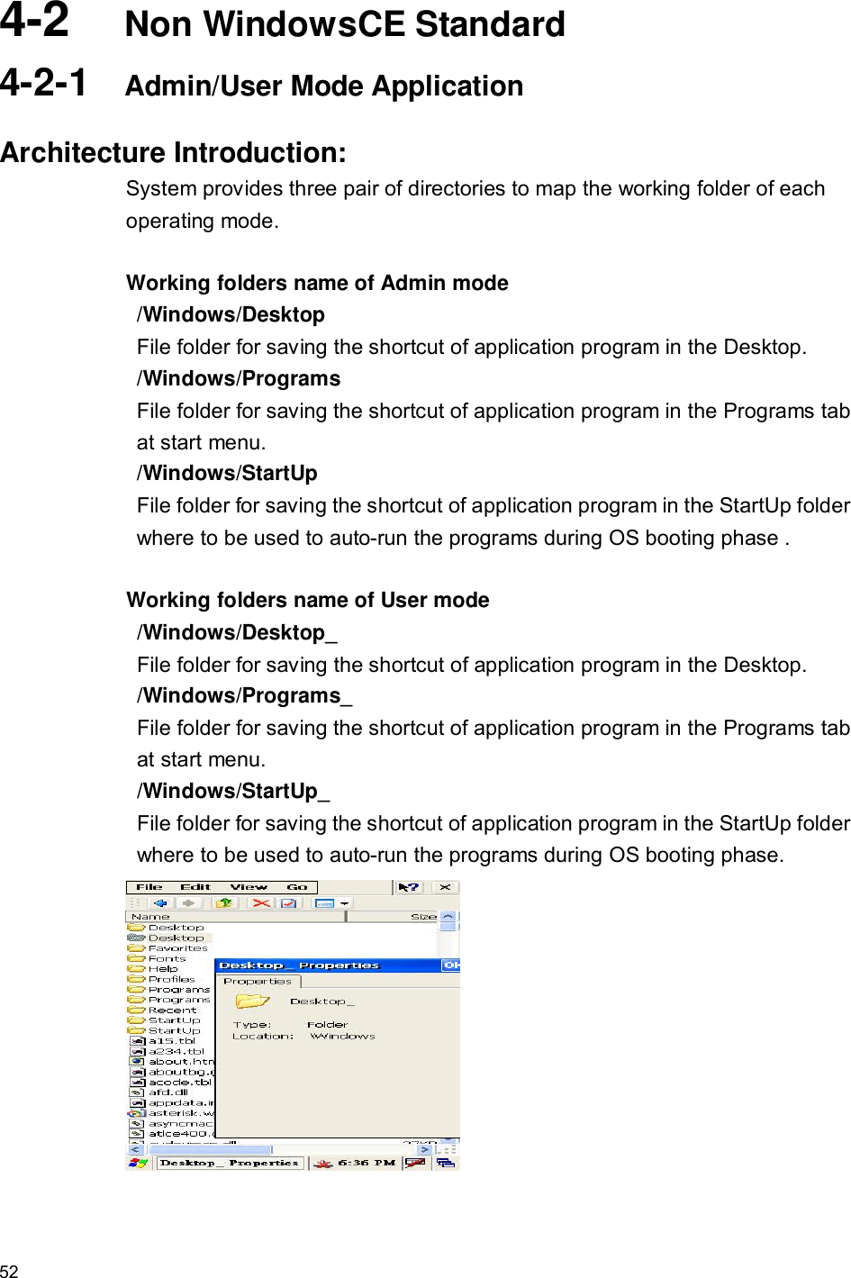
![10 Item Features Descriptions 13 Network Features l NDIS network driver architecture l TCP/IP l Windows Networking API /Redirector [SMB] l WinSock Support 14 Security l Authentication Services (SSPI) l Credential Manager l CrytoAPI 1.0 15 Applications and Service Development l .NET compact framework 2.0 l Active Template Library (ATL) l C Libraries and Runtimes l COM and DCOM l Microsoft Foundation Classes (MFC) l Object Exahange Protocol l Standard SDK for Windows CE l MSXML 3.0 16 Fonts l Courier New (Subset 1_30) l Tahoma (Subset 1_07) l Wingding 17 Multilingual l English (English software Input Panel) l Traditional Chinese l (Bopomofo/ Chan Jei software Input Panel, Handwriting) l Simplified Chinese (Shuang Pin software Input Panel) 18 OEM l Factory Device Manager l User mode / Admin mode operation modes](https://usermanual.wiki/FLYTECH-TECHNOLOGY/P2340000/User-Guide-1162425-Page-20.png)


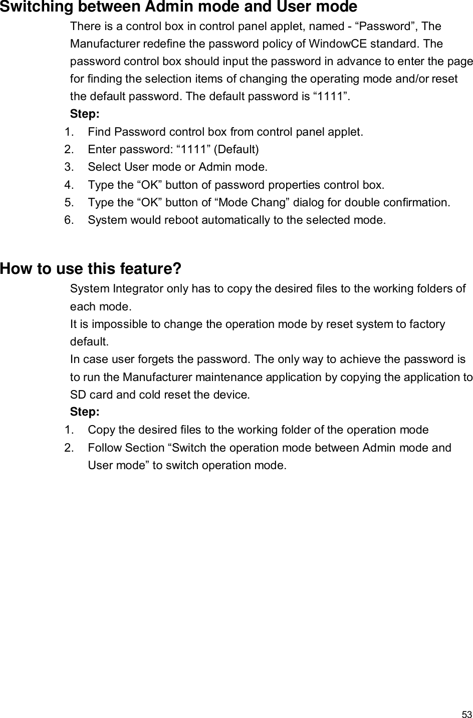
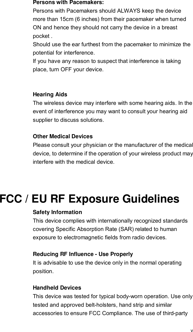
![55 Merge an application program into default operating system by using the OEM Device Manager u Example: - For Auto-running the OEM application at booting phase of user mode when after reset to factory default. 1. Create a file directory “GHARST” in root folder of SD card. 2. Change into “GHART” folder to create directory “Windows”. 3. Change into “Windows” folder to create directory “StartUp_”. 4. Copy the OEM application file into “Windows->StartUp_” folder. [Second way is: copy OEM application file into “Windows” folder, creates a lnk file of OEM application and copy it into “Windows->StartUp_” folder. 5. Put SD card into the SD socket on B21 device. 6. Use OEM Device Manager to merge all files in “GHARST” folder in SD card into device. After the file integration process, all OEM specify files will be the system default components of B21 device. - Place the OEM application at “Programs” folder in Windows Start menu - System running in user mode. 1. Create a file directory “GHARST” in root folder of SD card. 2. Change into “GHART” folder to create directory “Windows”. 3. Change into “Windows” folder to create directory “Programs_”. 4. Copy the OEM application file into “Windows->Programs_” folder. [Second way is: copy OEM application file into “Windows” folder, creates a lnk file of OEM application and copy it into “Windows->Programs_” folder] 5. Put SD card into the SD socket on B21 device. 6. Use OEM Device Manager to merge all files in “GHARST” folder in SD card into device. After the file integration process, all OEM specify files will be the system default components of B21 device. How to overwrite the factory default settings by using the OEM Device Manager Two config files are used to modify the registry settings of factory default mode. System Integrator is easy to add and/or modify the registry key without upgraded the image of WindowsCE operating system. The way to remove the registry key is to put empty to the key value in the config file. System.cfg – Using for early registry initialization stage at booting phase.](https://usermanual.wiki/FLYTECH-TECHNOLOGY/P2340000/User-Guide-1162425-Page-65.png)
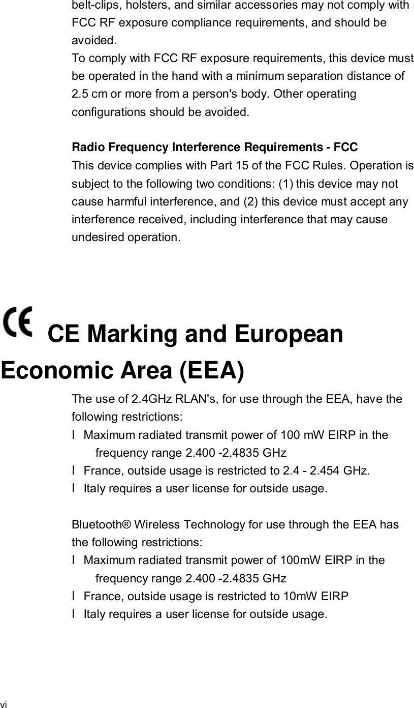
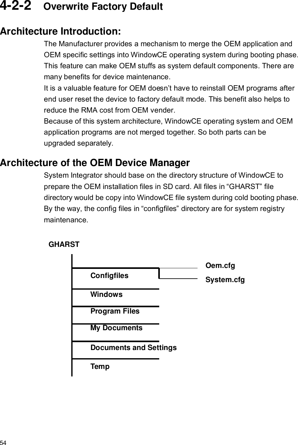
![56 Oem.cfg – Using for system registry initialization stage at booting phase. u Example: - Overwrite the factory default backlight level setting. 1. Create a file directory “GHARST” in root folder of SD card. 2. Change into “GHART” folder to create directory “configfiles”. 3. Prepare the oem.cfg config file by text editor. Input following setting: [HKEY_CURRENT_USER\ControlPanel\BackLight] "BatteryBacklightLevel"=dword:7 "ACBacklightLevel"=dword:A 4. Copy oem.cfg file into “configfiles” folder. 5. Put SD card into the SD socket on B21 device. 6. Use OEM Device Manager to merge all files in “GHARST” folder in SD card into device. After the integration process, all OEM desired settings will be the system default settings of B21 device. - Overwrite the default WiFi state to power on mode. (Default is power down) 1. Create a file directory “GHARST” in root folder of SD card. 2. Change into “GHART” folder to create directory “configfiles”. 3. Prepare the system.cfg config file by text editor. Input following setting: [HKEY_LOCAL_MACHINE\Comm\NdisPower] "GSPI86861"=dword:0 ;0(D0), 1(D1), 2(D2), 3(D3), 4(D4)-Default 4. Copy system.cfg file into “configfiles” folder. 5. Put SD card into the SD socket on B21 device. 6. Use OEM Device Manager to merge all files in “GHARST” folder in SD card into device. After the integration process, all OEM desired settings will be the system default settings of B21 device. - Remove a registry key from the registry in factory default settings Only have to put the key equal to empty. factory manager will remove the specify key from default system registry setting. Example: [HKEY_LOCAL_MACHINE\RegistryKey] "ValueName"=](https://usermanual.wiki/FLYTECH-TECHNOLOGY/P2340000/User-Guide-1162425-Page-66.png)
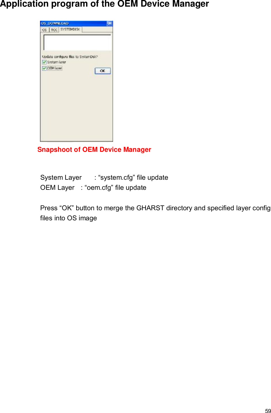
![57 Overwrite Factory Default Registry Settings for OEM Customization (oem.cfg) <1> Bluetooth operating mode [HKEY_LOCAL_MACHINE\System\State\Hardware\Bluetooth] “BluetoothOn”=dword:1 ; 1-> BT on, 0->BT off “BluetoothWakeUpEnable”=dword:0 ;1-> Enable, 0-> Disable <2> WiFi operating mode [HKEY_LOCAL_MACHINE\Comm\NdisPower] “GSPI86861”=dword:4 ; 0-> WiFi on, 4->WiFi off [HKEY_LOCAL_MACHINE\Comm\GSPI86861\Parms] “PowerMode” = dword:1 ; 0: Performance mode, 1: PS mode “MultipleDTim”=dowrd:2 ; PS mode (0,1,2,3,4 –most power saving) <3> Screen rotation feature [HKEY_LOCAL_MACHINE\System\GDI\Rotation] “Angle”=dword:1 ;(Decimal 0->0 degree, 90->90 degree, 180->180 degree, 270->270 degree) // Manual rotate mode “AutoRotate”=dword:F // Auto Rotate control ; bit 15 = 0 (Manual rotate) = 1 (Auto Rotate) ; bit 0 = 0 (180 degree ignored) = 1 (180 degree accepted) ; bit 1 = 0 (90 degree ignored) = 1 (90 degree accepted) ; bit 2 = 0 (0 degree ignored) = 1 (0 degree accepted) ; bit 3 = 0 (270 degree ignored) = 1 (270 degree accepted) <4> Backlight control [HKEY_CURRENT_USER\ControlPanel\BackLight] "BatteryBacklightLevel"=dword:7 // Backlight level of battery only "ACBacklightLevel"=dword:A // Backlight level of AC IN mode "BatteryTimeout"=dword:3c // Backlight timeout value of battery only mode "ACTimeout"=dword:258 // Backlight timeout value of AC IN mode "DimTimeOut"=dword:1E // Backlight DIM mode timeout "UseBattery"=dword:0 // Battery only mode timeout Enable/Disable "UseExt"=dword:0 // AC IN mode timeout Enable/Disable "UseDim"=dword:0 // Backlight DIM mode](https://usermanual.wiki/FLYTECH-TECHNOLOGY/P2340000/User-Guide-1162425-Page-67.png)
![58 Enable/Disable <5> Keypad control [HKEY_LOCAL_MACHINE\Drivers\BuiltIn\KEYPAD] "KeyPadSet0"=dword:27280000 "KeyPadSet1"=dword:25260000 <6> CPU operating frequency control Option1: Dynamic Mode [HKEY_LOCAL_MACHINE\Drivers\BuiltIn\IPM] "ProfileType"=dword:0 Option2: Performance Mode [HKEY_LOCAL_MACHINE\Drivers\BuiltIn\IPM] "ProfileType"=dword:1 "Speed"=dword:0 Option3: Power Saving Mode [HKEY_LOCAL_MACHINE\Drivers\BuiltIn\IPM] "ProfileType"=dword:1 "Speed"=dword:4](https://usermanual.wiki/FLYTECH-TECHNOLOGY/P2340000/User-Guide-1162425-Page-68.png)
![60 Overwrite display backlight settings Once the backlight is enabled, you can set separately both battery backlight setting and backlight setting of AC power. System Integrator can use Control Panel to change the setting values or modify the following registry keys to change settings. Note that the units for the timeout values are in seconds Registry Key: [HKEY_CURRENT_USER\ControlPanel\Backlight] Modify display backlight settings for AC power Values: - UseExt : 1 (Enable/default) / 0 (Disable) - ACTimeout : 15/30/60/120/300/600(default)/900/1800 - ACBacklightLevel : 0/1/2/3/4/5/6/7/8/9/10(default) Modify display backlight settings for battery power Values: - UseBattery : 1 (Enable/default) / 0 (Disable) - BatteryTimeout : 15/30/60(default)/120/300 - BatteryBacklightLevel : 0/1/2/3/4/5/6/7(default)/8/9/10 Modify display backlight settings for DIM mode Values: - UseDim : 1 (Enable/default) / 0 (Disable) - DimTimeout : 15/30(default)/60/120/300 Example Code (Update backlight level) void UpdateRegistry(DWORD dwVal) { TCHAR szRegClass[] = TEXT("DWORD"); HKEY hRegBacklight; DWORD dwDisposition; if(ERROR_SUCCESS == RegCreateKeyEx(HKEY_CURRENT_USER, L"ControlPanel\\Backlight", 0, szRegClass, REG_OPTION_NON_VOLATILE, 0, NULL, &hRegBacklight, &dwDisposition)) { LONG lResult; DWORD dwType = REG_DWORD; DWORD dwLen = sizeof(DWORD);](https://usermanual.wiki/FLYTECH-TECHNOLOGY/P2340000/User-Guide-1162425-Page-70.png)

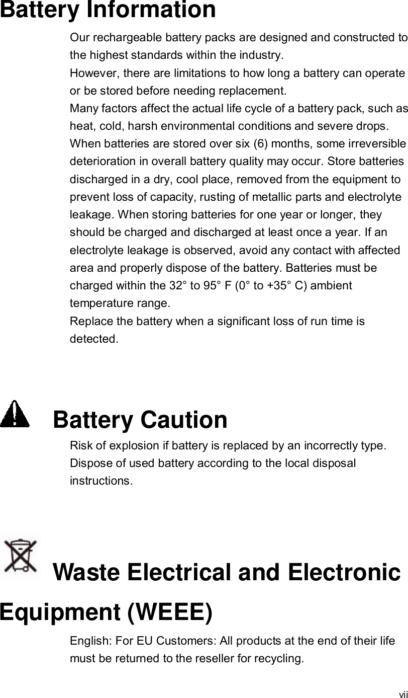
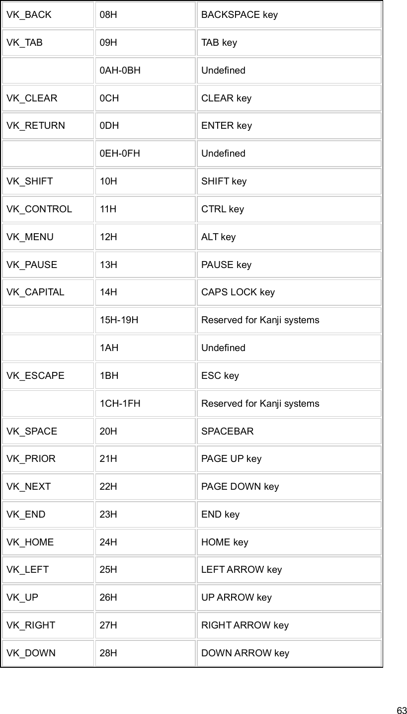
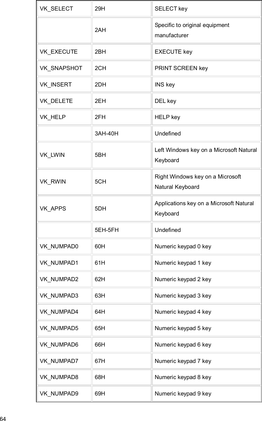
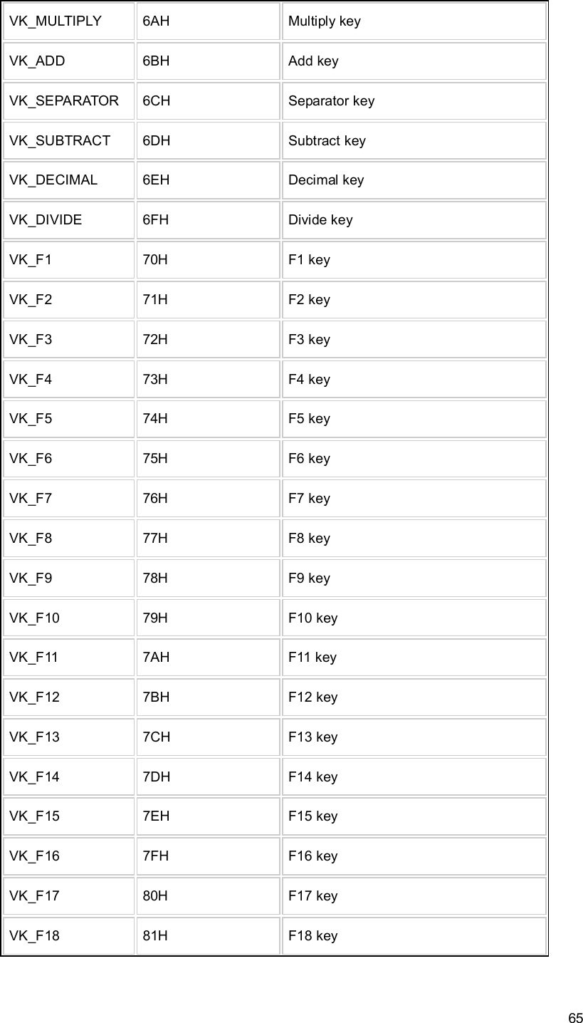
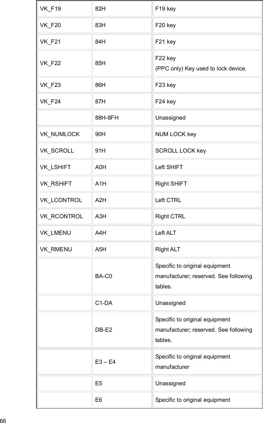
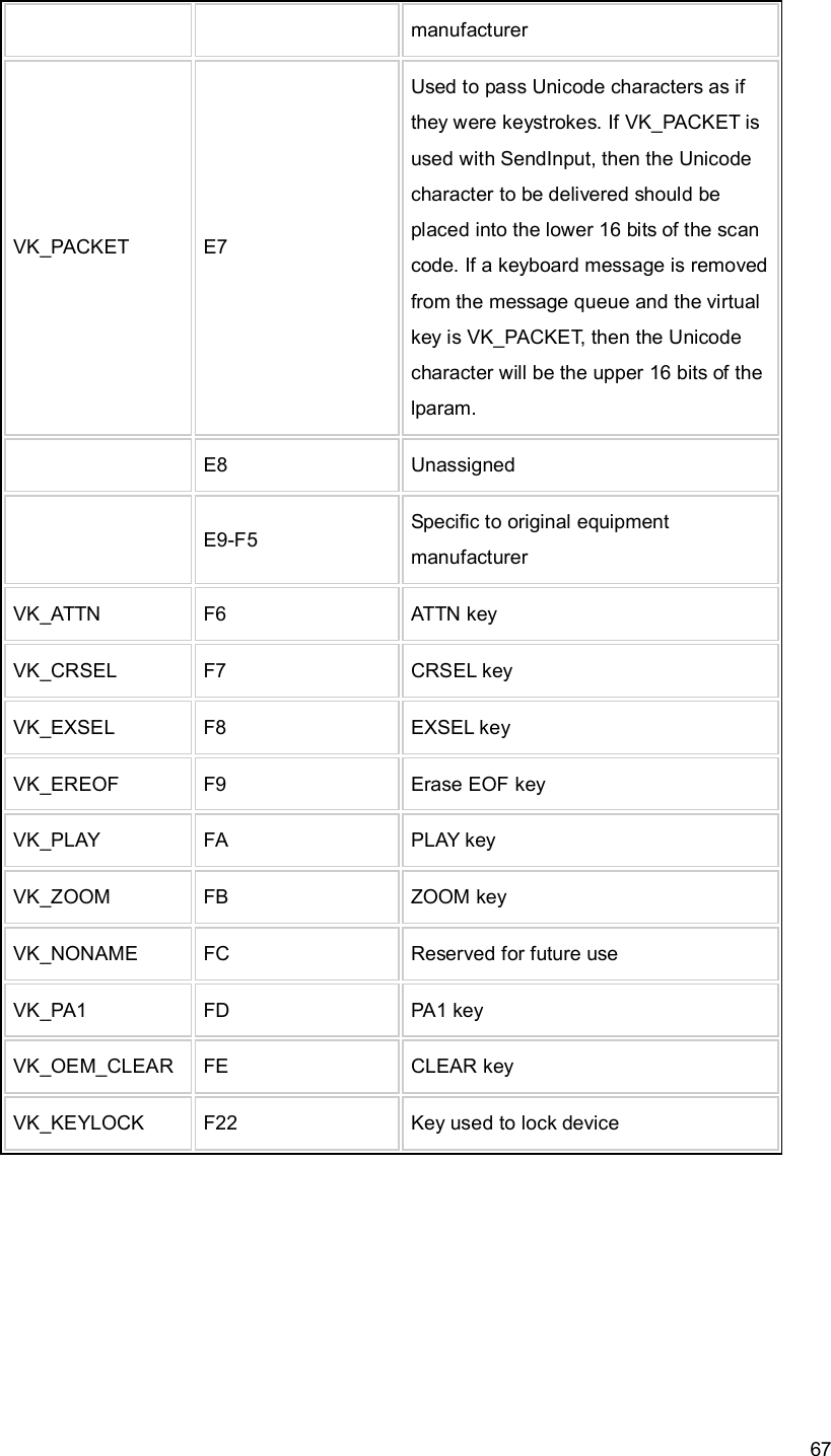
![62 4-2-3 Programmable button feature Five buttons designed on front bottom of B21 device. Keypad driver will report the Windows virtual key code what described in a registry key to system when button to be pressed. System Integrator can modify the registry key value of each button separately. The modification will work on next button pressed instantly. - One key with combination function: combined Power button and “Enter” button functions into one button. This button is a fix function button, no available API for function modification. - 4 programmable buttons: defined to be 4 way navigation keys by system default mode. All buttons can be re-programmed to one of the number of Windows keyboard virtual key code to redefine the button function by registry modification. Registry key definition Registry Key: [HKEY_LOCAL_MACHINE\Drivers\BuildIn\KEYPAD] Value Name DWORD (HEX) KeyPadSet0 27 (Right) 28(Down) 00 00 KeyPadSet1 25 (Left) 26 (Up) 00 00 Windows virtual key code Virtual key codes Symbolic constant Hexadecimal value Mouse or keyboard equivalent VK_LBUTTON 01H Left mouse button VK_RBUTTON 02H Right mouse button VK_CANCEL 03H Control-break processing VK_MBUTTON 04H Middle mouse button on a three-button mouse 05H-07H Undefined](https://usermanual.wiki/FLYTECH-TECHNOLOGY/P2340000/User-Guide-1162425-Page-72.png)
![68 Example code void ModifyKeyCode(DWORD data) { //modify the virtual key code of up button HKEY hKeyPad = NULL; TCHAR RegStr[14], if (ERROR_SUCCESS == RegOpenKeyEx(HKEY_LOCAL_MACHINE, L"Drivers\\BuiltIn\\KEYPAD", 0, 0, &hKeyPad)) { wsprintf(RegStr,L"KeyPadSet0"); //assign value name of up button dwSize = sizeof(DWORD); if (ERROR_SUCCESS == RegQueryValueEx(hKeyPad, RegStr, NULL, &dwType, (LPBYTE)& SaveReg, &dwSize)) { data = (data << 24) & 0xff000000; SaveReg = (SaveReg &0x00ffffff) | data; // modify the virtual key code of up button RegSetValueEx(hKeyPad, RegStr, NULL, dwType, (LPBYTE)&SaveReg, dwSize); } } RegCloseKey(hKeyPad); }](https://usermanual.wiki/FLYTECH-TECHNOLOGY/P2340000/User-Guide-1162425-Page-78.png)