FLYTECH TECHNOLOGY P2350000 Handheld Terminal User Manual
FLYTECH TECHNOLOGY CO., LTD Handheld Terminal
user manual
Revision v1.1 Oct. 2010
FLYTECH
Handheld Terminal
P235
User Manual
ii
Copyright
Copyright 2010 October
All Rights Reserved
Manual Version 1.1
P/N:
The information contained in this document is subject to change
without notice.
We make no warranty of any kind with regard to this material,
including, but not limited to, the implied warranties of
merchantability and fitness for a particular purpose. We shall not
be liable for errors contained herein or for incidental or
consequential damages in connection with the furnishing,
performance, or use of this material.
This document contains proprietary information that is protected
by copyright. All rights are reserved. No part of this document
may be photocopied, reproduced or translated to another
language without the prior written consent of the manufacturer.
TRADEMARK
The material in this manual is subject to change without notice.
Bluetooth is a registered trademark of Bluetooth SIG.
Microsoft®, Windows® and ActiveSync® are either registered
trademarks or trademarks of Microsoft Corporation.
All other product or service names are the property of their
respective owners.

iii
Revision History
Changes to the original user manual are listed below:
Version Date Description
1.0 2010/03 z Initial release
1.1 2010/10 z MSR module added
z Safety message updated
iv
Safety
Regulatory Information:
Caution: Only use approved and UL Listed accessories, battery
packs and battery chargers. Do NOT attempt to charge
damp/wet mobile computers or batteries. All components must
be dry before connecting to an external power source.
Power Supply
Use only the approved power supply 50-14000-148 output rated
5 Vdc and minimum 2 A. The power supply is certified to
EN60950-1 with SELV outputs. Use of alternative power supply
will invalidate any approval given to this device and may be
dangerous.
Warning for Use of Wireless Devices
Please observe all warning notices with regard to the usage of
wireless devices.
Potentially Hazardous Atmospheres
You are reminded of the need to observe restrictions on the use
of radio devices in fuel depots, chemical plants etc. and areas
where the air contains chemicals or particles (such as grain, dust,
or metal powders)
and any other area where you would normally be advised to turn
off your vehicle engine.
Safety in Aircraft
Switch off your wireless device whenever you are instructed to
do so by airport or airline staff.
Pacemakers
Pacemaker manufacturers recommended that a minimum of
15cm (6 inches) be maintained between a handheld wireless
device and a pacemaker to avoid potential interference with the
pacemaker. These recommendations are consistent with
independent research and recommendations by Wireless
Technology Research.
v
Persons with Pacemakers:
Persons with Pacemakers should ALWAYS keep the device
more than 15cm (6 inches) from their pacemaker when turned
ON and hence they should not carry the device in a breast
pocket .
Should use the ear furthest from the pacemaker to minimize the
potential for interference.
If you have any reason to suspect that interference is taking
place, turn OFF your device.
Hearing Aids
The wireless device may interfere with some hearing aids. In the
event of interference you may want to consult your hearing aid
supplier to discuss solutions.
Other Medical Devices
Please consult your physician or the manufacturer of the medical
device, to determine if the operation of your wireless product may
interfere with the medical device.
FCC / EU RF Exposure Guidelines
Safety Information
This device complies with internationally recognized standards
covering Specific Absorption Rate (SAR) related to human
exposure to electromagnetic fields from radio devices.
The maximum level of Specific Absorption Rate (SAR) measured
is 0.501W/kg.
Reducing RF Influence - Use Properly
It is advisable to use the device only in the normal operating
position.

vi
Handheld Devices
This device was tested for typical body-worn operation. Use only
tested and approved belt-holsters, hand strap and similar
accessories to ensure FCC Compliance. The use of third-party
belt-clips, holsters, and similar accessories may not comply with
FCC RF exposure compliance requirements, and should be
avoided.
To comply with FCC RF exposure requirements, this device must
be operated in the hand. Other operating configurations should
be avoided.
Radio Frequency Interference Requirements - FCC
This device complies with Part 15 of the FCC Rules. Operation is
subject to the following two conditions: (1) this device may not
cause harmful interference, and (2) this device must accept any
interference received, including interference that may cause
undesired operation.
Radio Frequency Interference Requirements – IC
This device complies with RSS-210 of the IC Rules. Operation is
subject to the following two conditions: (1) this device may not
cause harmful interference, and (2) this device must accept any
interference received, including interference that may cause
undesired operation.
CE Marking and European
Economic Area (EEA)
The use of 2.4GHz RLAN's, for use through the EEA, have the
following restrictions:
z Maximum radiated transmit power of 100 mW EIRP in the
frequency range 2.400 -2.4835 GHz
z France, outside usage is restricted to 2.4 - 2.454 GHz.
z Italy requires a user license for outside usage.

vii
Bluetooth® Wireless Technology for use through the EEA has
the following restrictions:
z Maximum radiated transmit power of 100mW EIRP in the
frequency range 2.400 -2.4835 GHz
z France, outside usage is restricted to 10mW EIRP
z Italy requires a user license for outside usage.
Battery Information
Our rechargeable battery packs are designed and constructed to
the highest standards within the industry.
However, there are limitations to how long a battery can operate
or be stored before needing replacement.
Many factors affect the actual life cycle of a battery pack, such as
heat, cold, harsh environmental conditions and severe drops.
When batteries are stored over six (6) months, some irreversible
deterioration in overall battery quality may occur. Store batteries
discharged in a dry, cool place, removed from the equipment to
prevent loss of capacity, rusting of metallic parts and electrolyte
leakage. When storing batteries for one year or longer, they
should be charged and discharged at least once a year. If an
electrolyte leakage is observed, avoid any contact with affected
area and properly dispose of the battery. Batteries must be
charged within the 32° to 95° F (0° to +35° C) ambient
temperature range.
Replace the battery when a significant loss of run time is
detected.
Battery Caution
Risk of explosion if battery is replaced by an incorrectly type.
Dispose of used battery according to the local disposal
instructions.

viii
Safety Caution
Note: To comply with IEC60950-1 Clause 2.5 (limited power
sources, L.P.S) related legislation, peripherals shall be 4.7.3.2
"Materials for fire enclosure" compliant.
4.7.3.2 Materials for fire enclosures
For MOVABLE EQUIPMENT having a total mass not exceeding
18kg.the material of a
FIRE ENCLOSURE, in the thinnest significant wall thickness
used, shall be of V-1 CLASS MATERIAL or shall pass the test of
Clause A.2.
For MOVABLE EQUIPMENT having a total mass exceeding
18kg and for all STATIONARY EQUIPMENT, the material of a
FIRE ENCLOSURE, in the thinnest significant wall thickness
used, shall be of 5VB CLASS MATERIAL or shall pass the test of
Clause A.1
Waste Electrical and Electronic
Equipment (WEEE)
English: For EU Customers: All products at the end of their life
must be returned to the reseller for recycling.
ix
Notational Conventions
The following conventions are used in this document:
Italics are used to highlight specific items in the general text,
and to identify chapters and sections in this and related
documents.
bullets (•) indicate:
• action items
• lists of alternatives
• lists of required steps that are not necessarily sequential
• Sequential lists (e.g., those that describe step-by-step
procedures) appear as numbered lists.
NOTE This symbol indicates something of special interest or
importance to the reader. Failure to read the note will not result in
physical harm to the reader, equipment or data.
CAUTION This symbol indicates that if this information is ignored,
the possibility of data or material damage may occur.
WARNING! This symbol indicates that if this information is
ignored the possibility that serious personal injury may occur.
x
Table of Contents
1 Introduction ......................................... 12
1-1 System Overview ................................................................... 12
1-2 Standard Components............................................................ 13
1-3 Optional Accessory ................................................................ 14
1-4 Hardware Description............................................................. 15
1-5 System Feature Description................................................... 18
2 Getting Started .................................... 21
2-1 Installing / Uninstalling a Micro SD Card ................................ 21
2-2 Install a Wrist Strap ................................................................ 22
2-3 Install a Hand Strap................................................................ 22
2-4 Charging the System.............................................................. 23
2-5 Backup Battery....................................................................... 24
2-6 Power on/off the Unit.............................................................. 25
2-7 Install a 4-Slot System Charging Cradle (Optional)................ 26
3 Using the System ................................ 27
3-1 Wi-Fi Connection Settings...................................................... 27
3-1-1 Connecting to an Existing Network................................... 27
3-1-2 Adding a New Network ..................................................... 29
3-1-3 Enhancing the WiFi Connection ....................................... 30
3-1-4 SSID Lock Function.......................................................... 31
3-2 Synchronization via USB Cable ............................................. 32
3-2-1 Mini USB Cable ................................................................ 32
3-2-2 Installing WindowsCE® ActiveSync® application............. 33
3-2-3 Installing the USB Cable................................................... 34
3-2-4 Start the Synchronization.................................................. 35
3-3 Backup and Restoring the System......................................... 37
3-3-1 Backup the System........................................................... 37
3-3-2 Restoring the System ....................................................... 38
3-4 Switching the Admin / User mode .......................................... 39
3-5 Power Management Settings ................................................. 40
xi
3-5-1 CPU Power Mode Settings............................................... 40
3-5-2 System Configuring Power Mode Settings ....................... 41
3-5-3 Display Backlight Settings ................................................ 42
3-5-4 WiFi Power Mode Settings ............................................... 43
3-6 Display Rotation ..................................................................... 44
3-7 LED Indicator Description....................................................... 45
3-8 Resetting the Mobile System.................................................. 46
3-8-1 Reset to the Factory Default Settings............................... 46
3-8-2 Cold Boot.......................................................................... 47
3-9 OS Image Update steps......................................................... 48
3-9-1 Unzip the RAR compressed file to Micro SD root directory48
3-9-2 Image update procedures................................................. 49
4 Application Programming Interface .. 51
4-1 Windows Embedded CE 5.0 Standard ................................... 51
4-2 Non WindowsCE Standard..................................................... 55
4-2-1 Admin/User Mode Application........................................... 55
4-2-2 Overwrite Factory Default................................................. 57
4-2-3 Vibration notification feature ............................................. 65
12
1 Introduction
This chapter introduces the parts, accessories of the mobile system.
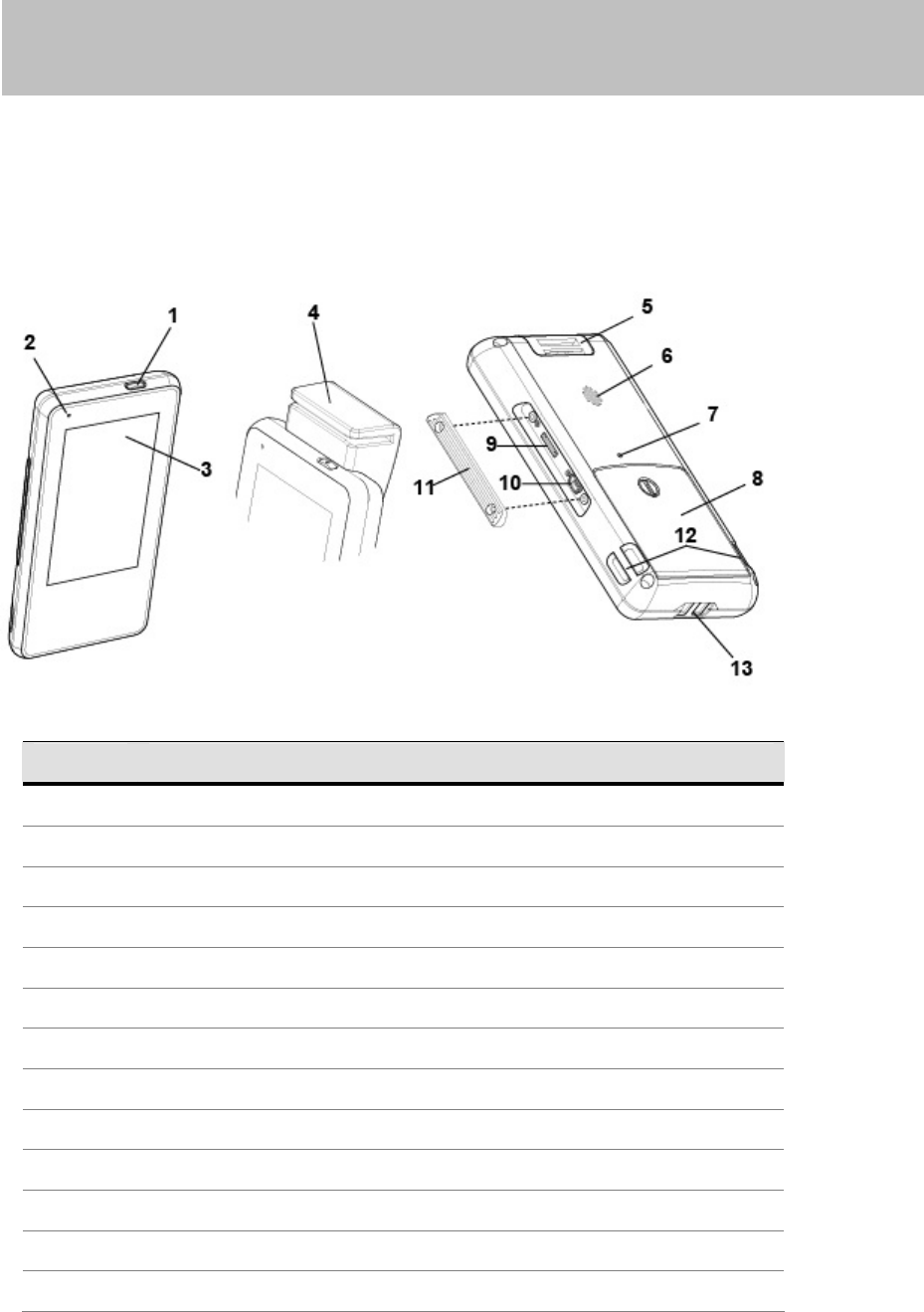
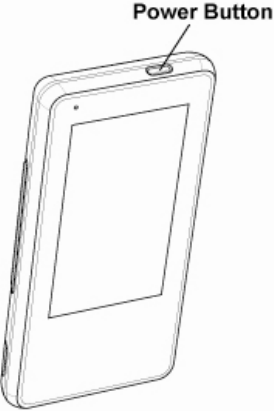
1-1 System Overview
System Overview table -1
Location
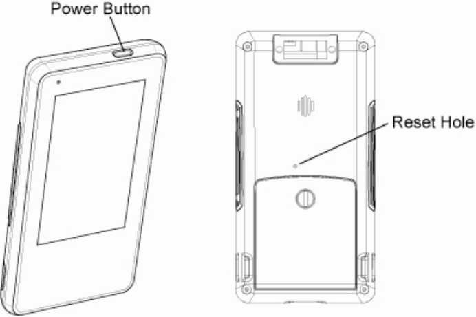
1 Power Button
2 LED Indicator
3 4.3” TFT with Touch Screen
4 MSR module
5 Hand Strap Installation Ring
6 Speaker
7 Reset Hole
8 Battery Door
9 Micro SD slot
10 Mini USB connector
11 I/O Cover
12 Hand Strap / Wrist Strap Installation Ring at both sides
13 Charging Slot
13
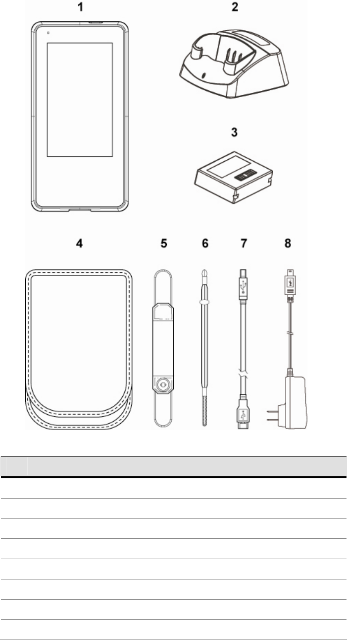
1-2 Standard Components
Items
1 Mobile system
2 Single slot system charger Cradle
3 Main battery
4 Holster
5 Hand strap
6 Wrist strap
7 USB cable (connecting with PC for synchronization)
8 USB-AC Adapter for connecting to single slot system charging cradle
14
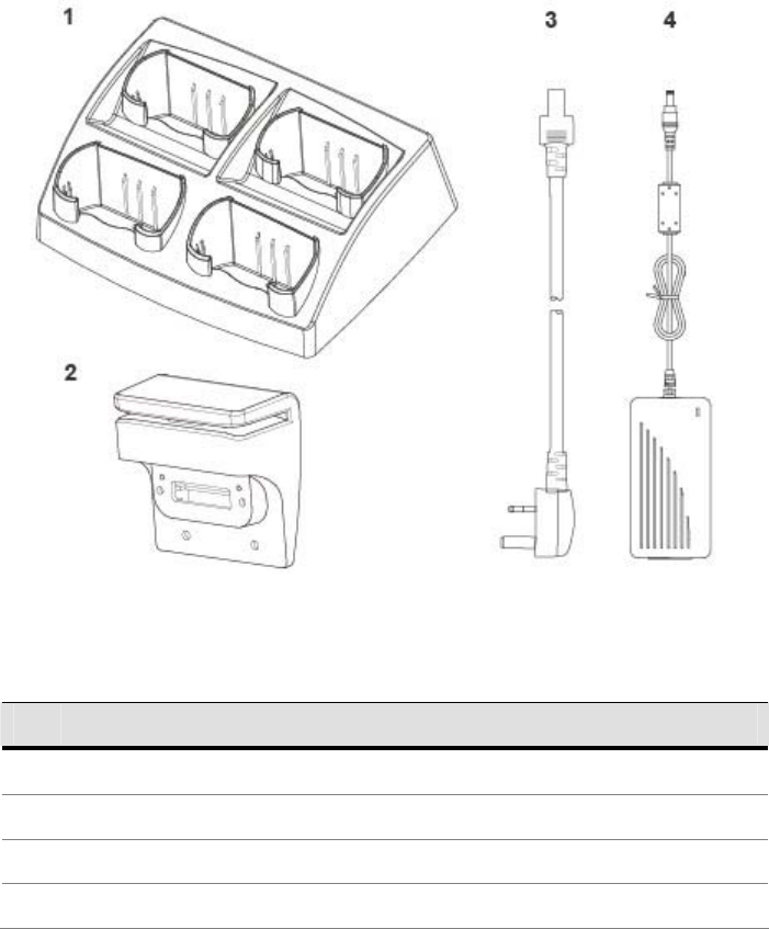
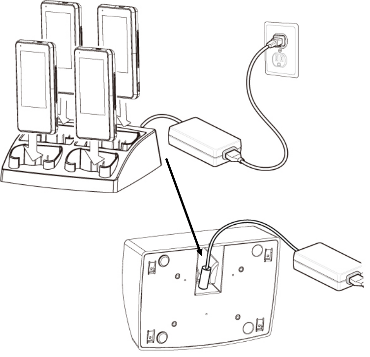
1-3 Optional Accessory
Items
1 4-slot system charger cradle
2 MSR module (will be installed prior to shipping)
3 Power cord for 4-slot system charging cradle
4 Power adapter for 4-slot system charging cradle

15
1-4 Hardware Description
Item Features Descriptions
1 Main Processor z Marvell PXA270 416MHz (Xscale Core)
2 System Memory
z 128Mbytes SDRAM
z Approximately 115MB used for system operation
remainder for storing system loader and data
3 System Storage
z 1Gbytes Flash (ROM file system)
z More than 300MB for storing WindowCE image
and OEM application programs
z Approximately 600MB left for system and user
storage.
z Approximately 100MB left for storing OEM data
and configuration. This device provides a
specific mechanism to let system integrator easily
to integrate the OEM applications and device
configurations into device as factory default mode
without merging OEM applications into
WindowCE image It can help system integrator
doesn’t have to maintain the device after end user
crashed the device by reset device to factory
default mode or on-line updated the OS image
from internet
4 Display z PXA270 Display controller
z Shared System Memory Video Frame Buffer
z Resolution :480 x 272 pixels, 16 bit color
z 4 way Orientation Detector
5 LCD z 4.3 inches TFT LCD – WQVGA (480 x 272 pixels
resolution)
z Transmissive display mode
z Digital RGB 8bit color depth, 8 LED backlight

16
Item Features Descriptions
6 Touch Panel z LCD panel with touch
z Resistor 80% Transparency (Film to Glass type)
7 Audio z Stereo audio system with mono speaker design
z 1W speaker amplifier
8 Secure Digital
Socket
z Micro SD memory card (Support up to: 2Gbytes)
9 WiFi IEEE
80211b/g
z Auto fallback mode : 6M~54M(80211g),
1M~11M(80211b)
z Complies with Wireless Ethernet Compatibility
Alliance
z Supports hardware signaling BT WiFi
coexistence
z Link LED indicator
z Maximum Output Power :
+15dBm(Avg)/+22dBm(Peak)
10 Bluetooth z Compliant with Bluetooth Specification V2.0
z Maximum Output Power : -3dBm (Class
2)(Avg)/-1dBm(Peak)
z Receive Sensitivity : Typical -78dBm
11 USB Client z USB Specification – 1.1 compliant
z Full-Speed operation on half-duplex at 12Mbps
baud rate
12 USB Host z Compliant with USB Specification 1.1 and OHCI
Spec
z Supports both low-speed and full-speed USB
devices
z Supports optional MSR

17
Item Features Descriptions
13 Power / Reset
buttons
z Power Button : Suspend/ Resume Device and
Power-on Key
z Reset Button : Warm Reset
z Press Power and Reset buttons simultaneously:
Cold Reset
14 LED indicators z Green: Battery charging finished
z Orange: Battery charging
z Blue: WiFi link active
z Red: Flashing – Battery low
On – Critical low battery
15 Vibrator z Vibration indicator
16 Battery z Liton battery pack 3.7V 2200 mA/h
z Charging time : maximum 4.0 ~ 4.5Hours
z Thermal / Over Charging Protections
17 Adapter z AC110V ~ 240V / DC5V ( 10W ) 50~60Hz

18
1-5 System Feature Description
Item Features Descriptions
1 Application z File Explorer
z Internet Explorer 6.0 for Windows CE
z Windows Media Player
z Windows CE standard shell
(Windows XP-like skin)
2 File System z ROM File system with hive registry
3 Graphic / Display z 480x272x16 (Landscape mode) as
panel default mode 272x480x16
(Portrait mode) as system default
mode
z Compliant with Graphics, Windowing
and Event Subsystems of Window
CE embedded.
z Still Image Codec Support
z DirectShow
z Supports screen rotation feature
4 User Input
Interface
z Stylus input rather than mouse input
capability
5 Audio z Audio playback feature only
z Support waveform audio
Input/Output device APIs
z Configurable sound enable/disable
feature of system event, message
notification, screen taps.
z MP3 Codec
z MPEG-1 Layer 1 and 2 audio codec
z Waveform audio renderer
z WMA Codec

19
Item Features Descriptions
6 Storage z Removable storage : Micro SD
memory (up to 2GB)
z Persistent storage: NAND flash
memory (On Board)
7 Data
Communication
WLAN
z Support seamless roaming in
IEEE802.11b/g WLAN authentication
infrastructure
z Support single SSID
z Support fast Wi-Fi roaming
z WPA and 802.11i security standard
(AES/CCMP and WEP with TKIP
security mechanism)
z Support Window Wireless Zero
Configuration service
8 Data
Communication
Bluetooth
z Compliant Bluetooth software
specification
z Window CE Bluetooth
communication software stack
z “SPP” “FTP” “Activesync” profile
supports
z Support Winsock Bluetooth
programming interface
9 Data
Synchronization
z Bluetooth Window CE Active-sync
z USB SD card reader
10 Vibration
Notification
z Support Programming API of
Window CE device manager
11 System Power
State
z Supports Remote Application
Interface (RAPI) for retrieving the
power status of the system
12 Backlight z Supports Programming API of
Windows CE device manager
z Supports 10 backlight levels

20
Item Features Descriptions
13 Network Features z NDIS network driver architecture
z TCP/IP
z Windows Networking API /Redirector
[SMB]
z WinSock Support
14 Security z Authentication Services (SSPI)
z Credential Manager
z CrytoAPI 1.0
15 Applications and
Service
Development
z .NET compact framework 2.0
z Active Template Library (ATL)
z C Libraries and Runtimes
z COM and DCOM
z Microsoft Foundation Classes (MFC)
z Object Exahange Protocol
z Standard SDK for Windows CE
z MSXML 3.0
16 Fonts z Courier New (Subset 1_30)
z Tahoma (Subset 1_07)
z Wingding
17 Multilingual z English (English software Input
Panel)
z Traditional Chinese
z (Bopomofo/ Chan Jei software Input
Panel, Handwriting)
z Simplified Chinese (Shuang Pin
software Input Panel)
18 OEM z OEM Device Manager
z User mode / Admin mode operation
modes
21
2 Getting Started
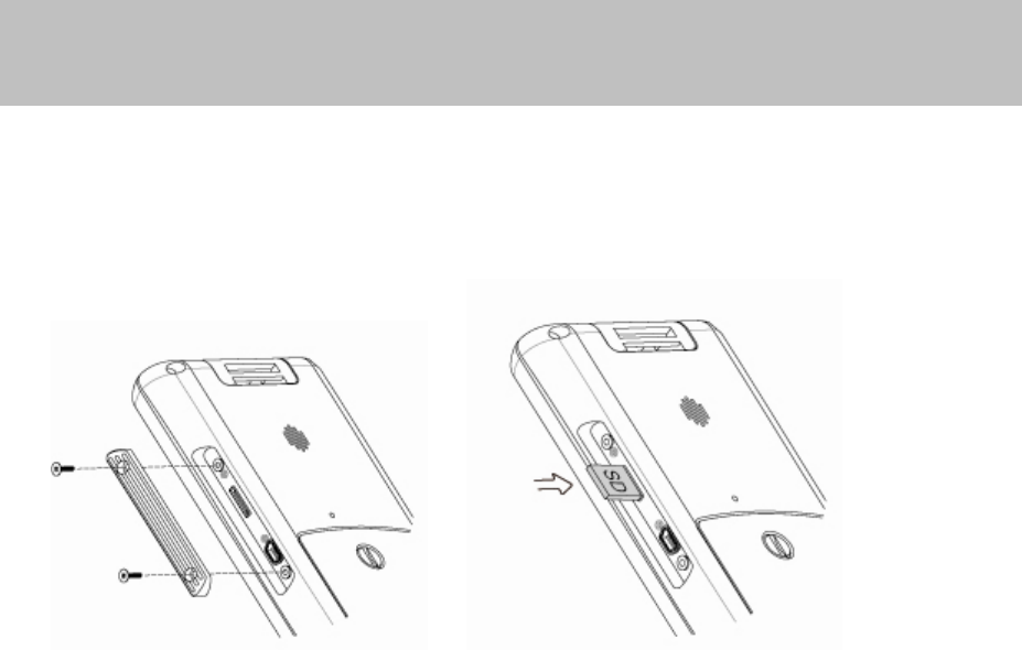
2-1 Installing / Uninstalling a Micro SD Card
1. Release the screws (x2) to open the I/O cover on the side of the
mobile system.
2. The Micro SD slot is a push-push type. Please push the Micro SD
card into the slot to install a micro SD card or push again and take it
out to remove it.
22
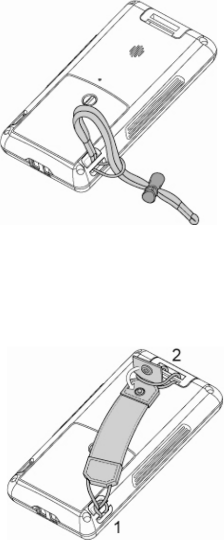
2-2 Install a Wrist Strap
1. Thread the wrist strap provided through the strap ring as pictured.
2-3 Install a Hand Strap
2. Thread the hand strap through the strap ring on either side of the
system.
3. Thread the hand strap through the plastic ring on the back of the
device and lock it to the hand strap
23
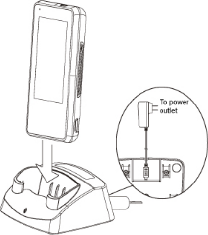
2-4 Charging the System
1. Connect the mini USB/AC Adapter to the bottom of the charging
cradle.
2. Connect the power cord of the AC-USB adapter to the power
outlet.
3. Slide the Mobile computer into the charging cradle. You should
see the charging LED appear.
24
2-5 Backup Battery
The internal Backup Battery has a 5 minute duration. The unit will
instantly resume functionality when battery is replaced within 5 minutes.
If battery is replaced outside of the 5 minute battery backup the system will
reset and power on automatically.
¾ Note: Normal procedure to power on the system is to hold
down the Power Button for 4 seconds
25
2-6 Power on/off the Unit
Power on the Unit
Press and hold the Power Button for 3 seconds to turn on the unit.
Power down the Unit
Press the Power Button for 4 seconds or select the "Start Menu">
"Suspend" to power down the unit.
26
2-7 Install a 4-Slot System Charging Cradle
(Optional)
1. Connect the power adapter and the power cord to the 4-slot
system charging cradle.
27
3 Using the System
3-1 Wi-Fi Connection Settings
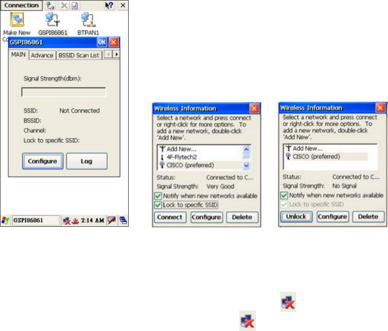
3-1-1 Connecting to an Existing Network
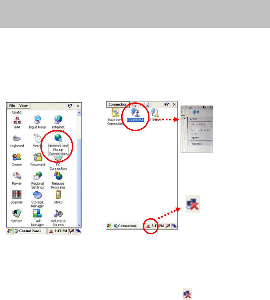
Enable Wireless Connection
1. Enable the Wireless Connection by selecting "Start" > "Settings" >
"Control Panel" > "Network and Dial-Up Connections".
2. Right click on the “GPS186861” and tap the “Enable” icon in the
drop down menu to access the wireless connection.
3. After Enabling the "GPSI86861", you will see the Icon appear
in the system tray.
28
Select a Network and get connection
4. You will see the “GPSI86861” window pop up after you double click
on the icon .
5. Press “Main” tab and “Configure” button.
6. Select the network you want and put the key (password) if needed,
then press “Connect” button to get connection.
¾ NOTE: You can create a new network by selecting “Add
New…” (please see Chapter 3-1-2 )
7. After the WiFi is successfully connected a message will show the
status of the connection and the icon ( ) in the system tray will
turn to ( ).
29
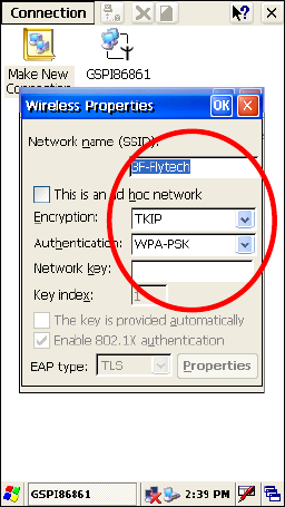
3-1-2 Adding a New Network
To add a new network connection, please enable the wireless connection
first by following the steps in Chapter 3-1-1.
1. The “Wireless Properties” dialog box pop up after pressing “Add
New…”.
2. Enter the Network name of the Network you would like to connect
to in the "Network name(SSID)" box. The select the Encryption and
Authentication methods, enter the password in the "Network key" .
3. You will have a successful connection when the Status shows
"Connected to xxx"
30
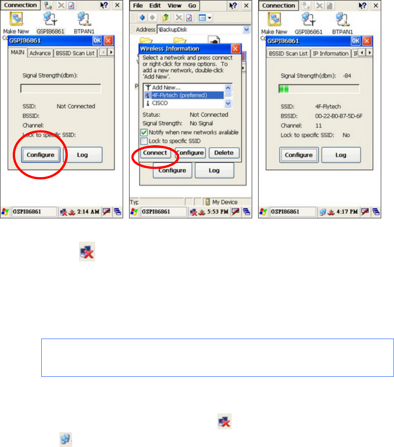
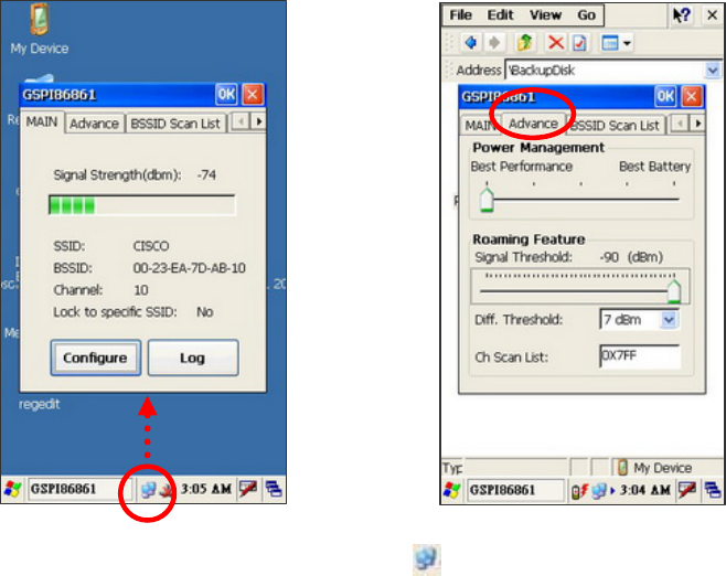
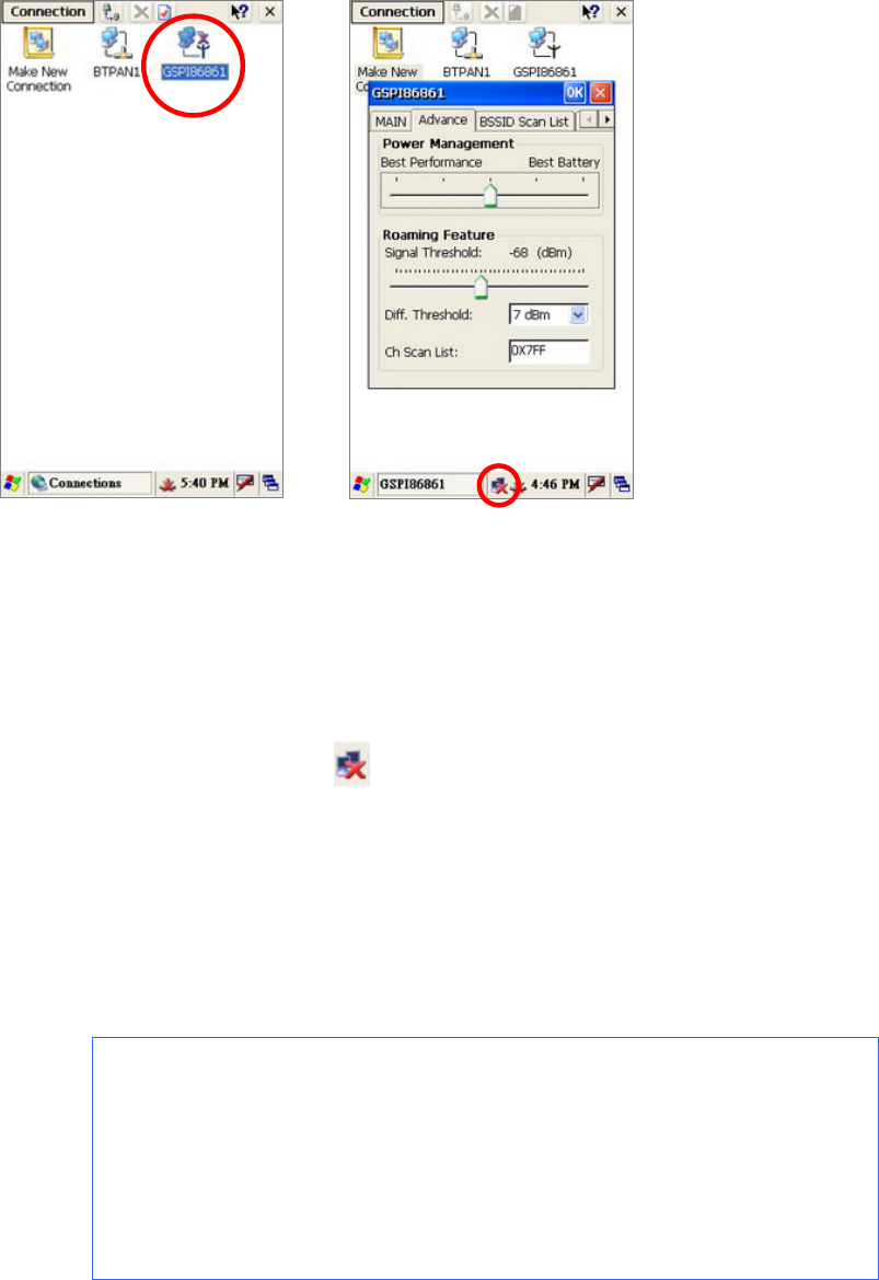
3-1-3 Enhancing the WiFi Connection
If the Signal Strength of the WiFi Connection remains low follow these
steps:
1. Please double-click on the icon in the system tray. The
“GSP186861” dialog will appear.
2. Please select “Advance” tab and move the “Power Management” to
the “Best Performance level” and the “Roaming Feature” to the far
right.
3. Press “OK” to save the settings.
31
3-1-4 SSID Lock Function
1. Enable Wireless Connection by following the steps in Chapter
3-1-1.
2. After enabling the Wireless Connection, the icon ( ) will appear
in the system tray. Double click the icon( ) and press the
"configure" button on the "GPSI86861" window.
3. Select a network you want and click the “Lock to specific SSID”
check box. Click “Connect” button to lock the SSID.
4. SSID is locked successfully when the "Status" shows "Connected
to xxx" on the Wireless information window.

32
3-2 Synchronization via USB Cable
3-2-1 Mini USB Cable
When Developing and debugging software use the WindowsCE®
ActiveSync® function via the USB Port.
A specific application program located in “Application” Folder and named
as “USB.EXE” to provide manual USB ActiveSync connection.
A specific USB cable would be required.
USB Cable Snapshot
(To Mobile System) (to PC)
Optional USB Cable is for Synchronization with the PC and Software
uploading and Debugging.
33
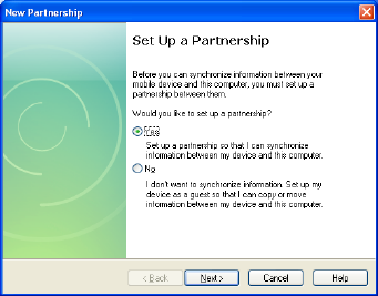
3-2-2 Installing WindowsCE® ActiveSync® application
To synchronize the Mobile System with PC, please install the “Microsoft
Active Sync” program on each PC first.
The set-up of a “Partnership” will be requested once after connecting the
USB Cable to the Mobile System and PC.
The Synchronization will run automatically after "Microsoft Active Sync"
and "Partnership Set-up" install successfully and the USB cable is
connected.
Refer to the Microsoft Official Website for details installation procedures
for the ActiveSync program.
34
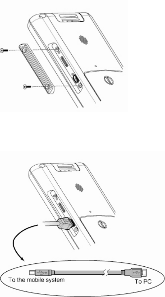
3-2-3 Installing the USB Cable
1. Unscrew the screws (x2) to open the I/O cover and access the mini
USB connector.
2. Connect the mobile system and the PC with the mini USB cable.
35
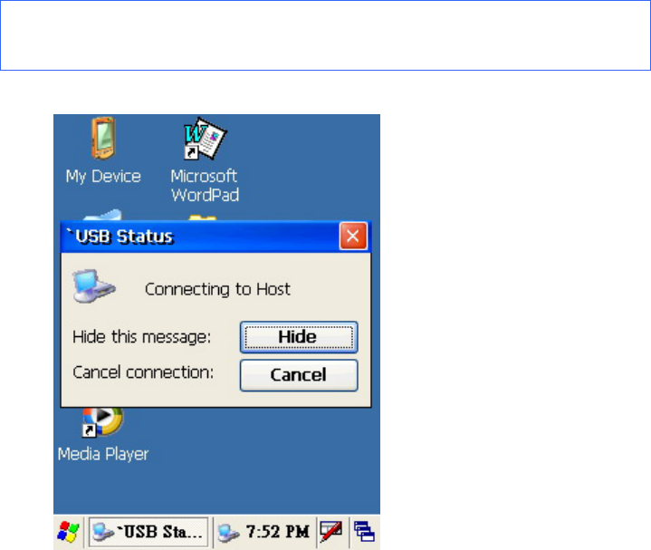
3-2-4 Start the Synchronization
The connection will automatically run and you can see the “USB Status”
dialog pop up after you connect the mobile system and a PC with the mini
USB cable provided.
¾ Note: please install the “Microsoft® ActiveSync®” program at
your PC before you start the synchronization.
36
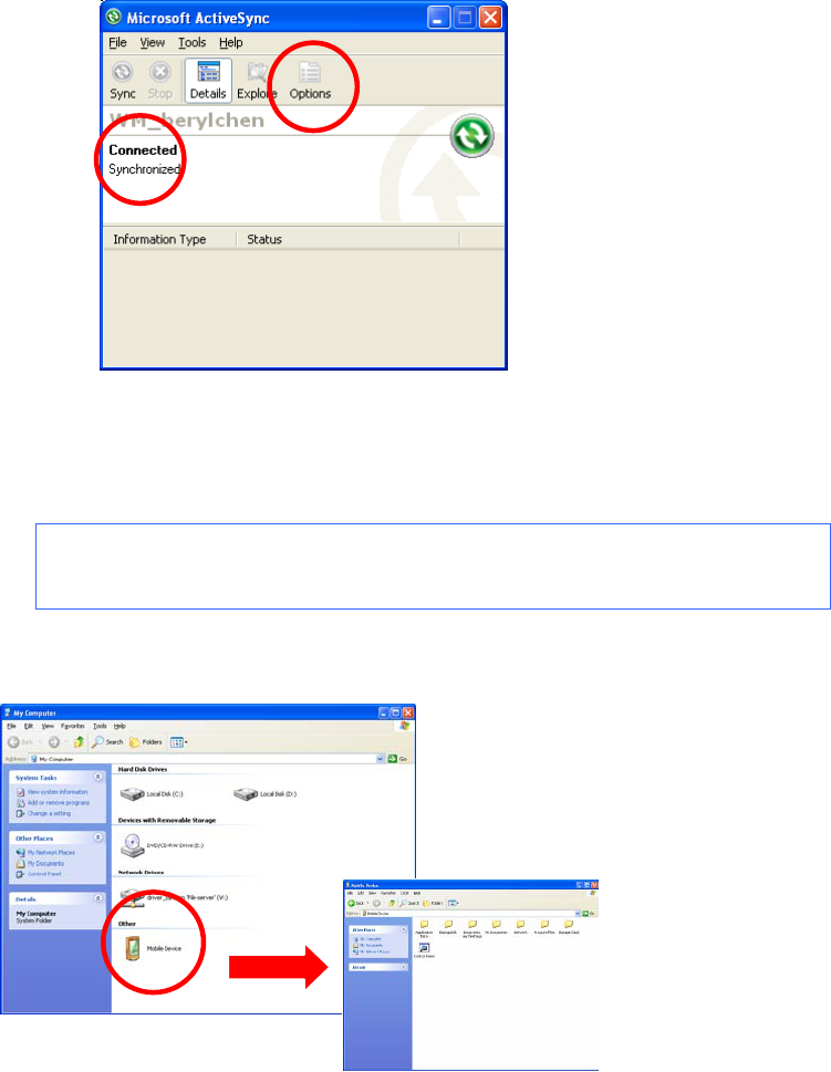
1. The “Microsoft ActiveSync” window will show “Connected” after
USB Cable is successfully connected.
¾ Note: Use the "Options" to set up the Synchronization on
your own.
2. Double click the “Mobile Device” icon by opening “My Computer” to
access the documents or files saved in the Mobile System.
37
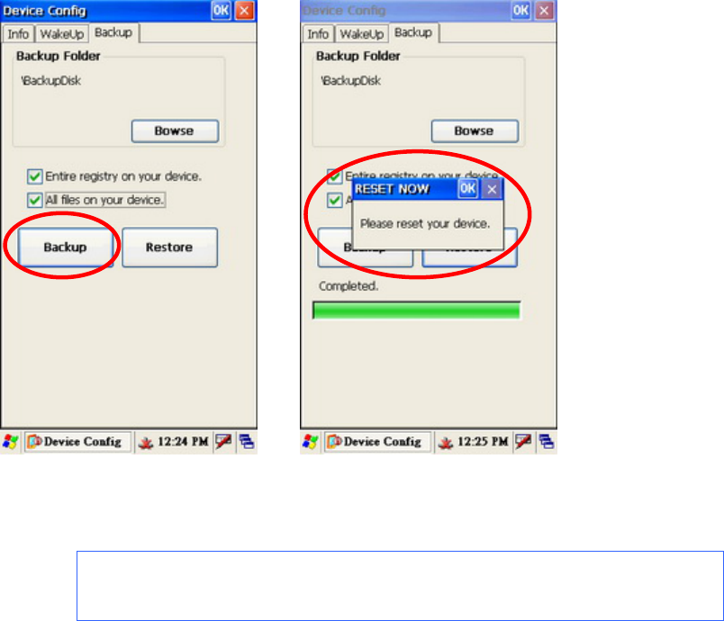
3-3 Backup and Restoring the System
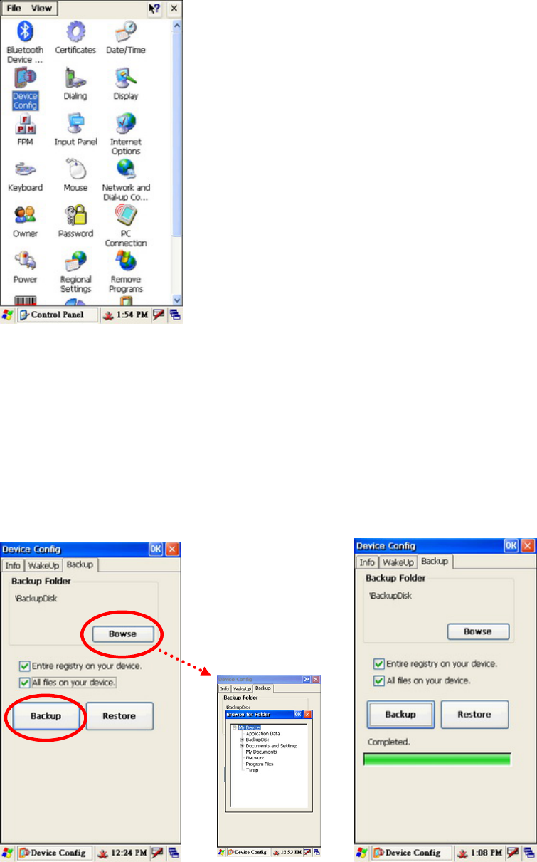
Go to “Start” > “Control Panel” > “Device Config”.
3-3-1 Backup the System
To restore the system, please follow the instructions in Chapter 3-4 and the
following steps.
1. Select “Backup” tab then enable the “Entire the registry on your
device” and the “All your files on your device” check boxes.
38
2. Press the "Browse" to select the location to save the Backup Files.
3. Press the "Backup" button to start the backup process.
3-3-2 Restoring the System
To restore the system, please follow the Chapter 3-4 and following
instructions.
1. Press “Restore”.
2. Press "OK" to finish the Restore.
¾ Note: System Restore means to restore the system to the
latest “Backup” version.
39
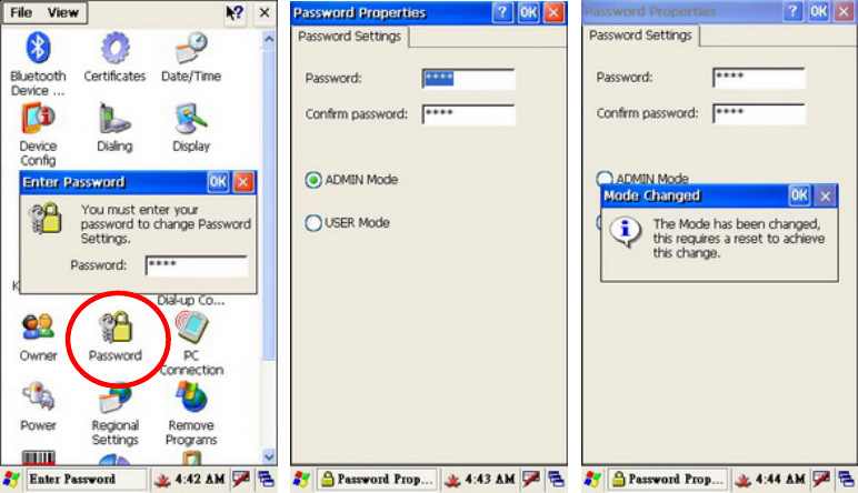
3-4 Switching the Admin / User mode
1. To access the Mode Change screen "Start Menu" > "Settings" >
"Control Panel" > "Password" > Enter Password (default is 1111).
2. The “Password Properties” dialog will popup after entering the
password (default), select the Mode you want. Press “OK” to save
the setting.
3. Once saved the "Mode Changed" dialog will popup. Press "OK"
to restart the system.
40
3-5 Power Management Settings
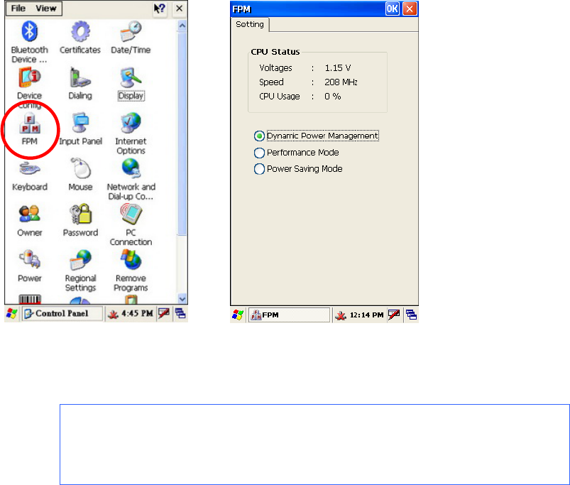
3-5-1 CPU Power Mode Settings
1. Select “Start” > ” Control Panel” > ” FPM” button
2. Select the mode you want on the “FPM” window.
¾ Note: The CPU Power Consumption is ranked as:
” Performance Mode” > ” Dynamic Power Management” > ”
Power Saving Mode”.
41
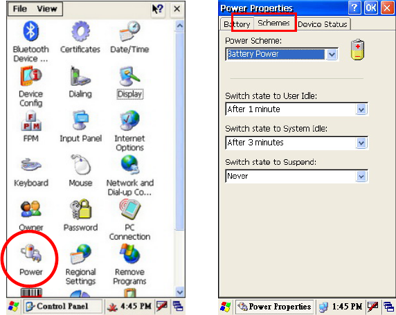
3-5-2 System Configuring Power Mode Settings
1. Click “Start” > ” Control Panel” > ” Power” button
2. Select “Schemes” tab.
3. Set up the power mode as “Battery Power” or “AC Power” in the
“Power Scheme” drop down menu.
4. Set the times for turning the Mobile System off or going in to
standby mode.
a. Switch state to User Idle.
b. Switch state to System Idle.
c. Switch state to suspend.
5. Press “OK” to save the settings.
42
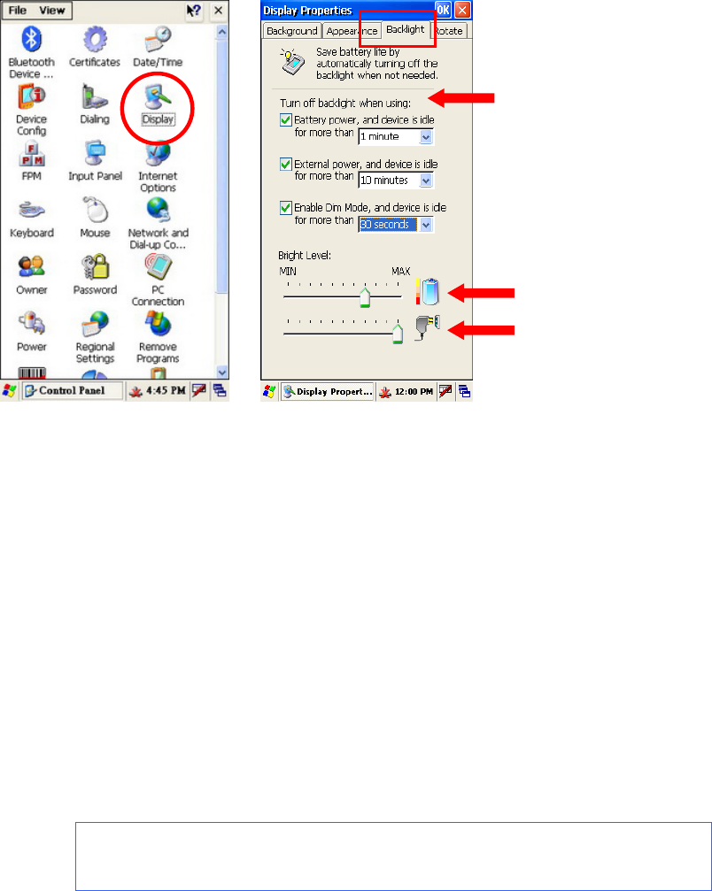
3-5-3 Display Backlight Settings
1. Go to “Start” > “Control Panel”.
2. Double click on the “Display” icon.
3. In the “Display Properties” window, select “Backlight” tab.
4. You can enable the backlight savings by checking and setting
turn-off time in the checkboxes of “Battery power…”, “External
power…” and “Enable Dim Mode…”
5. Drag the "Bright Level" slider to set the level for both Battery power
and External power.
6. Press "OK" to save the settings.
¾ Note: If you enable the "Dim Mode" it runs in dim mode until
using the plans set above.
43
3-5-4 WiFi Power Mode Settings
1. To access the network connections select "Start" > "Control Panel"
> "Netowrk and Dial-up Connections".
2. Hold and press "GSPI86861" button until the drop down menu
appears.
3. Press “Enable” in the drop down menu to active the WiFi
Connection or press icon in the system tray directly to active
the “GSPI86861” setup window as above right figure.
4. Tap the "Advanced" tab of the "GSPI86861".
5. Set the "Power Management" by dragging the slider on the "Best
Performance - Best Battery " scale.
¾ Note: To conserve more battery power, drag the slider
toward the “Best Battery” which also reduces the WiFi signal
performance.
To improve signal performance, drag the slider toward the
“Best Performance” which also consumes more power and
shortens the battery life.
44
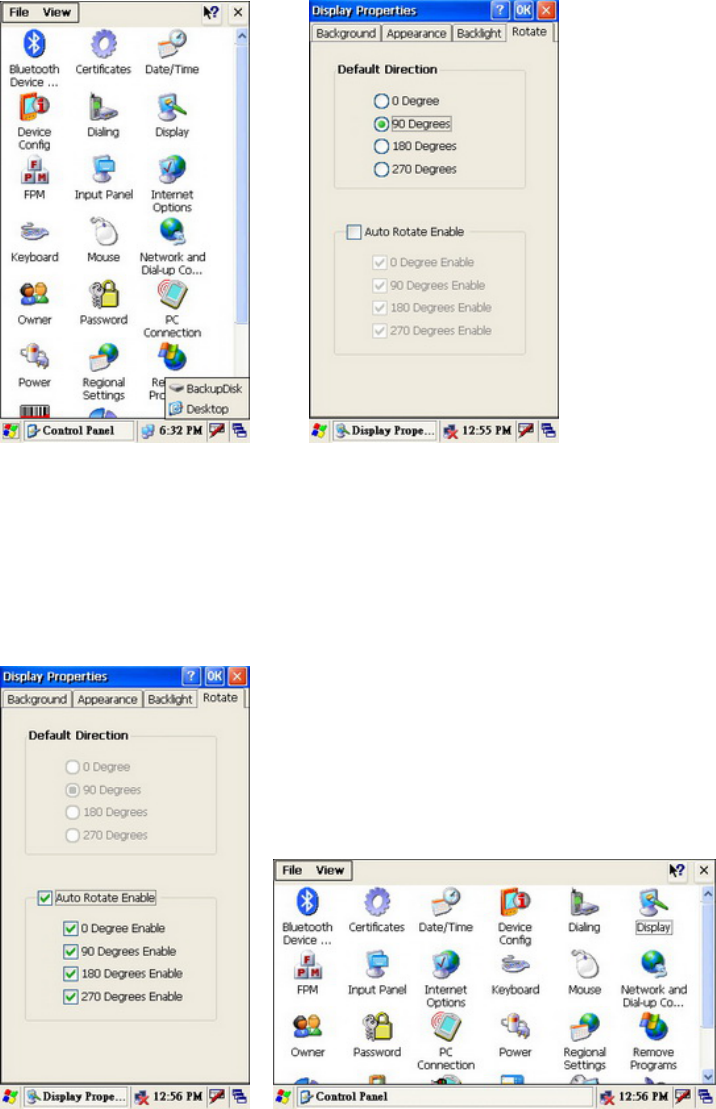
3-6 Display Rotation
1. Open Start > Control Panel
2. Press “Display” icon.
3. Select “Rotate” tab in the “Display Properties” dialog.
4. Check the options you want to set up for the display rotation mode.
5. Display will rotate according to your previous setup.
45
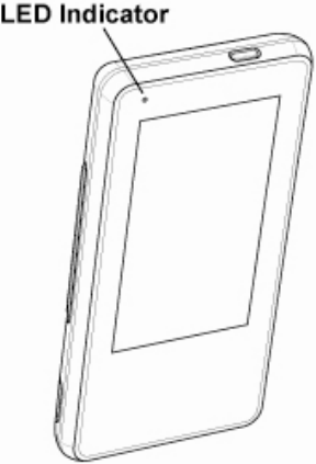
3-7 LED Indicator Description
The LED indicator is located in the front of the Mobile System which
indicates the status. Power on/off , Main Battery and WiFi Link. The
description is as follows:
Green color LED: Battery power charging state
LED ON: Battery power charging finished (100%)
Orange color LED: Battery power charging state
LED ON: Battery power charging
Blue color LED: Link status of WiFi manager
LED ON: WiFi link active
Red color LED: Battery power state
LED Flash: Battery low
LED ON: Critical battery low
46
3-8 Resetting the Mobile System
The mobile system has the ability "Reset to factory default settings" and
"cold boot". The detail procedures as bellows:
3-8-1 Reset to the Factory Default Settings
1. Use a tool to gently press the "Reset Hole" on the rear of the
mobile system while holding down the "Power Button" until the
system vibrates.
2. Keep depressing the power button and press the "Reset Hole"
once, the system them will start the calibration instructions. Finish
the calibration process to complete the "Reset to factory defaults".

47
3-8-2 Cold Boot
Refer to Chapter 3-8-1 for power button and reset hole instructions.
3. Use a tool to gently press the "Reset Hole" on the rear of the
Mobile System while depressing the "Power Button".
4. Release the "Reset Hole" and "Power Button" at the same time
after the system vibrates.
5. The system will reboot to the desktop.
¾ Note: The desktop slightly varies according to the OS
version installed.
48
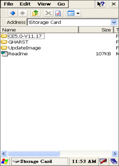
3-9 OS Image Update steps
3-9-1 Unzip the RAR compressed file to Micro SD root directory
You will find two directories from the root directory of Micro SD card which the
directories to be unzipped from RAR file.
File descriptions:
Directory 1: “CE5.0-Vxx.xx” -- WindowsCE 5.0 OS image revision
Including : Eboot.bin -- OS Image loader
nk.bin -- OS Image
Target_m.txt -- Image of system power manager
Directory 2: “UpdateImage” -- Image update tool
Including : OS_DOWNLOAD.exe -- Execution file of Image update tool
OS_DOWNLOAD.cfg -- Configuration file of Image update tool
MCU_UPDATE.exe -- Companion file of Image update tool
FormatPartitionCE5.dll -- WinCE5.0 driver of Image update tool
FormatPartitionCE6.dll -- WinCE6.0 driver of Image update tool
49
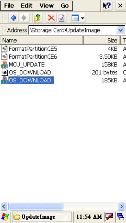
3-9-2 Image update procedures
Execute image update tool
1. Go to “UpdateImage” directory.
2. Double click “OS_DOWNLOAD.exe” icon to run image update tool.
50
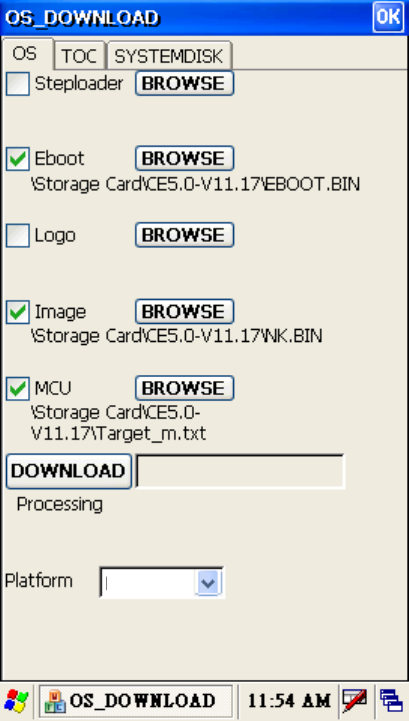
Update OS image
1. Check the settings of the "OS" tab on the OS-Download tool.
2. Click “DOWNLOAD” button to start OS image download procedure
3. Cold boot and reset the system to factory default mode after download
procedure completed
XXXXX
X

51
4 Application Programming Interface
4-1 Windows Embedded CE 5.0 Standard
21BInterface Introduction
Most of the software programming interfaces of the device are as follows.
- Core OS Service
(http://msdn.microsoft.com/en-us/library/aa450512.aspx)
- Kernel
(http://msdn.microsoft.com/en-us/library/aa450998.aspx)
22BProgramming interface of RAM file system
- File system and storage management
(http://msdn.microsoft.com/en-us/library/ms892386.aspx)
23BProgramming interface of Persistent storage
- Folder name: “Backup”
- Block Drivers
(HUhttp://msdn.microsoft.com/en-us/library/ms923712.aspxUH )
- File system and storage management
( HUhttp://msdn.microsoft.com/en-us/library/ms892386.aspxUH )
Programming interface of Secure Digital Card
- Folder name: “Storage Card”
- Secure Digital Card Drivers
(HUhttp://msdn.microsoft.com/en-us/library/ms923739.aspxUH )
- Block Drivers
( HUhttp://msdn.microsoft.com/en-us/library/ms923712.aspxUH )
- File system and storage management
( HUhttp://msdn.microsoft.com/en-us/library/ms892386.aspx UH )

52
25BProgramming interface of Audio
- Audio
( HUhttp://msdn.microsoft.com/en-us/library/ms890653.aspxUH )
- Audio Drivers
( HUhttp://msdn.microsoft.com/en-us/library/aa910103.aspxUH )
26BProgramming interface of Display(LCD)
- Shell and User Interface
( HUhttp://msdn.microsoft.com/en-us/library/aa453940.aspxUH )
- Graphic
( HUhttp://msdn.microsoft.com/en-us/library/ms923392.aspxUH )
- Display Drivers
( HUhttp://msdn.microsoft.com/en-us/library/aa447505.aspxUH )
27BProgramming interface of USB Host
- USB Host Drivers
( HUhttp://msdn.microsoft.com/en-us/library/ms923751.aspxUH )
- Shell, GWES, and User Interface
( HUhttp://msdn.microsoft.com/en-us/library/aa932172.aspxUH )
28BProgramming interface of MSR Reader
29BProgramming interface of USB Slave
- USB Function Drivers
( HUhttp://msdn.microsoft.com/en-us/library/aa931533.aspxUH )
- USB Serial Host Driver (Activesync)
( HUhttp://msdn.microsoft.com/en-us/library/aa932783.aspxUH )
- File system and storage management (Card Reader)
( HUhttp://msdn.microsoft.com/en-us/library/aa914412.aspxUH )
B

53
31BProgramming interface of Wireless
- Network Driver
( HUhttp://msdn.microsoft.com/en-us/library/aa919639.aspxUH )
- Networking - Core
( HUhttp://msdn.microsoft.com/en-us/library/aa917156.aspxUH )
- Networking - Remote
( HUhttp://msdn.microsoft.com/en-us/library/aa920180.aspxUH )
- Networking – Wireless (Wi-Fi)
( HUhttp://msdn.microsoft.com/en-us/library/aa916578.aspxUH )
32BProgramming interface of Touch
- Touch Screen Drivers
( HUhttp://msdn.microsoft.com/en-us/library/aa925927.aspxUH )
- Shell, GWES, and User Interface
( HUhttp://msdn.microsoft.com/en-us/library/aa932172.aspxUH )
33BProgramming interface of Button
- Keyboard Drivers
( HUhttp://msdn.microsoft.com/en-us/library/aa932012.aspxUH )
- Shell, GWES, and User Interface
( HUhttp://msdn.microsoft.com/en-us/library/aa932172.aspxUH )
34BProgramming interface of Vibrator
- Notification LED Drivers
( HUhttp://msdn.microsoft.com/en-us/library/aa925927.aspxUH )
- Shell, GWES, and User Interface
( HUhttp://msdn.microsoft.com/en-us/library/aa932172.aspxUH )
35B

54
Programming interface of System Power
- Battery Drivers (Battery)
( HUhttp://msdn.microsoft.com/en-us/library/aa932396.aspxUH )
- Power Management (Power status – battery/DC)
( HUhttp://msdn.microsoft.com/en-us/library/aa923906.aspxUH )
Programming interface of Power Management
- Power Management
( HUhttp://msdn.microsoft.com/en-us/library/aa923906.aspxUH )
55
4-2 Non WindowsCE Standard
4-2-1 Admin/User Mode Application
Architecture Introduction:
System provides three pair of directories to map the working folder of each
operating mode.
Working folders name of Admin mode
/Windows/Desktop
File folder for saving the shortcut of application program in the Desktop.
/Windows/Programs
File folder for saving the shortcut of application program in the Programs
tab at start menu.
/Windows/StartUp
File folder for saving the shortcut of application program in the StartUp
folder where to be used to auto-run the programs during OS booting
phase .
Working folders name of User mode
/Windows/Desktop_
File folder for saving the shortcut of application program in the Desktop.
/Windows/Programs_
File folder for saving the shortcut of application program in the Programs
tab at start menu.
/Windows/StartUp_
File folder for saving the shortcut of application program in the StartUp
folder where to be used to auto-run the programs during OS booting
phase.
56
Switching between Admin mode and User mode
There is a control box in the control panel applet, -"Password" The default
password is "1111".
Step:
1. Find Password control box from control panel applet.
2. Enter password: “1111” (Default)
3. Select User mode or Admin mode.
4. Type the “OK” button of password properties control box.
5. Type the “OK” button of “Mode Chang” dialog for double confirmation.
6. System would reboot automatically to the selected mode.
How to use this feature?
System integrators only have to copy the desired files to the working
folders of each mode.
It is impossible to change the operation mode by resetting the system to
factory defaults.
In case the user forget the password. The only way to retrieve the
password is to run the Manufacturer maintenance application by copying
the application to a SD card and cold resting the device.
Step:
1. Copy the desired files to the working folder of the operation mode
2. Follow Section “Switch the operation mode between Admin mode and
User mode” to switch operation mode.

57
4-2-2 Overwrite Factory Default
Architecture Introduction:
The Manufacturer provides a mechanism to merge the OEM application
and OEM specific settings into WindowCE operating system during booting
phase. This feature can make OEM stuffs as system default components.
There are many benefits for device maintenance.
It is a valuable feature for OEM doesn’t have to reinstall OEM programs
after end user reset the device to factory default mode. This benefit also
helps to reduce the RMA cost from OEM vender.
Because of this system architecture, WindowCE operating system and
OEM application programs are not merged together. So both parts can be
upgraded separately.
Architecture of the OEM Device Manager
System Integrator should base on the directory structure of WindowCE to
prepare the OEM installation files in SD card. All files in “GHARST” file
directory would be copy into WindowCE file system during cold booting
phase. By the way, the config files in “configfiles” directory are for system
registry maintenance.
GHARST
Configfiles
Oem.cfg
System.cfg
Windows
Program Files
My Documents
Documents and Settings
Temp
58
Merge an application program into default operating system
by using the OEM Device Manager
Example:
- For Auto-running the OEM application at booting phase of user
mode when after reset to factory default.
1. Create a file directory “GHARST” in root folder of SD card.
2. Change into “GHART” folder to create directory “Windows”.
3. Change into “Windows” folder to create directory “StartUp_”.
4. Copy the OEM application file into “Windows->StartUp_” folder.
[Second way is: copy OEM application file into “Windows” folder,
creates a lnk file of OEM application and copy it into
“Windows->StartUp_” folder.
5. Put SD card into the SD socket on the device.
6. Use OEM The device Manager to merge all files in “GHARST” folder in
SD card into the device. After the file integration process, all OEM
specify files will be the system default components of the device.
- Place the OEM application at “Programs” folder in Windows Start
menu - System running in user mode.
1. Create a file directory “GHARST” in root folder of SD card.
2. Change into “GHART” folder to create directory “Windows”.
3. Change into “Windows” folder to create directory “Programs_”.
4. Copy the OEM application file into “Windows->Programs_” folder.
[Second way is: copy OEM application file into “Windows” folder,
creates a lnk file of OEM application and copy it into
“Windows->Programs_” folder]
5. Put SD card into the SD socket on the device.
6. Use OEM The device Manager to merge all files in “GHARST” folder in
SD card into the device. After the file integration process, all OEM
specify files will be the system default components of the device.
How to overwrite the factory default settings by using the
OEM Device Manager
Two config files are used to modify the registry settings of factory default
mode. System Integrator is easy to add and/or modify the registry key
without upgraded the image of WindowsCE operating system. The way to
59
remove the registry key is to put empty to the key value in the config file.
System.cfg – Using for early registry initialization stage at booting phase.
Oem.cfg – Using for system registry initialization stage at booting phase.
Example:
- Overwrite the factory default backlight level setting.
1. Create a file directory “GHARST” in root folder of SD card.
2. Change into “GHART” folder to create directory “configfiles”.
3. Prepare the oem.cfg config file by text editor.
Input following setting:
[HKEY_CURRENT_USER\ControlPanel\BackLight]
"BatteryBacklightLevel"=dword:7
"ACBacklightLevel"=dword:A
4. Copy oem.cfg file into “configfiles” folder.
5. Put SD card into the SD socket on device.
6. Use OEM Device Manager to merge all files in “GHARST” folder in SD
card into device. After the integration process, all OEM desired settings
will be the system default settings of device.
- Overwrite the default WiFi state to power on mode. (Default is
power down)
1. Create a file directory “GHARST” in root folder of SD card.
2. Change into “GHART” folder to create directory “configfiles”.
3. Prepare or modify the oem.cfg config file by text editor.
Input following setting:
[-HKEY_LOCAL_MACHINE\Comm\NdisPower]
4. Store oem.cfg file into “configfiles” folder.
5. Put SD card into the SD socket on device.
6. Use the OEM device manager to merge all files in “GHARST” folder in
SD card into device. After the integration process, all OEM desired
settings will be the system default settings of device.
- Remove a registry key from the registry in factory default settings
Set the key to empty. Factory manager will remove the specific key from
the default system registry.
Example:
[HKEY_LOCAL_MACHINE\RegistryKey]
"ValueName"=
60
Overwrite Factory Default Registry Settings for OEM
Customization (oem.cfg)
<1> Bluetooth operating mode
[HKEY_LOCAL_MACHINE\System\State\Hardware\Bluetooth]
“BluetoothOn”=dword:1 ; 1-> BT on, 0->BT off
“BluetoothWakeUpEnable”=dword:0 ;1-> Enable, 0-> Disable
<2> WiFi operating mode is off
[HKEY_LOCAL_MACHINE\Comm\NdisPower]
“GSPI86861”=dword:4 ; 4->WiFi off
WiFi operating mode is on
[-HKEY_LOCAL_MACHINE\Comm\NdisPower]
[HKEY_LOCAL_MACHINE\Comm\GSPI86861\Parms]
“PowerMode” = dword:1 ; 0: Performance mode, 1: PS mode
“MultipleDTim”=dowrd:2 ; PS mode (0,1,2,3,4 –most power
saving)
<3> Screen rotation feature
[HKEY_LOCAL_MACHINE\System\GDI\Rotation]
“Angle”=dword:1 ;(Decimal 0->0 degree, 90->90 degree, 180->180
degree, 270->270 degree) // Manual rotate mode
“AutoRotate”=dword:F // Auto Rotate control
; bit 15 = 0 (Manual rotate) = 1 (Auto Rotate)
; bit 0 = 0 (180 degree ignored) = 1 (180 degree accepted)
; bit 1 = 0 (90 degree ignored) = 1 (90 degree accepted)
; bit 2 = 0 (0 degree ignored) = 1 (0 degree accepted)
; bit 3 = 0 (270 degree ignored) = 1 (270 degree accepted)
<4> Backlight control
[HKEY_CURRENT_USER\ControlPanel\BackLight]
"BatteryBacklightLevel"=dword:7 // Backlight level of battery only
"ACBacklightLevel"=dword:A // Backlight level of AC IN mode
"BatteryTimeout"=dword:3c // Backlight timeout value of battery
only mode
"ACTimeout"=dword:258 // Backlight timeout value of AC IN
mode
"DimTimeOut"=dword:1E // Backlight DIM mode timeout
61
"UseBattery"=dword:0 // Battery only mode timeout
Enable/Disable
"UseExt"=dword:0 // AC IN mode timeout Enable/Disable
"UseDim"=dword:0 // Backlight DIM mode
Enable/Disable
<5> CPU operating frequency control
Option1: Dynamic Mode
[HKEY_LOCAL_MACHINE\Drivers\BuiltIn\IPM]
"ProfileType"=dword:0
Option2: Performance Mode
[HKEY_LOCAL_MACHINE\Drivers\BuiltIn\IPM]
"ProfileType"=dword:1
"Speed"=dword:0
Option3: Power Saving Mode
[HKEY_LOCAL_MACHINE\Drivers\BuiltIn\IPM]
"ProfileType"=dword:1
"Speed"=dword:4
62
Application program of the OEM Device Manager
System Layer : “system.cfg” file update
OEM Layer : “oem.cfg” file update
Press “OK” button to merge the GHARST directory and specified layer
config files into OS image
Snapshoot of OEM Device Manager
63
Overwrite display backlight settings
Once the backlight is enables, you can set both battery and AC power
settings for the backlight. System Integrators can use the Control Panel
to change the setting values or modify the following registry keys to change
the settings. Note the units for the timeout values are in seconds.
Registry Key:
[HKEY_CURRENT_USER\ControlPanel\Backlight]
Modify display backlight settings for AC power
Values:
- UseExt : 1 (Enable/default) / 0 (Disable)
- ACTimeout : 15/30/60/120/300/600(default)/900/1800
- ACBacklightLevel : 0/1/2/3/4/5/6/7/8/9/10(default)
Modify display backlight settings for battery power
Values:
- UseBattery : 1 (Enable/default) / 0 (Disable)
- BatteryTimeout : 15/30/60(default)/120/300
- BatteryBacklightLevel : 0/1/2/3/4/5/6/7(default)/8/9/10
Modify display backlight settings for DIM mode
Values:
- UseDim : 1 (Enable/default) / 0 (Disable)
- DimTimeout : 15/30(default)/60/120/300
Example Code (Update backlight level)
void UpdateRegistry(DWORD dwVal)
{
TCHAR szRegClass[] = TEXT("DWORD");
HKEY hRegBacklight;
DWORD dwDisposition;
if(ERROR_SUCCESS ==
RegCreateKeyEx(HKEY_CURRENT_USER, L"ControlPanel\\Backlight", 0,
szRegClass, REG_OPTION_NON_VOLATILE, 0, NULL, &hRegBacklight,
&dwDisposition))
{
LONG lResult;
DWORD dwType = REG_DWORD;
64
DWORD dwLen = sizeof(DWORD);
// Battery Level
lResult = RegSetValueEx(hRegBacklight,
L"BatteryBacklightLevel", 0, dwType, (LPBYTE)&dwVal, dwLen);
// AC Level
lResult = RegSetValueEx(hRegBacklight, L"AcBacklightLevel", 0,
dwType, (LPBYTE)&dwVal, dwLen);
}
RegCloseKey(hRegBacklight);
}

65
4-2-3 Vibration notification feature
This device is designed with a vibration motor for notification. The driver
follows the LED driver architecture of WindowCE. This architecture uses
WindowCE NLED standard API for application development.
Data Structure introduction
struct NLED_SETTINGS_INFO
{
UINT LedNum;
INT OffOnBlink;
LONG TotalCycleTime;
LONG OnTime;
LONG OffTime;
INT MetaCycleOn;
INT MetaCycleOff;
};
LedNum
LED number. Virbrator is zero (0).
OffOnBlink
Current setting. The following table shows the defined values.
Value Description
0 Off
1 On
2 Blink
TotalCycleTime
Total cycle time of a blink, in microseconds. (Not support – default 0)
OnTime
On time of the cycle, in microseconds. (Not support – default 0)
OffTime
Off time of the cycle, in microseconds. (Not support – default 0)
MetaCycleOn
Number of on blink cycles. (Not support – default 0)
MetaCycleOff
Number of off blink cycles. (Not support – default 0)
66
Example code
#include "stdafx.h"
NLED_SETTINGS_INFO ledSettingsInfo = { 0 };
void SetVibratorOn(void)
{
ledSettingsInfo.LedNum = 0;
ledSettingsInfo.OffOnBlink = 0;
if(!NLedSetDevice(NLED_SETTINGS_INFO_ID,&ledSettingsInfo))
MessageBox(L"NLED ghNLED = NULL!!",L"Error",MB_OK);
}