FMS Force Measurnig Systems E310COMACT DMS Measuring Amplifier User Manual EMGZ310 EN A4 16 10 05x
FMS Force Measurnig Systems AG DMS Measuring Amplifier EMGZ310 EN A4 16 10 05x
UserManual.pdf
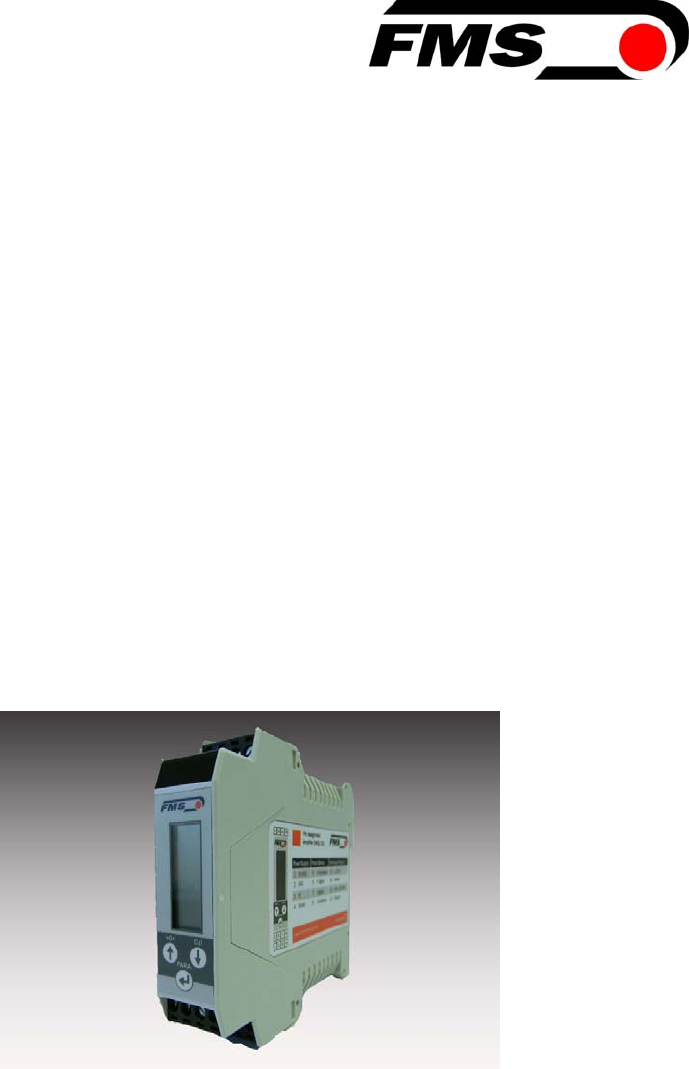
Operating Manual
EMGZ310
Digital Microprocessor Controlled Tension Amplifier
EMGZ310.ComACT
Digital Microprocessor Controlled Tension Amplifier
with intuitive operation via FMS ComACTTM app
Version 2.10 10/2016 NS
Firmware Version EMGZ310 V1.14
Firmware Version EMGZ310.ComACT V2.10
This operation manual is also available in German.
Please contact your local FMS representative.
Diese Bedienungsanleitung ist auch in Deutsch erhältlich.
Bitte kontaktieren Sie Ihren nächstgelegen FMS Vertreter.
© by FMS Force Measuring Systems AG, CH-8154 Oberglatt – All rights reserved.

Operating Manual EMGZ310 and EMGZ310.ComACT
10.01.2017 2
Table of contents
1Safety Instructions ..................................................................................... 3
1.1Description conditions 3
1.2List of safety instructions 4
1.3Regulatory Notices 5
1.4Notes Réglementaires 6
2Quick Installation Guide ............................................................................ 7
2.1Preparations for Set-up 7
2.2Installation Procedure 7
2.3Mounting the Force Sensors 7
2.4Installation and wiring 7
2.5Block diagram 8
2.6Wiring the Amplifier 8
2.7Modify the wiring 9
3Configuring the Amplifier ....................................................................... 10
3.1Power up the EMGZ 310 10
3.2Operating the EMGZ310 over the Operating Panel 10
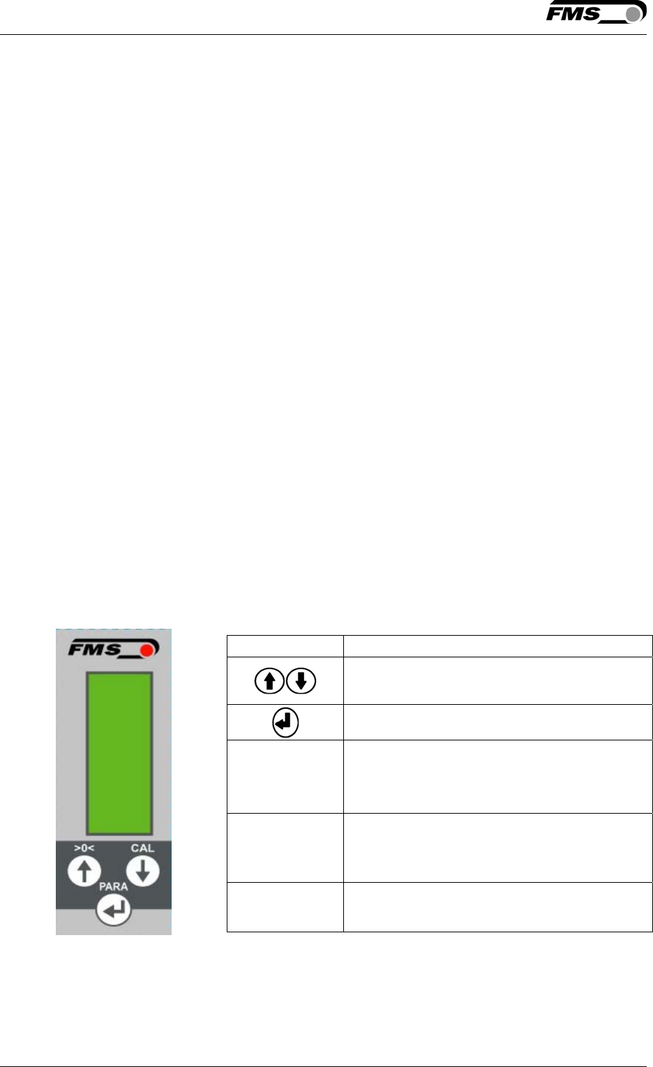
3.3Operating Panel 10
3.4Change the Device Mode 11
3.5Offset Compensation 11
3.6Calibration 12
3.7Calibration Procedure in the Force Gauge Mode 13
3.8Calibration Procedure in Volt Gauge Mode 14
4Configuration via operating panel ......................................................... 15
4.1Reset to Default Parameter Set 17
4.2Parameter List 18
4.3Description of Parameters 19
5Configuration via FMS ComACTTM app .................................................. 22
5.1Screenshots 23
6Dimensions .............................................................................................. 24
7Technical Specification ........................................................................... 25
8Your Settings ............................................................................................ 26
9Notes ......................................................................................................... 27
Operating Manual EMGZ 310
10.01.2017 3
1 Safety Instructions
All safety related regulations, local codes and instructions that appear in the
manual or on equipment must be observed to ensure personal safety and to
prevent damage to the equipment connected to it. If equipment is used in a
manner not specified by the manufacturer, the protection provided by the
equipment may be impaired. Do not stress the equipment over the specification
limits neither during assembly nor operation. To do so can be potentially harmful
to persons or equipment in the event of a fault to the equipment.
1.1 Description conditions
a) High danger of health injury or loss of life
Danger
This symbol refers to high risk for persons to get health injury or loss of life. It has
to be followed strictly.
b) Risk of damage of machines
Caution
This symbol refers to information, that, if ignored, could cause heavy mecanical
damage. This warning has to be followed absolutely.
c) Note for proper function
Note
This symbol refers to an important information about proper use. If not followed,
malfunction can be the result.

Operating Manual EMGZ310 and EMGZ310.ComACT
10.01.2017 4
1.2 List of safety instructions
Proper function of the Tension Measuring Amplifier is only guaranteed with the
recommended application of the components. In case of other arrangement,
heavy malfunction can be the result. Therefore, the installation instructions on
the following pages must be followed strictly.
Local installation regulations are to preserve safety of electric equipment. They
are not taken into consideration by this operating manual. However, they have to
be followed strictly.
Bad earth connection may cause electric shock to persons, malfunction of the
total system or damage of the control unit. It is vital to ensure a proper earth
ground connection.
Each change of the Device Mode requires a re-calibration of the system
Changes or modifications made to this equipment not expressly approved by FMS
AG may void the FCC authorization to operate this equipment.
Operating Manual EMGZ 310
10.01.2017 5
1.3 Regulatory Notices
NOTE:
This device complies with Part 15 of the FCC Rules and with Industry Canada
licence-exempt RSS standard(s).
Operation is subject to the following two conditions:
this device may not cause harmful interference, and
this device must accept any interference received, including interference
that may cause undesired operation.
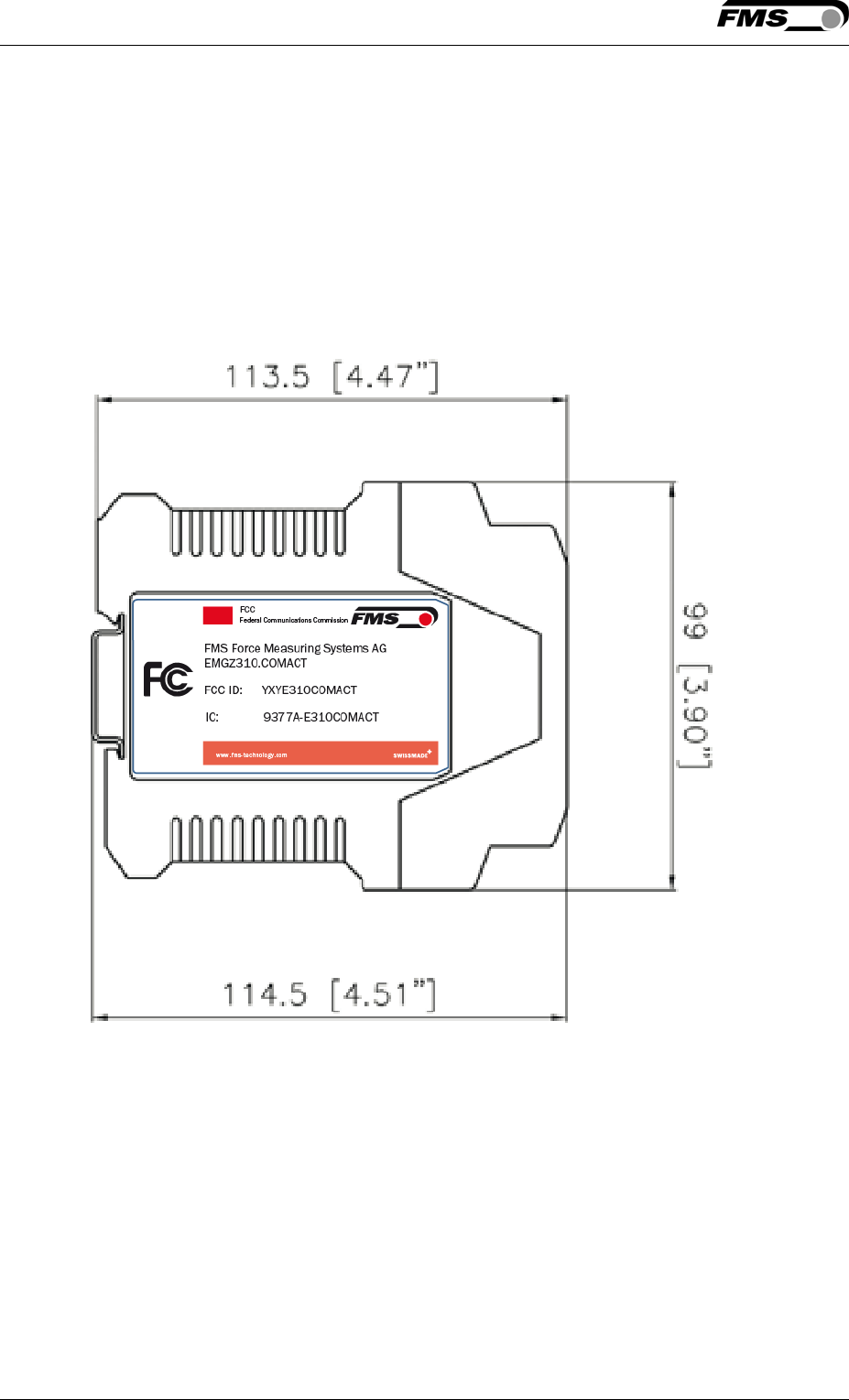
Fig. 1a: FCC labeling on device FCC_Label_EMGZ310ComACT.ai
NOTE:
This equipment has been tested and found to comply with the limits for a Class A
digital device, pursuant to Part 15 of the FCC Rules. These limits are designed to
provide reasonable protection against harmful interference when the equipment is
operated in a commercial environment. This equipment generates, uses, and can
radiate radio frequency energy and, if not installed and used in accordance with
the instruction manual, may cause harmful interference to radio communications.
Operation of this equipment in a residential area is likely to cause harmful
interference in which case the user will be required to correct the interference at
his own expense.

Operating Manual EMGZ310 and EMGZ310.ComACT
10.01.2017 6
NOTE:
Changes or modifications made to this equipment not expressly approved by FMS
Force Measuring Systems AG may void the FCC authorization to operate this
equipment.
Radiofrequency radiation exposure Information:
This equipment complies with FCC and IC radiation exposure limits set forth for an
uncontrolled environment. This equipment should be installed and operated with
minimum distance of [50] cm between the radiator and your body.
This transmitter must not be co-located or operating in conjunction with any other
antenna or transmitter.
1.4 Notes Réglementaires
NOTE:
Cet équipement est conforme à la section 15 du règlement de la Commission
fédérale américaine des communications (FCC) et au(x) Cahier(s) des charges sur
les normes radioélectriques (CNR) d’Industrie Canada exemptes de licence.
Son utilisation est soumise aux deux conditions ci-dessous :
cet équipement ne peut pas causer d’interférences nuisibles, et
cet équipement doit accepter toutes les interférences, y compris celles qui
pourraient provoquer un fonctionnement indésirable.
NOTE:
Cet équipement a été testé et déclaré conforme aux limites applicables aux
appareils numériques de classe A, selon la section 15 du règlement FCC. Ces
limites visent à garantir une protection raisonnable contre les interférences
nuisibles lorsque l’équipement est utilisé dans un environnement commercial.
Cet équipement produit, utilise et peut émettre une énergie de fréquence radio et,
s’il n’est pas installé ni utilisé conformément au manuel d’instruction, il peut
générer des interférences affectant les communications radio. L’utilisation de cet
équipement dans une zone résidentielle peut causer des interférences nuisibles,
auquel cas l’utilisateur sera tenu d’y remédier à ses frais.
NOTE:
Des changements ou modifications apportés à cet équipement sans l’autorisation
expresse de FMS Force Measuring Systems AG peuvent invalider l’agrément
d’utilisation de cet équipement accordé par la FCC.
Informations sur l’exposition aux rayonnements radioélectriques
Cet équipement est conforme aux limites d'exposition aux rayonnements IC
établies pour un environnement non contrôlé. Cet équipement doit être installé et
utilisé avec un minimum de
[50] cm de distance entre la source de rayonnement et votre corps.
Ce transmetteur ne doit pas etre place au meme endroit ou utilise simultanement
avec un autre transmetteur ou antenne. “

Operating Manual EMGZ 310
10.01.2017 7
2 Quick Installation Guide
In a Plug & Play configuration the set-up of the EMGZ310 and force sensor is limited to
only the offset compensation and the calibration.
2.1 Preparations for Set-up
1. Read the Operation Manual of your force measuring sensors
2. Check your requirements such as:
− Desired output configuration ±10V or 0/4… 20mA
− Devise Mode (Force Gauge or Volt Gauge)
− Cut off frequency of low-pass filter
3. Draw the wiring diagram for your configuration (ref. to 2.6 “Wiring the
Amplifier“)
2.2 Installation Procedure
1. Mount your force maesuring sensors to the machine
2. Wire the Force Measuring Sensor(s) (ref. to Fig. 1 and 2)
3. Connect the amplifier to the power supply.
4. The power supply voltage must be in the range 18 to 36V DC.
5. Perform offset compensation and calibration (ref. to chapters 3.4 to 3.7)
6. If required, do additional settings (ref. to 4 “ Parameterization”)
2.3 Mounting the Force Sensors
Mounting of the force sensors is done according to the FMS Installation manual
which is delivered together with the force sensors.
2.4 Installation and wiring
Caution
Proper function of the Tension Measuring Amplifier is only guaranteed with the
recommended application of the components. In case of other arrangement,
heavy malfunction can be the result. Therefore, the installation instructions on the
following pages must be followed strictly.
Caution
Local installation regulations are to preserve safety of electric equipment. They
are not taken into consideration by this operating manual. However, they have to
be followed strictly.
Operating Manual EMGZ310 and EMGZ310.ComACT
10.01.2017 8
2.5 Block diagram
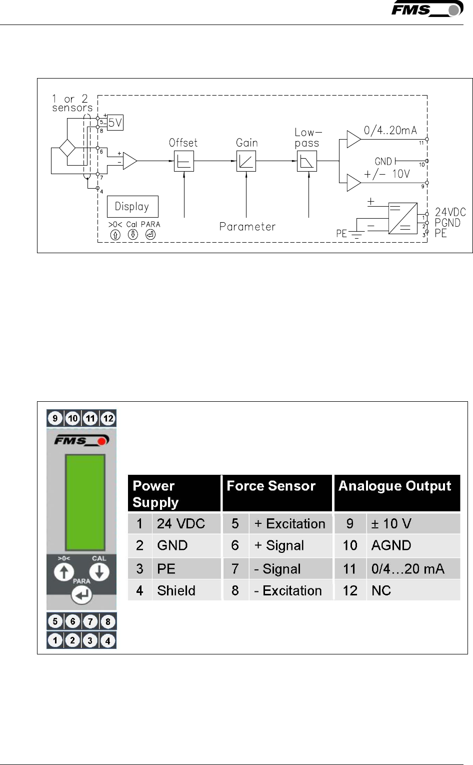
Fig. 1: Block diagram EMGZ 310 E310001e
2.6 Wiring the Amplifier
One or two force sensors can be connected to the measuring amplifier. When
using two force sensors, the output signal of the measuring amplifier will then
correspond to the average value of the two sensors. The connection between force
sensors and measuring amplifier has to be done using a 2x2x0.25mm2 [AWG 23]
shielded twisted-pair cable.
Fig. 2: Wiring of EMGZ 310 E310002e
Operating Manual EMGZ 310
10.01.2017 9
Caution
Bad earth connection may cause electric shock to persons, malfunction of the
total system or damage of the control unit. It is vital to ensure a proper earth
ground connection.
Note
The shield should be connected only to the electronic unit. On the force sensor
side the shield should stay open.
Note
Sensor cables must be installed separate from power lines.
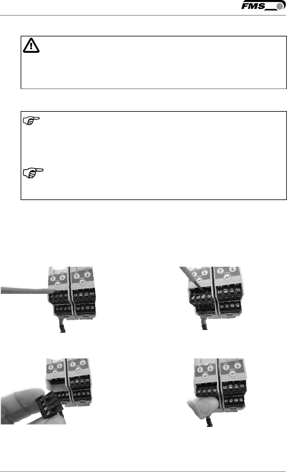
2.7 Modify the wiring
For an easy and quick exchange of an amplifier it is possible to exchenge the
single terminal blocks as assembly. You neither have to disconnect the wiring,
nore do you have to open the housing of the device.
Make sure that the amplifier is disconnected from the power supply.
Insert a screw driver with a small blade in
between the terminal block and the housing on
the top end of the block
Using the screw driver as a lever will loosen the
block from the housing. It will slide downwards
The block is now disconnected. You can slide it
out the device.
Insert the block on the desired position. Push
the block fully into the slot. You will hear a
“click” sound as the block interlocks
Operating Manual EMGZ310 and EMGZ310.ComACT
10.01.2017 10
3 Configuring the Amplifier
3.1 Power up the EMGZ 310
1. Connect the first force sensor (see Fig.2 Wiring Diagram EMGZ310)
2. Check whether applying a force in measuring direction (in the direction of the
red point) on the first sensor results in a positive output signal. If not, exchange
the two signal wires of this force sensor in the terminal block (terminals 6/7).
3. If applicable, connect the second force sensor.
4. Check whether applying a force in measuring direction on the second sensor
results in a positive output signal. If not, exchange the two signal wires of this
force sensor in the terminal block (terminals 6/7).
3.2 Operating the EMGZ310 over the Operating Panel
The EMGZ310 amplifier can go in 4 different states:
Operation State: Amplifier operating
Offset Compensation: Automatic procedure to offset the roller weight
Calibration State: Procedure to calculate the amplifier gain
Parameterisation State: Set or change parameters
When using the operating panel, the user can toggle between these modes by
pressing a key or a combination of keys.
3.3 Operating Panel
The keys on the operation panel have the following functions:
Fig. 3: Operating
Panel EMGZ 310
E310003
Key Key Function
Change the selections, increase /
decrease the values or choose
Enter
>0< + PARA
Enter Offset Compensation Procedure.
Press the two keys at the same time for
longer than 3 sec.
Cal + PARA
Enter Calibration Procedure. Press the
two keys at the same time for longer
than 3 sec.
PARA Enter the Parameter Setting Mode. Press
the key for longer than 3 sec.
Operating Manual EMGZ 310
10.01.2017 11
3.4 Change the Device Mode
The EMGZ310 amplifier has two Device Modes:
● Display of Force Gauge: Tension data are displayed in a force unit
● Display of Voltage Gauge: Tension data are displayed in Volt (V)
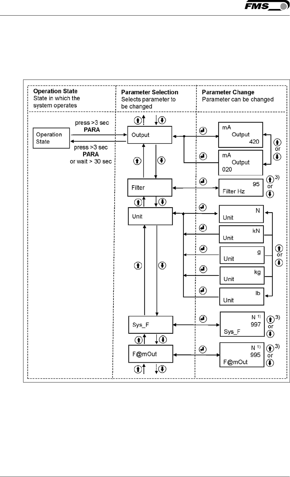
1. Press the PARA key for longer than 3 seconds, to enter the
parameter-selection mode. The display changes to
2. Scroll down the parameter list with the keys until you see on the LCD
3. Press the key to enter the Parameter Chang Mode
4. Select V for Voltage Gauge or kgkNN for Force Gauge
5. Confirm the parameter change with the key
6. Leave the Parametrisation by holding the key for longer than 3 sec.
Caution
Each change of the Device Mode requires a re-calibration of the system
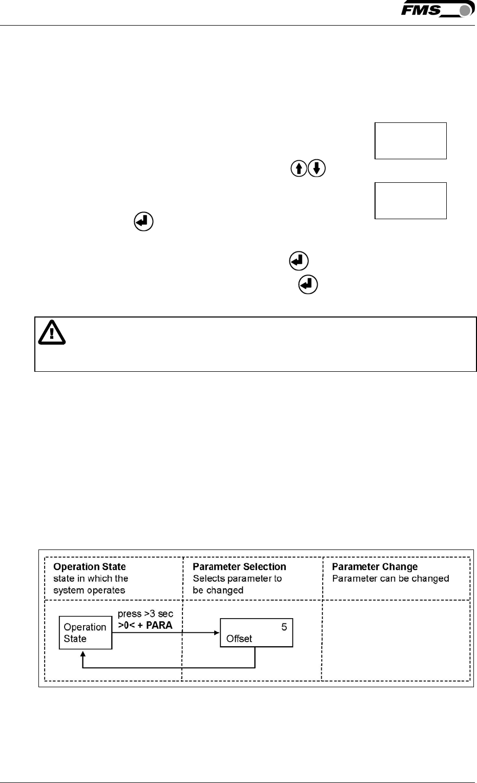
3.5 Offset Compensation
With the Offset Compensation the roller weight is compensated. It is always
performed before the calibration. The Force Measuring Sensor should not be
loaded while the Offset Compensation is performed.
1. Start offset compensation by pressing the two keys >0< + PARA at
the same time for longer than 3 seconds.
2. The offset compensation is done automatically.(see state diagram Fig.4)
Fig. 4: State diagram offset compensation EMGZ310008e
Output
Mode
Operating Manual EMGZ310 and EMGZ310.ComACT
10.01.2017 12
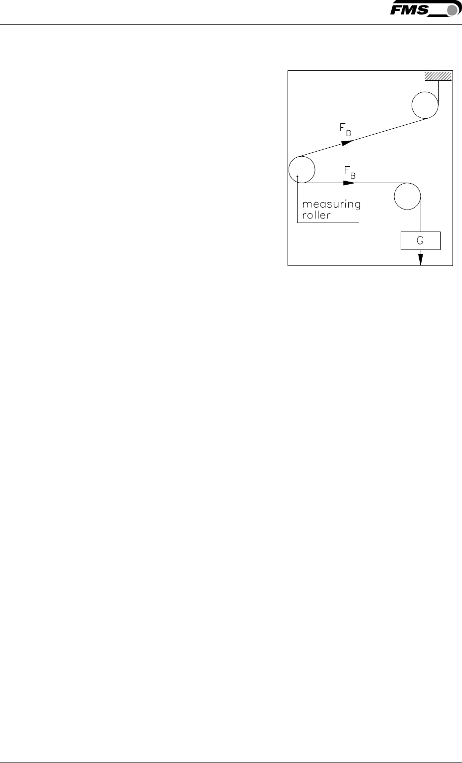
3.6 Calibration
By calibrating (setting the Gain), amplifier
and force sensors are adjust so that the
display gives the actual tension value. There
are two methods of calibrating the system.
The first method uses a defined weight
attached at a rope (see Fig. 5). The second
method is based on a calculation process in
conjunction with the FMS Calculator tool. The
method with the calibration weight is
preferred since it simulates the real material
path in the machine and delivers the most
accurate results.
If the material tension cannot be simulated
in the machine by the weight method (e.g.
because of space restrictions), the gain can
be calculated with the FMS Calculator tool.
This Calculator can be down loaded from the FMS web page.
Fig. 5: Calibrating the
measuring amplifier C431011e
Operating Manual EMGZ 310
10.01.2017 13
3.7 Calibration Procedure in the Force Gauge Mode
Note
If you do not press any key on the operating panel the display will automatically
switch to the intitial screen. You have to repeat any previously performed steps.
Execute the single steps uninterrupted and prepare any required material in advance.
1. Load a rope with a defined weight corresponding to your calibration force on the
roller. The roller configuration must correspond to the real configuration in the
machine (wrap angle, distance of the rollers etc.).
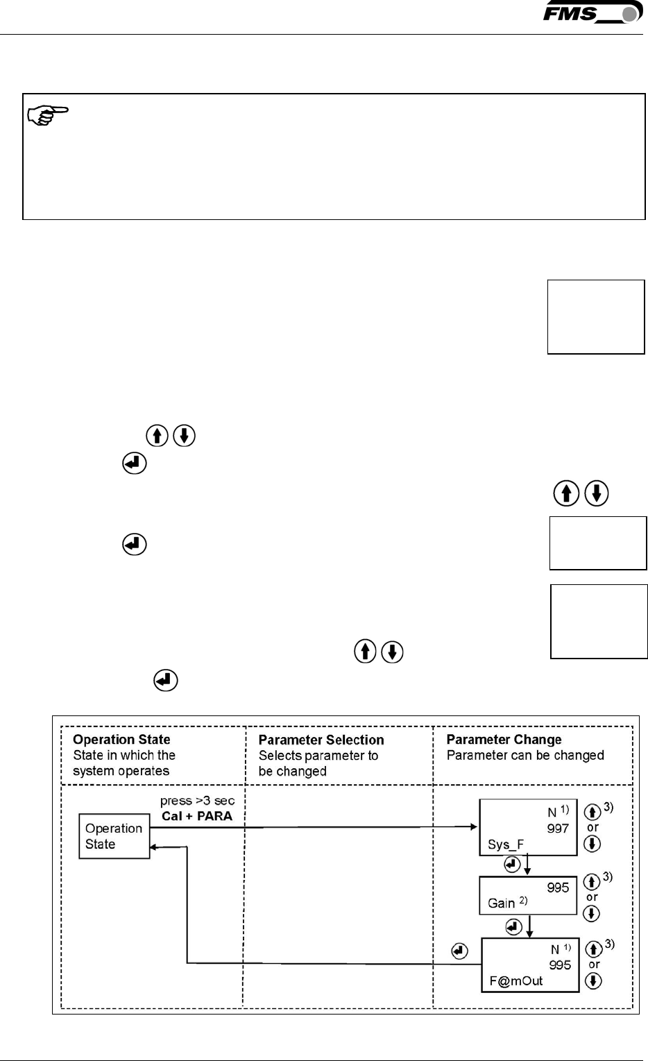
2. Enter calibration mode by pressing the two keys Cal and PARA at
the same time for longer than 3 seconds. The display changes to
3. The System Force [Sys_F] determines the measuring capability of your measuring
roller. E.g. if two 500 N sensors are installed, enter 1000N. If only one 500N
sensor is used, enter 500N (see chapter 4.3 “Descriptions of Parameter”, [Sys_F]).
4. Use the keys to enter the system force. The LCD shows:
5. Press the key to confirm your input.
6. Enter the force corresponding to your calibration weight with the keys
7. Press the key to confirm your input. The display changes t
8. The parameter [F@mOut] determines the force corresponding to the
maximum amplifier output (10V or 20mA) (see chapter 4.3)
9. Enter the value of [F@mOut] with the keys and confirm your
input with the key. The calibration procedure has been completed successfully.
Fig. 6: State diagram calibration EMGZ310009e
N
1000
Sys_F
1000
Gain
N
1000
F@mOut
Operating Manual EMGZ310 and EMGZ310.ComACT
10.01.2017 14
1) The display shows the unit of measure that was previously selected.
2) Enter the force corresponding to your calibration weight
3) Permanent key pressing expedites the changing speed.
3.8 Calibration Procedure in Volt Gauge Mode
1. Load a rope with a defined weight corresponding to your calibration force on the
roller. The roller configuration must correspond to the real configuration in the
machine (wrap angle, distance of the rollers etc.).
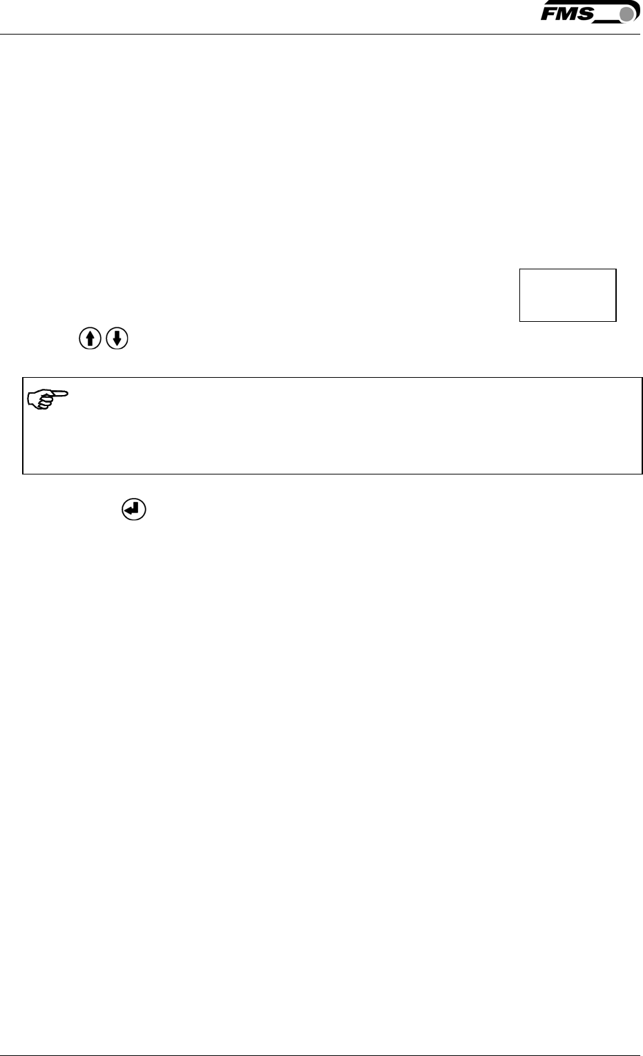
2. Enter calibration mode by pressing the key Cal + PARA for longer than 3 seconds.
The display changes to
3. Use keys to change the output to the correct value, corresponding to the
calibration force.
Note
The force corresponding to the calibration weight must be inputted in Volt (V) in the
following calibration procedure (Volt Gauge).
4. Press the key to confirm the input. The calibration procedure has been
completed successfully.
V 7.4
Gain
Operating Manual EMGZ 310
10.01.2017 15
4 Configuration via operating panel
After having done the offset and calibration procedures the system is configured
and ready for operation. Description of parameterization:
1. Press the key PARA for longer than 3 seconds, to enter the
parameter-select mode. The display changes to
2. Use keys to select the parameter to be changed.
3. Press the key to enter the parameter changing mode.
Use keys to change the parameter value.
4. Press the key to confirm the input. The display changes
back to the parameter-select mode.
5. If needed, press keys to select another parameter.
6. To leave the parameterization, press the key PARA for longer then 3 seconds
or wait for the timeout after 30 seconds, the parameters will be saved then.
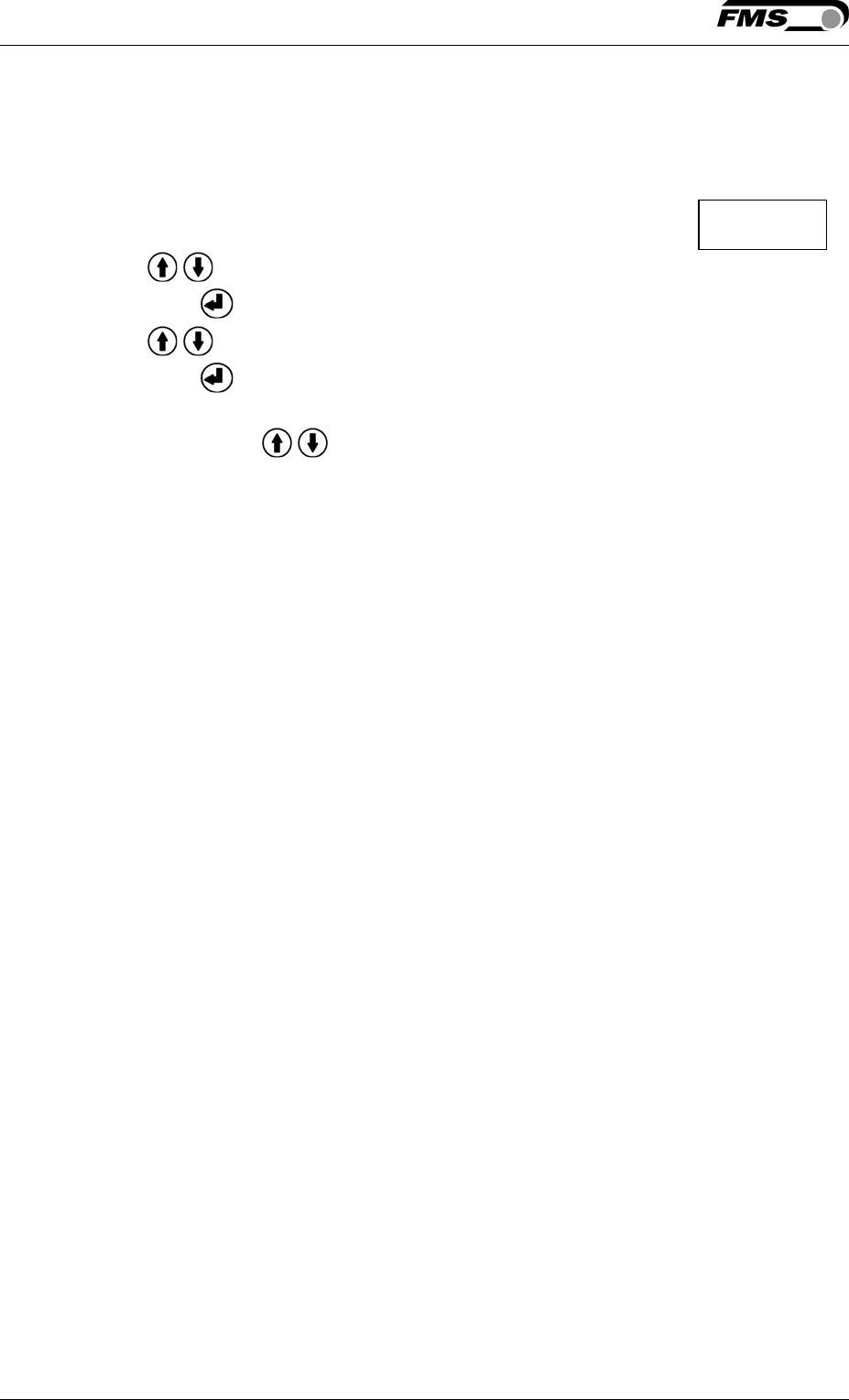
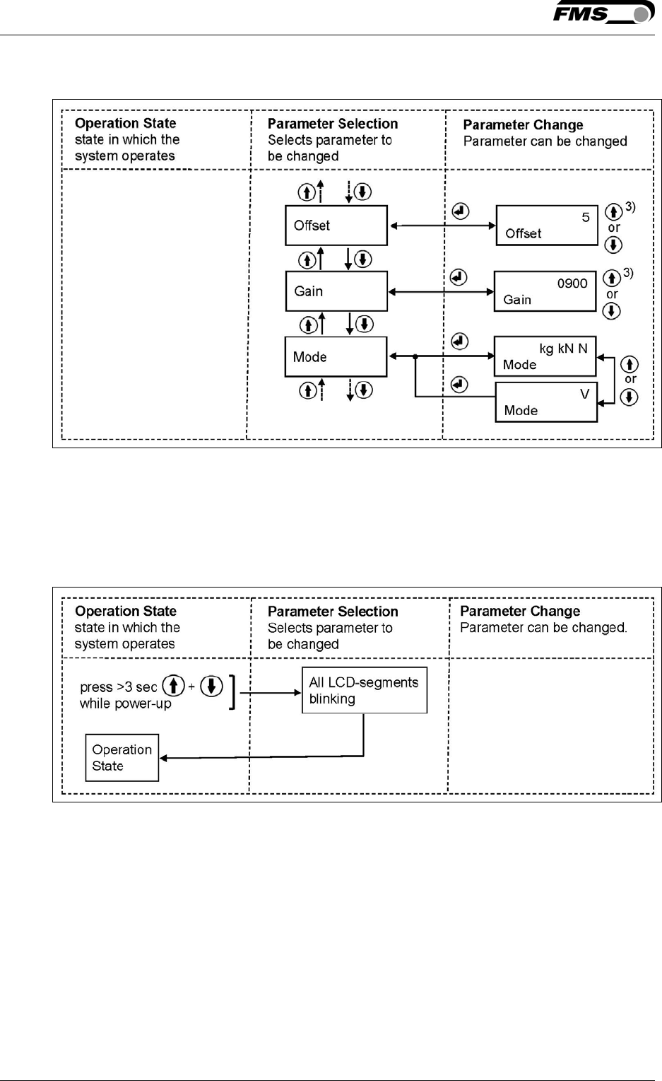
The state diagrams (Fig. 6 -7) in the following page help to navigate through the
parameter setting menu.
Output
Operating Manual EMGZ310 and EMGZ310.ComACT
10.01.2017 16
In the Parameterisation State the EMGZ 310 can be brought into the 2 modes:
“Parameter Selection” and “Parameter Change”.
Fig. 6: State Diagram Parameter Setting (1st part) E310010e
1) The display shows the unit of measure that was previously selected.
2) Enter the force corresponding to your calibration weight
3) Permanent key pressing expedites the changing speed.
Operating Manual EMGZ 310
10.01.2017 17
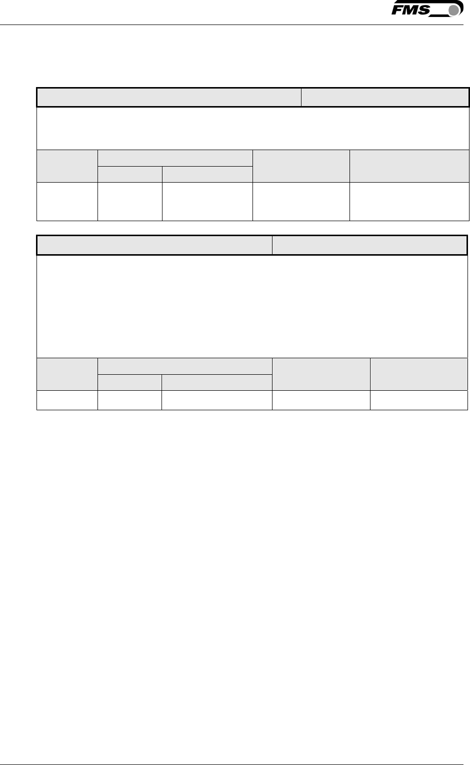
Fig. 7: State Diagram Parameter Setting (2nd part) E310011e
4.1 Reset to Default Parameter Set
Fig. 8: Reset to Default Parameter Set E310012e

Operating Manual EMGZ310 and EMGZ310.ComACT
10.01.2017 18
4.2 Parameter List
Parameter Unit Min Max Default Remarks
Output [mA] 0...20 or 4...20 4…20 Current output
Filter [Hz] 0.1 999.9 10.0 Noise filter
Unit [-] N; kN; g; kg; or lb N System unit
Sys_F N; kN; g;
kg; or lb
1 100’000 1000 System force of
the roller
F@mOut N; kN; g;
kg; or lb
1 100’000 Force at max.
output
Offset [Digit] –8000 8000 8000 Roller weight
Gain [-] 0.1 20.0 20.0 Amplification
Mode [-] Volt or Force Force Requires new
calibration
Operating Manual EMGZ 310
10.01.2017 19
4.3 Description of Parameters
Current Output Selection LCD: .Output
Use: This parameter selects the current output signal of the amplifier. The
voltage output (+/-10V) is parallel in use
Unit Parameter Range Selection Default
Min Max
- - - 4..20mA
0..20mA 4..20mA
Low-pass Filter LCD: Filter
Use: The amplifier provides a low-pass filter to prevent noise overlaying the
output signal. The parameter Filter stores the cut off frequency of the
filter. The lower the cut off frequency, the more sluggish the output
and the display will be. The filter stabilizes the output signal in case of
highly fluctuating force values. A correctly tuned filter will steady the
value shown in the display.
Unit Parameter Range Selection Default
Min Max
Hz 0.1 999.9 - 10.0

Operating Manual EMGZ310 and EMGZ310.ComACT
10.01.2017 20
Unit of Measure LCD: Unit
Use: This parameter determines the unit used in the system. The label on
the force sensor shows always the nominal force in N.
By changing the units to lb (pounds) the whole unit system will change
from metric to imperial units.
If the Device Mode [VoltGauge] is set, this parameter is deactivated
Unit Parameter Range Selection Default
Min Max
- - -
N
kN
lb
g
kg
N
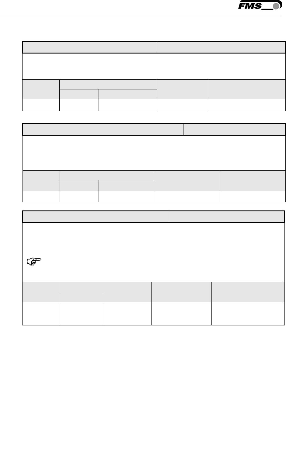
System Force LCD: Sys_F
Use: The System Force [Sys_F] determines the measuring capability of your
measuring roller. E.g. If two 500 N sensors are installed in your
measuring roller, enter 1000N. If only one 500N sensor is used, enter
500N. If sensors with sheaves are used (e.g. RMGZ-Series), the
nominal force 500N must be entered.
If the Device Mode Volt Gauge is set, this parameter is deactivated
Unit Parameter Range Selection Default
Min Max
N, kN, g,
kg, lb 1) 1 100’000 - 1000
1) The display shows the unit of measure that was previously selected
Force at max. Amplifier Output LCD: F@mOut
Use: This parameter defines what force value (N, kN, lb, g, kg) corresponds
to the maximum output of the amplifier (10V or 20mA).
If the Device Mode Volt Gauge is set, this parameter is deactivated
Unit Parameter Range Selection Default
Min Max
N, kN, g,
kg, lb 1) 1 100’000 - 1000
1) The display shows the unit of measure that was previously selected
Operating Manual EMGZ 310
10.01.2017 21
Offset Value LCD: Offset
Use: The offset value is used to compensate the roller weight (see chapter
3.4 “Offset Compensation”).
Unit Parameter Range Selection Default
Min Max
Digit -8000 +8000 - 0
Gain of Amplifier LCD: Gain
Use: This parameter stores the value determined with the Procedure
Calibration (see chapter 3.6). With a gain value ≥10.000, the display
format changes to 10.00.
Unit Parameter Range Selection Default
Min Max
- 0.001 20.000 - 1.000
Device Mode LCD: Mode
Use: The Device Mode determines the functionality of the amplifier. If Volt
Gauge is set, force values will be displayed only in Volt (V) or mA.
Force units won’t be available.
Each change of the Device Mode requires a re-calibration of the system
(see chapter 3.6).
Unit Parameter Range Selection Default
Min Max
- - - kgkNN
V kgkNN
Operating Manual EMGZ310 and EMGZ310.ComACT
10.01.2017 22
5 Configuration via FMS ComACTTM app
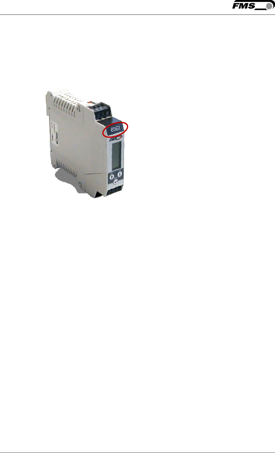
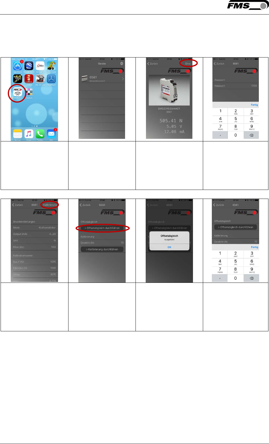
If you have purchased an EMGZ310.ComACT measuring amplifier you are able to
display actual readings and configure the amplifier via the FMS ComACTTM app.
You can identify the type of amp on the type label. The EMGZ310.ComACT has
also the last 4 digits of its serial number printed on the front housing.
Only a single mobile device at a time can connect to an amplifier.
As soon as the connection between amp and mobile device is setup, the display of
the amp will start flashing.
The FMS ComACTTM app is meant as an operation aid to display actual readings
and to help configure the amplifier. The settings are only stored in the amplifier
and not in the mobile device.
Operating Manual EMGZ 310
10.01.2017 23
5.1 Screenshots
Download FMS
ComACTTM app
Google Play Store
(Android); iTunes (IOS)
Overview with all
amplifiers within the
transmitting range.
Display of actual
readings with the
selected settings
(unit, gain, output,
etc.)
“Settings” requires a
password.
The password is
preset to “3231” and
it cannot be
modified.
„Calibration“ leads
you to the offset and
gain menu.
You can perform an
offset without any
further input. Make
sure that the web
does not material in
the
Successful input and
operations are
confirmed
Before you peform
the calibration, you
have to enter the
applied weight.
Operating Manual EMGZ310 and EMGZ310.ComACT
10.01.2017 24
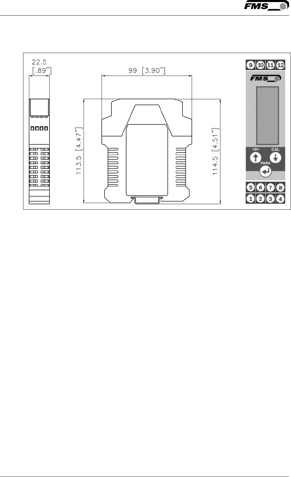
6 Dimensions
Fig. 8: Drawing EMGZ 310 rail mount housing E310004
Operating Manual EMGZ 310
10.01.2017 25
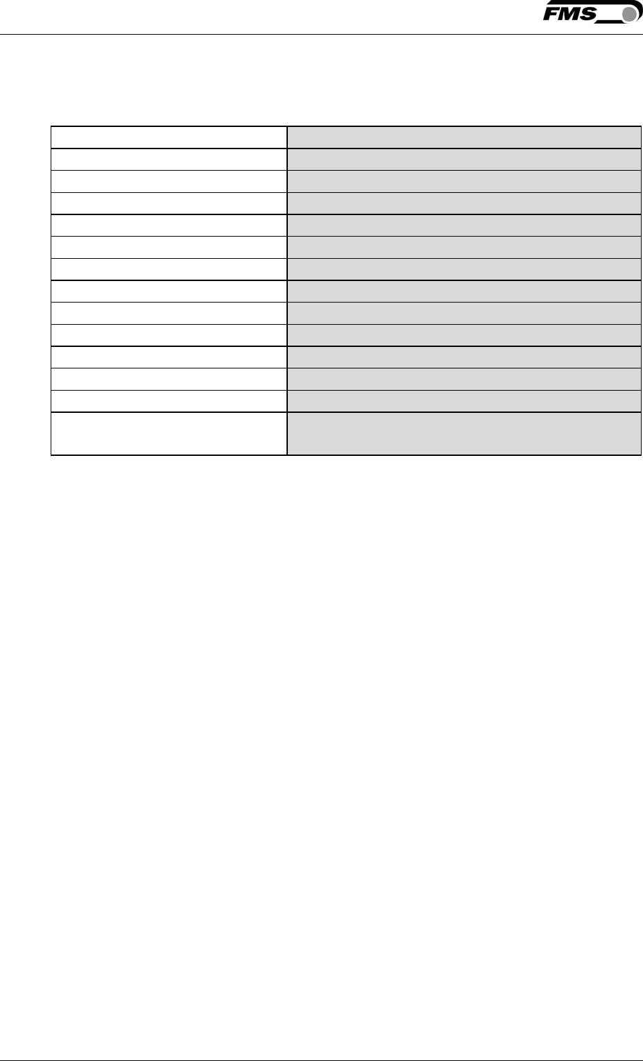
7 Technical Specification
Amplifier type Digital, microprocessor controlled
# of channel 1 channel for 2 sensors @ 350 Ω
Sensor excitation 5VDC max. 30mA (high voltage stability)
Linearity error < 0.1%
Processor cycle time 1ms
Operation / parameter setting 3 keys, 4-digit LCD display (alpha-num)
Resolution A/D converter ±8192 digit (14 bit)
Volt output ± 10V min. 1.0 kΩ (12 bit)
Current output 0/4...20mA max. 500 Ω (12 bit)
Power supply 24VDC (18...36VDC); max. 0.2A
Power consumption < 3.0W
Temperature range 0...+50°C [32...122°F]
Protection class IP20
Special functions Buttons for calibration and offset
compensation

Operating Manual EMGZ310 and EMGZ310.ComACT
10.01.2017 26
8 Your Settings
Parameter Your Settings Remarks
Output Current output
Filter Noise filter
Unit System unit
Sys_F System force of the roller
F@mOut Force at max. output
Offset Roller weight
Gain Amplification
Mode Requires new calibration

Operating Manual EMGZ 310
10.01.2017 27
9 Notes
Operating Manual EMGZ310 and EMGZ310.ComACT
10.01.2017 28
FMS Force Measuring Systems AG
Aspstrasse 6
8154 Oberglatt (Switzerland)
Tel. +41 44 852 80 80
Fax +41 44 850 60 06
info@fms-technology.com
www.fms-technology.com
FMS Italy
Via Baranzate 67
I-20026 Novate Milanese
Tel: +39 02 39487035
Fax: +39 02 39487035
fmsit@fms-
technology.com
FMS USA, Inc.
2155 Stonington Ave. Suite 119
Hoffman Estates, IL 60169 USA
Tel. +1 847 519 4400
Fax +1 847 519 4401
fmsusa@fms-technology.com
FMS UK
Highfield, Atch Lench Road
Church Lench
Evesham WR11 4UG, Great Britain
Tel. +44 1386 871023
Fax +44 1386 871021
fmsuk@fms-technology.com