FRIEDRICH Air Conditioner Room (42) Manual L0608153
User Manual: FRIEDRICH FRIEDRICH Air Conditioner Room (42) Manual FRIEDRICH Air Conditioner Room (42) Owner's Manual, FRIEDRICH Air Conditioner Room (42) installation guides
Open the PDF directly: View PDF ![]() .
.
Page Count: 21
J_' m Jl' m II'
Installation & Operation Guide
_%
Thru-the-Wall Series
115 Volts •UE08
230 Volts oUE10 oUE12
Model information can be found on the name plate on the front of the unit.
To register your application, complete and mail the enclosed registration card, or
register on-line at www.friedrich.com (USA only).
For your future convenience, record the model information here.
MODEL NUMBER SERIAL NUMBER PURCHASE DATE
920-136-01 (01/05)
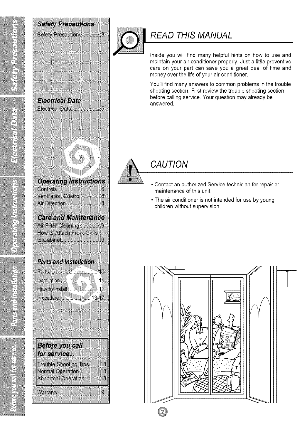
READ THIS MANUAL
Inside you will find many helpful hints on how to use and
maintain your air conditioner properly. Just a little preventive
care on your part can save you a great deal of time and
money over the life of your air conditioner.
You'll find many answers to common problems in the trouble
shooting section. First review the trouble shooting section
before calling service. Your question may already be
answered.
CAUTION
• Contact an authorized Service technician for repair or
maintenance of this unit.
• The air conditioner is not intended for use by young
children without supervision.
m__
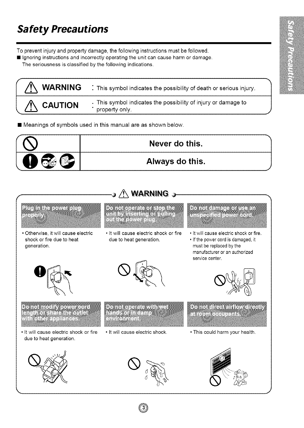
Safety Precautions
To prevent injury and property damage, the following instructions must be followed.
• Ignoring instructions and incorrectly operating the unit can cause harm or damage.
The seriousness is classified by the following indications.
,/_ WARNING "This symbol indicates the possibility of death or serious injury. /
J
//_ CAUTION .This symbol indicates the possibility of injury or damage to
•property only.
• Meanings of symbols used in this manual are as shown below.
I everOot s1
• Otherwise, it will cause electric
shock or fire due to heat
generation.
• It will cause electric shock or fire
due to heat generation.
• It will cause electric shock or fire
due to heat generation.
• It will cause electric shock.
• It will cause electric shock or fire.
• If the power cord is damaged, it
must be replaced by the
manufacturer or an authorized
service center.
• This could harm your health.
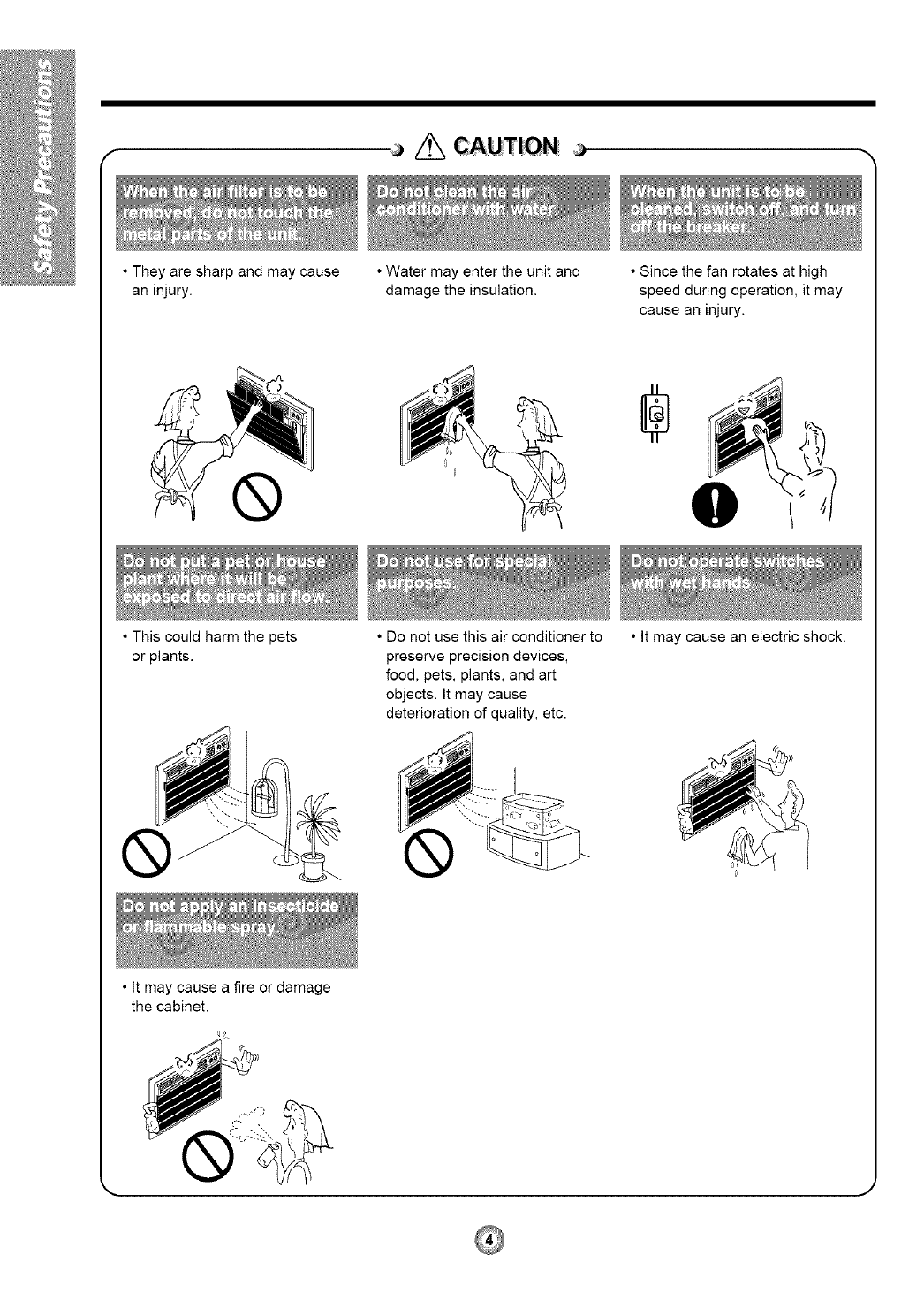
• They are sharp and may cause
an injury.
• Water may enter the unit and
damage the insulation.
• Since the fan rotates at high
speed during operation, it may
cause an injury.
• This could harm the pets
or plants.
• It may cause a fire or damage
the cabinet.
• Do not use this air conditioner to
preserve precision devices,
food, pets, plants, and art
objects. It may cause
deterioration of quality, etc.
• It may cause an electric shock.
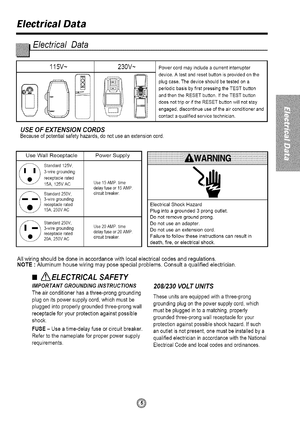
Electrical Data
Electrical Data
115V~
QT
qo
230V ~ Power cord may include a current interrupter
device. A test and reset button is provided on the
plug case. The device should be tested on a
periodic basis by first pressing the TEST button
and then the RESET button. If the TEST button
does not trip or if the RESET button wilI not stay
engaged, discontinue use of the air conditioner and
contact a qualified service technician.
USE OF EXTENSION CORDS
Becauseof potentialsafetyhazards,do not usean extensioncord.
Use Wall Receptacle Power Supply
Standard 125V,
3-wire grounding
receptacle rated
15A, 125V AC
Standard 250V,
3-wire grounding
receptacle rated
15A, 250V AC
Standa_ 250V,
3-wire grounding
receptacle rated
2gA, 250V AC
Use 15 AMP. time
delay fuse or 15 AMP
circuit breaker
Use 20 AMP. time
delay fuse or 20 AMP
circuit breaker
Electrical Shock Hazard
Plug into a grounded 3 prong outlet.
Do not remove ground prong.
Do not use an adapter.
Do not use an extension cord.
Failure to follow these instructions can result in
death, fire, or electrical shock.
All wiring should be done in accordance with local electrical codes and regulations.
NOTE : Aluminum house wiring may pose special problems. Consult a qualified electrician.
•/ ELECTRICAL SAFETY
IMPORTANT GROUNDING INSTRUCTIONS
The air conditioner has a three-prong grounding
plug on its power supply cord, which must be
plugged into properly grounded three-prong wall
receptacle for your protection against possible
shock.
FUSE - Use a time-delay fuse or circuit breaker.
Refer to the nameplate for proper power supply
requirements.
208/230 VOLT UNITS
These units are equippedwith a three-prong
grounding plugon the power supplycord, which
must be pluggedin to a matching,properly
groundedthree-prongwall receptaclefor your
protection againstpossibleshock hazard.If such
an outlet is not present, one must be installed by a
qualified electrician in accordancewith the National
Electrical Code and local codes and ordinances.
Operating Instructions
The controls will look like one of the following:
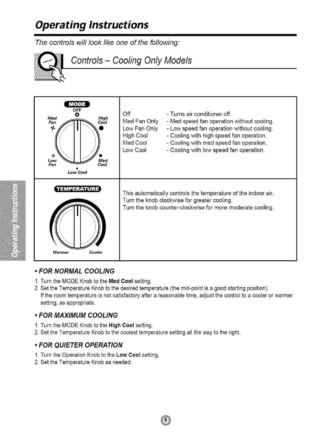
Controls- Cooling Only Models
Fan
OFF
0
Cool
Lo_Cool
|_ ivtI '-] ::1:!:_1 |lJ ;;
Warmer Cooler
Off
Med Fan Only
Low Fan Only
High Cool
Med Cool
Low Cool
- Turns air conditioner off.
- Med speed fan operation without cooling.
- Low speed fan operation without cooling.
- Cooling with high speed fan operation.
- Cooling with med speed fan operation.
- Cooling with low speed fan operation.
This automatically controls the temperature of the indoor air.
Turn the knob clockwise for greater cooling.
Turn the knob counter-clockwise for more moderate cooling.
•FOR NORMAL COOLING
1. Turn the MODE Knob to the Med Cool setting.
2. Set the Temperature Knob to the desired temperature (the mid-point is a good starting position).
If the room temperature is not satisfactory after a reasonable time, adjust the control to a cooler or warmer
setting, as appropriate.
•FOR MAXIMUM COOLING
1. Turn the MODE Knob to the High Cool setting.
2. Set the Temperature Knob to the coolest temperature setting all the way to the right.
•FOR QUIETER OPERATION
1. Turn the Operation Knob to the Low Cool setting.
2. Set the Temperature Knob as needed.
The controls will look like one of the following:
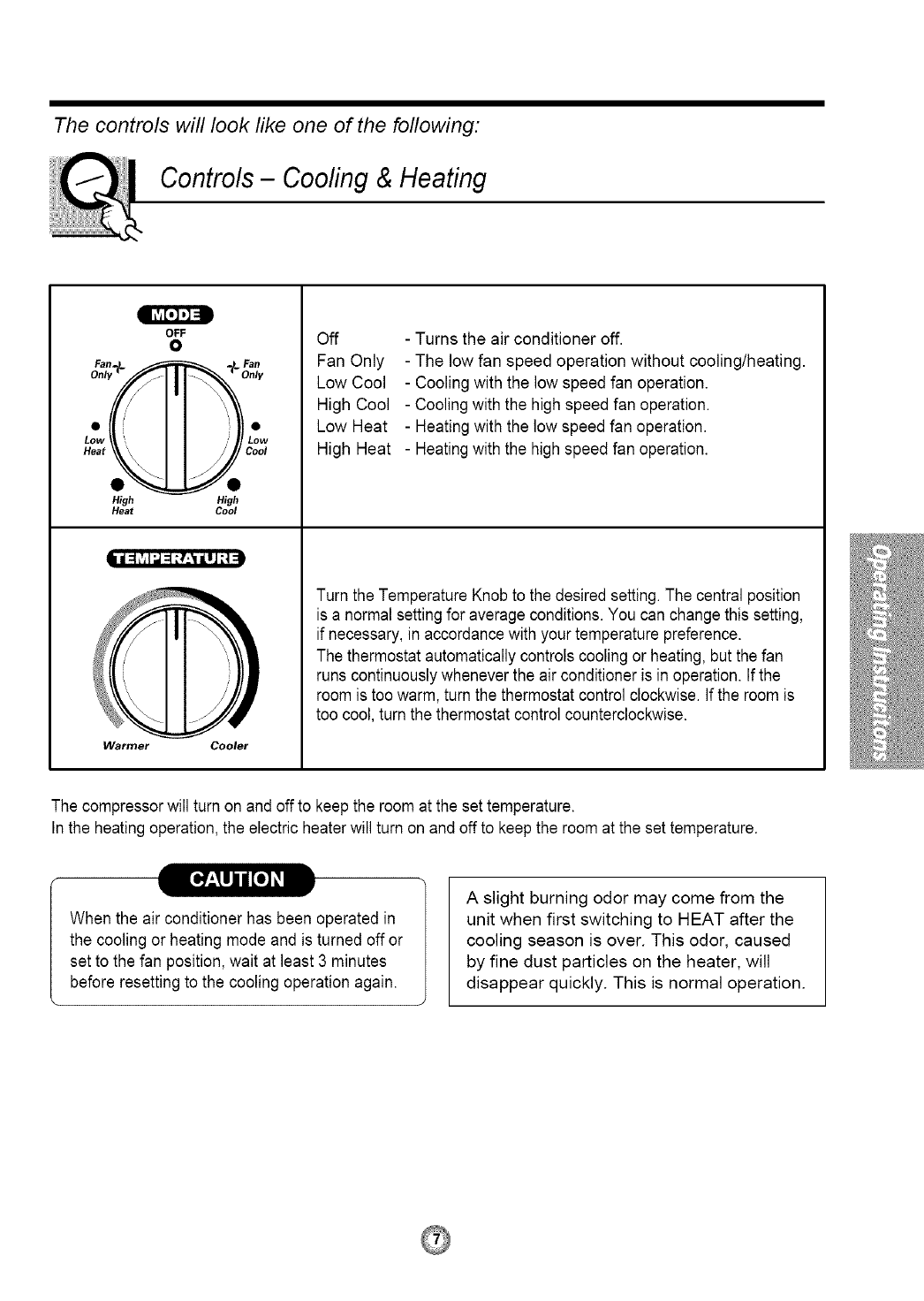
Controls- Cooling & Heating
OFF
0
High High
Heat Cool
i =1,';1;.1=_5E,'_iJ] _1
Warmer Cooler
Off
Fan Only
Low Cool
High Cool
Low Heat
High Heat
- Turns the air conditioner off.
- The low fan speed operation without cooling/heating.
- Cooling with the low speed fan operation.
- Cooling with the high speed fan operation.
- Heating with the low speed fan operation.
- Heatingwith the highspeed fan operation.
Turn the Temperature Knob to the desired setting.The central position
is a normal setting for average conditions.You can change this setting,
if necessary, in accordance with your temperature preference.
The thermostat automaticallycontrols cooling or heating, but the fan
runs continuouslywhenever the air conditioner is in operation. Ifthe
room is too warm, turn the thermostat controlclockwise. If the room is
too cool,turn the thermostat control counterclockwise.
The compressorwill turn on and off to keepthe room at the set temperature.
In the heating operation, the electric heater will turn on and off to keep the room at the set temperature.
When the air conditioner has been operated in
the cooling or heating mode and is turned off or
set to the fan position, wait at least 3 minutes
before resetting to the cooling operation again.
A slight burning odor may come from the
unit when first switching to HEAT after the
cooling season is over. This odor, caused
by fine dust particles on the heater, will
disappear quickly. This is normal operation.
Additional controls and important information.
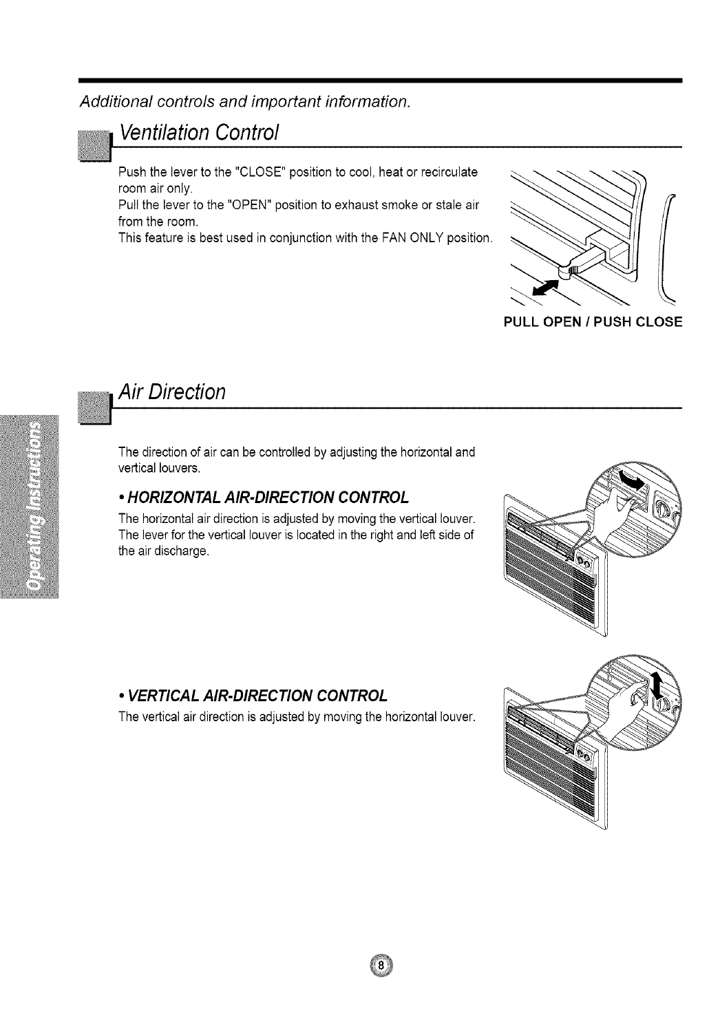
Ventilation Control
Push the lever to the "CLOSE" position to cool, heat or recirculate
room air only.
Pull the lever to the "OPEN" position to exhaust smoke or stale air
from the room.
This feature is best used in conjunction with the FAN ONLY position.
PULL OPEN/PUSH CLOSE
AirDirecfion
The directionof air can be controlledby adjustingthe horizontaland
vertical louvers.
•HORIZONTAL AIR-DIRECTION CONTROL
The horizontalair directionis adjusted by movingthe vertical louver.
The lever for the vertical louver is located inthe right and left side of
the air discharge.
• VERTICAL AIR-DIRECTION CONTROL
The vertical air directionis adjusted by movingthe horizontallouver.
Care and Maintenance
TURN THE AIR CONDITIONER OFF AND REMOVE THE PLUG FROM THE POWER OUTLET.
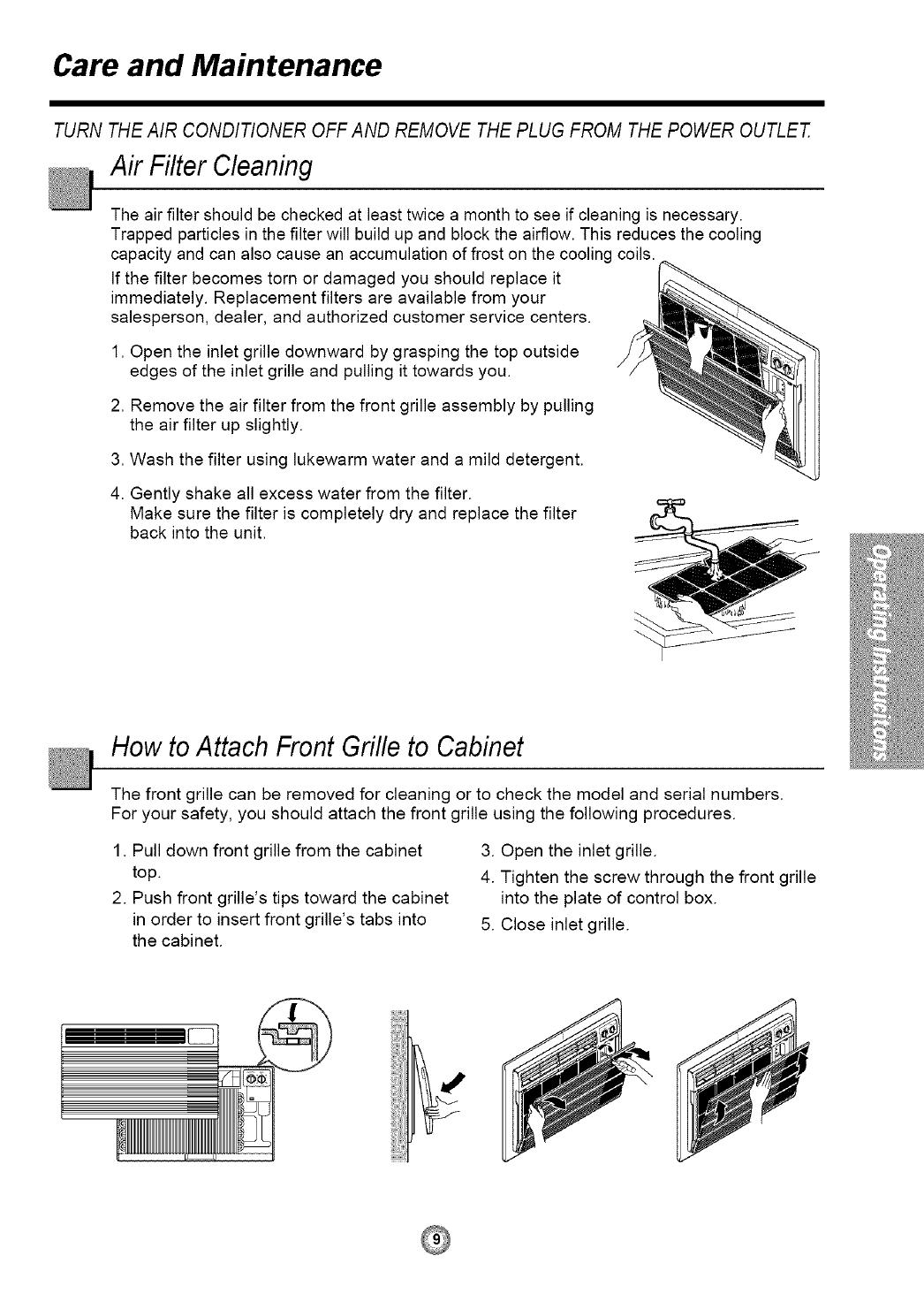
Air Filter Cleaning
The air filter should be checked at least twice a month to see if cleaning is necessary.
Trapped particles in the filter will build up and block the airflow. This reduces the cooling
capacity and can also cause an accumulation of frost on the cooling coils.
If the filter becomes torn or damaged you should replace it
immediately. Replacement filters are available from your
salesperson, dealer, and authorized customer service centers.
1. Open the inlet grille downward by grasping the top outside
edges of the inlet grille and pulling it towards you.
2. Remove the air filter from the front grille assembly by pulling
the air filter up slightly.
3. Wash the filter using lukewarm water and a mild detergent.
4. Gently shake all excess water from the filter.
Make sure the filter is completely dry and replace the filter
back into the unit,
How to Attach Front Grille to Cabinet
The front grille can be removed for cleaning or to check the model and serial numbers.
For your safety, you should attach the front grille using the following procedures.
1. Pull down front grille from the cabinet
top.
2. Push front grille's tips toward the cabinet
in order to insert front grille's tabs into
the cabinet.
3. Open the inlet grille.
4. Tighten the screw through the front grille
into the plate of control box.
5. Close inlet grille.
Parts
Learning part name prior to installation will help you understand the installation procedure.
Parts
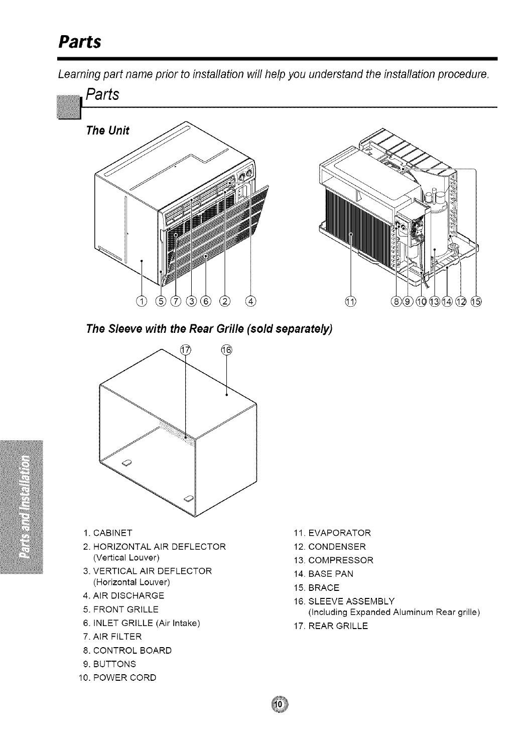
The Unit
The Sleeve with the Rear Grille (sold separately)
1. CABINET
2. HORIZONTAL AIR DEFLECTOR
(Vertical Louver)
3. VERTICAL AIR DEFLECTOR
(Horizontal Louver)
4. AIR DISCHARGE
5. FRONT GRILLE
6. INLET GRILLE (Air intake)
7. AIR FILTER
8. CONTROL BOARD
9. BUTTONS
10. POWER CORD
11. EVAPORATOR
12. CONDENSER
13. COMPRESSOR
14. BASE PAN
15. BRACE
16. SLEEVE ASSEMBLY
(including Expanded Aluminum Rear grille)
17. REAR GRILLE
Installation
Remove packing sheet from the back of the sleeve, and
packing corner and blue tape from the air conditioner.
INSTALLATION REQUIREMENTS
If you use an existing wall sleeve, you should measure
its dimensions.
Install the new air conditioner according to these
installation instructions to achieve the best performance.
All wall sleeves used to mount the new air conditioner
must be in good structural condition and have a rear grille
to securely attach the new air conditioner. (FIG. 1)
Installing the FRIEDRICH USC sleeve ensures optimal
performance of the new air conditioner. (FIG. 2)
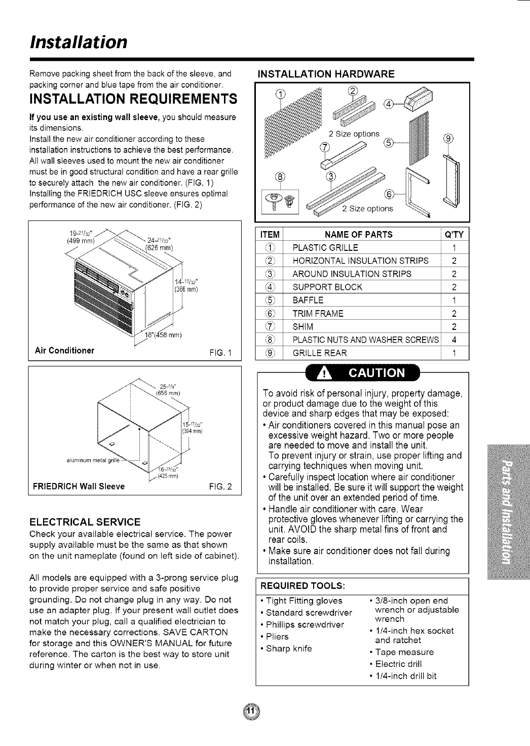
19-2//32"
(499 mm)
Air Conditioner
/3/32"
mm)
8"(458mr'n)
FIG. 1
INSTALLATION HARDWARE
s
2 Size options
ITEM NAME OF PARTS iQ'TY
_1_ PLASTIC GRILLE 1
HORIZONTAL INSULATION STRIPS 2
AROUND INSULATION STRIPS 2
(49 SUPPORT BLOCK 2
BAFFLE 1
_6_ TRIM FRAME 2
SHIM 2
_8_ PLASTIC NUTS AND WASHER SCREWS i 4
<9_ GRILLE REAR 1
25-7/s"
_{656 mm)
(394mm}
aluminum metal grill
FRIEDRICH Wall Sleeve FIG. 2
ELECTRICAL SERVICE
Check your available electrical service. The power
supply available must be the same as that shown
on the unit nameplate (found on left side of cabinet).
All models are equipped with a 3-prong service plug
to provide proper service and safe positive
grounding. Do not change plug in any way. Do not
use an adapter plug. If your present wall outlet does
not match your plug, call a qualified electrician to
make the necessary corrections. SAVE CARTON
for storage and this OWNER'S MANUAL for future
reference. The carton is the best way to store unit
during winter or when not in use.
To avoid risk of personal injury, property damage,
or product damage due to the weight of this
device and sharp edges that may be exposed:
• Air conditioners covered in this manual pose an
excessive weight hazard. Two or more people
are needed to move and install the unit.
To prevent injuryor strain, use proper lifting and
carrying techniques when moving unit.
• Carefully inspect location where air conditioner
will be installed. Be sure itwill supportthe weight
of the unit over an extended period of time.
• Handle air conditioner with care. Wear
protective gloves whenever lifting or carrying the
unit. AVOID the sharp metal fins of front and
rear coils.
• Make sure air conditioner does not fall during
installation.
REQUIRED TOOLS:
•Tight Fitting gloves
• Standard screwdriver
• Phillips screwdriver
• Pliers
• Sharp knife
•3/8-inch open end
wrench or adjustable
wrench
• 1/4-inch hex socket
and ratchet
• Tape measure
• Electric drill
• 1/4-inch drill bit
INSTALLATION
Installing the FRIEDRICHUSC sleeve ensures
optional performancesof the unit.
Ifyou decide to keep the existing wall sleeve, you
have to redirectthe louvers at the back of the wall
sleeve. Referto FIG. 8 on p14. The use of pliers is
recommended. Ifyou DO NOT redirect, you run
the risk of poor performance or premature product
failure. This is not covered under the terms of the
FRIEDRICHwarranty.
•Pick a location which will allow the conditioned air
to blow into the area you want. Good installation
with special attention to the proper position of the
unit will lessen the chance that service will be
needed.
ITEMS IN INSTALLATION HARDWARE
You may not need all parts in the kit. Discard
unused parts
ITEM DIMENSIONS(inches)Qty.
Plastic grille
Horizontal Insulation Strips
Around Insulation Strips
263/4 x 161/2
13/8 x 5/8 x 273/18
13/8 x 13/8 x 273/16
13/8 x 3/4 x 611/2
13/8 x 13/8 x 611/2
13/4 x 13/8 x 45/18
14 x 41/2 x 1/8
13x 1 x3/4
1
1
1
1
1
2
1
2
2
4
4
1
Support Block
Baffle
Shim
Trim Frame
Washer Screw
Nuts(Plastic)
Grille Rear
HOW TO INSTALL
_1 Before installing the unit, identify the existing
wall sleeve from the list below.
Wall Sleeve Dimensions (inches)
Brand Width Height
White-Westinghouse
Frigidaire 25-1/2 15-1/4
Carrier (52F series)
General Electric 26 15-5/8
/Hotpoint
Whirlpool 25-7/8 16-1/2
Fedders/Emerson 27 16-3/4
Friedrich WSC
FRIEDRICH USC 25-7/8 15-17t32
Emerson/Fedders 26-3/4 15-3/4
Carrier (51S Series) 25-314 16-7/8
Depth
16, 17-1/2
or 22
16-7/8
17-1/8
or 23
16-3/4
or 19-3/4
16-23t32
15
18-5/8
NOTE: All wall sleeves used to mount the new Air
Conditioner must be in sound structural condition
and have a rear grille that securely attaches to
sleeve, or rear flange that serves as a stop for the
Air Conditioner.
_'_ Remove old air conditioner from existing wall
sleeve.
_J Clean the interior of an existing sleeve.
(Do not disturb seals or gaskets.)
L_Wall sleeve must be securely fastened in wall
before installing the air conditioner. Use the
nails or screws through sleeve into wall, if
needed. Repaint sleeve if needed.
I_J Prepare the wall sleeve for installation of the unit.
If you plan to use your existing wall sleeve, and it
is not FRIEDRICH, use procedure B or C below.
Procedure Brand Depth(inches',
A(page 13) FRIEDRICH USC 16-23/32
White-Westinghouse 16, 17-1/2
Frigidaire Carrier or 22
B (52F series)
General Electric
(pages 14~15', 16-7/8
/Hotpoint
Whirlpool 17-1/8 or 23
Carrier (51S series) 18-5/8
FedderslEmerson 16-3/4
CFriedrich WSC or 19-3/4
(pages 16~17', Emerson/Fedders 15
D Install new unit into wall sleeve.
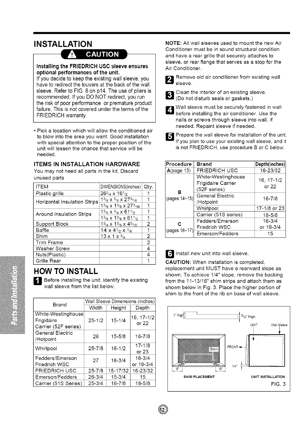
CAUTION: When installation is completed,
replacement unit MUST have arearward slope as
shown. To achieve 1/4" slope, remove the backing
from the 11-13/16" shim strips and attach them as
shown below in Fig. 3. Place the higher portion of
shim to the front of the rib on base of wall sleeve.
1" highI [
SHIM PLACEMENT
lI 3/4" High
UNIT Wall Sleeve
UNIT INSTALLATION
FIG. 3
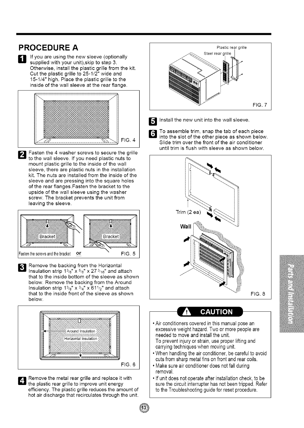
PROCEDURE A
If you are using the new sleeve (optionally
supplied with your unit),skip to step 3.
Otherwise, install the plastic grille from the kit.
Cut the plastic grille to 25-112" wide and
15-114" high. Place the plastic grille to the
inside of the wall sleeve at the rear flange.
FIG. 4
_'_ Fasten the 4 washer screws to secure the grille
to the wall sleeve. If you need plastic nuts to
mount plastic grille to the inside of the wall
sleeve, there are plastic nuts in the installation
kit. The nuts are installed from the inside of the
sleeve and are pressing into the square holes
of the rear flanges.Fasten the bracket to the
upside of the wall sleeve using the washer
screw. The bracket prevents the unit from
leaving the sleeve.
Fastenthescrewsandthebracket or FIG. 5
_J Remove the backing from the Horizontal
Insulation strip 13/8" x 5/8" x 273/16" and attach
that to the inside bottom of the sleeve as shown
below. Remove the backing from the Around
Insulation strip 13/8" X3/4" X 611/2" and attach
that to the inside front of the sleeve as shown
below.
Ptastic rear grille
SteeI rear (
FIG. 7
E_4J Install the new unit into the wall sleeve.
Q To assemble trim, snap the tab of each piece
into the slot of the other piece as shown below.
Slide trim over the front of the air conditioner
until trim is flush with sleeve as shown below.
Trim (2 ea)
Wall
"I
FIG. 8
_!'_ [_f_,_l]lI [el _1
FIG. 6
Q Remove the metal rear grille and replace it with
the plastic rear grille to improve unit energy
efficiency. The plastic grille reduces the amount of
hot air discharge that recirculates through the unit.
•Air conditionerscoveredinthismanualposean
excessiveweighthazard.Twoormorepeopleare
neededto moveandinstallthe unit.
To preventinjuryor strain,useproperliftingand
carryingtechniqueswhenmovingunit.
•Whenhandlingtheair conditioner,becarefulto avoid
cutsfromsharpmetalfinson frontandrearcoils.
• Makesureairconditionerdoesnotfallduring
removal.
• If unitdoesnotoperateafterinstallationcheck,to be
surethe circuitinterrupterhasnot beentripped.Refer
to theTroubleshootingguidefor resetprocedure.
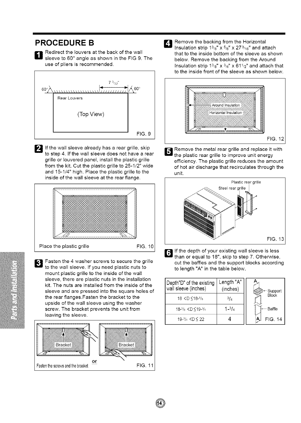
PROCEDURE B
Eli Redirect the louvers at the back of the wall
sleeve to 60 ° angle as shown in the FIG 9. The
use of pliers is recommended.
73'32
\\\\\\\\\\\\\\\\\\\l_//lllll/ll
Rear Louvers
(Top View)
_&6_0°
FIG. 9
I_lf the wall sleeve already has a rear grille, skip
to step 4. If the wall sleeve does not have a rear
grille or Iouvered panel, install the plastic grille
from the kit. Cut the plastic grille to 25-1/2" wide
and 15-1/4" high. Place the plastic grille to the
inside of the wall sleeve at the rear flange.
Place the plastic grille FIG. 10
_J Fasten the 4 washer screws to secure the grille
to the wall sleeve. If you need plastic nuts to
mount plastic grille to the inside of the wall
sleeve, there are plastic nuts in the installation
kit. The nuts are installed from the inside of the
sleeve and are pressed into the square holes of
the rear flanges.Fasten the bracket to the
upside of the wall sleeve using the washer
screw. The bracket prevents the unit from
leaving the sleeve.
D Remove the backing from the Horizontal
Insulation strip 13/8'' x 5/e" x 273/16" and attach
that to the inside bottom of the sleeve as shown
below. Remove the backing from the Around
Insulation strip 13/8" X3/4" X 611/2'' and attach that
to the inside front of the sleeve as shown below.
FIG. 12
_ Remove the metal rear grille and replace it with
the plastic rear grille to improve unit energy
efficiency. The plastic grille reduces the amount
of hot air discharge that recirculates through the
unit.
PIastic rear grille
Steet rear c
FIG. 13
Q If the depth of your existing wall sleeve is less
than or equal to 18", skip to step 7. Otherwise,
cut the baffles and the support blocks according
to length "A" in the table below.
Depth"D"ofthe existing
wallsleeve(inches)
18 <D _<18-5/8
18-5/B<D _<19-3/4
19-3/4<D_<22
Length"A"
(inches)
3/4
1-3/4
4
_ upport
Block
•_]'_ Baffle
A/ FIG. 14
or
Fastenthescrewsandthebracket FIG. 1
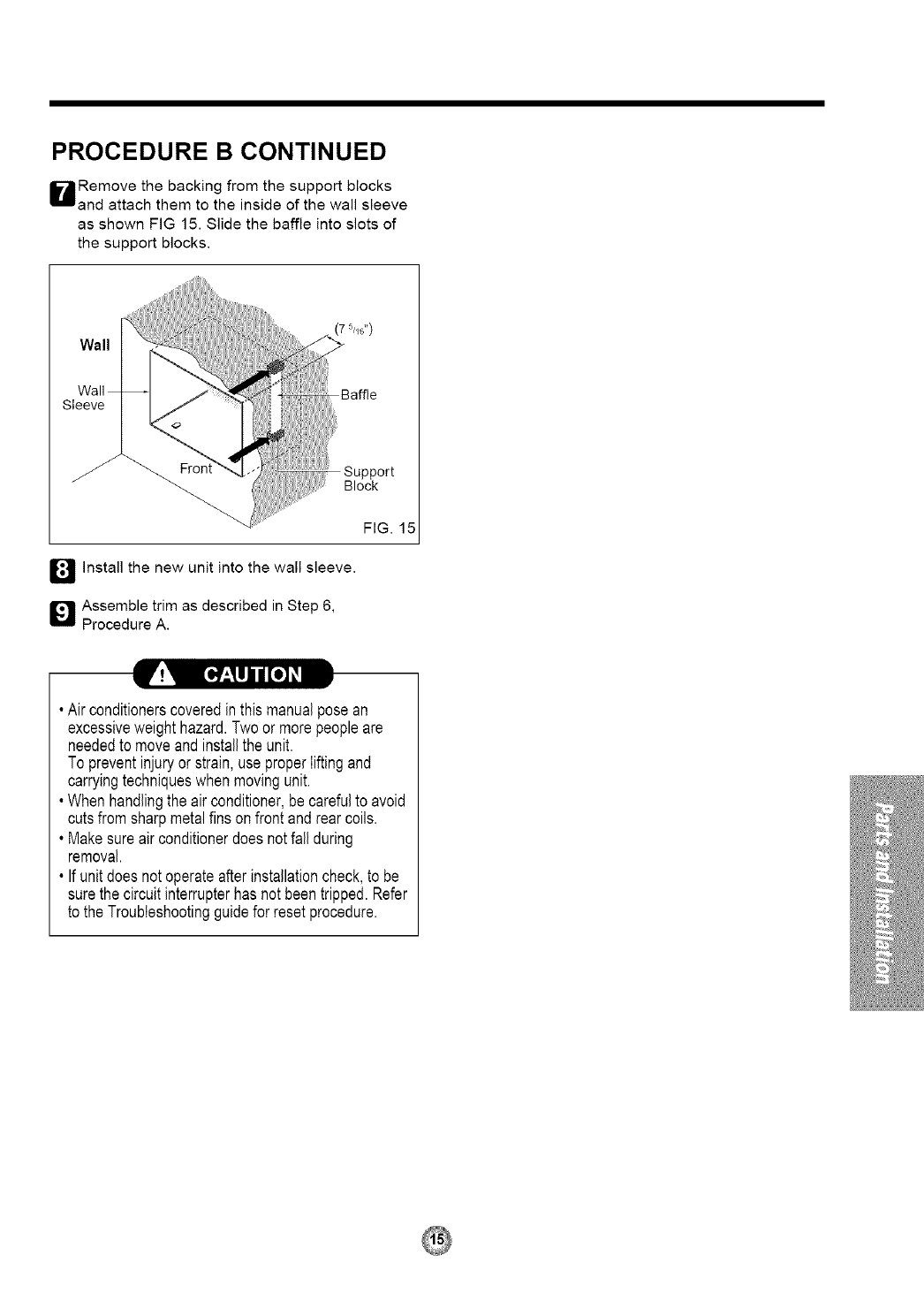
PROCEDURE B CONTINUED
HRemove the backing from the support blocks
and attach them to the inside of the wall sleeve
as shown FIG 15. Slide the baffle into slots of
the support blocks.
_/all
Vail
we
Front
(7 5//6'*)
Block
_1_ Install the new unit into the wall sleeve.
Q Assemble trim as described in Step 6,
Procedure A.
FIG. 15
• Airconditionerscoveredinthis manualposean
excessiveweighthazard.Twoor morepeopleare
neededto moveandinstallthe unit.
To preventinjuryorstrain,useproperliftingand
carryingtechniqueswhenmovingunit.
• Whenhandlingthe air conditioner,be carefulto avoid
cutsfromsharpmetalfinsonfrontandrearcoils.
• Makesureairconditionerdoesnotfall during
removal.
• Ifunitdoesnotoperateafterinstallationcheck,to be
surethecircuitinterrupterhas notbeentripped.Refer
to the Troubleshootingguidefor resetprocedure.
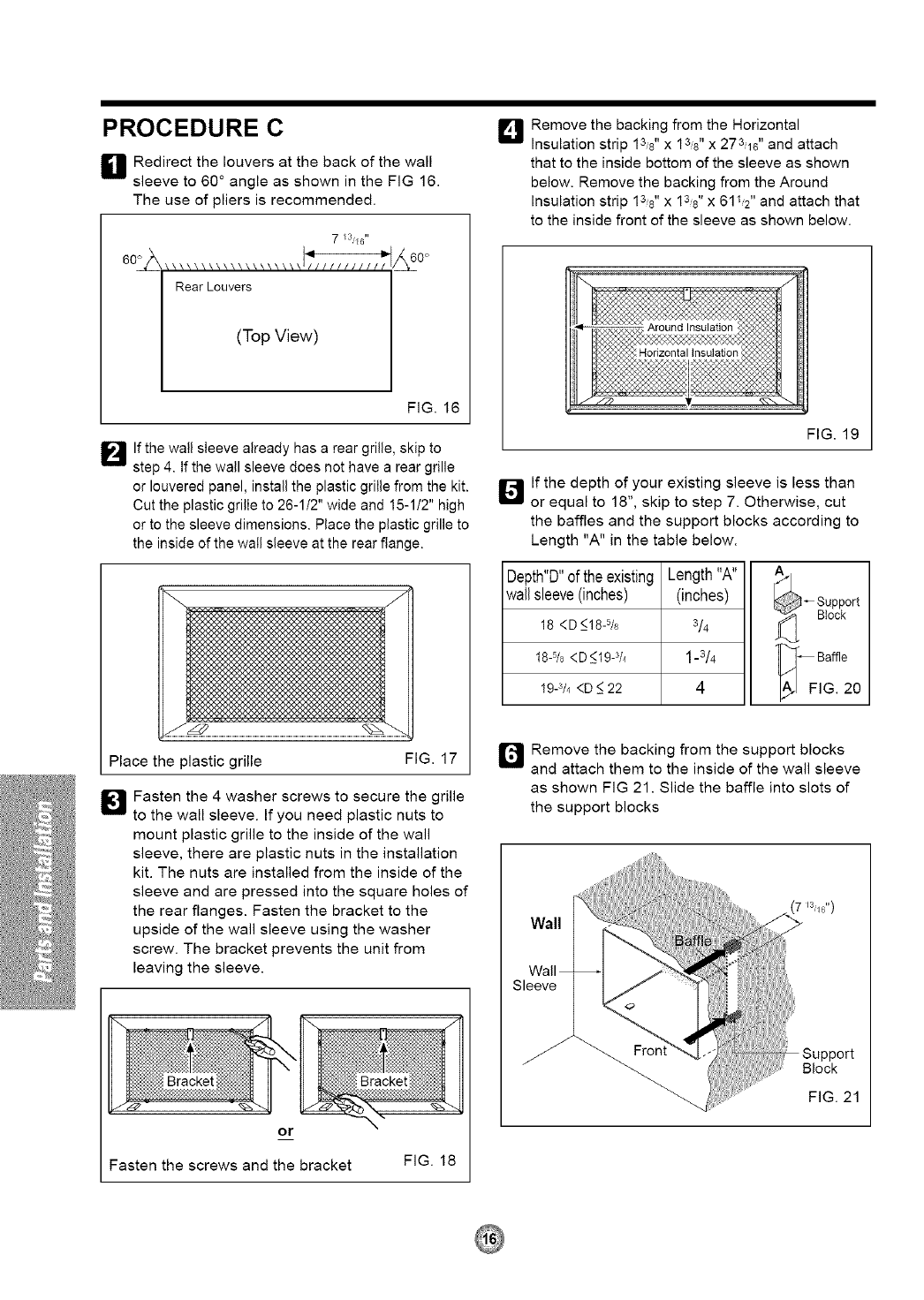
PROCEDURE C
Eli Redirect the louvers at the back of the wall
sleeve to 60 ° angle as shown in the FIG 16.
The use of pliers is recommended.
7 [3'E6"
602
Rear Louvers
(Top View)
FIG. 16
I_11 If the watl sleeve already has a rear grille, skip to
step 4. If the wall sleeve does not have a rear grille
or Iouvered panel, install the plastic grille from the kit.
Cut the plastic grille to 26-1/2" wide and 15-112" high
or to the sleeve dimensions. Place the plastic grille to
the inside of the wall sleeve at the rear flange.
Place the plastic grille FIG. 17
[]Fasten the 4 washer screws to secure the grille
to the wall sleeve. If you need plastic nuts to
mount plastic grille to the inside of the wall
sleeve, there are plastic nuts in the installation
kit. The nuts are installed from the inside of the
sleeve and are pressed into the square holes of
the rear flanges. Fasten the bracket to the
upside of the wall sleeve using the washer
screw. The bracket prevents the unit from
leaving the sleeve.
or
Q Remove the backing from the Horizontal
Insulation strip 13,8" x 138" x 273,16" and attach
that to the inside bottom of the sleeve as shown
below. Remove the backing from the Around
Insulation strip 138" x 138" x 6112" and attach that
to the inside front of the sleeve as shown below.
FIG. 19
[] If the depth of your existing sleeve is less than
or equal to 18", skip to step 7. Otherwise, cut
the baffles and the support blocks according to
Length "A" in the table below.
Depth"D"of theexisting
wallsleeve(inches)
18 <D _<18-5/8
18-5/B< D_<19-3/4
19-3/4<D_<22
Length"A"
(inches)
3/4
1-3/4
4
_;_-- Support
Block
•_-- Baffle
A_ FIG. 20
I_ Remove the backing from the support blocks
and attach them to the inside of the wall sleeve
as shown FIG 21. Slide the baffle into slots of
the support blocks
Vail
Call
we
Fasten the screws and the bracket FIG. 18
PROCEDURE C CONTINUED
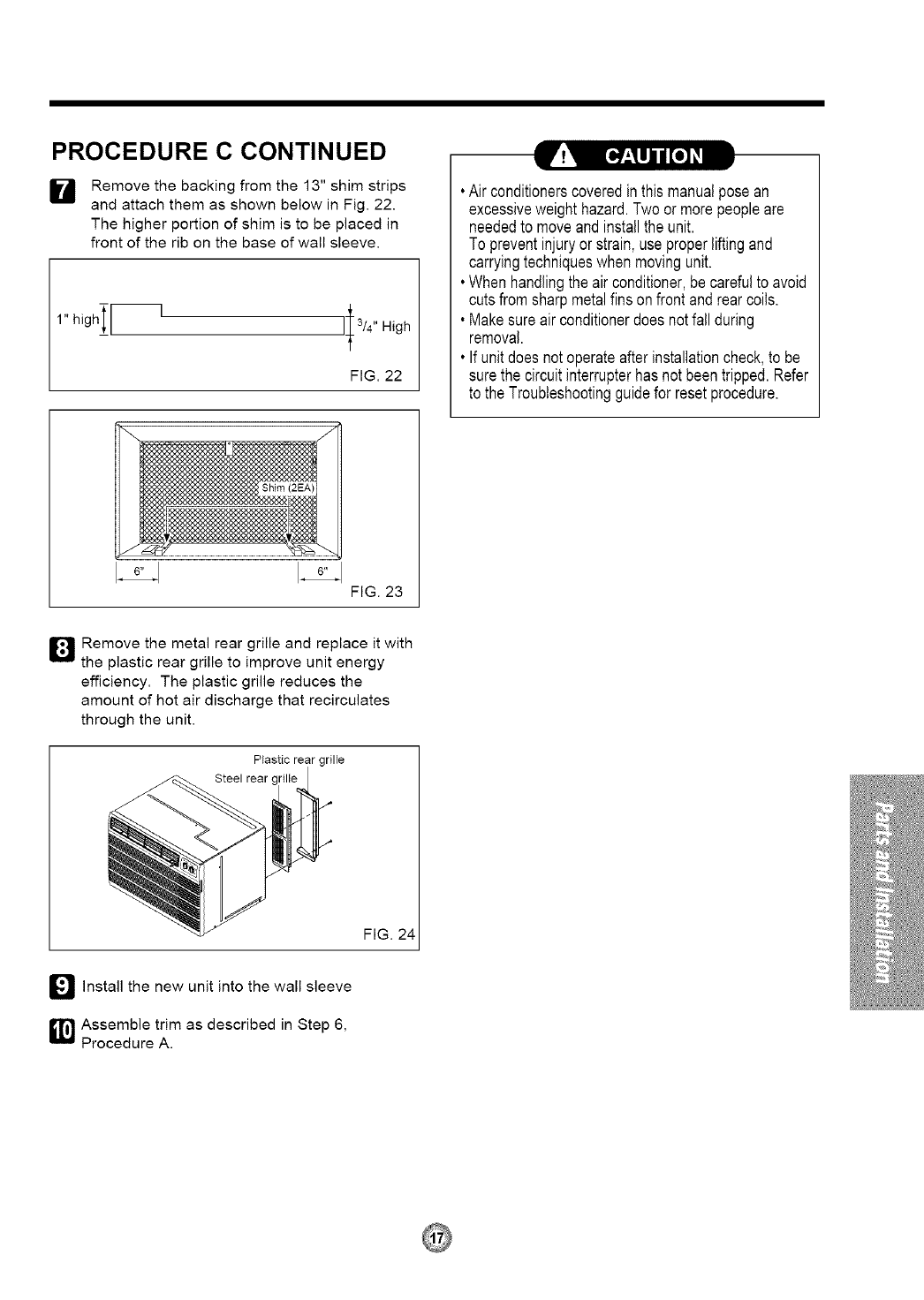
H Remove the backing from the 13" shim strips
and attach them as shown below in Fig. 22.
The higher portion of shim is to be placed in
front of the rib on the base of wall sleeve.
FIG. 22
• Airconditionerscoveredinthismanualposean
excessiveweighthazard.Twoormorepeopleare
neededto moveandinstallthe unit.
To preventinjuryorstrain,useproperliftingand
carryingtechniqueswhen movingunit.
• Whenhandlingthe air conditioner,becarefulto avoid
cutsfromsharpmetalfinsonfrontandrearcoils.
• Makesureair conditionerdoes notfall during
removal.
• Ifunitdoesnot operateafterinstallationcheck,to be
surethe circuitinterrupterhasnotbeentripped.Refer
to the Troubleshootingguidefor resetprocedure.
FIG. 23
D Remove the metal rear grille and replace it with
the plastic rear grille to improve unit energy
efficiency. The plastic grille reduces the
amount of hot air discharge that recirculates
through the unit.
Plastic rear grille
Steel rear
FIG. 24
_ Install the unit into the wall sleeve
new
_1_ Assemble trim as described in Step 6,
Procedure A.
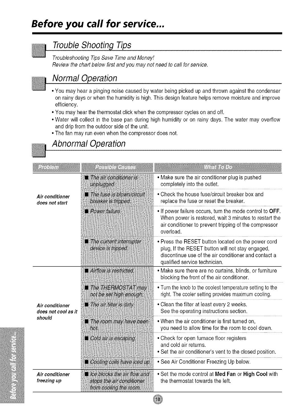
Before you call for service...
Trouble Shooting Tips
Troubleshooting Tips Save Time and Money!
Review the chart below first and you may not need to call for service.
Normal Operation
• You may hear a pinging noise caused by water being picked up and thrown against the condenser
on rainy clays or when the humidity is high. This design feature helps remove moisture and improve
efficiency.
• You may hear the thermostat click when the compressor cycles on and off.
• Water will collect in the base pan during high humidity or on rainy days. The water may overflow
and drip from the outdoor side of the unit.
• Thefan may run even when the compressor does not.
Abnormal Operation
• Make sure the air conditioner plug is pushed
completely into the outlet.
Air conditioner •Check the house fuse/circuit breaker box and
does not start replace the fuse or reset the breaker.
• If powerfailure occurs, turn the mode control to OFF.
When power is restored, wait 3 minutes to restart the
air conditioner to prevent tripping of the compressor
overload.
Air conditioner
does not cool as it
should
Air conditioner
freezing up
ttlO_{
_001_
• Press the RESET button located on the powercord
plug, If the RESET button will not stay engaged,
discontinue use of the air conditioner and contact a
qualified service technician.
• Make sure there are no curtains, blinds, or furniture
blocking the front of the air conditioner.
• Turn the knobto the coolesttemperaturesettingto the
right.The cooler settingprovidesmaximumcooling.
• Clean the filter at least every 2 weeks.
See the operating instructions section.
• When the air conditioner is first turned on,
you need to allow time for the room to cool down.
• Check for open furnace floor registers
and cold air returns.
• Set the air conditioner's vent to the closed position.
• See Air Conditioner Freezing Up below.
• Set the mode control at Med Fan or High Cool with
the thermostat towards the left.
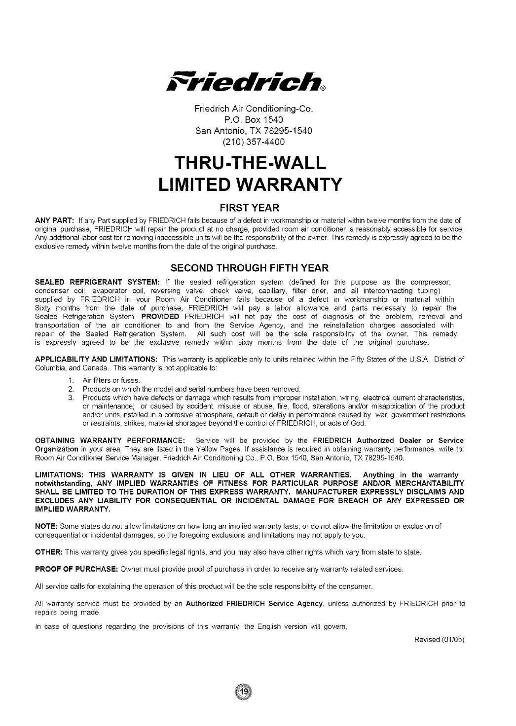
Friedrich Air Conditioning-Co.
P.O. Box 1540
San Antonio, TX 78295-1540
(210) 357-4400
THRU-THE-WALL
LIMITED WARRANTY
FIRST YEAR
ANY PART: If any Part supplied by FRIEDRtCH fails because of a defect in workmanship or material within twelve months from the date of
original purchase, FRIEDRICH wil! repair the product at no charge, provided room air conditioner is reasonably accessible for service.
Any additional labor cost for removing inaccessible units will be the responsibility of the owner. This remedy is expressly agreed to be the
exclusive remedy within twelve months from the date of the orJginat purchase.
SECOND THROUGH FIFTH YEAR
SEALED REFRIGERANT SYSTEM: If the sealed refrigeration system (defined for this purpose as the compressor,
condenser coil, evaporator coil, reversing valve, check valve, capillary, filter drier, and al! interconnecting tubing)
supplied by FRIEDRICH in your Room Air Conditioner fails because of a defect in workmanship or material within
Sixty months from the date of purchase, FRIEDRICH will pay a labor allowance and parts necessary to repair the
Sealed Refrigeration System; PROVIDED FRIEDRICH will not pay the cost of diagnosis of the problem, removal and
transportation of the air conditioner to and from the Service Agency, and the reinstallation charges associated with
repair of the Sealed Refrigeration System. All such cost will be the sole responsibility of the owner. This remedy
is expressly agreed to be the exclusive remedy within sixty months from the date of the original purchase.
APPLICABILITY AND LIMITATIONS: This warranty is applicable only to units retained within the Fifty States of the US.A. District of
Columbia, and Canada. This warranty is not applicable to:
1. Air filters or fuses.
2. Products on which the model and serial numbers have been removed.
3. Products which have defects or damage which results from improper installation, wiring, electrical current characteristics,
or maintenance; or caused by accident, misuse or abuse, fire, flood, alterations and/or misapplication of the product
and/or units installed in a corrosive atmosphere, default or delay in performance caused by war, government restrictions
or restraints, strikes, material shortages beyond the control of FRIEDRICH, or acts of God.
OBTAINING WARRANTY PERFORMANCE: Service will be provided by the FRIEDRICH Authorized Dealer or Service
Organization in your area. They are tisted in the Yellow Pages. If assistance is required in obtaining warranty performance, write to:
Room Air Conditioner Service Manager, Friedrich Air Conditioning Co., P.O. Box 1540, San Antonio, TX 78285-1540.
LIMITATIONS: THIS WARRANTY IS GIVEN IN LIEU OF ALL OTHER WARRANTIES. Anything in the warranty
notwithstanding, ANY IMPLIED WARRANTIES OF FITNESS FOR PARTICULAR PURPOSE AND/OR MERCHANTABILITY
SHALL BE LIMITED TO THE DURATION OF THIS EXPRESS WARRANTY. MANUFACTURER EXPRESSLY DISCLAIMS AND
EXCLUDES ANY LIABILITY FOR CONSEQUENTIAL OR INCIDENTAL DAMAGE FOR BREACH OF ANY EXPRESSED OR
IMPLIED WARRANTY.
NOTE: Some states do not allow limitations on how long an implied warranty lasts, or do not allow the limitation or exclusion of
consequential or incidental damages, so the foregoing exclusions and limitations may not apply to you.
OTHER: This warranty gives you specific legal rights, and you may also have other rights which vary from state to state.
PROOF OF PURCHASE: Owner must provide proof of purchase in order to receive any warranty related services.
All service calls for explaining the operation of this product will be the sole responsibility of the consumer.
AII warranty service must be provided by an Authorized FRIEDRICH Service Agency, unless authorized by FRtEDRtCH prior to
repairs being made.
tn case of questions regarding the provisions of this warranty, the English version will govern.
Revised (01/05)

Memo
FRIEDRICH AIR CONDITIONING CO. INC.
PO Box 1540 • San Antonio, Texas 78295-1540
4200 N. Pan Am Expressway • San Antonio, Texas 78218-5212
(210) 357-4400 ° FAX (210)357-4490
Visitenos en Internet: www.friedrich.com
Impreso en Corea
P/NO.: 3828A20436R 920-136-01(01/05)
