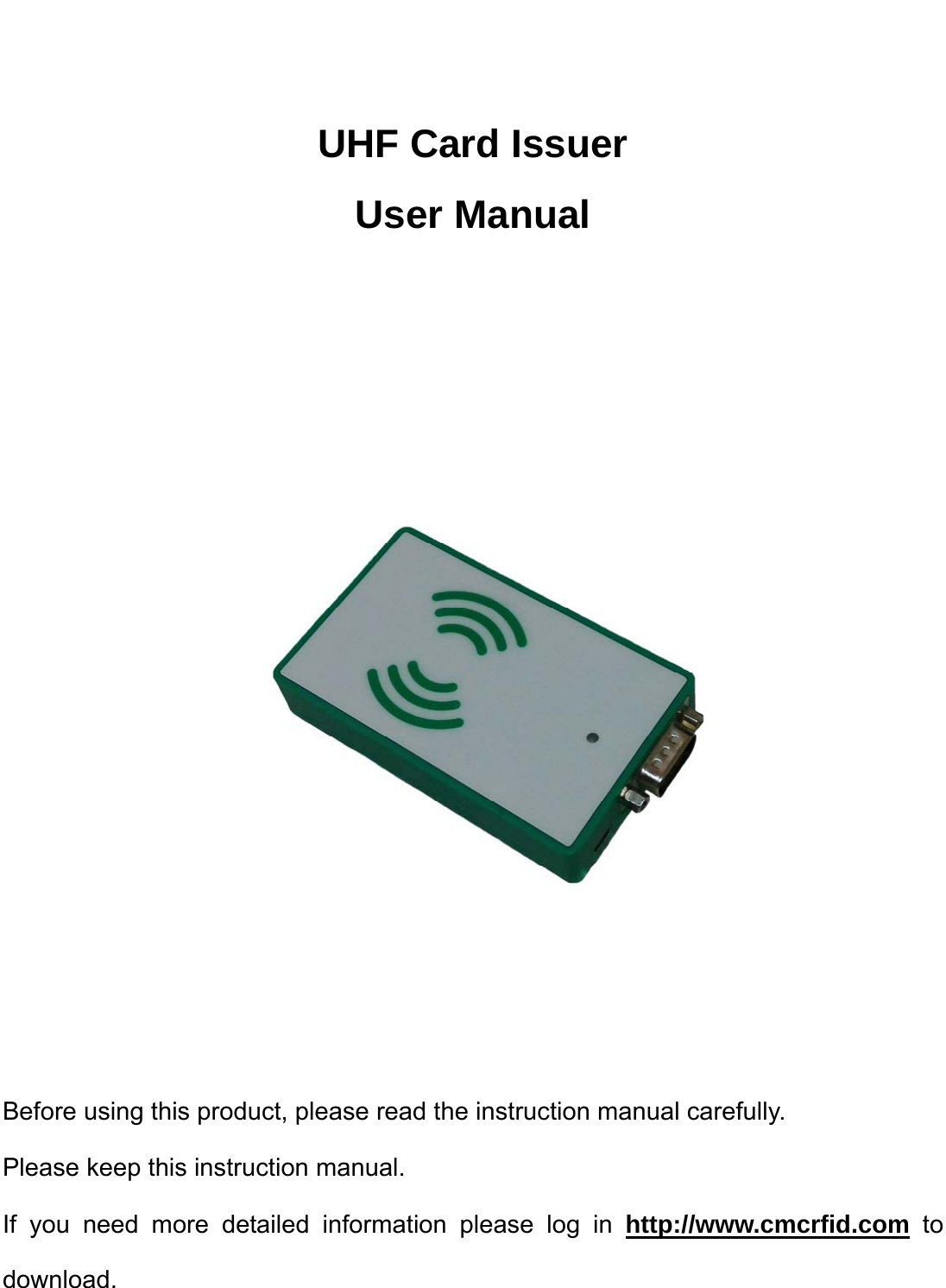
FUTAIHUA CMC187 UHF Card Issuer User Manual CMC187 Manual

FUTAIHUA INDUSTRIAL (SHENZHEN) CO.,LTD. UHF Card Issuer CMC187 Manual

15_CMC187 UserMan,r1

   UHF Card Issuer User Manual        Before using this product, please read the instruction manual carefully. Please keep this instruction manual. If you need more detailed information please log in http://www.cmcrfid.com to download.
  The first chapter  Quick guide 1.1 Product overview UHF Card Issuer is a small volume of UHF desktop, support ISO18000-6C protocol, has advantages of low power   consumption, easy to embed, high performance antenna, with built-in support USB and RS232 communication mode. Product application:  Stock-taking   Entrance guard system   Asset tracking management Product features:   Support for EPC C1 G2(ISO 18000-6C)protocol   Read/write operation reliability, high cost performance   Read distance of up to 80cm(with tag)   Low power consumption, the rated working current is 500mA Performance indicators Specification Protocol standard  EPC C1 G2(ISO18000-6C) Operation frequency America:902MHz~928MHz (Default) European:865MHz~868MHz China:920MHz~928MHz (The operation frequency is default parameter which cannot be modified to operate outside its authorization.) gain 0dBi Polarization mode  Linear polarization Power Consumption  Max 2.5W Power Through USB port  Identification Range  read≤80cm; writing≤20cm(depending on lable) Interface form  USB Mini, RS232 Output Power  23dBm(software is adjustable,1dBm step by step) Physical specifications Weight 94g Dimensions 92*56*17mm Out case  Metal profiles and Engineering plastics Environmental specifications Operating Temperature  -20℃~50℃ Storage Temperature  -40℃~85℃ Storage Humidity  5%~95% non-condensing
    1.2 UHF Card Issuer section function:     Card Issuer positive schematic diagram:  Card Issuer profile schematic diagram:      1.3 Product size chart (mm)  1.4 Standard accessories Project Number Remarks Host 1  UHF Card Issuer USB line  1  USB Mini  1.5 Install and use maintenance matters needing attention 1.    Please use the standard accessories; 2.  The authorized person shall not by himself to modify equipment, decomposition and assembly; Otherwise the warranty will be Cancelled; 3.    Please do not install the equipment storage or in direct sunlight, humidity condensation and other heat source location;   Here is a label that: 1. USB interface 2.  Serial port interface(RS232) Here is a label that: 1.  The antenna inductive zone 2. Power light
  The second chapter      Use of RFID demonstration 2.1    UHF Card Issuer System architecture: UHF Card Issuer via USB/RS232 Serial interface is connected to a PC, UHF Card Issuer using a USB power supply directly; With the corresponding Demo software can operate to read labels and so on; If you need more detailed UHF issuing organ and                                                                                             the PC communication protocols, please refer the documentation “communication protocols”, System architecture signal as shown in the below:                                                                                              System architecture diagram 2.2  Presentation tools Name Specifications Number UHF Card Issuer  100mm*62mm*18mm 1 USB lime  USB to Mini  1 Label UHF some computer / 1 2.3    Install the USB driver 1.  Right click on the “my computer” choose   “management” options → click “Device Manager” and click on the “other devices” drop-down box; As shown in figure2.1:                                                                                                              Figure 2.1  2.  Double-click in the “other devices” drop-down box to choose “HARVEMAC” option → click the “reinstall driver” → check “from the list, or specify the location to install (high Level)” option → click “next” button → click “browse” button to select store path of “ uhf_usb_driver ” file → click “next” button. Install the USB driver to install the driver after the completion of the click “finish” button to close the wizard; Operating procedures are shown in figure 2.2 below: UHF Card Issuer USB RS232 UHF  RFID label Computer/Industrial
             Figure 2.2 2.4 Supporting PC software instructions: UHF Card Issuer can use the USB interface communication, “URAT serial communication methods” two kinds of communication methods; “USB cable    and RS232 serial port connected to the computer ”; 1. Open the computer,ultra-high frequency card through USB cable    and RS232 serial port connected to the computer(only use “URAT” serial interface communication way to connect the serial port),UHF Issuer using USB interface power supply (card device connected to the computer after the success,the power indicator red light); 2.  Double-click to open the computer “UHFDemoV1.76.2”folder into the interface shown in 2.3:  Figure 2.3
  3.  See computer port number :right-click on the “my computer” icon to click to choose “management” option, →click select “device manager” options→ click “port (COM and LPT)”option drop-down box view of “communication port(COM)”;In order to enter 2.4 as shown in the following interface:               Figure 2.4 4.  Set equipment port (The port must be same of computer): use “notepad” opened the way to open “RFIDcomm.cfg”document→Settings equipment port (The port must be same of computer); In order to enter the following interface is shown in figure 2.5 (set successfully save it, close the text box):  Figure 2.5   5.  After setting the “COM”, click in the interface is shown in figure 2.1“ UHFDemoV1.76.2.exe”software; Into the following basic operation is shown in figure 2.6 interface:
        Figure 2.6 Icon shows Open:         Open card of card function Closed:        Close the issuing organ for card function Version:       The issuing of the firmware version number PWM:         Set card issuer’s duty ratio of output power (including duty than to have two options “0-2”optional;“0” is issuing unit output power have been open, “1” is the card output power on and off the duty ratio of more than 100 milliseconds to 400 milliseconds  ,“2”is the card output power on and off the duty ratio of more than 100 milliseconds to 500 milliseconds,the default is“0”mode) Power ( dBm):        Setting the output power of the issuing value (the default is 23“dBm”) Update the set:      Update the settings of the issuing power output value TO UART:      UART serial port communication (click on this button to select the UART serial port communication) TO USB:       USB interface communication (click the choose to use the USB interface communication) Clear:         Remove the label data Inc Once:          Click this button, the device will search tags automatically stop after 2s card Inventory:    Click this button, the device will always find the card Stop:         Click this button, the device will stop find the card Speed:        Issuing a second search to the tag number    Language settings: English/simplified Chinese/traditional Find card display area
  6.    Click “Open” button, open the card for card function; After the open success, the system will automatically obtain the card device firmware version number, he lower left corner will be prompted to “Host To MAC Interface: …”(when for “USB Interface communication”, indicates that “Host To MAC Interface:USB”; As for “UART serial interface communication mode”, suggests “Host To MAC Interface:UART”; And click “TO UART”/“TO USB” button can switch card, communication methods, and then click “Open” button); As shown in figure 2.7:   图2.7 1) Find card operation a.  Click “Open” button to open the issuing organ for card, will be to the operation of UHF tag on card issuer antenna sensor area; click “Inventory” / “Inv Once” button to card; When the card is found to label, “found card display area” display for the green and will search the information of the label of the display on the right side box , card of the power indicator blue light and buzzer will have prompt; When the card is more than 2 seconds are not search to label “find card display area” shows in red;As shown in figure 2.8:  Figure 2.8 b.  If you need to stop issuing organ for card function, click the “Stop” button to stop finding cards;  2) Reading and writing card operation Click“Open”button to the issuing organ for card,click on the “Tag Access” button to enter the following interface is shown in figure 2.9:   Figure 2.9
  Icon shows Password:          Tag password (The default is“00 00 00 00”) Bank:          Tag storage areas (including RESERVED, EPC, TID, USER; general user operations for the  EPC area) Begin:         To the starting address of operation area, the unit of word (2 bytes) (include “0-15”16 numerical EPC operation area will this value is set to 2) Length:         To read and write tags information length, the unit for word (2bytes) (include“1-15”15 numerical;                                   Tag EPC user operational capacity is 496bits, namely 31 word (see tag EPC length) Data:           Data show/edit box Read:           Read the tag information Write:           Write tag information  Read the card operation: Set to access the Bank, Begin, Length and other related parameters, UHF tag set   after the completion of the will to operate on the issuing of the antenna. Should area, click the “read” reading an   and writing card interface button toread the tag informantion reads the tag after the success of the information, the   corresponding tag information. Displayed in the “data” in the edit box and are displayed in the lower left corner   “Read the Tag OK”; As shown in figure 2.10:  Figure 2.10  Write card operation: Set to access the Bank, the Begin, Length and other related parameters, UHF tag set after   the completion of the will to operate on the issuing of the antenna. Should be area, in the “data” in the edit box   editor to write the tag information, click on “write” button to write the required information, written into work after the   lower left corner tip “Write OK” and displays the information write (when need to write information on tag for   peration, proposed to HF frequency standard. Sign the induction area, close to the issuing of antenna can   improve the success rate of written information; As shown in figure 2.11:   Figure 2.11 3) Check the operation record A.  Click on the “Log” button enter into operation can check card device operation records; As shown in  figure 2.12:  Figure 2.12  B. In the interface of operating records, check the “automatic storage operation record”。
   Appendix  一  UHF Card issuer common troubleshooting                           1.  Unable to open the UHF issuing organ for card function: A.  Please check whether the equipment and computer lines to connect USB and serial port; If not connected, please connect the USB cable and the serial port. B.  Please check equipment port number is consistent with the computer’s port number; If not consistent, please set the device port. C.  Please check whether the equipment install the USB driver; If not, please install the USB driver.  2.  Unable to search to tag: A.  May be output value of the equipment is too low, please send equipment power output value is set to “23dBm”. B.  May be a UHF tags have been damaged,please replace the UHF tags. Appendix 二 After-sales service commitment:   Product warranty period is one year, without damage to natural disaster and man-made factors, during the warranty period free warranty;   Product once sold, except for product quality problem need to repair or replace, shall not return;   Due to artificial damage, guarantees the failure due to improper operation, the implementation of maintenance fee;
  FCC Statement This equipment has been tested and found to comply with the limits for a Class B digital device, pursuant to part 15 of the FCC Rules. These limits are designed to provide reasonable protection against harmful interference in a residential installation. This equipment generates uses and can radiate radio frequency energy and, if not installed and used in accordance with the instructions, may cause harmful interference to radio communications. However, there is no guarantee that interference will not occur in a particular installation. If this equipment does cause harmful interference to radio or television reception, which can be determined by turning the equipment off and on, the user is encouraged to try to correct the interference by one or more of the following measures:   —Reorient or relocate the receiving antenna. —Increase the separation between the equipment and receiver.   —Connect the equipment into an outlet on a circuit different from that to which the receiver is connected.   —Consult the dealer or an experienced radio/TV technician for help.    FCC Radiation Exposure Statement   This device complies with FCC radiation exposure limits set forth for an uncontrolled environment and it also complies with Part 15 of the FCC RF Rules. This equipment must be installed and operated in accordance with provided instructions and the antenna(s) used for this transmitter must be installed to provide a separation distance of at least 20 cm from all persons and must not be co-located or operating in conjunction with any other antenna or transmitter. End-users and installers must be provide with antenna installation instructions and consider removing the no-collocation statement.  This device complies with Part 15 of the FCC Rules. Operation is subject to the following two conditions: (1) this device may not cause harmful interference, and (2) this device must accept any interference received, including interference that may cause undesired operation.  Caution!   Any changes or modifications not expressly approved by the party responsible for compliance could void the user's authority to operate the equipment.

Navigation menu