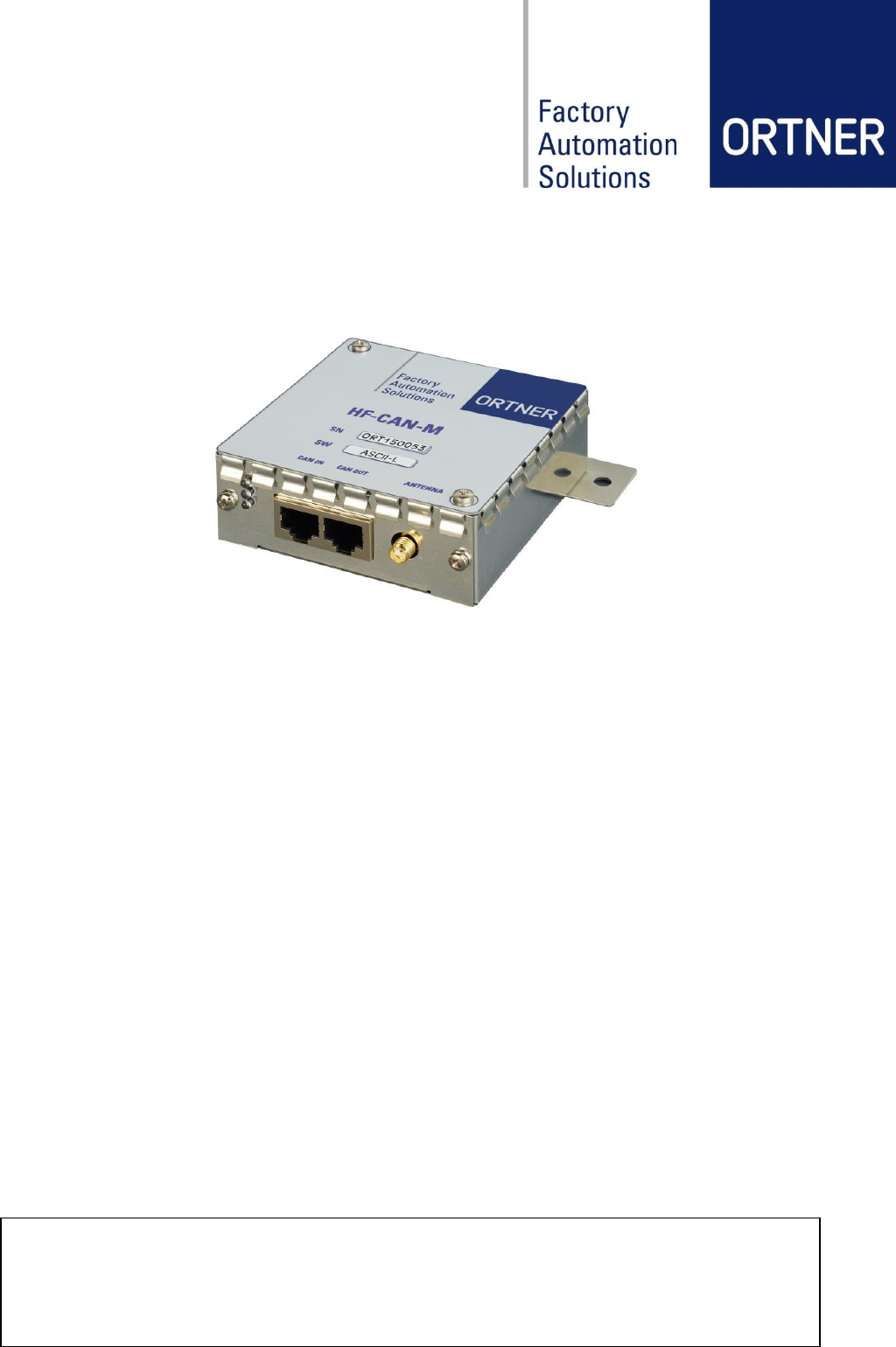
Fabmatics HF-1356-CAN High-frequency 13.56 MHz RFID read/write device, which provides a CAN bus interface and easy connection of multiple devices User Manual HF CAN M
Roth & Rau - Ortner GmbH High-frequency 13.56 MHz RFID read/write device, which provides a CAN bus interface and easy connection of multiple devices HF CAN M
YTV-HF-1356-CAN UserMan
www.rr-ortner.com
This document contains confidential information and has been provided by Roth & Rau - Ortner GmbH for the purpose of evalu-
ation. No part of this document may be copied, reproduced, disclosed, or transferred by any means without prior written consent
of Roth & Rau - Ortner GmbH. Roth & Rau - Ortner GmbH reserves the right to make updates to the information in this docu-
ment without prior notice or approval from others. Please consult the author of this document to ensure that you have the latest
revision.
HF-CAN-M
User Manual
Revision: 03
Document date: August 25, 2015
Revision: 03 HF-CAN-M User Manual Page 2 of 30
Revision History
#
Date
Revision
Description
Editor
1
14.01.2015
01
initial version
JGE
2
19.03.2015
02
Add technical parameters, add FCC
NEL
3
25.08.2015
03
Add Operational description (chapter 2.2)
NEL

Revision: 03 HF-CAN-M User Manual Page 3 of 30
Content
1 General Information .........................................................................................................5
2 Product Overview ............................................................................................................6
2.1 General Function ..................................................................................................6
2.2 Operational description ........................................................................................6
2.2.1 How the device operates? ....................................................................................6
2.2.2 How is the device modulated? ..............................................................................6
2.2.3 Short description of the device .............................................................................6
2.2.4 Pulse rate .............................................................................................................6
2.2.5 Signal type ...........................................................................................................7
2.2.6 Information being sent ..........................................................................................7
2.3 Product Revision ..................................................................................................7
3 Safety instructions ...........................................................................................................8
3.1 Depiction ..............................................................................................................8
3.2 General Safety Instructions ..................................................................................9
3.3 Qualified Personnel ............................................................................................10
3.4 Intended use ......................................................................................................10
4 Compliances ..................................................................................................................11
4.1 USA Federal Communications Commission (FCC) ............................................11
4.1.1 Compliance ........................................................................................................11
4.1.2 Antenna Requirements .......................................................................................11
4.1.3 Labeling Requirements ......................................................................................11
4.2 Europe CE-Conformity .......................................................................................11
5 Construction Design ......................................................................................................12
5.1 General Layout / Design .....................................................................................12
5.2 Product Information Label ..................................................................................12
5.3 Engineer Drawing HF-CAN-M ............................................................................13
6 Hardware Design ...........................................................................................................14
6.1 Technical Data ...................................................................................................14
6.2 Operation LEDs ..................................................................................................14
6.3 Reading and Writing Ranges ..............................................................................15
6.3.1 Example range measures with Antenna ANT-HF-87-54E ...................................15
7 Hardware Configuration .................................................................................................16
7.1 Address Configuration ........................................................................................16
7.2 Connector Pinouts: CAN IN/OUT Connector ......................................................16
7.3 Reading Range configuration .............................................................................17

Revision: 03 HF-CAN-M User Manual Page 4 of 30
8 Installation .....................................................................................................................18
8.1 General Connection ...........................................................................................18
8.2 CAN-BUS / Power Connection Layout (CAN2Web Advanced MINI) ..................18
8.3 CAN-BUS / Power Connection Layout (CAN2Web Advanced MAXI) .................19
9 Software Configuration ..................................................................................................20
9.1 Content global.cfg at CAN2Web Advanced ........................................................20
9.2 HF relevant settings in global.cfg at CAN2Web Advanced .................................20
9.2.1 Parameter transponder_types ............................................................................20
9.2.2 Parameter iso15693_rf_mode ............................................................................20
10 Operation.......................................................................................................................21
10.1 Start-up procedure .............................................................................................21
10.2 During operation .................................................................................................21
10.3 Shutdown ...........................................................................................................21
11 Maintenance ..................................................................................................................22
11.1 Cleaning .............................................................................................................22
11.2 Error Handling ....................................................................................................22
12 Service Information ........................................................................................................23
12.1 Contact...............................................................................................................23
12.2 Support ..............................................................................................................23
12.3 Return Material Authorization (RMA) ..................................................................23
12.4 Warranty ............................................................................................................24
12.5 Disposal .............................................................................................................24
12.6 Spare Parts ........................................................................................................24
12.7 Accessories & Spare Part Overview ...................................................................25
13 Appendix .......................................................................................................................28
13.1 Europe CE-Conformity .......................................................................................28
13.2 Glossary .............................................................................................................29
13.3 Related documents ............................................................................................29
Revision: 03 HF-CAN-M User Manual Page 5 of 30
1 General Information
This manual is the original operation instruction for the high frequency RFID reader device
HF-CAN-M.
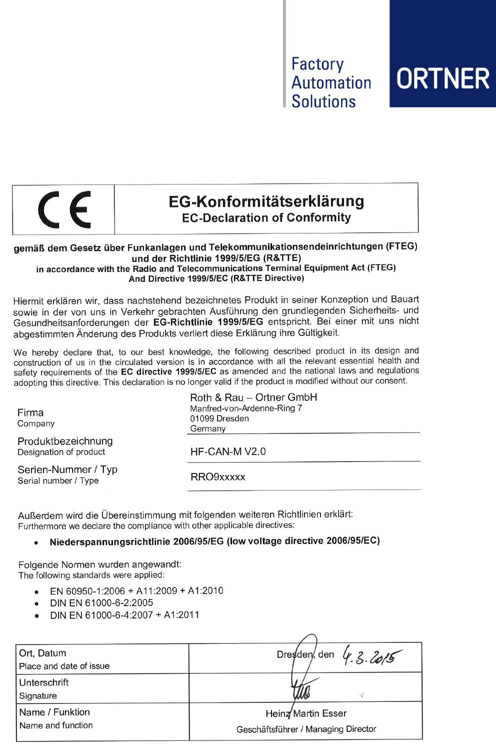
The declaration of conformity of the product is included in the appendix of this manual.
The operating instructions should allow the operator the proper and safe operation and warn of
foreseeable misuse. It is intended for the professional staff of the operator.
These instructions must be retained for future reference!
CAUTION!
Keep these instructions! Access to the operating instructions by the operator and
maintenance personnel must be ensured at all times during installation, operation and
troubleshooting!
A copy of the instructions must therefore be stored in a suitable and accessible location!
The explanation of hazard symbols is contained in section 3.1.
Revision: 03 HF-CAN-M User Manual Page 6 of 30
2 Product Overview
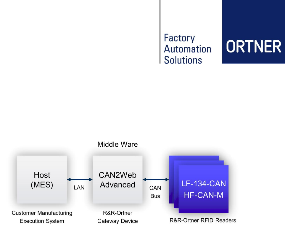
2.1 General Function
The HF-CAN-M reader is designed for operate in ID reader networks, based on CAN-Bus. For
connecting the reader network to a host system (MES), Roth & Rau – Ortner
provides CAN2Web middleware components also.
The HF-CAN-M reader is an RFID module which supports ISO 15963, I-code transponders and
Infineon transponders my-d vicinity version 2.0. The module contains a CAN uplink for establish
the connection to the CAN-bus controller and a downlink for extending the ID reader network.
Features:
- CAN interface (CAN IN and CAN OUT)
- Reads and writes ISO 15963, I-code transponders and my-d vicinity version 2.0 transpond-
ers
- Powerful and efficient output stage
2.2 Operational description
2.2.1 How the device operates?
The HF-CAN reader slave device reads ISO15693 (same as ISO18000-3 mode 1) transponder
on request from a master device (CAN2Web box).
2.2.2 How is the device modulated?
The reader sends out a charge burst of 13.56MHz as long as needed to read the transponder
(depending on command). The answer to and from transponder is ASK or FSK depending on
selectable RF mode.
The modulation follows ISO18000-3 mode 1 (ISO15693).
2.2.3 Short description of the device
RFID reader for ISO18000-3 Mode 1 HF transponder
2.2.4 Pulse rate
See ISO18000-3 Mode 1
Revision: 03 HF-CAN-M User Manual Page 7 of 30
2.2.5 Signal type
ASK or FSK signal from transponder
ASK signal from reader
2.2.6 Information being sent
8bytes of data + status + CRC
2.3 Product Revision
Available Product Versions
Product Revision
Hardware Revision
(PBC)
HF-CAN-M
2.0
1.1
Product Code Description:
HF - CAN - M - V2.0
Frequency Spectrum Interface Metal case Product Revision
Available Software Versions:
Software Code
Description
HF CANopen
reader trampoline
0x80008000.hex
11.02.2015
Device will be controlled completely by CAN2Web Box or CAN-
Controller. Using SDO CAN protocol.
hf reader boot-
loader.hex
06.02.2015
Devices can be updated over CAN2Web Box.
NOTE!
The product revisions are denoted by revision numbers. The respective revision num-
bers of the three components of each product belong to the product revision numbers:
Hardware, Software, and Design.
Each product revision number is distinctive and denotes a particular design or a par-
ticular function of the product. Changes in design necessitate a new product revision
number. Changes in the two product components hardware and software may, but
don´t have to result in a new product revision number.
Revision: 03 HF-CAN-M User Manual Page 8 of 30
3 Safety instructions
In this chapter, universal and general safety instructions to be followed, are listed and ex-
plained. The user will be informed about risks, residual risks and risk mitigation measures.
In addition, action- and situation-related safety notes are placed in the appropriate sections in
the operating instructions.
3.1 Depiction
DANGER!
This symbol indicates a serious risk to life and health of personnel. Follow these
guidelines, and act with extreme caution in these cases!
CAUTION!
This symbol indicates danger to life and health of personnel. Follow these guidelines,
and act with extreme caution in these cases!
ATTENTION!
This symbol refers to slight wound or damage to the product, as well as from poten-
tially unsafe operation.
NOTE!
Notes serve as a warning against operating errors and to highlight important issues,
as well as for better understanding of the product.
Revision: 03 HF-CAN-M User Manual Page 9 of 30
3.2 General Safety Instructions
The HF-CAN-M High Frequency RFID-reader corresponds to the prior art and the approved
safety rules. Nevertheless, there are potential risks.
The product may only be operated in good condition in accordance with the present operating
instructions.
CAUTION!
Read all safety and operating instructions and make sure they have been understood,
before using this product! The product may only be used in technically perfect condi-
tion and in accordance with all sections of the operating instructions!
The following safety instructions are intended to supplement the applicable accident prevention
regulations and laws. Existing safety regulations and laws must be complied in any case!
CAUTION!
Repairs and modifications inside the product are NOT destined for the operator. The
casing only must be opened by a qualified electrician or by Roth & Rau - Ortner.
CAUTION!
Products may not be converted or modified by the operator. Otherwise, the warranty
expires.
CAUTION!
When opening the housing, be careful to avoid damage to the product. Do not use
sharp objects and protect your eyes from possible burst off parts!
ATTENTION!
Make sure the device is powered off before remove the top cover!
ATTENTION!
HF-CAN-M devices may be operated with approved equipment only. Doing so may
cause a product defect or hazards (e.g. fire or electric shock) during operation.
Available accessories of this product are listed in section 12.7.
Only use extensions, accessories and connection cables which are approved by Roth & Rau -
Ortner. For questions about approved accessories, please contact our sales department (see
section 12.1).
NOTE!
If you remove a cable, pull the plug, not the cable itself. Make sure that any connect-
ors are attached properly, to avoid damage of the pins. If a cable is to be connected,
ensure that there are no bent pins on the connectors.
In case of mechanical damage to the product, the device or system must be disconnected from
the power supply!
Revision: 03 HF-CAN-M User Manual Page 10 of 30
3.3 Qualified Personnel
The intended users of the product are factory operating personnel (system operator) and
maintenance personnel.
It is assumed that all users are familiar with the function and the risks of the entire system be-
fore use.
All operators should be trained in at least the following topics:
- Basic functions of the system in which the HF-CAN-M readers are installed
(operator)
- Manual (operator)
- Software for configuration (set-up and maintenance staff)
The manual is designed for trained staff. The device may only be installed and serviced by Roth
& Rau - Ortner or especially therefor trained staff.
CAUTION!
Interventions and bug fixes that are not described in this manual may only be per-
formed of Roth & Rau - Ortner.
CAUTION!
Standard regulations for safety must be observed!
ATTENTION!
Operation and troubleshooting must be carried out by specially trained staff.
Basic requirement is that the instruction manual was read and understood. If you are
unsure about necessary qualifications therefor, please contact Roth & Rau - Ortner!
3.4 Intended use
This product was developed for reading and writing the transponder types only, specified in this
manual. Proper antennas for reading and writing are antennas supplied by the manufacturer.
Never locate the reader with antenna so that it is very close to or touching parts of the body
while transmitting.
This product is designed to be mounted and operated in an industrial environment as a built-in-
device only. It is not designed to be used as a stand-alone or a portable device in a non-
industrial environment, such as a household, automotive or open-air environment.
The device may be used no closer than 20cm to the human body.
Any use outside of the general conditions described in the existing instruction manual consti-
tutes improper use.

Revision: 03 HF-CAN-M User Manual Page 11 of 30
4 Compliances
4.1 USA Federal Communications Commission (FCC)
HF-CAN-M is a Class A digital device. It is a digital device that is marketed for use in a com-
mercial, industrial or business environment, exclusive of a device which is marketed for use by
the general public or is intended to be used in the home.
4.1.1 Compliance
The product complies with FCC Subpart C – Intentional Radiators §15.201 and with Subpart J –
Equipment Authorization Procedures § 2.209, when used for its intended purpose. All emissions
are at least 40 dB below the limits in § 15.209 and are verified pursuant to the procedures in
FCC Subpart J of part 2. These limits are designed to provide reasonable protection against
harmful interference when the equipment is operated in a commercial environment. This equip-
ment generates, uses, and can radiate radio frequency energy and, if not installed and used in
accordance with the instruction manual, may cause harmful interference to radio communica-
tions. Operation of this equipment in a residential area is likely to cause harmful interference in
which case the user will be required to correct the interference at his/her own expense.
4.1.2 Antenna Requirements
The antenna is removable and does not employ a unique connector; however, the device is
professionally installed and maintained. Therefore, the described HF Reader complies with
FCC15.203.
4.1.3 Labeling Requirements
The described HF Reader is not large enough to accommodate a label with the standard FCC
compliance statement. It is therefore provided here as follows:
This device complies with Part 15 of the FCC Rules. Operation is subject to the following two
conditions: (1) this device may not cause harmful interference, and (2) this device must accept
any interference received, including interference that may cause undesired.
For further information please see chapter 5.2.
4.2 Europe CE-Conformity
The EC-declaration of conformity is included in appendix in chapter 13.1.
ATTENTION!
Changes or modifications not expressly approved by the party responsible for compli-
ance may void the user’s authority to operate the equipment.
Revision: 03 HF-CAN-M User Manual Page 12 of 30
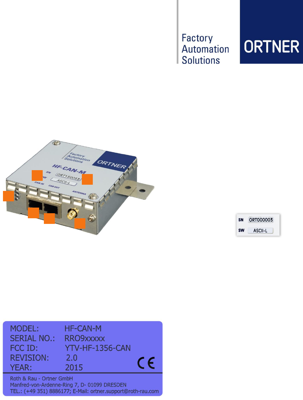
5 Construction Design
5.1 General Layout / Design
Following figures show the RFID reader HF-CAN-M.
All versions of the HF-CAN-M are built in a tin plate case.
1
CAN-Bus/Power In
RJ45
2
CAN-Bus/Power Out
RJ45
3
External Antenna
SMA
4
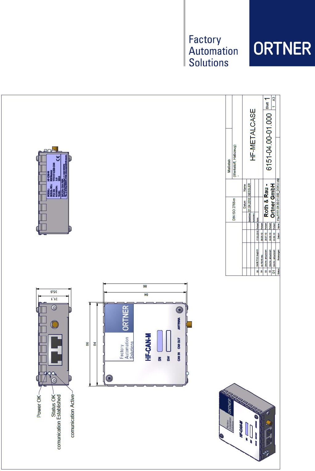
Operation LEDs:
- RX/TX
- Status OK
- Power OK
A
Serial number
B
Software type/version
5.2 Product Information Label
The product information label is located on the back side (see also engineer drawing in chapter
5.3) and contains the product name (Model), product revision, serial number and year of pro-
duction. Serial number is RRO9xxxxx starting with 2012. Before 2012 it was ORT15xxxx. Fur-
thermore the FCC number YTV-HF-1356-CAN is listed and the CE-mark.
The dimension of label is 21,5mm x 46 mm.
2
1
3
4
A
B
Revision: 03 HF-CAN-M User Manual Page 13 of 30
5.3 Engineer Drawing HF-CAN-M
Revision: 03 HF-CAN-M User Manual Page 14 of 30
6 Hardware Design
6.1 Technical Data
Dimensions (w h d)
90 x 90 x 30 mm
Weight
185,4 g
Case Material
Tin plate
Operating temperature
5 °C to +50 °C
Storage temperature
-25 °C to +50 °C
Voltage power supply
24 V/DC ±3%
Power consumption
Standard antenna
2.7W reading / 0.5W stand-by (typical)
Power consumption
maximum
6.0W reading ANTD-HF-120-120E
Antenna
13,56 MHz 50 Ohm impedance 1 Watt
RFID frequency
13,56MHz
Readable transponder
types
ISO 15963; ISO 18000-3 (e.g. card RI-TRP-W4FF; disk RF-PT-
25-10)
IFX SRF55V02P (e.g. card my-d vicinity)
MTBF
≥ 40,000 h
MCBF
≥ 1,000,000 reading cycles
CAN-Bus speed
adjustable up to 1 Mbit/s, typical 100 Kbit/s
Max. CAN cable length
100 m
Available CAN protocols
SDO
Available Connectors
CAN In (RJ45) CAN-Bus / power in
CAN Out (RJ45) CAN-Bus / power out
Antenna (SMA) 50 ohm impedance
6.2 Operation LEDs
The table below describes the meaning of each status light on top of the device cover.
LED name
Color
Description
RX/TX
Yellow
CAN-bus data transfer is active
Status
Red
communication with master established, initialized
Power
Green
/DC power ok
Revision: 03 HF-CAN-M User Manual Page 15 of 30
6.3 Reading and Writing Ranges
The provided reading ranges shown here and in their respective Antenna datasheets are meas-
ured with best conditions. In real environment the ranges can be differ due to disturbing material
like metal or any kind of electro-magnetically fields near to the Antenna location. Please thor-
ough improve the conditions before make final decisions about the Antenna location.
Writing ranges in general are approximately 60% of the reading ranges.
For detailed information about individual range characteristics of available Antenna-Types
please refer to the corresponding data sheets like ANT-HF-25E / ANT-HF-33E / ANT-HF-87-
54E.
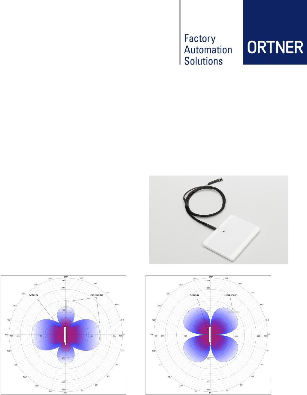
6.3.1 Example range measures with
Antenna ANT-HF-87-54E
For the external high frequency RFID PCB an-
tenna for 13.56 MHz band, see picture above,
the antenna resonance frequency can be adjust-
ed through a hole in the housing. A detuning of
the antenna by environment can thus be com-
pensated.
Antenna aligned parallel to the ID Tag card,
reading range up to 150mm
Antenna aligned orthogonal to the ID Tag
card, reading rage up to 140mm
Revision: 03 HF-CAN-M User Manual Page 16 of 30
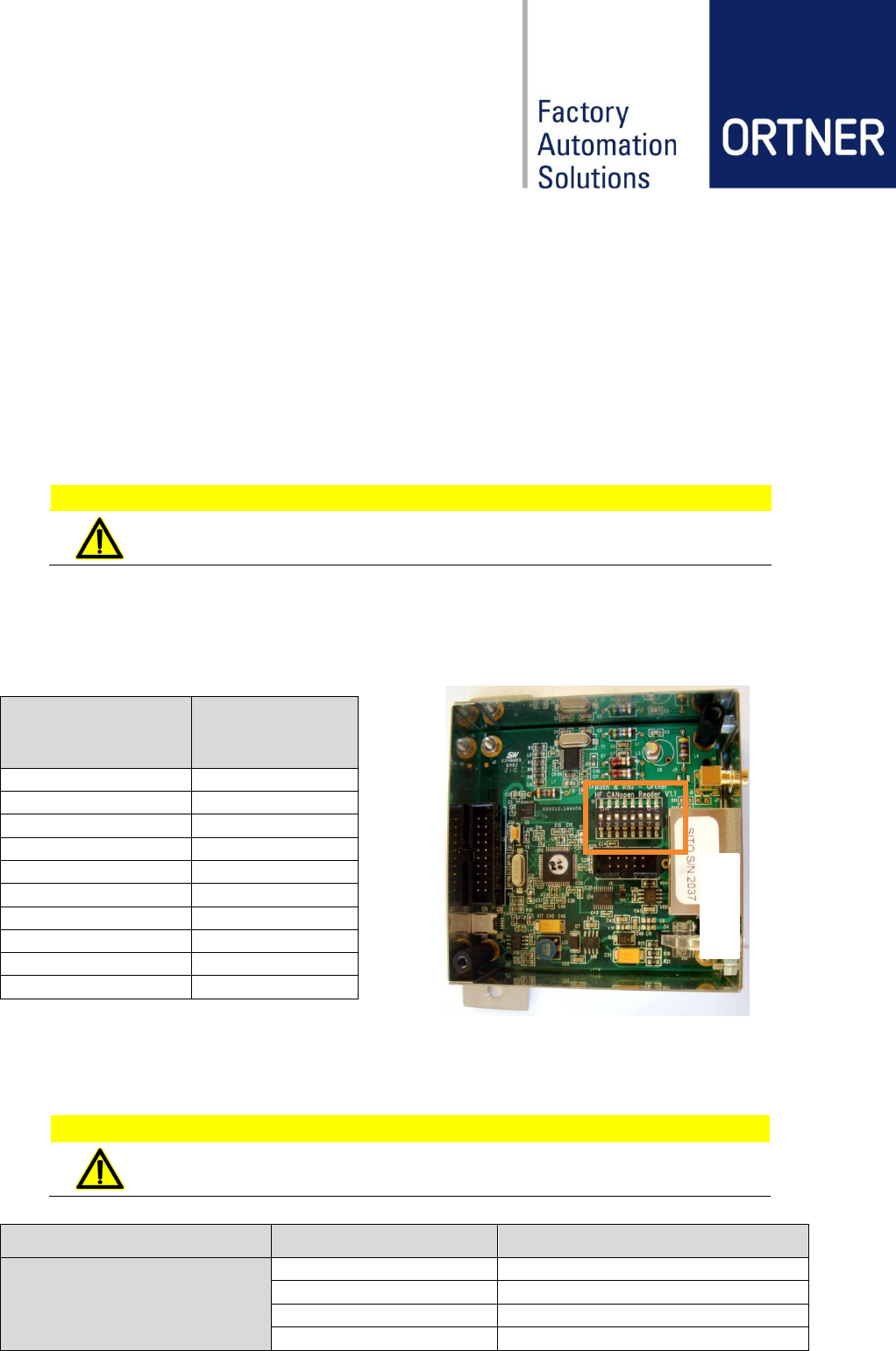
7 Hardware Configuration
7.1 Address Configuration
The CAN-ID will be read on every power up cycle. If the CAN-ID became changed during power
on, the device must be restarted by power off and on again to be able to use the new ID.
To change the CAN-address it’s necessary to open the device by removing the top cover. Turn
the unit to the back side and start do bend one side panel of the top cover away from the bottom
part, during pulling them apart. Repeat the same action for both sides and lift off the top cover
completely thereafter. This can done by hand, tools are not necessary.
ATTENTION!
Make sure the device is powered off before remove the top cover!
The CAN-bus ID can set from 1 to 127 in binary code by using the DIP-Switches No.1 to 7.
The DIP-Switch No.8 has to be off at all time.
Following table show some configuration examples of how to set the CAN-ID (reader address):
The CAN-ID block uses an 11 Bit identifier, not the extended 29 Bit identifier.
7.2 Connector Pinouts: CAN IN/OUT Connector
CAUTION!
If custom accessory will be connected, make sure this is carried out by qualified per-
sonnel only, to prevent electrical damage to the device!
Connector
PIN number
Description
8P8C (RJ45/48)
1
CAN high
2
CAN low
3,6,7
GND
4,5,8
24 V/DC
DIP-Switches
1 2 3 4 5 6 7 8
CAN-ID/ reader
address
1 0 0 0 0 0 0 0
1
0 1 0 0 0 0 0 0
2
1 1 0 0 0 0 0 0
3
0 0 1 0 0 0 0 0
4
1 0 1 0 0 0 0 0
5
0 1 1 0 0 0 0 0
6
1 1 1 0 0 0 0 0
7
0 0 0 1 0 0 0 0
8
…
…
1 1 1 1 1 1 1 0
127
Revision: 03 HF-CAN-M User Manual Page 17 of 30
7.3 Reading Range configuration
In order to define and position the HF antenna, a so called HF Detector C was developed, see
the following picture.
The HF Detector C corresponds in design to transponder cards ISO 15693. The LED of RF De-
tector C is illuminating depending on the surrounding RFID magnetic field strength. Is the detec-
tor in a stronger magnetic field, the LED is illuminating stronger and vice versa. The electronics
are designed so that the LED starts illuminating, when the RFID magnetic field strength corre-
sponds to the strength required for sending data from transponder.
For more detail please see datasheet of HF Detector C.
Revision: 03 HF-CAN-M User Manual Page 18 of 30
8 Installation
8.1 General Connection
All ID readers will be connected through CAN-bus to the CAN2Web-Advanced box.
Depending on your CAN2Web Version (MINI/MIDI/MAXI), a maximum number of 8 (MINI) or 50
(MIDI, MAXI) ID readers can be connected to one box.
If more than 10 reader devices (MIDI, MAXI) need to be connected, a special CAN-bus power
splitter needs to be installed. Please refer to the separate data sheet of CAN-POWER-
INJECTOR and the user manual of CAN2Web Advanced.
Before power on the ID-reader Network, it’s necessary to make sure the CAN-ID (address) for
each ID-reader device is setup correctly like in the following figures.
Changing the CAN-IDs of each ID reader is explained in section 7.1.
NOTE!
The CAN2Web-Gateways are preconfigured with CAN-ID 0 – there is no need for
change. The readers usually will be delivered with preconfigured CAN-IDs depending
on customer requests.
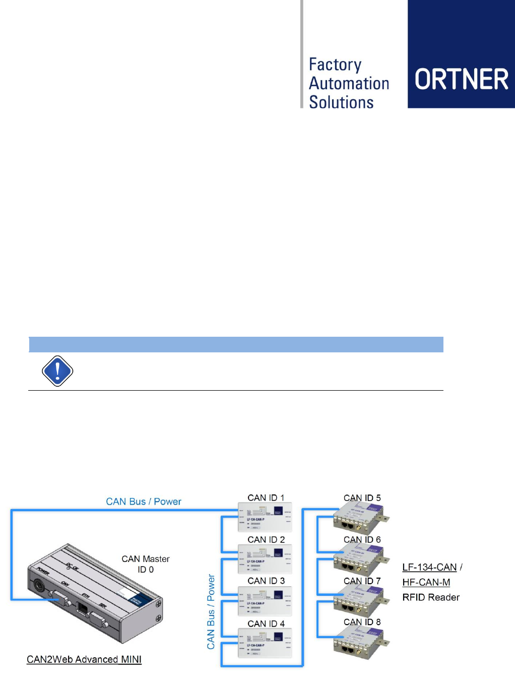
8.2 CAN-BUS / Power Connection Layout (CAN2Web Advanced
MINI)
Up to 8 CAN RFID-readers can be connected, depending on cable length of CAN-Bus. The
maximum cable length is 100 m.
Revision: 03 HF-CAN-M User Manual Page 19 of 30
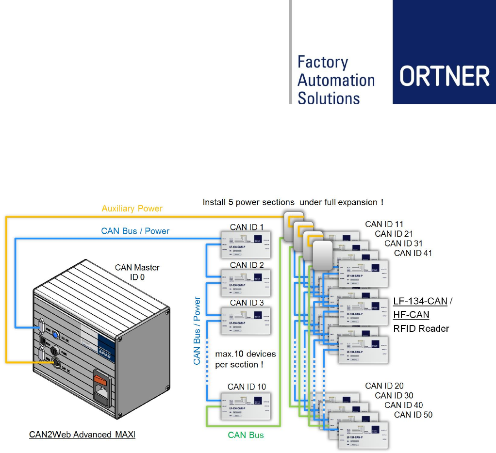
8.3 CAN-BUS / Power Connection Layout (CAN2Web Advanced
MAXI)
Up to 50 CAN RFID-readers can be connected, depending on cable length of CAN-Bus and
antenna type.
Revision: 03 HF-CAN-M User Manual Page 20 of 30
9 Software Configuration
This chapter serves to familiarize the user with software-related configuration.
The exact software configuration depends on the software or interface package which has been
ordered. Please refer to interface documentation for details.
9.1 Content global.cfg at CAN2Web Advanced
//set globals for all gateways
offline_time 30
gateway_one_rs232 0
transponder_type 3
max_socket_server 1
accept_tcpip_connection 1
auto_adjustment 1
iso15693_rf_mode 0x2c
// End of global.cfg
9.2 HF relevant settings in global.cfg at CAN2Web Advanced
9.2.1 Parameter transponder_types
Transponder type
Value at global.cfg
Transponder example
LF_SINGLE
0
(for LF single page transponders)
LF_MULTI
1
(for LF multi page transponders)
HF_ISO_15693
2
TI card RI-TRP-W4FF
HF_IFX
3
IFX card my-d vicinity v2.0 (SRF55V02P)
9.2.2 Parameter iso15693_rf_mode
RF Mode
Value*
RF Mode
Value*
HF_1OF4_10_FM_LOW
0x20
HF_1OF4_100_AM_HIGH
0x2E
HF_1OF4_10_FM_HIGH
0x22
HF_1OF256_10_FM_LOW
0x30
HF_1OF4_10_AM_LOW
0x24
HF_1OF256_10_FM_HIGH
0x32
HF_1OF4_10_AM_HIGH
0x26
HF_1OF256_10_AM_LOW
0x34
HF_1OF4_100_FM_LOW
0x28
HF_1OF256_10_AM_HIGH
0x36
HF_1OF4_100_FM_HIGH
0x2A
HF_1OF256_100_FM_LOW
0x38
HF_1OF4_100_AM_LOW
0x2C
HF_1OF256_100_AM_LOW
*at global.cfg
Revision: 03 HF-CAN-M User Manual Page 21 of 30
10 Operation
10.1 Start-up procedure
Before delivery, the product is factory-tested as part of the quality assurance throughout the
production process.
Start-up of the RFID system with HF-CAN-M is carried out by trained personnel (see chapter
3.3) Requirements for the start-up by the customer are:
- The user manual of reader and of used CAN2Web Advanced is available to the
start-up personnel.
- The mains supply is connected.
- The configuration in CAN2Web Advanced has been made.
Via the power switch on the CAN2Web Advanced box, the overall system and all connected
readers are supplied with the supply voltage (24 VDC) and the CAN bus signal.
NOTE!
The system needs approx. 3 seconds to be ready for operation!
10.2 During operation
After completing the configuration and the start-up, the product is in operation.
Switching or control operations are not required during operation.
10.3 Shutdown
The HF-CAN-M can be shut down for a longer period of time without any additional risks. No
special maintenance work is necessary during this period.
The decommissioning is performed by connecting off the CAN cable on the HF-CAN-M.
Revision: 03 HF-CAN-M User Manual Page 22 of 30
11 Maintenance
The plant operator is responsible for the maintenance.
11.1 Cleaning
Cleaning of the surfaces is possible with Isopropanol (IPA).
DANGER!
Before using IPA (Isopropanol), shut down any electrical power for the
system! Otherwise there is a potential high risk on fire outbreak, caused
by short circuit or heated components.
CAUTION!
Isopropanol (IPA) vapors are anesthetic. The contact causes irritation of
eyes and mucous membranes. Ensure adequate ventilation when han-
dling.
ATTENTION!
Before start working on the system, always check for mechanical damage and pay
attention to any unusual odors, discoloration and noises!
11.2 Error Handling
In case of serious system disorders please contact the Roth & Rau – Ortner Support:
Phone: +49 351 888 61 77 (only daytime CET)
Fax: +49 351 888 61 20
Mail: ortner.support@roth-rau.com
Revision: 03 HF-CAN-M User Manual Page 23 of 30
12 Service Information
12.1 Contact
Address Roth & Rau - Ortner GmbH
Manfred-von-Ardenne-Ring 7
01099 Dresden
GERMANY
Phone: +49 351 888 61 0 (only daytime CET)
Fax: +49 351 888 61 20
Mail: ortner.sales@roth-rau.com
Web: www.the-missing-link.com | www.rr-ortner.com
12.2 Support
For all purchased RFID components, RR-Ortner provides free phone and email support. This
includes support for components operation as well as support for the integration and installation
of components into customer equipment.
The phone support will be available at common working times between 8:00 am and 5:00 pm
CET. Beyond, a voice mail box is available.
Phone: +49 351 888 61 77 (only daytime CET)
Fax: +49 351 888 61 20
Mail: ortner.support@roth-rau.com
12.3 Return Material Authorization (RMA)
Before returning a defective device to Ortner, it is necessary to request a RMA number. This
process ensures the proper return of the product and enables a faster classification and repair
or replacement of the defective device. Please follow the below steps:
1. Please contact our support to get the RMA form and RMA number
2. Ortner generates a RMA number
3. Customer completes the RMA form by using the received RMA number
4. Customer ship the defective unit with attached RMA-Report to:
Roth & Rau - Ortner GmbH
Manfred-von-Ardenne-Ring 7
01099 Dresden
GERMANY
5. Ortner acknowledge the receipt and processing the RMA request
6. Returning the repaired or replaced device to Customer
IMPORTANT!
Please prominently display the RMA number on the packaging,
to allow us to serve you faster.
RMA
000-000-000
Revision: 03 HF-CAN-M User Manual Page 24 of 30
12.4 Warranty
The warranty period is 24 months and begins with the moment of delivery of the device as
proved by an invoice or other documents. The warranty includes the repair of all damages to the
device that occurs within the warranty period and which is evidently caused by faults of the ma-
terial or production defects.
The warranty does not include damages caused by incorrect connection, inappropriate handling
and non-observance of the technical reports.
12.5 Disposal
Within the European Union Roth & Rau – Ortner will take back any delivered equipment for dis-
posal. For further information on the return, please contact the Roth & Rau – Ortner Support.
NOTE!
For disposal the equipment by your own, make sure to observe all applicable laws.
12.6 Spare Parts
The components in our current array of products are available as spare parts to our customers.
In case of spare part requests for products which are already removed from our actual array of
products, Roth & Rau – Ortner requires detailed product information of the defective unit. All
components have an expected product lifetime of 10 years. For this time period we are able to
provide spare parts.
NOTE!
Before ordering spare parts, make sure to choose the right type (hardware / software)
of the considered unit. Search for the product information label.
Revision: 03 HF-CAN-M User Manual Page 25 of 30
12.7 Accessories & Spare Part Overview
Component
Description
Order Codes
HF-CAN-M
Multifunctional 13.56 MHz high frequency RFID-reader with tinplate
metal case. Multiple readers can be connected to one CAN2Web-
gateway by RJ45 CAN-bus cable.
HF-CAN-M
000562
Cable-ETH
CAN-bus cable for direct connection between all variants of Ortner
LF-/HF-RFID-readers. RJ45 to RJ45.
NOTE: The cable cannot be replaced by any Ethernet cable!
cable lengths will be customized
000144
Cable-CAN-SER
CAN-bus cable for connecting all versions of a CAN2Web-gateway
to the first ID-reader in a CAN-bus network.
DE9 to RJ45.
cable length 1.5m
000130
CAN2Web Advanced
MINI
Multifunctional CAN-bus to Ethernet gateway device to connect Ort-
ner RFID-readers to a host system. Supplies up to 8 devices.
CAN2Web-A-MINI 64
w/o base plate
000076-64MB
CAN2Web-A-MINI 64
with base plate
000170-64MB
CAN2Web Advanced
MIDI
Multifunctional CAN-bus to Ethernet gateway device to connect Ort-
ner RFID-readers to a host system. Supplies up to 25 devices with
integrated 50W wide range switched mode power supply.
CAN2Web-A-MIDI 64
000079-64MB
Revision: 03 HF-CAN-M User Manual Page 26 of 30
Component
Description
Order Codes
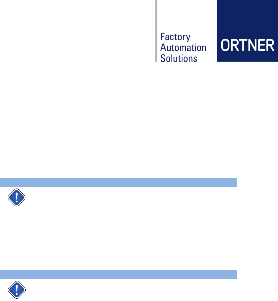
CAN2Web Advanced
MAXI
Multifunctional CAN-bus to Ethernet gateway device to connect Ort-
ner RFID-readers to a host system. Supplies up to 50 devices with
integrated 100W wide range switched mode power supply.
CAN2Web-A-MAXI 64
000078-64MB
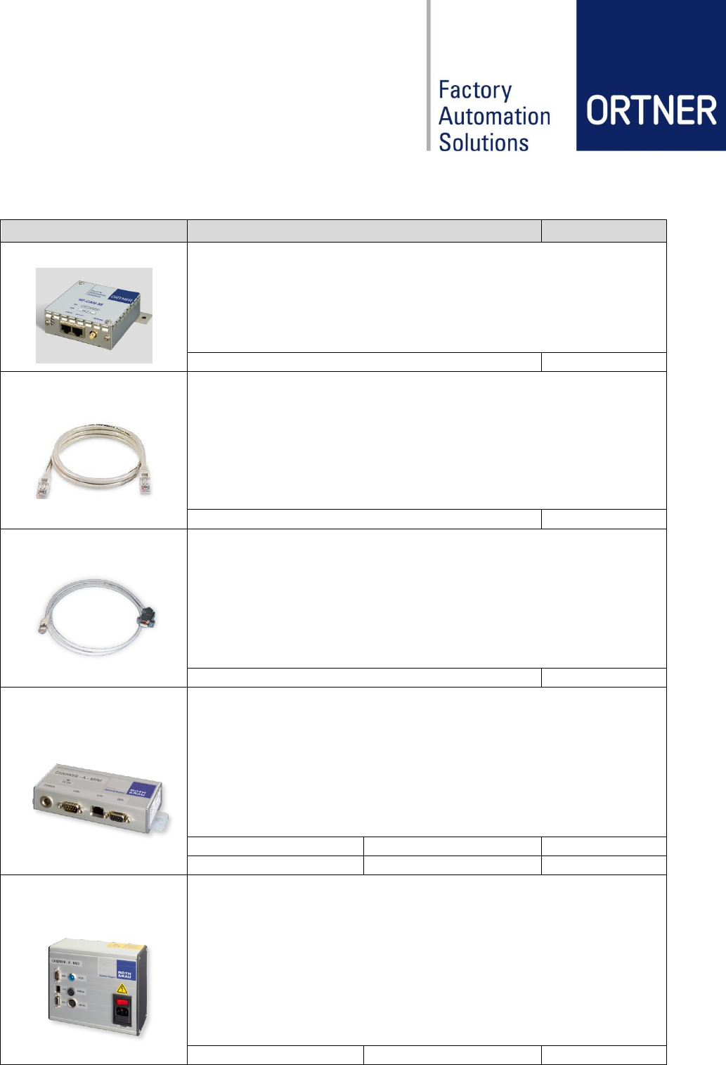
Ortner Test Suite
Comprehensive software tool for testing all Ortner CAN/Serial LF
and HF ID-readers in conjunction with a CAN2Web gateway.
For further information please contact our support:
ortner.support@roth-rau.com
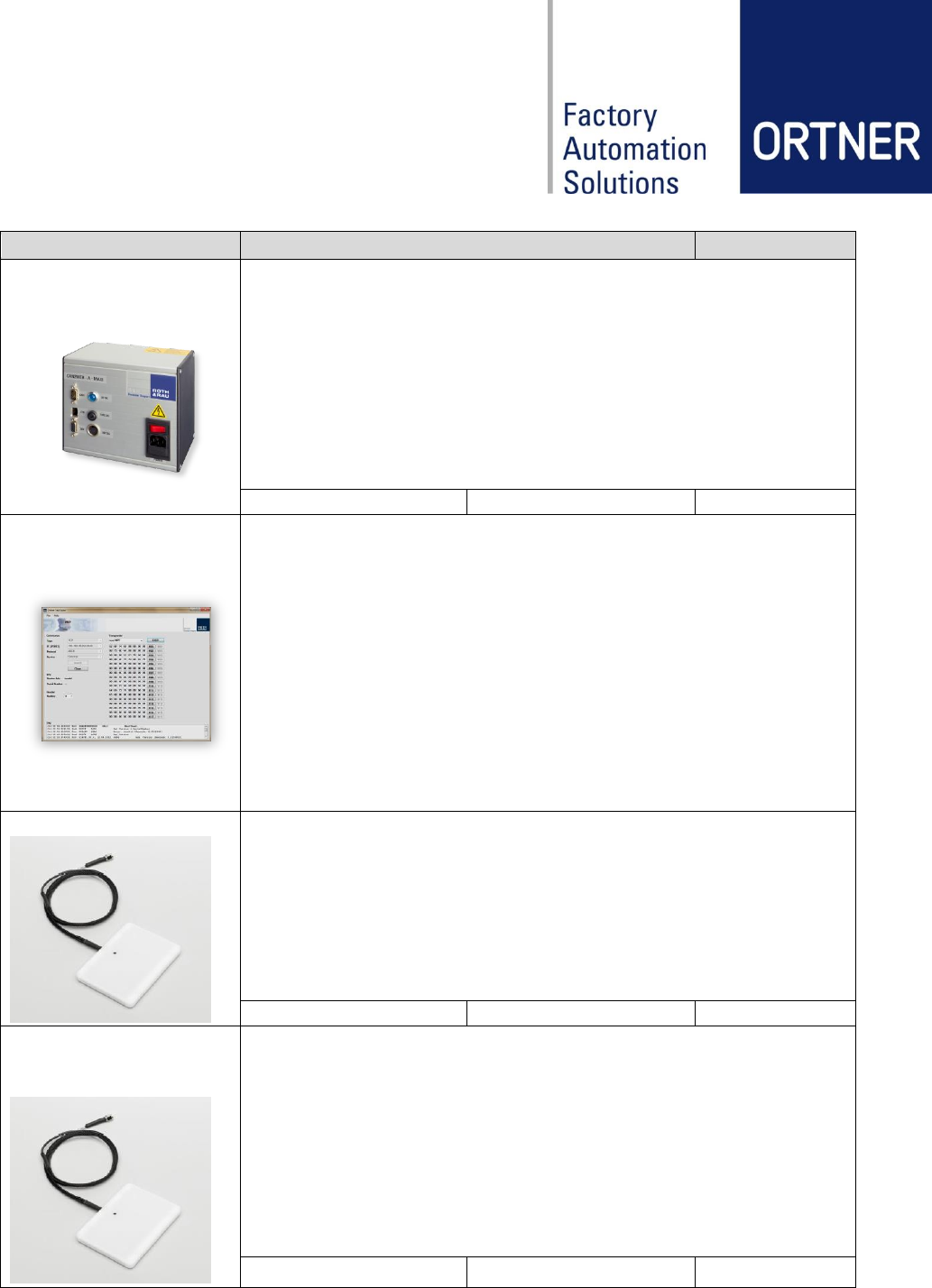
ANT-HF-87 54ES800
External HF Antenna
dimensions: 73 × 96 x 10 mm
connector type: SMA female
available cable lengths: up to 3.6m
ANT-HF-87-54ES0800
cable length 0.8m
000568
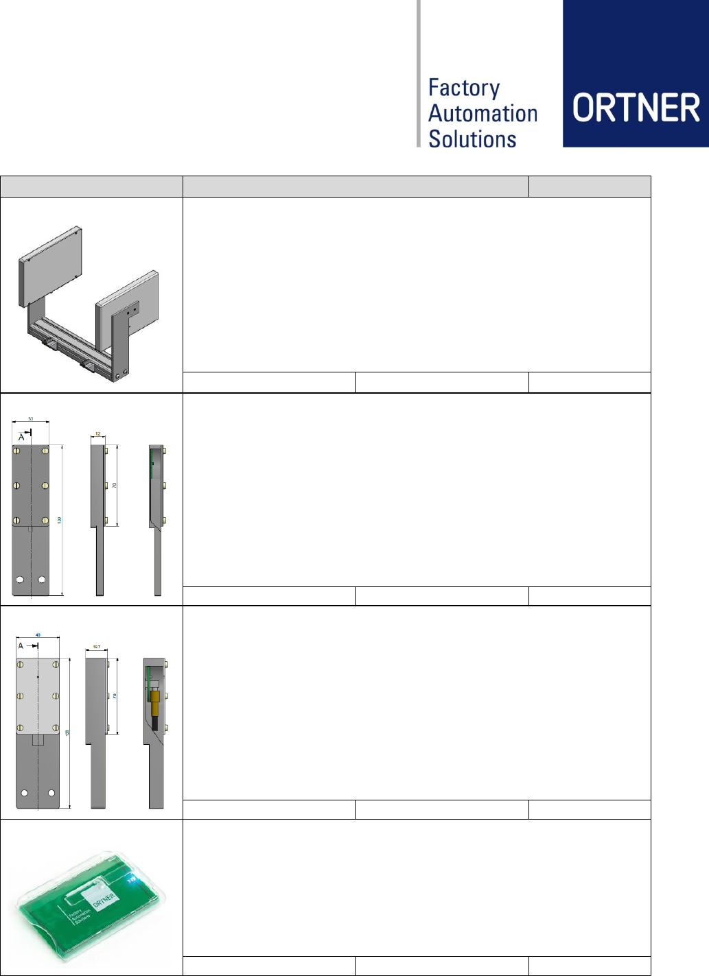
Set ANT-HF-87 54ES
with pluggable high-flex
800 mm cable
External HF Antenna
dimensions: 73 × 96 x 10 mm
connector type: SMA female/ SMA male
case material: ABS, black
available cable lengths: up to 3.6m
Set ANT-HF-87-54ES
cable length 0.8m
000871
Revision: 03 HF-CAN-M User Manual Page 27 of 30
Component
Description
Order Codes
ANTD-HF-140-220E
External HF Antenna
dimensions: 226 × 156 x 20 mm
connector type: SMA female
case material: PP
available cable lengths: up to 3.6m
ANTD-HF-140-220E
cable length 2.2m
000803
ANT-HF-BOS-25ES300
External HF Antenna
dimensions: 32 × 130 x 12 mm
connector type: SMA female
case material: PP wite
available cable lengths: up to 3.6m
ANT-HF-BOS-25ES300
cable length 0.3m
00036-BOS300
ANT-HF-BOS-33ES300
External HF Antenna
dimensions: 40 × 138 x 19.7 mm
connector type: SMA female
case material: PP wite
available cable lengths: up to 3.6m
ANT-HF-BOS-33ES300
cable length 0.3m
000883
HF-Detector-C V1.0
HF Detector
dimensions: 85 × 33 x 1 mm
available with transparent card holder
HF-Detector-C V1.0
000867
* For custom configuration requests please contact us at: ortner.sales@roth-rau.com
Revision: 03 HF-CAN-M User Manual Page 28 of 30
13 Appendix
13.1 Europe CE-Conformity

Revision: 03 HF-CAN-M User Manual Page 29 of 30
13.2 Glossary
ASCII
American Standard Code of Information Inter-exchange
CAN
Controller Area Network
RF
Radio Frequency
RFID
Radio Frequency IDentification
LF / HF
Low / High Frequency
HDX
Half DupleX
ISP
In-Circuit Programmer
FSK
Frequency Shift Keying
MPT / SPT
Multi / Single Page Transponder
RO / RW
Read Only / Read and Write
SAMPT
Selective Addressable Multi Page Transponder
ABS
Acrylonitrile Butadiene Styrene (plastic material)
POM
Polyoxymethylen (plastic material)
SMPS
Switched Mode Power Supply
MES
Manufacturing Execution System
SEMI
Semiconductor Equipment and Materials International
SECS
SEMI Equipment Communication Standard
MTBF
Mean Time Between Failures
MCBF
Mean Cycles Between Failures
TIRIS
Texas Instruments Registration and Identification System (RFID Standard)
13.3 Related documents
UMA_CAN2Web-Advanced_Rev12_Eng
The documents apply in their respective current version.