Fabmatics LF-134-CAN RFID read/write device works in the lower frequency range (134.2 kHz). The integrated CAN bus interface enables simple networking between multiple devices. User Manual LF CAN M UserMan
Roth & Rau - Ortner GmbH RFID read/write device works in the lower frequency range (134.2 kHz). The integrated CAN bus interface enables simple networking between multiple devices. LF CAN M UserMan
LF-CAN-M UserMan
www.rr-ortner.com
This document contains sensitive information and has been provided by Roth & Rau - Ortner GmbH. No part of this document
may be copied, reproduced, published or distributed to third parties without the written consent of Roth & Rau - Ortner GmbH.
Roth & Rau - Ortner GmbH reserves the right to update the information contained in this document without prior notice or con-
sent. Please contact the author of this document to ensure that you have the latest, updated version.
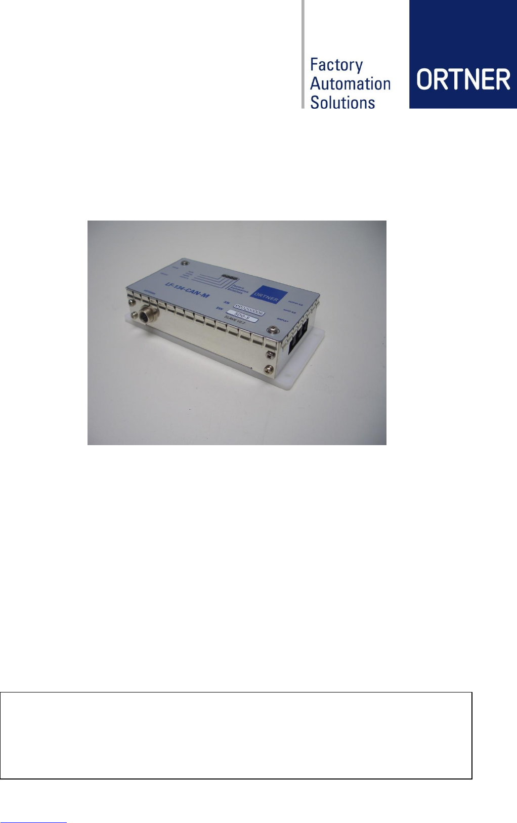
LF-134-CAN-M
Low Frequency RFID Reader
User Manual
Revision: 09
Date created: 25.08.2015
Revision: 09 LF-134-CAN-M Low Frequency RFID Reader User Manual page 2 of 34
Revision table
#
Date
Revision
Description
Name
01
2012/07/12
01
Split LF-134-CAN Rev13, new Layout
CGU
02
2012/07/12
02
Update Antenna information
CGU
03
2012/07/13
03
Update drawings and schematics
CGU
04
2012/07/13
04
Update technical data
CGU
05
2012/07/16
05
Added CE-Declaration
CGU
06
2012/07/16
06
Update technical data and drawings
CGU
07
2012/08/01
07
Update available product revisions
CGU
08
2015/03/19
08
Content update for V3.1, new layout
NEL
09
2015/08/25
09
Add Operational description (chapter 2.2)
NEL

Revision: 09 LF-134-CAN-M Low Frequency RFID Reader User Manual page 3 of 34
Contents
1 General information .........................................................................................................5
2 Product overview .............................................................................................................6
2.1 General function ...................................................................................................6
2.2 Operational description ........................................................................................7
2.3 Product Revision ..................................................................................................8
3 Safety instructions ...........................................................................................................9
3.1 Description ...........................................................................................................9
3.2 General safety instructions .................................................................................10
3.3 ESD Instructions ................................................................................................11
3.4 Intended Use ......................................................................................................11
3.5 Qualifications of the operating and maintenance personnel................................12
4 Compliances .................................................................................................................13
4.1 USA Federal Communications Commission (FCC) ............................................13
4.2 Europe CE-Conformity .......................................................................................13
5 Construction Design ......................................................................................................14
5.1 General Layout ...................................................................................................14
5.2 Product Information Label ..................................................................................14
5.3 Engineer Drawing ...............................................................................................15
6 Hardware Design...........................................................................................................16
6.1 Technical Data ...................................................................................................16
6.2 Operation LED signals (Indicator light) ...............................................................17
6.3 Connector Assignments .....................................................................................17
6.4 External Antenna specification ...........................................................................18
6.5 Reading and writing ranges ................................................................................18
7 Hardware Configuration.................................................................................................20
7.1 CAN-Bus Address Configuration ........................................................................20
7.2 Adjustment of reading range ..............................................................................21
8 Installation .....................................................................................................................22
8.1 General ..............................................................................................................22
8.2 Connection Layout for CAN-BUS / Power (CAN2Web-A-MINI) ..........................22
8.3 Connection Layout for CAN-BUS / Power (CAN2Web-A-MAXI) .........................23
8.4 Installation guide for RFID ferrite core antennas .................................................24
9 Software Configuration ..................................................................................................25
9.1 Content global.cfg at CAN2Web Advanced ........................................................25
9.2 HF relevant settings in global.cfg at CAN2Web Advanced .................................25

Revision: 09 LF-134-CAN-M Low Frequency RFID Reader User Manual page 4 of 34
10 Operation ......................................................................................................................26
10.1 Start-up procedure .............................................................................................26
10.2 During operation .................................................................................................26
10.3 Shutdown ...........................................................................................................26
11 Maintenance, repairs, troubleshooting ...........................................................................27
11.1 Maintenance.......................................................................................................27
11.2 Repairs...............................................................................................................27
11.3 Error Handling ....................................................................................................27
12 Service information ........................................................................................................28
12.1 Contact and support ...........................................................................................28
12.2 Return Material Authorization .............................................................................28
12.3 Warranty ............................................................................................................29
12.4 Disposal .............................................................................................................29
12.5 Accessories ........................................................................................................29
13 Attachments ..................................................................................................................32
13.1 Declaration of conformity LF-134-CAN-M V3.1 ...................................................32
13.2 Glossary .............................................................................................................33
13.3 Related documents ............................................................................................33
Revision: 09 LF-134-CAN-M Low Frequency RFID Reader User Manual page 5 of 34
1 General information
The present instruction manual is the original instruction manual for the product LF-134-CAN-M
of Roth & Rau - Ortner GmbH.
The declaration of conformity is contained in the appendix of the instruction manual.
The instruction manual is intended to enable the operator to safely operate the system as in-
tended and warn them of foreseeable misuse. The manual is intended for the operating compa-
ny´s specialized staff.
This instruction manual must be kept for reference purposes!
Warning
Retain this manual for future reference! The instruction manual must be accessible
to operators and maintenance personnel at all times during installation, operation
and troubleshooting!
A copy of the instruction manual must be kept in a suitable and accessible place.
The explanation of the hazard pictograms is contained in chapter 3.1.
Revision: 09 LF-134-CAN-M Low Frequency RFID Reader User Manual page 6 of 34
2 Product overview
2.1 General function
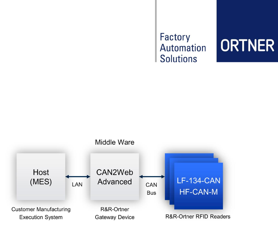
The LF-134-CAN-M reader is designed for operate in reader-networks based on CAN bus. For
connecting the reader network to a Host system (MES), a Roth & Rau - Ortner CAN2Web Mid-
dleware is necessary.
The LF-134-CAN-M reader is an RFID module which supports 134.2 kHz half duplex tran-
sponders. The device works with 64bit “read-only” and 80 bit “read-write” transponder types and
with 1360 bit“ read-write” multipage transponders.
The module contains a CAN uplink for establish the connection to the CAN-Bus controller and a
downlink for extending the ID Reader network.
Features:
- CAN interface (Uplink and Downlink)
- Reads and writes RO/RW/MPT types transponders
- Powerful and efficient output stage

Revision: 09 LF-134-CAN-M Low Frequency RFID Reader User Manual page 7 of 34
2.2 Operational description
2.2.1 How the device operates?
The LF-134-CAN device reads FDX transponder on request from a master device
(CAN2Web box).
2.2.2 How is the device modulated?
The reader sends out a charge burst of 134KHz in 50msec length. After the burst, the
transponder answers back FSK signal shifting between 124KHz and 134KHz.
The modulation follows ISO18000-2 FDX mode.
2.2.3 Short description of the device
RFID reader for ISO18000-2 FDX transponder (mainly TI TIRIS transponder)
2.2.4 Pulse rate
At fastest 100msec cycle. 50msec charge, 20msec listen, 30msec pause.
2.2.5 Signal type
FSK signal from transponder
ASK signal from reader
2.2.6 Information being sent
8bytes of data + CRC
Revision: 09 LF-134-CAN-M Low Frequency RFID Reader User Manual page 8 of 34
2.3 Product Revision
Product Code
Product Revision
Hardware
Version
Available Software Version
LF-134-CAN-M
3.1
1.3
Slave, Master, DMS
The product code consists of following information:
LF – 134 – CAN – M – V3.1
Frequency Spectrum Interface Product Revision
Frequency Case Version
The available software versions are:
Software
Description
Slave-V27
Device will be controlled completely by CAN2Web Box or CAN-
Controller.
SDO Mas-
ter_V4_1_130112
Version for readers with display and IFD transponder structure
dms10d
Software for readers with display and DMS transponder structure
(reticle), version without external interface (IFD)
dms22
Software for readers with display and DMS transponder structure
(reticle), reading by IRG possible, texts in English (SkWs)
Our software code consists of following information:
SLAVE –V27
Software Type Software Version
Note
The product revisions are denoted by revision numbers. The respective revision
numbers of the three components of each product belong to the product revision
numbers: hardware, software, design.
Each product revision number is distinctive and denotes a particular design or a
particular function of the product. Changes in design necessitate a new product
revision number. Changes in the two product components hardware and software
may, but don´t have to result in a new product revision number.
Revision: 09 LF-134-CAN-M Low Frequency RFID Reader User Manual page 9 of 34
3 Safety instructions
This chapter explains general safety guidelines along with an explanation of the symbols. The
user is informed about dangers, residual risks and measures for reducing risks in the chapter
safety regulations.
Additionally, action-related and situational safety instructions have been placed in the corre-
sponding chapter of the instruction manual.
3.1 Description
Danger
This symbol refers to major hazards to life and health for persons. Pay strict atten-
tion to the information provided in these sections and proceed with the utmost
care!
Warning
This symbol refers to hazards to life and health for persons. Pay strict attention to
the information provided in these sections and proceed with the utmost care!
Caution
This symbol warns of minor injury and material damage to the product as well
potentially unsafe use.
Note
Information serves to warn against operating errors and to highlight important
topics and respectively gain a better understanding of the product.
Revision: 09 LF-134-CAN-M Low Frequency RFID Reader User Manual page 10 of 34
3.2 General safety instructions
The LF-134-CAN-M is considered state-of-the-art technology and meets the recognized safety
rules and regulations. Nevertheless, dangers may still arise.
The product may only be operated in perfect condition and in compliance with the present in-
struction manual.
Warning
You must read and understand all safety and operating instructions before using
the product!
The product may only be operated in perfect technical condition and in compliance
with all chapters of the instruction manual!
The following safety information is understood to be in addition to the existing accident preven-
tion regulations and laws. Existing safety prevention measures and laws must be followed at all
costs.
Danger
All antenna resonant circuit components carry high voltage!
The installer is responsible for installing the device to comply with FCC require-
ments of human exposure to radio frequency.
Warning
To prevent fire, shock hazard, or annoying interference, use recommended acces-
sories only.
Warning
When removing the housing lid, note that the housing lid is connected to the case
with a cable. Remove the lid carefully to prevent damage – do not pull it! Do not
operate the device when the housing lid is removed!
Warning
Never locate the antenna so that it is very close to or touching parts of the body
while transmitting.
Caution
Do NOT operate this device without a proper antenna attached. Proper antennas
are antennas supplied by the manufacturer and listed in section spare parts.
Revision: 09 LF-134-CAN-M Low Frequency RFID Reader User Manual page 11 of 34
Only use accessories, extensions and connection cables which have been approved for use by
Roth & Rau - Ortner.
The Roth & Rau - Ortner sales team is available to answer questions about approved accesso-
ries.
Note
When removing a cable, only pull on the connector and not the cable itself. Make
sure that the connectors are properly fixed to avoid bending the pins. Ensure that
the pins are in the correct position when connecting a cable.
In the event of mechanical damage to the product, the LF-134-CAN-M must be disconnected
from the power supply.
3.3 ESD Instructions
Static electricity can harm electronic components inside the device. All persons who install or
maintain the device must be trained in ESD protection. ESD protection measures must be ob-
served when opening the device.
Before removing or inserting components, disconnect the power supply.
To prevent electrostatic damage, static electricity must be discharged from the body and tools
before touching components inside the device.
Touch electro-sensitive components carefully at their edges only.
3.4 Intended Use
This product was developed for reading and writing the TIRIS® transponder only. Any other use
of this device would constitute abuse.
Proper antennas for reading and writing are antennas supplied by the manufacturer. Never lo-
cate the reader with antenna so that it is very close to or touching parts of the body while trans-
mitting.
This product is designed to be mounted and operated in an industrial environment as a built-in-
device only. It is not designed to be used as a stand-alone or a portable device in a non-
industrial environment, such as a household, automotive or open-air environment.
The device may be used no closer than 20cm to the human body.
Any use outside of the general conditions described in the existing instruction manual consti-
tutes improper use.
Revision: 09 LF-134-CAN-M Low Frequency RFID Reader User Manual page 12 of 34
3.5 Qualifications of the operating and maintenance personnel
The intended group of users of the product is the operating personnel (system operators) and
the maintenance personnel.
It is assumed that all users have been acquainted with the function and dangers of the overall
system before beginning work.
All operators, service personnel, fitters and maintenance personnel should be instructed on at
least the following topics:
- Basic functions of the system in which the HF-CAN-M readers are installed
(operator)
- Manual (operator)
- Software for configuration (set-up and maintenance staff)
The operating instructions were designed for trained personnel. The device may only be in-
stalled and serviced by Roth & Rau - Ortner or personnel trained for this purpose.
Warning
Interventions and troubleshooting which are not described in this instruction man-
ual may only be carried out by Roth & Rau - Ortner.
Warning
The commonly accepted regulations for work safety must be adhered to!
Caution
Operation and troubleshooting may only be carried out by specially trained per-
sonnel.
The prerequisite is that the operating instructions have been read and understood.
Should you be unsure as to which qualifications must be present, then contact
Roth & Rau - Ortner!
Revision: 09 LF-134-CAN-M Low Frequency RFID Reader User Manual page 13 of 34
4 Compliances
4.1 USA Federal Communications Commission (FCC)
LF-134-CAN-M is a class A digital device. It is a digital device that is marketed for use in a
commercial, industrial or business environment, exclusive of a device which is marketed for use
by the general public or is intended to be used in the home.
4.1.1 Compliance
The product complies with FCC Subpart C – Intentional Radiators §15.201 and with Subpart J –
Equipment Authorization Procedures § 2.209, when used for its intended purpose. All emissions
are at least 40 dB below the limits in § 15.209 and are verified pursuant to the procedures in
FCC Subpart J of part 2. These limits are designed to provide reasonable protection against
harmful interference when the equipment is operated in a commercial environment. This equip-
ment generates, uses, and can radiate radio frequency energy and, if not installed and used in
accordance with the instruction manual, may cause harmful interference to radio communica-
tions. Operation of this equipment in a residential area is likely to cause harmful interference in
which case the user will be required to correct the interference at his/her own expense.
4.1.2 Antenna Requirements
The antenna is removable and does not employ a unique connector; however, the device is
professionally installed and maintained. Therefore, the described reader LF-134-CAN-M com-
plies with FCC15.203.
4.1.3 Labeling Requirements
The described reader LF-134-CAN-M is not large enough to accommodate a label with the
standard FCC compliance statement. It is therefore provided here as follows:
This device complies with Part 15 of the FCC Rules. Operation is subject to the following two
conditions: (1) this device may not cause harmful interference, and (2) this device must accept
any interference received, including interference that may cause undesired.
For further information please see chapter 5.2.
4.2 Europe CE-Conformity
The EC-declaration of conformity is included in appendix in chapter 13.1.
Caution
Changes or modifications not expressly approved by the party responsible for
compliance may void the user’s authority to operate the equipment.
Revision: 09 LF-134-CAN-M Low Frequency RFID Reader User Manual page 14 of 34
5 Construction Design
This chapter specifies all the essential hardware components. Block diagrams serve to present
the product´s essential hardware components. The table on technical data lists and numbers all
known technical details which are necessary for distinctively labeling the product.
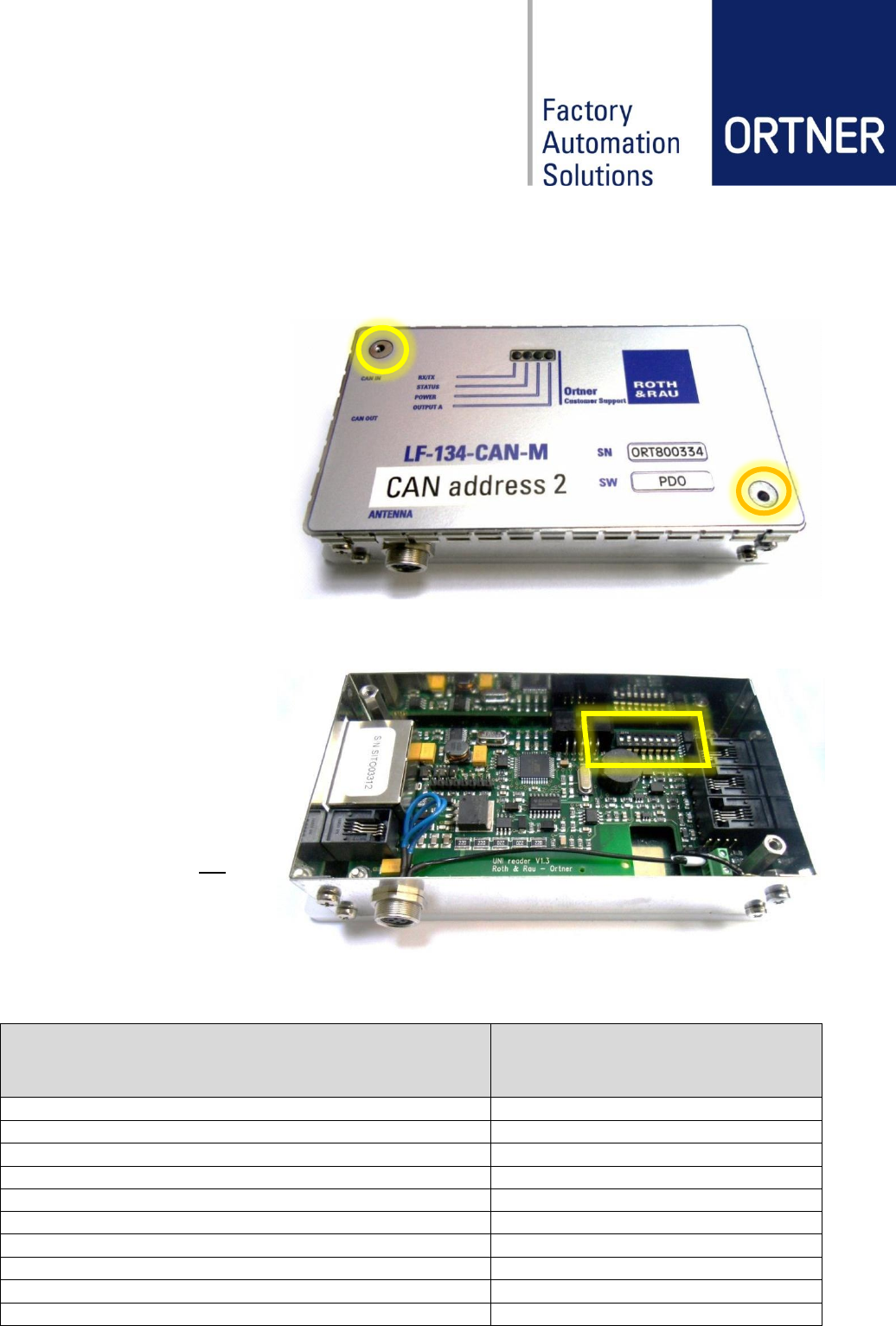
5.1 General Layout
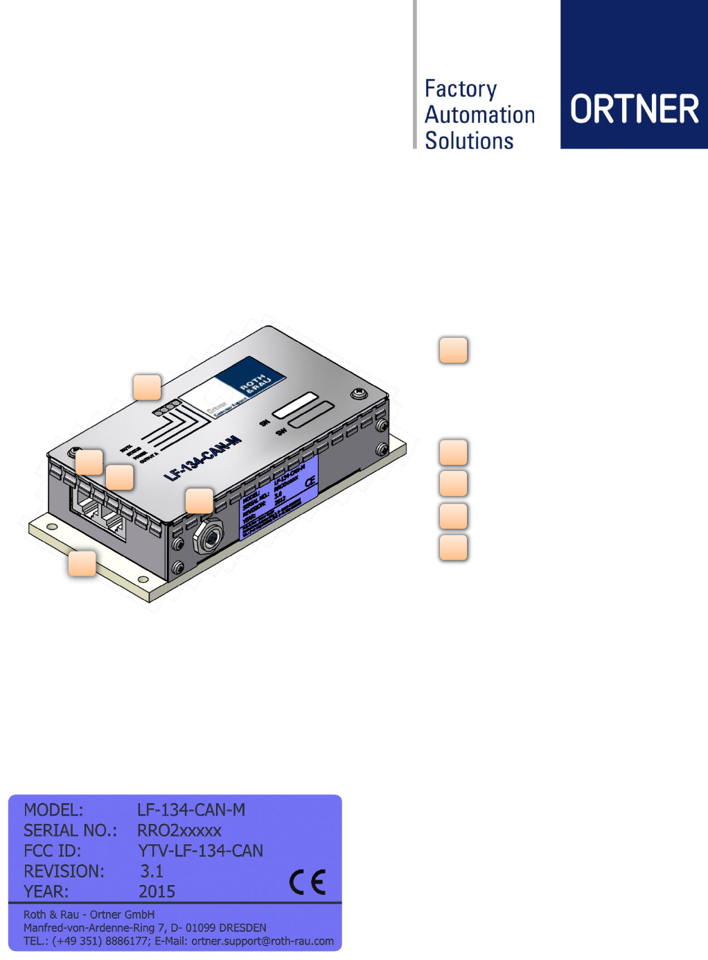
5.2 Product Information Label
The product information label is located on the back side (see also engineer drawing in chapter
5.3) and contains the product name (Model), product revision, serial number and year of pro-
duction. Serial number is RRO9xxxxx starting with 2012. Before 2012 it was ORT15xxxx. Fur-
thermore the FCC number YTV-LF-134-CAN is listed and the CE-mark.
The dimension of label is 21,5mm x 46 mm.
2
4
3
1
5
Operation LEDs
- RX/TX
- Status
- Power
- Output A
CAN IN
CAN OUT
ANTENNA
Base Plate
1
2
3
4
5
Revision: 09 LF-134-CAN-M Low Frequency RFID Reader User Manual page 15 of 34
5.3 Engineer Drawing
Revision: 09 LF-134-CAN-M Low Frequency RFID Reader User Manual page 16 of 34
6 Hardware Design
6.1 Technical Data
Designation
LF-134-CAN-M
Dimensions (w-h-d)
without Base plate:
130 x 80 x 30mm
with Base plate:
150 x 80 x 35mm
Weight
273g (with Base plate)
Case Material
Case: Tin plate Base Plate: POM
Operating temperature
0°C to +50°C
Storage temperature
-25°C to +50°C
Voltage power supply
(typical)
24V +/- 3%
Power consumption
5.0W reading / 1.3W stand-by (typical)
Antenna
ferrite coil and air coil
RFID frequency
134.2kHz
Readable transponder types
134.2kHz HDX/FSK, MPT, SAMPT, RW, RO (e.g. TI 32
mm Glass Transponder RI-TRP-DR2B)
MTBF
≥ 40,000h
MCBF
≥ 1,000,000 reading cycles
Reading time one page
Average 110msec
Speed of CAN-Bus
adjustable up to 1MBit/sec, typical 100kBit/sec
Max. CAN cable length
100 m
Connectors
CAN In (RJ45) CAN-Bus / power in
CAN Out (RJ45) CAN-Bus / power out
Antenna (RJ10) external antenna
Output A,B (RJ10) 2 digital channels out
Input A,B (RJ10) 2 digital channels in
Display (RJ10) powered serial display link
Revision: 09 LF-134-CAN-M Low Frequency RFID Reader User Manual page 17 of 34
6.2 Operation LED signals (Indicator light)
In the table below the meaning of each status lights on the device top cover is describe
in detail.
6.3 Connector Assignments
6.3.1 Pin configuration of CAN IN/OUT connectors
Both CAN connectors (CAN-IN and CAN-OUT) are RJ45, 8 poles and have the following pin
configuration:
PIN number
Description
1
CAN_H
2
CAN_L
3
CAN_GND
4
CAN_V+ (12-30VDC)
5
n.c.
6
CAN_SHIELD
7
CAN_GND
8
CAN_V+ (12-30VDC)
6.3.2 Pin configuration of Antenna connector
The antenna connector is 4P4C (RJ10), 4 poles and has the following pin configuration:
PIN number
Description
1
antenna OUT
2
antenna OUT
3
antenna IN
4
antenna IN
LED name
Color
Description
RX/TX
Yellow
ON – CAN Data transfer active
Status
Red
ON – Communication with CAN-Master established
Power
Green
ON – 24V Power OK
Output A
Yellow
Optional
Revision: 09 LF-134-CAN-M Low Frequency RFID Reader User Manual page 18 of 34
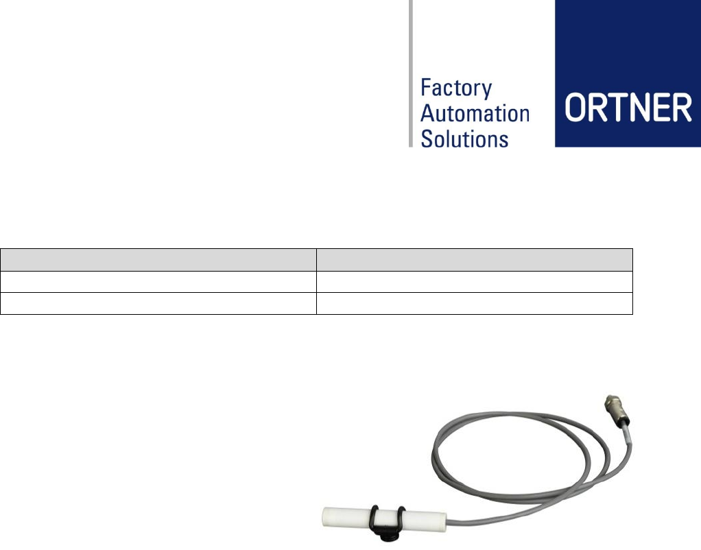
6.4 External Antenna specification
The external antenna will be connected to the antenna Binder Plug Socket. Antenna wire thick-
ness should be at least 0.5 mm but it can be an air coil or ferrite coil.
Antenna specification
Frequency
134,2 kHz
Inductivity
48 µH +/- 3%
Our most common used antenna design is a 65mm ferrite coil. It can provide reading ranges
for at least 200mm with a 23mm glass tube read-only transponder.
This is just an example Antenna-Design.
For detailed information about all available
Antenna types and corresponding reading
ranges, please refer to the separate
Datasheets like:
- ANT04-35EB
- ANT08-65EBF (High Flex Cable)
- ANT10-100EBF (High Flex Cable)
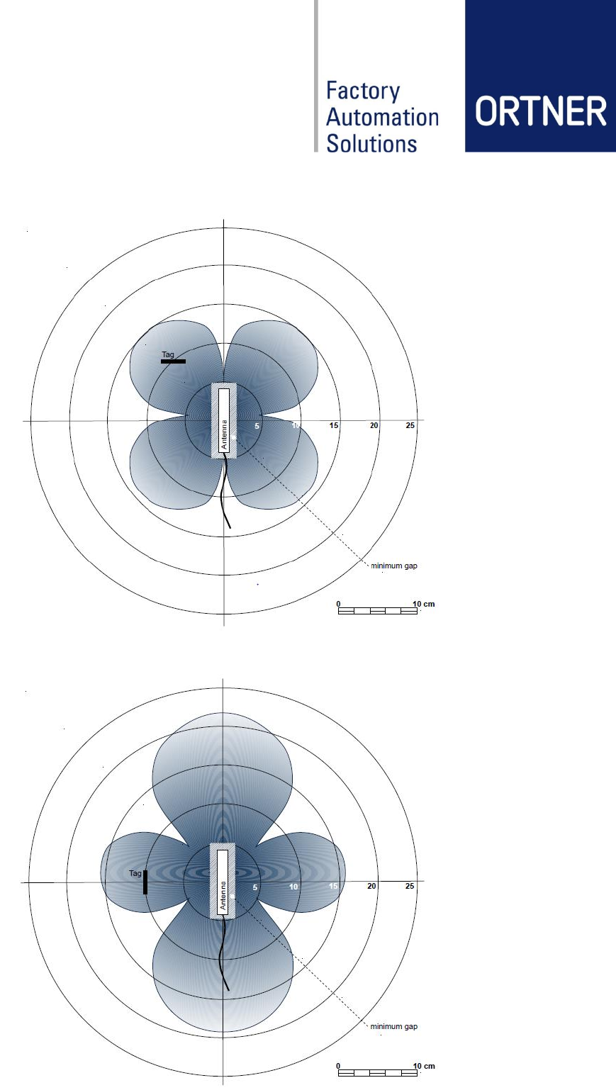
6.5 Reading and writing ranges
The following antenna range figures are measures by using our most common antenna type
ANT08-65EB. This is just an example to show how the antenna ranges are correlating with dif-
ferent transponder (tag) positions.
Detailed information about all available antenna types and their corresponding ranges, please
refer to chapter 12.5 and the separate antenna data sheets like:
- ANT04-35EB
- ANT08-65EBF (High Flex Cable)
- ANT10-100EBF (High Flex Cable)
The following reading ranges are measured with best conditions; in real environment the ranges
will be much smaller due to disturbing material, like metal or other electro-magnetically fields
near the antenna location. Please improve the condition before finally decision of the antenna
location.
Writing ranges under same conditions are approx. 60% of the below described reading ranges.
Close to the antenna tag reading and writing will also be not possible, so prevent a tag place-
ment very close to the antenna, as a guide value prevent a distance below 10 mm.
Revision: 09 LF-134-CAN-M Low Frequency RFID Reader User Manual page 19 of 34
6.5.1 Reading range – orthogonal alignment (ANT08-65EB)
6.5.2 Reading range – parallel alignment (ANT-08-65EB)
Output power: 100%
Alignment: Antenna/Tag parallel (50 mm/div)
Output power: 100%
Alignment: Antenna/Tag parallel (50 mm/div)
Revision: 09 LF-134-CAN-M Low Frequency RFID Reader User Manual page 20 of 34
7 Hardware Configuration
7.1 CAN-Bus Address Configuration
To change the CAN-Address
it’s necessary to open the de-
vice by removing two screws
on the top cover.
ATTETION:
Make sure the device is pow-
ered off before remove the top
cover!
The CAN-ID will be read on every power up cycle. That means if the CAN-ID became changed
during power on, the device must be restarted by power off and on again to be able to use the
new ID.
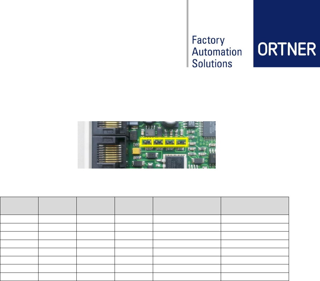
The ID can set from 1 to 127
in binary code by using the
DIP-Switches No.1-7.
The DIP-Switch No.8 has to
be off at all time.
The CAN ID-block uses an
11 Bit identifier and not the
extended 29 Bit identifier.
Following table shows some configuration examples of how to set the CAN-ID (Reader Ad-
dress).
DIP-Switches
1 2 3 4 5 6 7 8
CAN-ID (Reader Address)
1 0 0 0 0 0 0 0
1
0 1 0 0 0 0 0 0
2
1 1 0 0 0 0 0 0
3
0 0 1 0 0 0 0 0
4
1 0 1 0 0 0 0 0
5
0 1 1 0 0 0 0 0
6
1 1 1 0 0 0 0 0
7
0 0 0 1 0 0 0 0
8
… 0
…
1 1 1 1 1 1 1 0
127
Revision: 09 LF-134-CAN-M Low Frequency RFID Reader User Manual page 21 of 34
7.2 Adjustment of reading range
Jumper J1 – J4 settings for RF power level on LF-134-CAN-M. This setting defines the power
level for the transmitting amplifier. All values are calculated values and might be differ a bit.
J1
J2
J3
J4
RF supply Voltage
(approx.)
Read distance
(approx.)
OFF
OFF
OFF
OFF
23,75 V
100%
OFF
OFF
OFF
ON
14,75 V
85%
ON
OFF
OFF
OFF
12,50 V
81%
ON
OFF
OFF
ON
9,70 V
74%
ON
ON
OFF
OFF
8,75 V
71%
ON
ON
OFF
ON
7,40 V
67%
ON
ON
ON
OFF
6,87 V
66%
ON
ON
ON
ON
6,07 V
63%
J1
J2
J3
J4
Revision: 09 LF-134-CAN-M Low Frequency RFID Reader User Manual page 22 of 34
8 Installation
8.1 General
All ID-Readers will be connected through CAN-Bus to the CAN2Web-Advanced box.
Depending on your CAN2Web Version (MINI/MIDI/MAXI) a maximum number of 8 (MINI) or 50
(MIDI/MAXI) readers can be connected to one box. The maximum CAN-cable length is 100 m.
If more than 10 Reader Devices (MIDI/MAXI) needs to be connected, a special CAN/Power split
cable is necessary. Please refer to the separate data sheet of CAN-POWER-INJECTOR and
the user manual of CAN2Web Advanced.
NOTE: Before power on the ID-Reader Network, it’s necessary to make sure the CAN-ID (Ad-
dress) for each ID-Reader device is setup correctly like in the following figures. The CAN2Web-
Gateways are preconfigured with CAN-ID 0 – there is no need for change. The readers usually
will be delivered with preconfigured CAN-IDs depending on customer requests. In case of
changes needs to be done, it is shown how to change the CAN-IDs in Section 0.
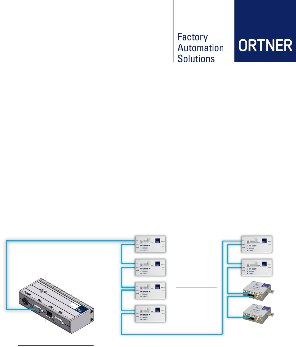
8.2 Connection Layout for CAN-BUS / Power (CAN2Web-A-MINI)
This two example figures are showing how the ID-Reader Network can be built.
Up to 8 CAN RFID-Readers can be connected, depending on cable length of CAN-Bus.
CAN Bus / Power
CAN Bus / Power
CAN2Web Advanced MINI
Up to 4 CAN RFID-
e.g.
LF-134-CAN/-M
HF-CAN-M
RFID Reader
CAN Master
ID 0
CAN ID 2
CAN ID 1
CAN ID 3
CAN ID 4
CAN ID 5
CAN ID 6
CAN ID 7
CAN ID 8
Revision: 09 LF-134-CAN-M Low Frequency RFID Reader User Manual page 23 of 34
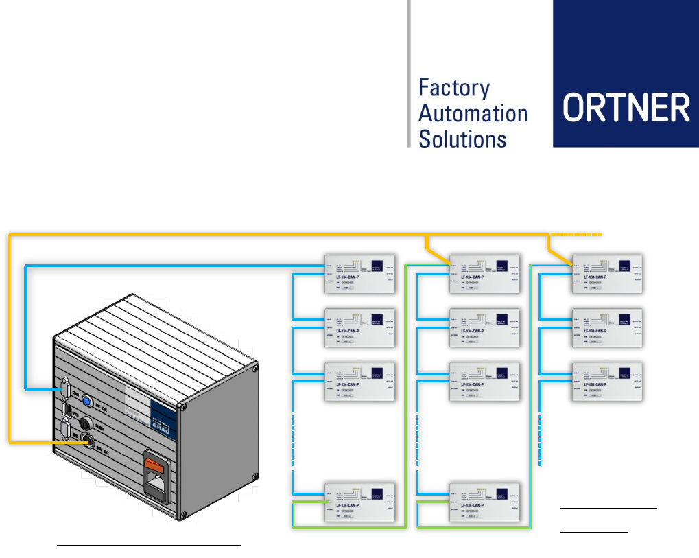
8.3 Connection Layout for CAN-BUS / Power (CAN2Web-A-MAXI)
Up to 50 CAN RFID-Readers can be connected, depending on cable length of CAN-Bus.
CAN Bus / Power
CAN Bus / Power
CAN2Web Advanced MAXI
Auxiliary Power
max. 10 devices
per section!
max. 10 devices
per section!
max. 10 devices
per section!
min. 5 power sections under full expansion!
e.g.
LF-134-CAN/-M
HF-CAN-M
RFID Reader
CAN ID 1
CAN ID 2
CAN ID 3
CAN ID 10
CAN ID 11
CAN ID 12
CAN ID 13
CAN ID 20
CAN ID 21
CAN ID 22
CAN ID 23
CAN Master
ID 0
CAN Bus
CAN Bus
Revision: 09 LF-134-CAN-M Low Frequency RFID Reader User Manual page 24 of 34
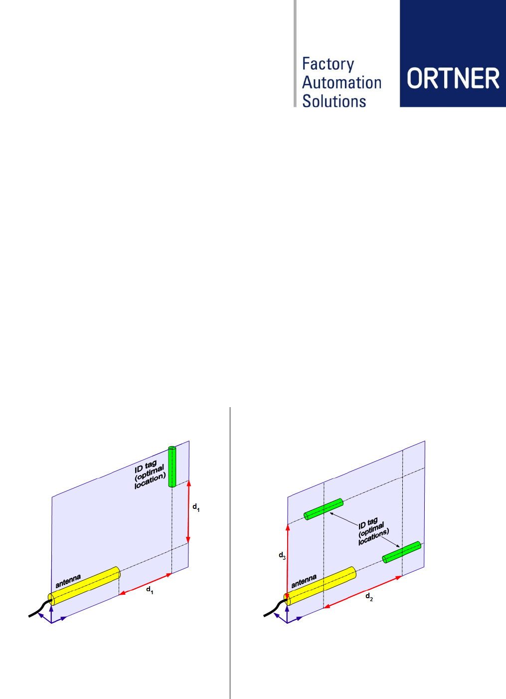
8.4 Installation guide for RFID ferrite core antennas
This guide shall show you the best way to install RFID antennas to your devices to achieve safe
reading results. It considers two possible orientations between antenna and ID tag:
1. Antenna is orthogonal to the ID tag.
2. Antenna is parallel to the ID tag.
General information:
- Don’t attach RFID antennas directly to metal surfaces and avoid ferromagnetic materi-
als! Leave a gap of at least 5mm and use plastic mountings and screws for fixing the an-
tenna.
- Don’t install antennas, cables or reading devices close to electromagnetic radiating de-
vices such as switched-mode power supplies!
- Only use shielded cables and try not to loop the remains!
- Try to align antenna and ID tag in one layer. (see case explanations)
- Maximum distances are given for best surrounding conditions. In reality the max-
imum distances may be lower due to other electromagnetic interferences! So, try
to keep the distance between antenna and ID tag as low as possible.
Case 1: Antenna orthogonal to ID tag
Case 2: Antenna parallel to ID tag
Antenna type ANT08-65E
Antenna type ANT08-65E
d1 min = 10 mm
d1 max = 80
mm
d2 min = 10 mm
d3 min = 10 mm
d2 max = 200 mm
d3 max = 100 mm
Considering the suggested alignment between antenna and ID tag should perform best results.
If you still encounter problems or for further information please contact our Customer Support:
ortner.support@roth-rau.com
Revision: 09 LF-134-CAN-M Low Frequency RFID Reader User Manual page 25 of 34
9 Software Configuration
This chapter serves to familiarize the user with software-related configuration.
The exact software configuration depends on the software or interface package which has been
ordered. Please refer to interface documentation for details.
9.1 Content global.cfg at CAN2Web Advanced
//set globals for all gateways
offline_time 30
gateway_one_rs232 0
transponder_type 3
max_socket_server 1
accept_tcpip_connection 1
auto_adjustment 1
iso15693_rf_mode 0x2c
// End of global.cfg
9.2 HF relevant settings in global.cfg at CAN2Web Advanced
9.2.1 Parameter transponder_types
Transponder type
Value at global.cfg
Transponder example
LF_SINGLE
0
TI 32 mm Glass Transponder RI-TRP-RR2B
LF_MULTI
1
TI 32 mm Glass Transponder RI-TRP-DR2B
HF_ISO_15693
2
(for HF ISO_15693 transponders)
HF_IFX
3
(for HF transponders using IFX customer mode)
Revision: 09 LF-134-CAN-M Low Frequency RFID Reader User Manual page 26 of 34
10 Operation
10.1 Start-up procedure
Before delivery, the product is factory-tested as part of the quality assurance throughout the
production process.
Start-up of the RFID system with LF-134-CAN-M is carried out by trained personnel (see chap-
ter 3.5). Requirements for the start-up by the customer are:
- The user manual of reader and of used CAN2Web Advanced is available to the
start-up personnel.
- The mains supply is connected.
- The configuration in CAN2Web Advanced has been made.
Via the power switch on the CAN2Web Advanced box, the overall system and all connected
readers are supplied with the supply voltage (24 VDC) and the CAN bus signal.
Note
The system needs approx. 3 seconds to be ready for operation!
10.2 During operation
After completing the configuration and the start-up, the product is in operation.
Switching or control operations are not required during operation.
10.3 Shutdown
The LF-134-CAN-M can be shut down for a longer period of time without any additional risks.
No special maintenance work is necessary during this period.
The decommissioning is performed by connecting off the CAN cable on the LF-134-CAN-M.
Revision: 09 LF-134-CAN-M Low Frequency RFID Reader User Manual page 27 of 34
11 Maintenance, repairs, troubleshooting
11.1 Maintenance
The LF-134-CAN-M was designed so that it is nearly maintenance free.
The surfaces can be cleaned using a lent-free cloth and isopropyl.
Before starting any work on the system, the housing and functional elements must always be
checked for damage and attention paid to noises!
Warning
Interventions in the product and the software configuration may only be carried out
in coordination with Roth & Rau - Ortner or by trained users or specialist compa-
nies.
Note
In particular, changes to the software can lead to malfunctions and operational
problems.
Note
The CAN bus ID´s for the LF-134-CAN-M have been preset and configured ex
works. Changes to the CAN bus ID are only to be made if the corresponding sys-
tem is replaced.
11.2 Repairs
Warning
Repairs may not cause a change in function. The product may not be altered or
manipulated.
The system must be shut off before each repair. The LF-134-CAN-M must be disconnected
from the power supply.
System maintenance and repairs are only to be performed by Roth & Rau - Ortner or specialist
companies.
11.3 Error Handling
In case of serious system disorders please contact the Roth & Rau – Ortner Support:
Phone: +49 351 888 61 77 (only daytime CET)
Fax: +49 351 888 61 20
Mail: ortner.support@roth-rau.com
Revision: 09 LF-134-CAN-M Low Frequency RFID Reader User Manual page 28 of 34
12 Service information
12.1 Contact and support
Please contact the sales team at Roth & Rau - Ortner to order components or spare parts:
Telephone +49 351 88861-0 (during business hours)
Fax +49 351 88861-20
Email ortner.sales@roth-rau.com
Roth & Rau - Ortner offers telephone and e-mail support for all components. This includes sup-
port for operating the components and for integrating the devices into other equipment. The
telephone support is available during regular business hours (8am to 5pm CET, after hours
there is an answering machine).
Please contact our team for help:
Telephone: +49 351 88861-77 (during business hours)
Fax: +49 351 88861-20
Email: ortner.support@roth-rau.com
12.2 Return Material Authorization
Please request an RMA number before returning a defective device to Roth & Rau - Ortner.
This process ensures the return and allows for faster classification of the problem and re-
pair/replacement of the defective device
1. Please contact us by telephone or e-mail to get an RMA form and RMA number.
2. Roth & Rau - Ortner generates an RMA number
3. With the help of the RMA number, the RMA form can be completely filled out.
4. Send the defective unit along with the completed form to:
Roth & Rau - Ortner GmbH
R M A [ Nummer ]
Manfred-von-Ardenne-Ring 7
01099 Dresden
GERMANY
Note
It is imperative that the RMA number is clearly visible on the package. This en-
sures that your order can be processed faster.
Pack the device suitably to avoid damage during transport!
5. Acknowledgement of receipt and processing of the RMA order by Roth & Rau - Ortner.
6. The repaired/replaced device is returned to you
Revision: 09 LF-134-CAN-M Low Frequency RFID Reader User Manual page 29 of 34
12.3 Warranty
The warranty period is 24 months from the delivery of the device (proof by invoice or other doc-
uments).
The warranty includes repairs for all damage to the system which occur within the warranty pe-
riod and are demonstrably the result of material or production defects. The warranty does not
cover any damages which are the result of incorrect connections, improper handling or disre-
garding the technical documentation and the instruction manual.
12.4 Disposal
Within the EU, Roth & Rau - Ortner takes back the devices for disposal. Further information
about returning the device can be obtained from the support of Roth & Rau - Ortner GmbH
If you dispose of the device yourself, please note the legal provisions.
12.5 Accessories
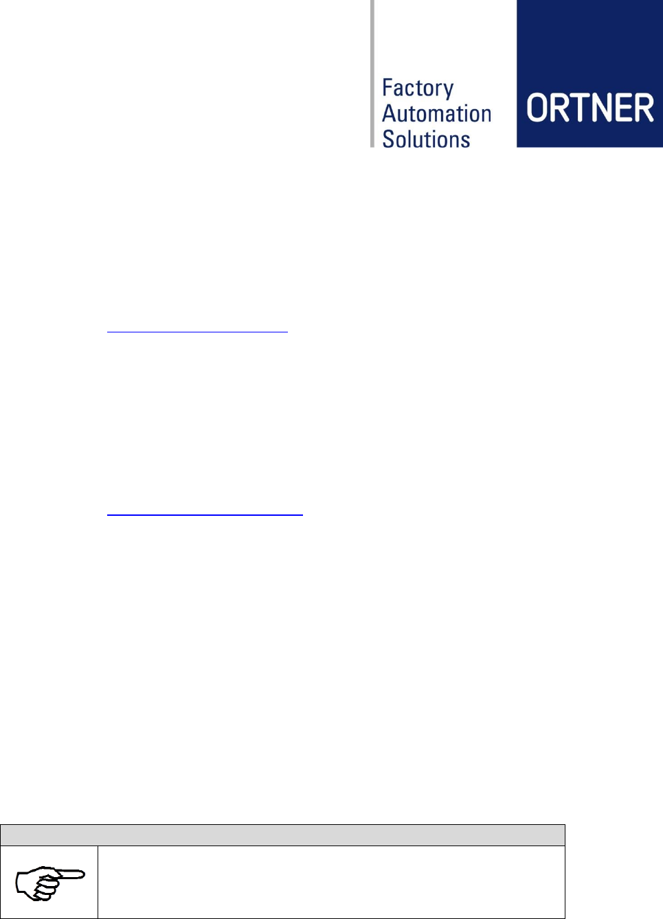
Roth & Rau - Ortner offers the following original accessories for the LF-134-CAN-M.
Component
Description
Order Codes
LF-134-CAN-M
Multifunctional 134 kHz low frequency RFID-reader with tinplate
metal case. Multiple readers can be connected to one CAN2Web-
gateway by RJ45 CAN-bus cable.
LF-134-CAN-M-0-V3.1 - SDO-S
000865
LF-134-CAN-M-0-V3.1 - SDO-M
000864
LF-134-CAN-M-0-V3.1 - PDO
000866
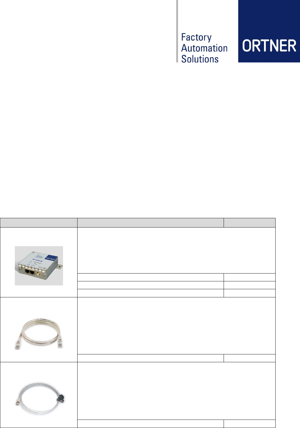
Cable-ETH
CAN-bus cable for direct connection between all variants of Ortner
LF-/HF-RFID-readers. RJ45 to RJ45.
NOTE: The cable cannot be replaced by any Ethernet cable!
cable lengths will be customized
000144
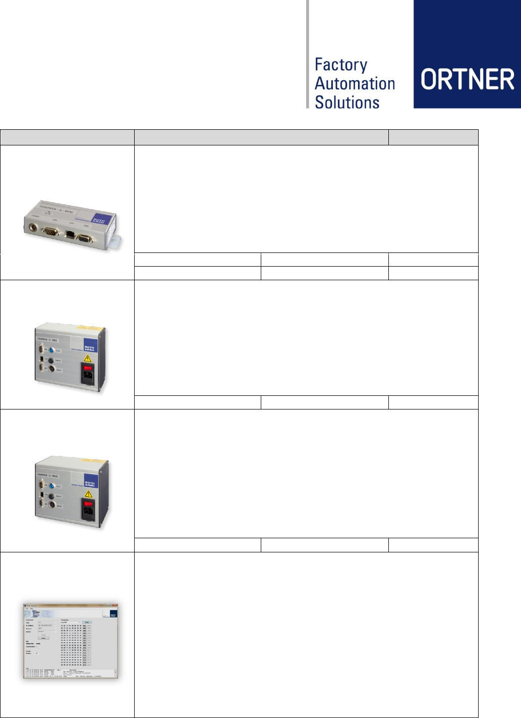
Cable-CAN-SER
CAN-bus cable for connecting all versions of a CAN2Web-gateway
to the first ID-reader in a CAN-bus network.
DE9 to RJ45.
cable length 1.5m
000130
Revision: 09 LF-134-CAN-M Low Frequency RFID Reader User Manual page 30 of 34
Component
Description
Order Codes
CAN2Web Advanced
MINI
Multifunctional CAN-bus to Ethernet gateway device to connect Ort-
ner RFID-readers to a host system. Supplies up to 8 devices.
CAN2Web-A-MINI 64
w/o base plate
000076-64MB
CAN2Web-A-MINI 64
with base plate
000170-64MB
CAN2Web Advanced
MIDI
Multifunctional CAN-bus to Ethernet gateway device to connect Ort-
ner RFID-readers to a host system. Supplies up to 25 devices with
integrated 50W wide range switched mode power supply.
CAN2Web-A-MIDI 64
000079-64MB
CAN2Web Advanced
MAXI
Multifunctional CAN-bus to Ethernet gateway device to connect Ort-
ner RFID-readers to a host system. Supplies up to 50 devices with
integrated 100W wide range switched mode power supply.
CAN2Web-A-MAXI 64
000078-64MB
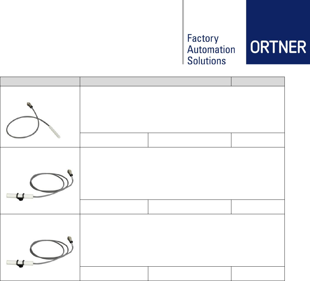
Ortner Test Suite
Comprehensive software tool for testing all Ortner CAN/Serial LF
and HF ID-readers in conjunction with a CAN2Web gateway.
For further information please contact our support:
ortner.support@roth-rau.com
Revision: 09 LF-134-CAN-M Low Frequency RFID Reader User Manual page 31 of 34
Component
Description
Order Codes
ANT04-35EMB
External Antenna
core diameter (4 mm)
core length (35 mm)
connector type (Binder / RJ10)
available cable lengths (0.5m / 1m / 2m)
ANT04-35EMB
different cable length available
000364, 000366,
000368
ANT08-65EMB
External Antenna
core diameter (8 mm)
core length (65 mm)
connector type (Binder / RJ10)
available cable lengths (0.5m / 1m / 2m)
ANT08-65EMB
different cable length available
000277, 000189,
000380
ANT08-65EMBF
External Antenna with High Flex Cable
core diameter (8 mm)
core length (65 mm)
connector type (Binder / RJ10)
available cable lengths (0.5m / 1m / 2m)
ANT08-65EMBF
different cable length available
000370, 000375,
000381
Revision: 09 LF-134-CAN-M Low Frequency RFID Reader User Manual page 32 of 34
13 Attachments
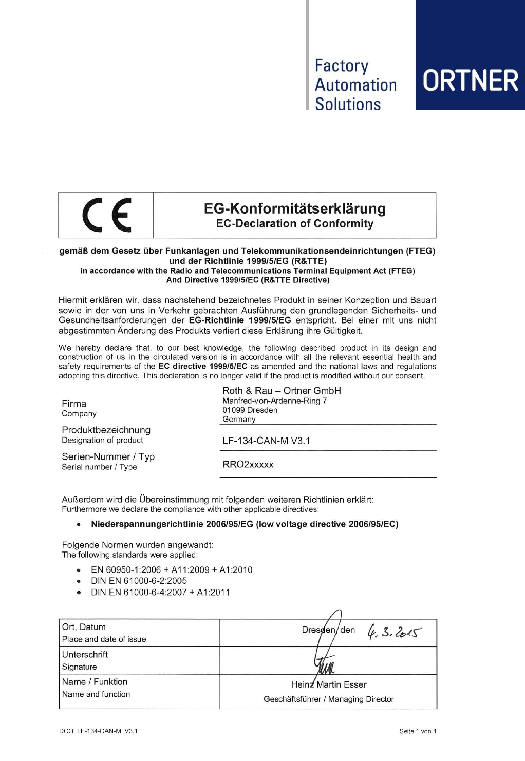
13.1 Declaration of conformity LF-134-CAN-M V3.1

Revision: 09 LF-134-CAN-M Low Frequency RFID Reader User Manual page 33 of 34
13.2 Glossary
ASCII
American Standard Code of Information Inter-exchange
CAN
Controller Area Network
RF
Radio Frequency
RFID
Radio Frequency IDentification
LF / HF
Low / High Frequency
HDX
Half DupleX
ISP
In-Circuit Programmer
FSK
Frequency Shift Keying
MPT / SPT
Multi / Single Page Transponder
RO / RW
Read Only / Read and Write
SAMPT
Selective Addressable Multi Page Transponder
ABS
Acrylonitrile Butadiene Styrene (plastic material)
POM
Polyoxymethylen (plastic material)
SMPS
Switched Mode Power Supply
MES
Manufacturing Execution System
SEMI
Semiconductor Equipment and Materials International
SECS
SEMI Equipment Communication Standard
MTBF
Mean Time Between Failures
MCBF
Mean Cycles Between Failures
TIRIS
Texas Instruments Registration and Identification System (RFID Standard)
13.3 Related documents
UMA_CAN2Web-Advanced_Rev12_Eng
The documents apply in their respective current version.