Fagor Cnc8070 Users Manual CNC 8070 Operating
CNC8070 to the manual 5cdfbb03-9dcb-4df2-bf61-7fa95d06c0c5
2015-02-02
: Fagor Fagor-Cnc8070-Users-Manual-402504 fagor-cnc8070-users-manual-402504 fagor pdf
Open the PDF directly: View PDF ![]() .
.
Page Count: 358 [warning: Documents this large are best viewed by clicking the View PDF Link!]
- List of manuals
- Operating manual
- Preliminary warnings
- INDEX
- Introduction
- 1. General concepts
- 2. How to operate the CNC
- 3. Automatic mode
- 4. Manual (jog) mode
- 5. Manual (jog) mode. Tool calibration
- 6. Editing-simulation mode
- 6.1 Appearance of the editing - simulation
- 6.2 Editing window
- 6.3 Editing window (softkeys)
- 6.4 Graphics window
- 6.5 Graphic window (softkeys)
- 6.6 Program window
- 6.7 Program window (softkeys)
- 6.8 Statistics window
- 6.9 Profile editor
- 6.9.1 Operating procedure
- 6.9.2 Data editing
- 6.9.3 Profile definition
- 6.9.4 Circular profile definition
- 6.9.5 Rectangular profile definition
- 6.9.6 Defining any profile
- 6.9.7 Modify a profile and insert corners
- 6.9.8 Display area
- 6.9.9 Work plane definition
- 6.9.10 End
- 6.9.11 Profile editor. Example 1
- 6.9.12 Profile editor. Example 2
- 6.9.13 Profile editor. Example 3
- 7. MDI mode
- 8. User tables
- 9. Tool and magazine table
- 10. Utilities mode
- 11. PLC
- 11.1 Appearance of the PLC mode
- 11.2 "Programs" service
- 11.3 Program editing
- 11.4 Program editing (softkeys)
- 11.5 Program monitoring
- 11.6 Program monitoring (softkeys)
- 11.7 "Commands" service
- 11.8 "Outputs" service
- 11.9 "Logic analyzer" service
- 11.10 "Monitoring" service
- 11.11 "Cross references" service
- 11.12 "Statistics" service
- 11.13 "Messages" service
- 12. Machine parameters
- 13. Setup assistance
- 13.1 Oscilloscope
- 13.2 The Bode diagram
- 13.3 The circularity (roundness) test
- 13.3.1 Interface description
- 13.3.2 Configuring and executing the circularity (roundness) test
- 13.3.3 Configure the graphic environment
- 13.3.4 Define and execute the movement subroutine
- 13.3.5 Data capture for the graphic
- 13.3.6 Adjustment of the machine parameters involved
- 13.3.7 Validate the changes and save the configuration used
- 13.3.8 Machine parameters that may be modified
- 14. DDSSetup
- 15. Diagnosis
- New features V3.01
CNC 8070
(REF. 0509)
(SOFT V03.0X)
OPERATING MANUAL
(Soft V03.0x) (Ref. 0509)

Unauthorized copying or distributing of this software is prohibited.
All rights reserved. No part of this documentation may be transmitted, transcribed, stored in a backup device
or translated into another language without Fagor Automation’s consent.
Microsoft
®
and Windows
®
are registered trademarks of Microsoft Corporation, U.S.A.
Operating manual
PRELIMINARY WARNINGS
MACHINE SAFETY
It is up to the machine manufacturer to make sure that the safety of the machine is enabled
in order to prevent personal injury and damage to the CNC or to the products connected to it.
On start-up and while validating CNC parameters, it checks the status of the following safety
elements:
• Feedback alarm for analog axes.
• Software limits for analog and sercos linear axes.
• Following error monitoring for analog and sercos axes (except the spindle) both at the
CNC and at the drives.
• Tendency test on analog axes.
If any of them is disabled, the CNC shows a warning message and it must be enabled to
guarantee a safe working environment.
FAGOR AUTOMATION shall not be held responsible for any personal injuries or physical
damage caused or suffered by the CNC resulting from any of the safety elements being
disabled.
HARDWARE EXPANSIONS
FAGOR AUTOMATION shall not be held responsible for any personal injuries or physical
damage caused or suffered by the CNC resulting from any hardware manipulation by
personnel unauthorized by Fagor Automation.
If the CNC hardware is modified by personnel unauthorized by Fagor Automation, it will no
longer be under warranty.
COMPUTER VIRUSES
FAGOR AUTOMATION guarantees that the software installed contains no computer viruses.
It is up to the user to keep the unit virus free in order to guarantee its proper operation.
Computer viruses at the CNC may cause it to malfunction. An antivirus software is highly
recommended if the CNC is connected directly to another PC, it is part of a computer network
or floppy disks or other computer media is used to transmit data.
FAGOR AUTOMATION shall not be held responsible for any personal injuries or physical
damage caused or suffered by the CNC due a computer virus in the system.
If a computer virus is found in the system, the unit will no longer be under warranty.
Operating manual

Operating manual
CNC 8070
(SOFT V03.0X)
i
INDEX
CHAPTER 1 GENERAL CONCEPTS
1.1 CNC configuration. Hardware.................................................................................... 1
1.2 Turning the CNC on and off....................................................................................... 3
1.2.1 Emergency shutdown with battery......................................................................... 4
1.3 Description of the keys .............................................................................................. 5
1.3.1 Keys associated with the information on the screen.............................................. 5
1.3.2 Keyboard layout ..................................................................................................... 6
1.3.3 Description of the operator panel........................................................................... 8
1.4 Directory structure ................................................................................................... 10
1.4.1 MTB (Machine Tool Builder) directory.................................................................. 11
1.4.2 USERS directory ................................................................................................. 12
CHAPTER 2 HOW TO OPERATE THE CNC
2.1 Screen description................................................................................................... 13
2.1.1 Detailed description of the CNC status bar.......................................................... 14
2.2 Operating modes ..................................................................................................... 16
2.2.1 How to access to the operating modes................................................................ 16
2.2.2 Description of the various operating modes ........................................................ 18
2.3 Dialog boxes ............................................................................................................ 20
2.4 Windows for warnings and errors ............................................................................ 21
2.5 File selection window............................................................................................... 22
2.6 Calculator ................................................................................................................ 25
2.6.1 Defining expressions............................................................................................ 27
2.7 Keyboard shortcuts.................................................................................................. 30
CHAPTER 3 AUTOMATIC MODE
3.1 Displaying the automatic mode................................................................................ 34
3.1.1 Description of the screens ................................................................................... 35
3.1.2 Description of the general status bar ................................................................... 36
3.1.3 Channel synchronization window ........................................................................ 37
3.1.4 Icon description (vertical softkeys)....................................................................... 38
3.2 Data screen ............................................................................................................. 39
3.3 Data screen (softkeys)............................................................................................. 41
3.3.1 First block............................................................................................................. 41
3.3.2 Stop condition ...................................................................................................... 42
3.3.3 Block search ........................................................................................................ 44
3.3.4 Find text ............................................................................................................... 46
3.3.5 Go to line ............................................................................................................. 46
3.4 Graphic screen ........................................................................................................ 47
3.5 Graphic screen (softkeys)........................................................................................ 49
3.5.1 Type of graphics................................................................................................... 49
3.5.2 Zoom.................................................................................................................... 50
3.5.3 Dimensions .......................................................................................................... 51
3.5.4 Point of view......................................................................................................... 52
3.5.5 Measurement....................................................................................................... 53
3.5.6 Clear screen ........................................................................................................ 53
3.5.7 Colors .................................................................................................................. 54
3.5.8 Options ................................................................................................................ 55
3.5.9 Real coordinates.................................................................................................. 56
3.6 Program selection and execution............................................................................. 57
3.6.1 Program selection ................................................................................................ 57
3.6.2 Program execution ............................................................................................... 58
3.6.3 Tool inspection ..................................................................................................... 59
3.6.4 Block search and program execution................................................................... 61
CHAPTER 4 MANUAL (JOG) MODE
4.1 Appearance of the Manual (JOG) mode.................................................................. 64
4.1.1 Description of a typical screen of this work mode................................................ 65
4.1.2 Vertical softkey menu (icons) ............................................................................... 66

Operating manual
CNC 8070
(SOFT V03.0X)
ii
4.2 Operations with the axes ......................................................................................... 67
4.2.1 Home search ....................................................................................................... 67
4.2.2 Jogging the axes.................................................................................................. 68
4.2.3 Jogging the axes with handwheels...................................................................... 70
4.2.4 Moving an axis to a particular position (coordinate) ............................................ 72
4.2.5 Coordinate preset ................................................................................................ 73
4.3 Spindle control......................................................................................................... 74
4.4 Tool selection and tool change ................................................................................ 75
4.5 Definition of cutting conditions................................................................................. 76
4.6 Automatic loading of zero offsets or fixture offset tables ......................................... 77
CHAPTER 5 MANUAL (JOG) MODE. TOOL CALIBRATION
5.1 Manual calibration. Calibration without a probe....................................................... 81
5.2 Semi-automatic calibration. Calibration with a probe .............................................. 84
5.3 Automatic calibration with a probe and a canned cycle........................................... 86
5.3.1 Mill or lathe model ("trihedron" geometrical configuration) .................................. 86
5.3.2 Lathe model ("plane" geometrical configuration)................................................. 89
CHAPTER 6 EDITING-SIMULATION MODE
6.1 Appearance of the editing - simulation .................................................................... 92
6.1.1 General screen description.................................................................................. 93
6.1.2 Window description ............................................................................................. 94
6.1.3 Icon description (vertical softkeys)....................................................................... 95
6.2 Editing window......................................................................................................... 97
6.2.1 Program editing ................................................................................................... 99
6.2.2 Import DXF files................................................................................................. 100
6.2.3 Syntax errors when editing ................................................................................ 101
6.3 Editing window (softkeys) ...................................................................................... 102
6.3.1 Open program.................................................................................................... 102
6.3.2 File..................................................................................................................... 103
6.3.3 Undo .................................................................................................................. 104
6.3.4 Operations with blocks....................................................................................... 105
6.3.5 Find/replace....................................................................................................... 106
6.3.6 Customizing....................................................................................................... 107
6.3.7 Profile editor ...................................................................................................... 109
6.3.8 Canned cycles ................................................................................................... 110
6.3.9 TEACH-IN ON / TEACH-IN OFF ....................................................................... 111
6.4 Graphics window ................................................................................................... 112
6.4.1 Program simulation............................................................................................ 114
6.4.2 Simulation errors................................................................................................ 116
6.5 Graphic window (softkeys)..................................................................................... 117
6.5.1 Type of graphics................................................................................................. 117
6.5.2 Zoom ................................................................................................................. 118
6.5.3 Dimensions........................................................................................................ 120
6.5.4 Point of view....................................................................................................... 121
6.5.5 Measurement..................................................................................................... 122
6.5.6 Clear screen ...................................................................................................... 122
6.5.7 Colors ................................................................................................................ 123
6.5.8 Options .............................................................................................................. 124
6.5.9 Speed ................................................................................................................ 125
6.6 Program window.................................................................................................... 126
6.7 Program window (softkeys) ................................................................................... 128
6.7.1 First block .......................................................................................................... 128
6.7.2 Stop condition.................................................................................................... 129
6.7.3 Find text ............................................................................................................. 131
6.7.4 Go to line ........................................................................................................... 131
6.8 Statistics window ................................................................................................... 132
6.8.1 Time estimates .................................................................................................. 133
6.9 Profile editor .......................................................................................................... 134
6.9.1 Operating procedure.......................................................................................... 136
6.9.2 Data editing ....................................................................................................... 137
6.9.3 Profile definition ................................................................................................. 138
6.9.4 Circular profile definition .................................................................................... 139
6.9.5 Rectangular profile definition ............................................................................. 140
6.9.6 Defining any profile............................................................................................ 141
6.9.7 Modify a profile and insert corners .................................................................... 143
6.9.8 Display area....................................................................................................... 145
6.9.9 Work plane definition ......................................................................................... 146
6.9.10 End .................................................................................................................... 147
6.9.11 Profile editor. Example 1.................................................................................... 148
6.9.12 Profile editor. Example 2.................................................................................... 149
6.9.13 Profile editor. Example 3.................................................................................... 150

Operating manual
CNC 8070
(SOFT V03.0X)
iii
CHAPTER 7 MDI MODE
7.1 Appearance of the MDI mode................................................................................ 152
7.1.1 Window description............................................................................................ 153
7.2 Standard MDI window ........................................................................................... 154
7.2.1 Block editing and execution ............................................................................... 155
7.3 Full MDI screen ..................................................................................................... 156
7.3.1 Block execution .................................................................................................. 158
7.3.2 Save the blocks as a program............................................................................ 159
CHAPTER 8 USER TABLES
8.1 Appearance of the table mode............................................................................... 162
8.1.1 Icon description (vertical softkeys)..................................................................... 163
8.2 Zero offset tables................................................................................................... 165
8.3 Fixture table........................................................................................................... 166
8.4 Arithmetic parameter tables................................................................................... 167
8.5 Operations with tables ........................................................................................... 168
8.5.1 Data editing........................................................................................................ 168
8.5.2 Save and recall tables........................................................................................ 169
8.5.3 Find text ............................................................................................................. 170
CHAPTER 9 TOOL AND MAGAZINE TABLE
9.1 Showing tables and common operations............................................................... 172
9.1.1 Table selection ................................................................................................... 172
9.1.2 Search for a text in the tables ............................................................................ 173
9.1.3 Save and load the tables ................................................................................... 174
9.1.4 Printing the tables .............................................................................................. 176
9.2 Tool table ............................................................................................................... 177
9.2.1 Description of the icons of the vertical softkey menu......................................... 178
9.2.2 The tool list ........................................................................................................ 180
9.2.3 Description of the tool data ................................................................................ 181
9.3 Operations with the tool table ................................................................................ 189
9.3.1 Editing the tool table .......................................................................................... 189
9.4 Active-tools table ................................................................................................... 190
9.4.1 Changing the tool of the spindle ........................................................................ 191
9.5 Table for the status of the tool change process ..................................................... 192
9.6 Magazine table ...................................................................................................... 193
9.6.1 Description of the icons of the vertical softkey menu......................................... 194
9.6.2 List of magazine positions ................................................................................. 196
9.6.3 Magazine information ........................................................................................ 197
9.7 Operations with the magazine table ...................................................................... 199
9.7.1 Loading / unloading tools to / from the magazine .............................................. 199
9.7.2 Load / unload a tool to / from the tool changer arm ........................................... 201
CHAPTER 10 UTILITIES MODE
10.1 Appearance of the utilities mode ........................................................................... 204
10.1.1 Screen description ............................................................................................. 205
10.1.2 Window description............................................................................................ 206
10.1.3 Vertical softkey menu (icons)............................................................................. 208
10.2 Utilities (Softkeys).................................................................................................. 210
10.2.1 Sorted by ........................................................................................................... 210
10.2.2 Options .............................................................................................................. 210
10.2.3 Search in files .................................................................................................... 211
10.2.4 Select all ............................................................................................................ 212
10.2.5 Invert selection................................................................................................... 212
10.2.6 New folder.......................................................................................................... 212
10.2.7 Protection passwords......................................................................................... 213
10.2.8 Data safety backup. Backup - Restore............................................................... 215
CHAPTER 11 PLC
11.1 Appearance of the PLC mode ............................................................................... 218
11.1.1 Screen description ............................................................................................. 219
11.1.2 Icon description (vertical softkeys)..................................................................... 220
11.2 "Programs" service ................................................................................................ 221
11.2.1 PLC project (softkeys)........................................................................................ 222
11.2.2 Files of the PLC project PLC (Softkey) .............................................................. 223
11.3 Program editing ..................................................................................................... 224

Operating manual
CNC 8070
(SOFT V03.0X)
iv
11.4 Program editing (softkeys)..................................................................................... 225
11.4.1 Analyze.............................................................................................................. 225
11.4.2 File ..................................................................................................................... 225
11.4.3 Undo .................................................................................................................. 226
11.4.4 Operations with blocks....................................................................................... 226
11.4.5 Find/Replace ..................................................................................................... 227
11.4.6 Customizing....................................................................................................... 228
11.5 Program monitoring............................................................................................... 229
11.6 Program monitoring (softkeys) .............................................................................. 230
11.7 "Commands" service ............................................................................................. 231
11.7.1 Options of the "Commands" service (softkeys) ................................................. 231
11.8 "Outputs" service................................................................................................... 232
11.8.1 Options of the "Outputs" service........................................................................ 233
11.9 "Logic analyzer" service ........................................................................................ 234
11.9.1 Editing logic analyzer data................................................................................. 235
11.9.2 Save, load and reset the analyzer configuration................................................ 237
11.9.3 Execute and analyze trace ................................................................................ 238
11.9.4 Customize the appearance of the logic analyzer............................................... 239
11.10 "Monitoring" service............................................................................................... 240
11.10.1 Description of resource tables ........................................................................... 241
11.10.2 Definition of the table resources ........................................................................ 242
11.10.3 Options of the "Monitoring" service (softkeys)................................................... 243
11.11 "Cross references" service .................................................................................... 244
11.11.1 Options of the "Cross reference" service (softkeys) .......................................... 245
11.12 "Statistics" service ................................................................................................. 246
11.12.1 Options of the "Statistics" service (softkeys) ..................................................... 247
11.13 "Messages" service ............................................................................................... 248
11.13.1 Options of the "Messages" service (softkeys) ................................................... 249
11.13.2 Editing the message and error table.................................................................. 250
11.13.3 Displaying PLC messages................................................................................. 251
11.13.4 Displaying PLC errors........................................................................................ 252
11.13.5 Save, load and print a message and error table................................................ 253
CHAPTER 12 MACHINE PARAMETERS
12.1 Appearance of the machine parameter tables....................................................... 257
12.1.1 Icon description (vertical softkeys)..................................................................... 258
12.2 Parameter table description................................................................................... 260
12.2.1 "M" function setting table ................................................................................... 261
12.2.2 Compensation table........................................................................................... 262
12.3 Operations with tables ........................................................................................... 263
12.3.1 Data editing and validation ................................................................................ 263
12.3.2 Save and recall tables ....................................................................................... 264
12.3.3 Find text ............................................................................................................. 265
CHAPTER 13 SETUP ASSISTANCE
13.1 Oscilloscope .......................................................................................................... 269
13.1.1 Interface description .......................................................................................... 270
13.1.2 Configuration screen.......................................................................................... 275
13.1.3 Configure and execute the oscilloscope function .............................................. 276
13.1.4 Machine parameter editing ................................................................................ 277
13.2 The Bode diagram ................................................................................................. 280
13.2.1 Interface description .......................................................................................... 281
13.3 The circularity (roundness) test ............................................................................. 285
13.3.1 Interface description .......................................................................................... 286
13.3.2 Configuring and executing the circularity (roundness) test................................ 289
13.3.3 Configure the graphic environment.................................................................... 290
13.3.4 Define and execute the movement subroutine .................................................. 291
13.3.5 Data capture for the graphic .............................................................................. 292
13.3.6 Adjustment of the machine parameters involved............................................... 293
13.3.7 Validate the changes and save the configuration used...................................... 295
13.3.8 Machine parameters that may be modified........................................................ 296
CHAPTER 14 DDSSETUP
14.1 Appearance of the DDSSetup mode ..................................................................... 298
14.1.1 Screen description............................................................................................. 299
14.1.2 Vertical softkey menu (icons)............................................................................. 300
14.2 List of drives .......................................................................................................... 301
14.3 Command bar........................................................................................................ 302
14.4 Changing the drives accessing level ..................................................................... 304
14.5 –Parameters and variables– service. .................................................................... 305
14.6 –Error management– service. ............................................................................... 307

Operating manual
CNC 8070
(SOFT V03.0X)
v
14.7 –Monitoring– service ............................................................................................. 308
14.8 –Information– service ............................................................................................ 309
14.9 Command generator.............................................................................................. 311
CHAPTER 15 DIAGNOSIS
15.1 Appearance of the diagnosis mode ....................................................................... 314
15.1.1 Screen description ............................................................................................. 315
15.1.2 Icon description (vertical softkeys)..................................................................... 316
15.2 Configuration diagnosis ......................................................................................... 317
15.2.1 System diagnosis............................................................................................... 317
15.2.2 Software diagnosis ............................................................................................ 318
15.2.3 Hardware diagnosis. CAN bus and SERCOS.................................................... 319
15.3 Sercos diagnosis ................................................................................................... 320
15.4 Save the CAN configuration for the start-up test. .................................................. 321
15.5 Generate a report with the system information...................................................... 322
CNC 8070
(SOFT V03.0X)
I
ABOUT THIS MANUAL
Title
Operating Manual.
Type of documentation
Description and operation of each table, windows and work modes of
the CNC.
Internal code
It is part of the manual directed to the end user. The code of the manual
depends on the software version –standard– or –advanced–.
Version
It corresponds to the software version: (Soft V03.0x).
Start-up
Warning
CNC 8070 USER (IN) STAN Code 03753611
CNC 8070 USER (IN) AVANZ Code 03753631
Verify that the machine that integrates this CNC meets the
89/392/CEE Directive.
Before starting up the CNC, read the instructions of chapter 1 in the
Installation Manual.
The information described in this manual may be changed due to
technical modifications.
FAGOR AUTOMATION, S. Coop. reserves the right to make any
changes to the contents of this manual without prior notice.
CNC 8070
(SOFT V03.0X)
III
ABOUT THE PRODUCT
Software options
Bear in mind that some of the features described in this manual
depend on the software options that are installed.
“GP” model “M” model “T” model
Number of execution channels 1 to 4 1 to 4 1 to 4
Number of axes 4 to 28 4 to 28 4 to 28
Number of spindles 1 to 4 1 to 4 1 to 4
Number of tool magazines 1 to 4 1 to 4 1 to 4
COCOM version Option Option Option
Sercos digital drive system Standard Standard Standard
Tool radius compensation Option Standard Standard
"C" axis Not available Standard Not available
RTCP transformation Not available Option Option
High speed machining (HSC). Option Option Option
Probing canned cycles Option Option Option
Tandem axes Option Option Option
Synchronism and cams Not available Option Option
CNC 8070
(SOFT V03.0X)
V
VERSION HISTORY
Here is a list of the features added in each software version and the manuals that describe them.
The version history uses the following abreviations:
Software V01.01 February of 2002
First version.
Software V1.11 September 2002
INST Installation manual
PRG Programming manual
OPT Operation manual
Feature
Probe management through a digital input. It is not possible to manage it through the
“Counter” module connector.
INST
Set the numbering of the digital I/O. INST
Kinetics for rotary table. INST
Possibility to park and unpark SERCOS axes from the PLC. INST
Keyboard simulation from the PLC. INST
New treatment of the JOG panel (Key + Direction). INST / OPT
New machine parameters.
• Probe setting.
• Numbering of the digital I/Os.
• Kinetics for rotary table.
• Repositioning feedrate after a tool inspection.
INST
New variables.
• Probe setting.
• Numbering of the digital I/Os.
• Key simulation.
• Repositioning feedrate after a tool inspection.
• General scaling factor.
• Kinetics dimensions.
INST
PRG
General scaling factor (#SCALE). PRG
Pobring canned cycles (#PROBE). PRG
Probe selection (#SELECT PROBE). PRG
Programming of warnings (#WARNING). PRG
Block repetition ($RPT). PRG
Improved programming of high speed machining (#HSC). PRG
Improved programming of axis swapping (#SET AX, #CALL AX, #FREE AX, #RENAME). PRG
Macros: The number of macros in a program is now limited to 50. PRG
Improved tool table. OPT
Protection passwords. OPT
Jog mode. Tool calibration with or without probe. OPT
Jog mode. Automatic loading of zero offsets table. OPT
VIII
CNC 8070
Version history
(SOFT V03.0X)
VI
Software V2.01 January 2005
Jog mode. Programming of feedrate “F” and spindle speed “S”. OPT
Axis selection/deselection for handwheel jog. OPT
Theoretical path simulation. OPT
Definition of the first block of a block search. OPT
Confirm that the CNC is not in automatic mode when executing a program. OPT
Syntax check in MDI. OPT
Feature
Feature
Operation under Windows XP INST
Emergency shutdown with battery (Central unit PC104) OPT
New languages (Basque and Portuguese) INST
Multi-channel system, up to 4 channels.
• Spindle swapping
• Axis swapping
• Communication and synchronization between channels.
• Common arithmetic parameters.
• Access to variables per channel.
INST
PRG
OPT
Multi-spindle system, up to 4 spindles PRG / INST
Tool management with up to 4 magazines. INST
Tandem axis. INST
New kinematics table-spindle (TYPE13 to TYPE16). INST
New kinematics for C axis (TYPE 41 to TYPE 43) INST
Parameter matching between the CNC and the Sercos drive INST
New machine parameters.
• Warning level on Gantry axes (WARNCOUPE)
• Placing the vertical softkeys on the right or on the left (VMENU).
• Apply cross compensation to either theoretical or real coordinates (TYPCROSS).
• Apply leadscrew compensation to either theoretical or real coordinates (TYPLSCRW).
• Defining the default compensation mode (IRCOMP).
• Defining the type of reference pulse (REFPULSE).
• Memory sharing between applications (PLCDATASIZE).
• Generic OEM machine parameters (MTBPAR).
• Reading Sercos variables from the CNC (DRIVEVAR).
• Backlash peak compensation (BAKANOUT, BAKTIME, ACTBAKAN).
INST
The behavior of rotary axes has been changed. Machine parameters AXISMODE,
UNIDIR, SHORTESTWAY.
INST
Possibility of Sercos transmission at 8 Mhz and 16 Mhz. Parameter SERBRATE. INST
Define the anticipation time for the axes to be considered to be in position. Machine
parameter ANTIME and the PLC mark ADVINPOS.
INST
The "(V.).TM.MZWAIT " variable is not necessary in the subroutine associated with M06. INST
Filters to eliminate the resonance of the spindle when it works as C axis or in rigid tapping. INST
PLC. The TMOPERATION may take the values 13 and 14. INST
PLC. New mark MMCWDG to detect that the lockup of the operating system. INST
PLC. Accessing arithmetic parameters and OEM parameters with CNCRD returns the
value multiplied by 10000 (reading in float mode).
INST
PLC. The CNCEX command and the FREE mark to execute a CNC block.
New commands at the PLC.
• New mark to disable the cross compensation tables (DISCROSS).
• New mark to correct the parallelism on Gantry axes (DIFFCOMP).
• Definition of external symbols (PDEF).
INST
New variables.
• Software version.
• Variables to be set via PLC.
• Variables for adjusting the position.
• Fine adjustment variables.
• Feedback inputs.
INST / PRG
CNC 8070
Version history
(SOFT V03.0X)
VII
Software V2.03 April 2005
Electronic-cam editor. INST
Optimize the reading and writing of variables from the PLC. Only the following will be
asynchronous.
• The tool variables will be read asynchronously when the tool is neither the active one
nor in the magazine.
• The tool variables will be written asynchronously whether the tool is the active one or
not.
• The variables referred to local arithmetic parameters of the active levels will be read
and written asynchronously.
INST / PRG
Spindle parking and unparking. INST
The RESETIN mark is not necessary to park/unpark axes or spindles from the PLC. INST
Sercos control in velocity. INST
Behavior of the beginning and end of tool radius compensation when not programming
a movement.
PRG
Changing the type of radius compensation while machining. PRG
Via program, loading a tool in a specific magazine position. PRG
Programming of modal subroutines (#MCALL). PRG
Executing a block in a channel (#EXBLK). PRG
Programming the number of repetitions in the block (NR). PRG
Direct resolution of 2D and 3D pockets without requiring a softkey. PRG
Simulating a canned cycle of the editor separately. PRG
New method to jog the axes using the JOG keyboard. Axis keys and independent
directions.
INST / OPT
Importing DXF files from the program editor or from the profile editor. OPT
Importing programs of the 8055/8055i CNC from the program editor. OPT
Use a softkey to select the repositioning of the spindle after tool inspection. OPT
Backup-restore utility. OPT
Improved profile editor. OPT
Assistance in the program editor. Contextual programming assistance.
• When programming "#", it shows the list of instructions.
• When programming "$", it shows the list of instructions.
• When programming "V.", it shows the list of variables.
OPT
Specific password for the machine parameters for kinematics. OPT
Save the CAN configuration for testing it when starting up the system. OPT
The diagnosis mode shows detailed information on the Sercos connection (Type and
version of the drive and motor connected to it).
OPT
It is possible to print all the information on the configuration from any section of the
diagnosis mode.
OPT
It is possible to simulate a cycle separately from the cycle editor. OPT
Setup assistance.
• Oscilloscope.
• Bode diagram.
• Circularity (roundness) test.
OPT
Feature
Feature
New values of machine parameter SERPOWSE for the "Sercos II" board. INST
Independent-axis programming commands. INST
Electronic-cams programming commands. INST
New signals that may be consulted and changed for the independent interpolator
(electronic cam and independent axis)
INST
The simulated axes are ignored regarding the validation code.
When unifying parameters, G00FEED and MAXVOLT are not sent out to the drive. INST
Electronic-cam programming instructions (#CAM ON / #CAM OFF). PRG
Independent-axis programming instructions (#MOVE ABS / #MOVE ADD / #MOVE INF
/ #FOLLOW ON / #FOLLOW OFF).
PRG
G112. Change the drive's parameter set. PRG
DDSSETUP mode OPT
G31. Temporary polar origin shift to the center of interpolation. PRG
VIII
CNC 8070
Version history
(SOFT V03.0X)
VIII
Software V3.01 July 2005
Feature
Lathe model
New machine parameters.
• CAN bus type selection (CANMODE).
• permit using the G95 function in jog mode (FPRMAN).
• Lathe model. Graphics configuration selection (GRAPHTYPECH).
• Lathe model. Axis configuration selection (GEOCONFIG).
• Set of parameters for synchronization (SYNCSET)
• Improved definition of kinematics for the C axis.
• Magazine-less system.
INST
Commands CNCRD and CNCWR. The channel number and the indexes may be defined
in the variables using an integer, a register or a symbol.
INST
Ground tools for a turret magazine. The TMOPERATION may take the values 3, 4, 9 and
10.
INST
Incline axis. INST / PRG
Improved coordinate transformation (#CS/#ACS).
• Keep the part zero when deactivating the transformation.
• Working with 45º spindles. Select between the two choices.
• Keep the rotation of the plane axes with MODE 6.
PRG
G33. New parameter (Q1) to define the entry angle. PRG
G63. Tool inspection is possible during rigid tapping. PRG
G112. G112 is no longer admitted for the spindle.
Kinetics definition when activating the C axis (#FACE / #CYL). PRG
Change of criteria when assuming a new master spindle in the channel. PRG
Selecting the loop for an axis or a spindle (#SERVO ON/OFF) PRG
Spindle synchronization (#SYNC/#TSYNC/#UNSYNC) PRG
Canned cycle selection (#MILLCY/#LATHECY) PRG
New variables:
• Variable to read the accumulated PLC offset.
• Variable to obtain a linear estimation of the following error.
• Variables to read the instant value of feed-forward or AC-forward.
• Variable to know the line number of the file being executed.
• Variable to know what kind of cycle is active.
• Variable to know the tool orientation.
• Variable to know whether the HSC mode is active or not.
• Variable to know the theoretical feedrate on 3D path.
• Variable to know the number of the warning being displayed.
• The variable (V.)G.CNCERR is now per channel.
INST / PRG
Improved tool table. OPT
CNC 8070
(SOFT V03.0X)
IX
DECLARATION OF CONFORMITY
Manufacturer:
Fagor Automation, S. Coop.
Barrio de San Andrés 19, C.P. 20500, Mondragón -Guipúzcoa-
(SPAIN).
We declare:
under our responsibility that the product:
Fagor CNC8070 Numerical Control
meets the following directives:
Safety:
Electromagnetic compatibility:
As instructed by the European Community Directives 73/23/EEC,
modification 93/68/ECC on Low Voltage and 89/336/CEE on
Electromagnetic Compatibility.
In Mondragón on February 1st 2002.
EN 60204-1 Machine safety. Electrical equipment of the machines.
EN 50081-2 Emission.
EN 55011 Radiated. Class A, Group 1.
EN 55011 Conducted. Class A, Group 1.
EN 61000-3-2 Current armonics.
EN 61000-3-3 Flickers and Voltage fluctuations.
EN 50082-2 Immunity.
EN 61000-4-2 Electrostatic discharges.
EN 61000-4-4 Bursts and Fast transients.
EN 61000-4-5 High Voltage conducted pulses (Surges).
EN 61000-4-11 Voltage fluctuations and Outages.
EN 61000-4-3 Radiofrequency radiated electromagnetic fields.
EN 61000-4-6 Conducted disturbance induced by radio frequency fields.
CNC 8070
(SOFT V03.0X)
XI
SAFETY CONDITIONS
Read the following safety measures in order to prevent harming people or damage to this product
and those products connected to it.
This unit may only be repaired by authorized personnel at Fagor Automation.
Fagor Automation shall not be held responsible of any physical damage or defective unit
resulting from not complying with these basic safety regulations.
PRECAUTIONS AGAINST PERSONAL DAMAGE
Interconnection of modules.
Use the connection cables provided with the unit.
Use proper cables.
To prevent risks, use the proper cables for mains, Sercos and Bus Can
recomended for this unit.
Avoid electrical overloads.
In order to avoid electrical discharges and fire hazards, do not apply electrical
voltage outside the range selected on the rear panel of the Central Unit.
Ground connection.
In order to avoid electrical discharges, connect the ground terminals of all the
modules to the main ground terminal. Before connecting the inputs and outputs
of this unit, make sure that all the grounding connections are properly made.
Make sure that it is connected to ground.
In order to avoid electrical shock, before turning the unit on verify that the ground
connection is properly made.
Do not work in humid environments.
In order to avoid electrical discharges, always work under 90% of relative
humidity (non-condensing) and 45ºC (113ºF).
Do not work in explosive environments.
In order to avoid risks or damages, do no work in explosive environments.
PRECAUTIONS AGAINST PRODUCT DAMAGE
Working environment.
This unit is ready to be used in Industrial Environments complying with the
directives and regulations effective in the European Community.
Fagor Automation shall not be held responsible for any damage suffered or
caused when installed in other environments (residential or homes).
Install the unit in the right place.
XIII
CNC 8070
Safety conditions
(SOFT V03.0X)
XII
It is recommended, whenever possible, to install the CNC away from coolants,
chemical product, blows, etc. that could damage it.
This unit complies with the European directives on electromagnetic
compatibility. Nevertheless, it is recommended to keep it away from sources of
electromagnetic disturbance such as:
•Powerful loads connected to the same AC power line as this equipment.
•Nearby portable transmitters (Radio-telephones, Ham radio transmitters).
•Nearby radio/TV transmitters.
•Nearby arc welding machines.
•Nearby High Voltage power lines.
•Etc.
Enclosures.
The manufacturer is responsible of assuring that the enclosure involving the
equipment meets all the currently effective directives of the European
Community.
Avoid disturbances coming from the machine tool.
The machine-tool must have all the interference generating elements (relay
coils, contactors, motors, etc.) uncoupled.
Use the proper power supply.
Use an external regulated 24Vdc power supply for the keyboard and the remote
modules.
Grounding of the power supply.
The zero volt point of the external power supply must be connected to the main
ground point of the machine.
Analog inputs and outputs connection.
It is recommended to connect them using shielded cables and connecting their
shields (mesh) to the corresponding pin (see chapter 1 in the Installation
Manual).
Ambient conditions.
The working temperature must be between +5ºC and +45ºC (41ºF and 113ºF)
The storage temperature must be between -25ºC y 70ºC (-13ºF y 158ºF)
Monitor enclosure.
Make sure that the gaps between the Central Unit and each wall of the enclosure
are respected as indicated in chapter 1 of the Installation Manual.
Use a DC fan to improve enclosure ventilation.
Main AC power switch.
This switch must be easy to access and at a distance between 0.7 and 1.7 m
(2.3 and 5.6 ft) off the floor.
PROTECTIONS OF THE UNIT ITSELF
Remote modules.
All the digital inputs and outputs have galvanic isolation via optocouplers
between the CNC circuitry and the outside.
CNC 8070
Safety conditions
(SOFT V03.0X)
XIII
PRECAUTIONS DURING REPAIR
Do not get into the inside of the unit.
Only personnel authorized by Fagor Automation may manipulate the inside of
this unit.
Do not handle the connectors with the unit connected to AC power.
Before manipulating the connectors (inputs/outputs, feedback, etc.) make sure
that the unit is not connected to AC power.
SAFETY SYMBOLS
Symbols that may appear on the manual.
Symbols that the product may carry.
Symbol of danger or prohibition.
It indicates actions or operations that may hurt people or damage
products.
Warning symbol.
It indicates situations that certain operations could cause and the
suggested actions to prevent them.
Obligation symbol.
It indicates actions and operations that must be carried out.
Information symbol.
It indicates notes, warnings and advises.
i
Ground protection symbol.
It indicates that that point must be under voltage.

CNC 8070
(SOFT V03.0X)
XV
WARRANTY TERMS
All products manufactured or marketed by Fagor Automation has a warranty period of 12 months
from the day they are shipped out of our warehouses.
The mentioned warranty covers repair material and labor costs, at Fagor Automation facilities,
incurred in the repair of the products.
Within the warranty period, Fagor Automation will repair or replace the products verified as being
defective.
Fagor Automation is committed to repairing or replacing their products from the time they launch
them up to 8 years after they disappear from the product catalog.
It is entirely up to Fagor Automation to determine whether a repair is to be considered under
warranty.
Excluding clauses
The repair will take place at our facilities; therefore, all shipping expenses as well as travelling
expenses incurred by technical personnel are NOT under warranty even when the unit is under
warranty.
This warranty will be applied so long as the equipment has been installed according to the
instructions, it has not been mistreated or damaged by accident or negligence and has been
manipulated by personnel authorized by Fagor Automation.
If once the service call or repair has been completed, the cause of the failure is not to be blamed
ON the FAGOR product, the customer must cover all generated expenses according to current
fees.
No other implicit or explicit warranty is covered and FAGOR AUTOMATION shall not be held
responsible, under any circumstances, of the damage which could be originated.
Service contracts
Service and Maintenance Contracts are available for the customer within the warranty period
as well as outside of it.

CNC 8070
(SOFT V03.0X)
XVII
MATERIAL RETURNING TERMS
When sending the Central Unit or the Remote Modules, pack them in its original package and
packaging material. If the original packaging material is not available, pack it as follows:
1. Get a cardboard box whose three inside dimensions are at least 15cm (6 inches) larger than
those of the unit. The cardboard being used to make the box must have a resistance of 170Kg
(375 lb.).
2. Attach a label indicating the owner of the unit, person to contact, type of unit and serial
number. In case of malfunction also indicate symptom and a brief description of the problem.
3. Wrap the unit in a polyethylene roll or similar material to protect it.
When sending the Central Unit, protect especially the screen.
4. Pad the unit inside the cardboard box with poly-utherane foam on all sides.
5. Seal the cardboard box with packing tape or industrial staples.

CNC 8070
(SOFT V03.0X)
XIX
ADDITIONAL REMARKS
Mount the CNC away from coolants, chemical products, blows, etc. which could damage it.
Before turning the unit on, verify that the ground connections have been properly made.
In order to avoid electrical shock at the Central Unit, use the proper power (mains) cable. Use
3-wire power cables (one for ground connection).
In case of a malfunction or failure, disconnect it and call the technical service. Do not get into
the inside of the unit.
CNC 8070
(SOFT V03.0X)
XXI
RELATED DOCUMENTATION
Manuals directed to the machine manufacturer or to the person in
charge of doing the installation and start-up of the CNC.
Hardware manual.
It describes the hardware configuration and the technical data of
each element.
Installation Manual.
It describes how to install and start up the CNC.
Manuals directed to the end user; that is, to the CNC operator.
Operating Manual.
Describes how to operate the CNC.
Programming Manual.
It describes how to program the CNC.
Examples manual.
It contains programming examples.
Other manuals, directed to the machine manufacturer and to the end
user.
Manual for New Features.
It is optional. It describes the new features and modifications
implemented since the version of the installation, operating and
programming manuals.
Error solving manual.
It offers a description of the error messages that may appear on
the CNC indicating the probable causes that originate them and
how to solve them.

1
CNC 8070
(SOFT V03.0X)
1
GENERAL CONCEPTS
This manual describes how to operate with the CNC using the keyboard, monitor and
the operator panel. It also describes the various CNC operating modes as well as how
to operate with each of them.
1.1 CNC configuration. Hardware
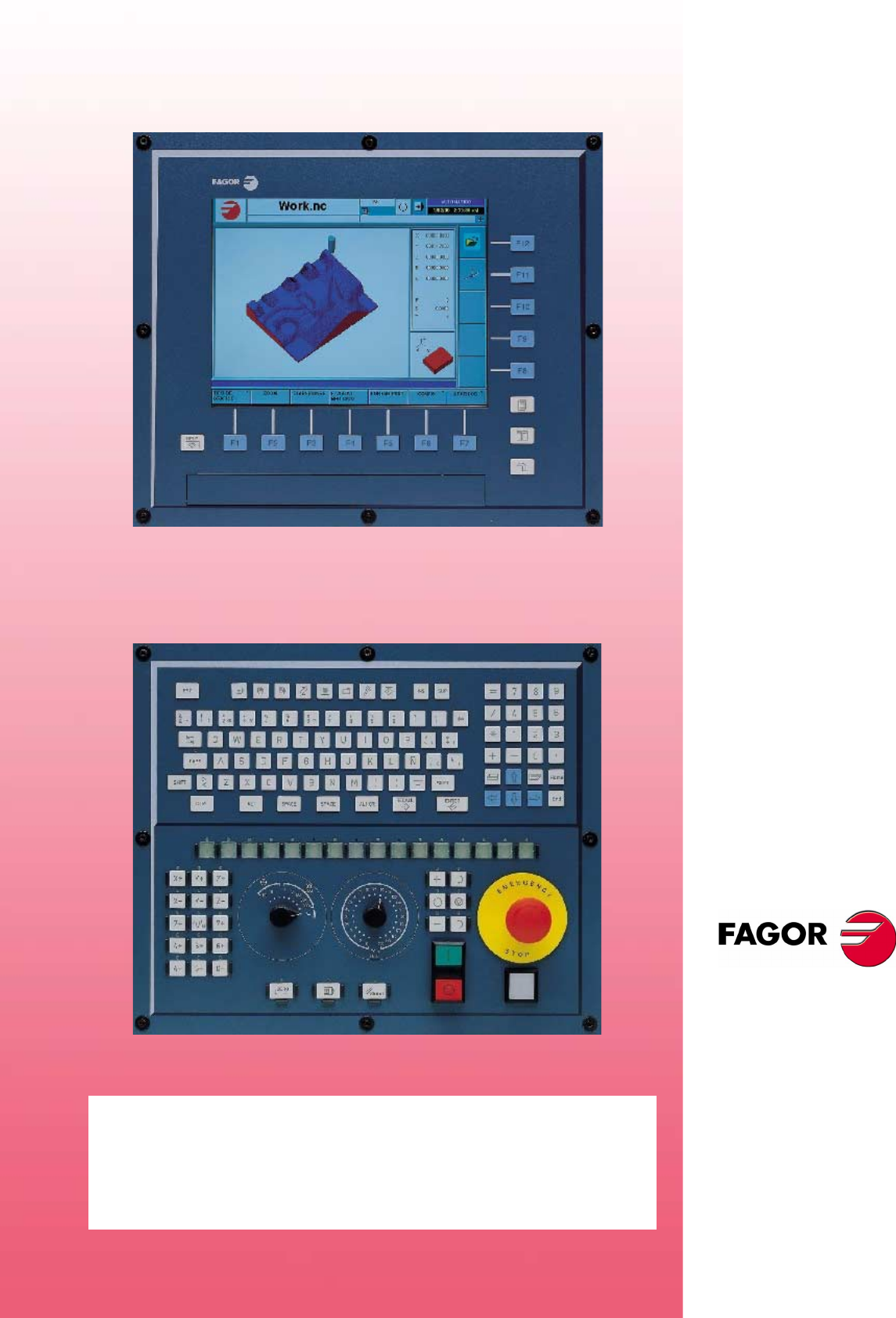
Monitor, keyboard and operator panel
The CNC assembly comprises the monitor, keyboard and the operator panel.
•The monitor shows the CNC's status and, in general, the information about the
whole system.
•The keyboard is used to communicate with the CNC; the operator may request
information on commands or change the CNC status using new instructions.
•The operator panel is used to govern the various elements of the machine,
including the movement of the axes and the control of the spindle, etc.
Modules
Depending on the CNC model, it may be connected in different ways. For example,
it would be possible to connect devices such as:
•Floppy disk drive.
•CD-ROM unit.
•Printer.
•PC-compatible keyboard.
•Mouse with PS-2 connector.
•Devices with USB interface.
•Ethernet connection.
•Etc.
For further information, see the hardware manual.

Operating manual
CNC 8070
1.
GENERAL CONCEPTS
CNC configuration. Hardware
(SOFT V03.0X)
2
Network connection (Ethernet)
The CNC may be connected to a computer network through specific connectors. The
CNC must be configured as any node of the network as if it were a regular PC.
The following actions are possible when having a CNC configured as a node within
the computer network:
•Access from any PC to the part-program directory of the CNC.
•Access from the CNC to any PC, to execute, simulate or edit programs. The
program to be executed needs not be in the local disk.
•Copy programs and tables from the CNC to a PC and vice versa.
•Edit, modify, delete, rename, etc. the programs stored at the CNC.
•Perform a telediagnosis of the CNC.
Operating manual
CNC 8070
GENERAL CONCEPTS
Turning the CNC on and off
1.
(SOFT V03.0X)
3
1.2 Turning the CNC on and off
The way the CNC is turned on and off depends on how it has been set by the machine
manufacturer. However, the most common way to do it is as follows.
Turning the CNC on
After powering up the unit, the operating system (Windows 95 or Windows XP) will
start up first. Then, and depending on how the manufacturer has set it, the CNC8070
application will either start up automatically or will have to be initiated by clicking on
the icon shown on the screen.
While starting up, it will display the initial standard CNC screen or the initial screen
created by the machine manufacturer for that purpose. Once the CNC is running, it
will show the screen for the work mode (automatic or jog) selected by the machine
manufacturer.
Turning the CNC off
To turn the CNC off, press the key combination [ALT]+[F4]. In any case, the CNC must
not be turned off if there is any program in execution.
After closing the CNC application and depending on how the manufacturer has set
it, the unit will turn off automatically or it will be required to select Shut down the system
option of the Start menu.
Once the application is closed, the screen will show a message indicating to the
operator that the unit may then be turned off.
The unit must be turned off with the on/off switch after having closed the
application using the key combination mentioned earlier.
Turning the unit off incorrectly may cause the loss of information about:
• Active offsets (zero offsets, part offset, etc.).
• Coordinates.
• Parts counter.
• Active axis sets.
• Information about the next tool.
If on power-up, it displays the error " 12 - Checksum error in CNC data", it
means that the CNC has been turned incorrectly (due to a power failure, etc.)
and consequently that information has been lost:
When this error message is displayed, home (reference) the axes again and
activate the offsets (part zero included) and the sets of axes.

Operating manual
CNC 8070
1.
GENERAL CONCEPTS
Turning the CNC on and off
(SOFT V03.0X)
4
1.2.1 Emergency shutdown with battery
The central unit PC104 is powered by an external 24Vdc power supply. Optionally,
an external battery may be connected to ensure the detection of power supply voltage
drops and that the unit is turned off properly.
When a power supply failure occurs (24V voltage drop) and there is a battery
connected to the central unit, the latter responds as follows:
•If the supply is interrupted for less than 2 seconds.
The screens shows the corresponding warning and the system recovers fine.
CAN errors may occur due to the lack of 24V at the remote modules.
•If the supply is interrupted for more than 2 seconds.
After the 2 seconds, the screen shows the corresponding error and it initiates the
automatic turn-off sequence. First, it stops the machine if it is in execution. It
closes the CNC8070 application, then the whole system and finally turns the
battery off.
Operating manual
CNC 8070
GENERAL CONCEPTS
Description of the keys
1.
(SOFT V03.0X)
5
1.3 Description of the keys
1.3.1 Keys associated with the information on the screen
Softkeys
The softkeys or functions keys may be used to select the different options shown on
the screen.
Using the screens
Help
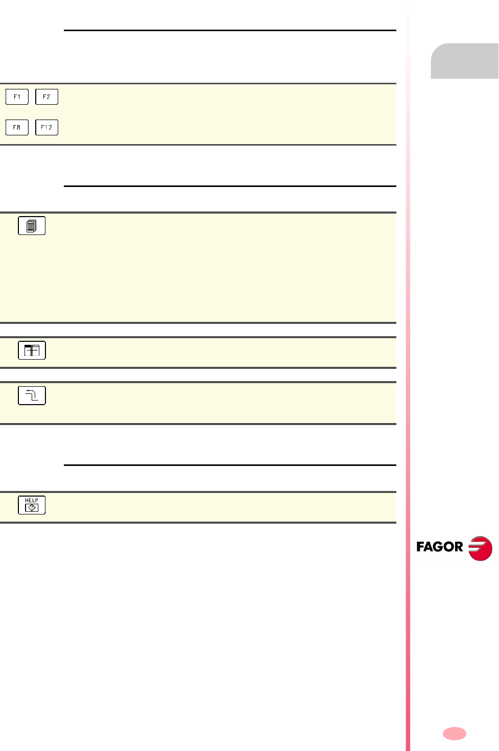
Horizontal softkeys.
It selects the options of the horizontal menu.
Vertical softkeys.
It selects the options of the vertical icon menu.
Screen change.
Depending on how the OEM has set this key, it will be possible to perform one of
the following operations.
•Sequentially access the different screens of the active work mode. In the PLC
mode, it switches between the various active services.
•Sequentially access the different channels.
•The horizontal softkey menu shows the available screens and the vertical menu
shows the available channels.
Window change.
It is used to switch between the different windows of the screen.
Previous menu.
On the horizontal softkey menu, it lets you go up from the softkey sub-menu to the
previous level from where that menu was accessed.
Help.
It accesses the CNC's system help.
Operating manual
CNC 8070
1.
GENERAL CONCEPTS
Description of the keys
(SOFT V03.0X)
6
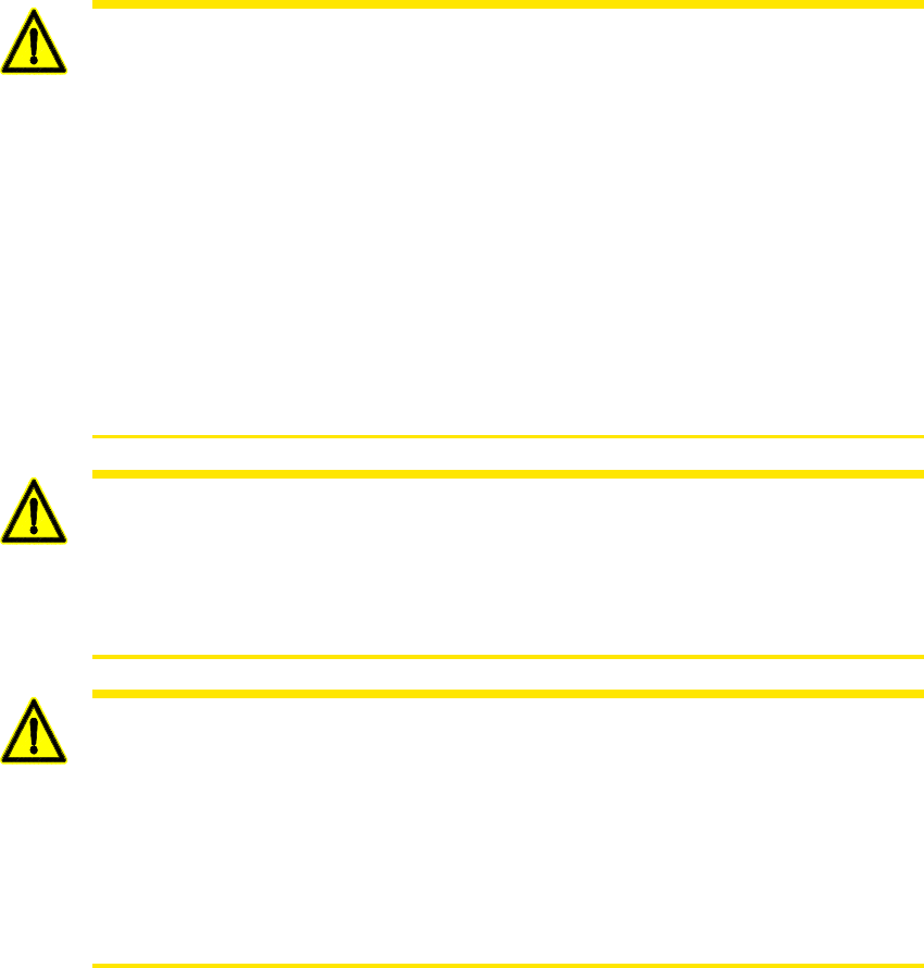
1.3.2 Keyboard layout
Depending on the utility of the different keys, the CNC keyboard may be considered
to be laid out as follows.
Work modes
To access the different CNC work modes directly.
Numeric keypad
It includes the necessary keys to enter numeric data and define the arithmetic
operations as well as the following special keys:
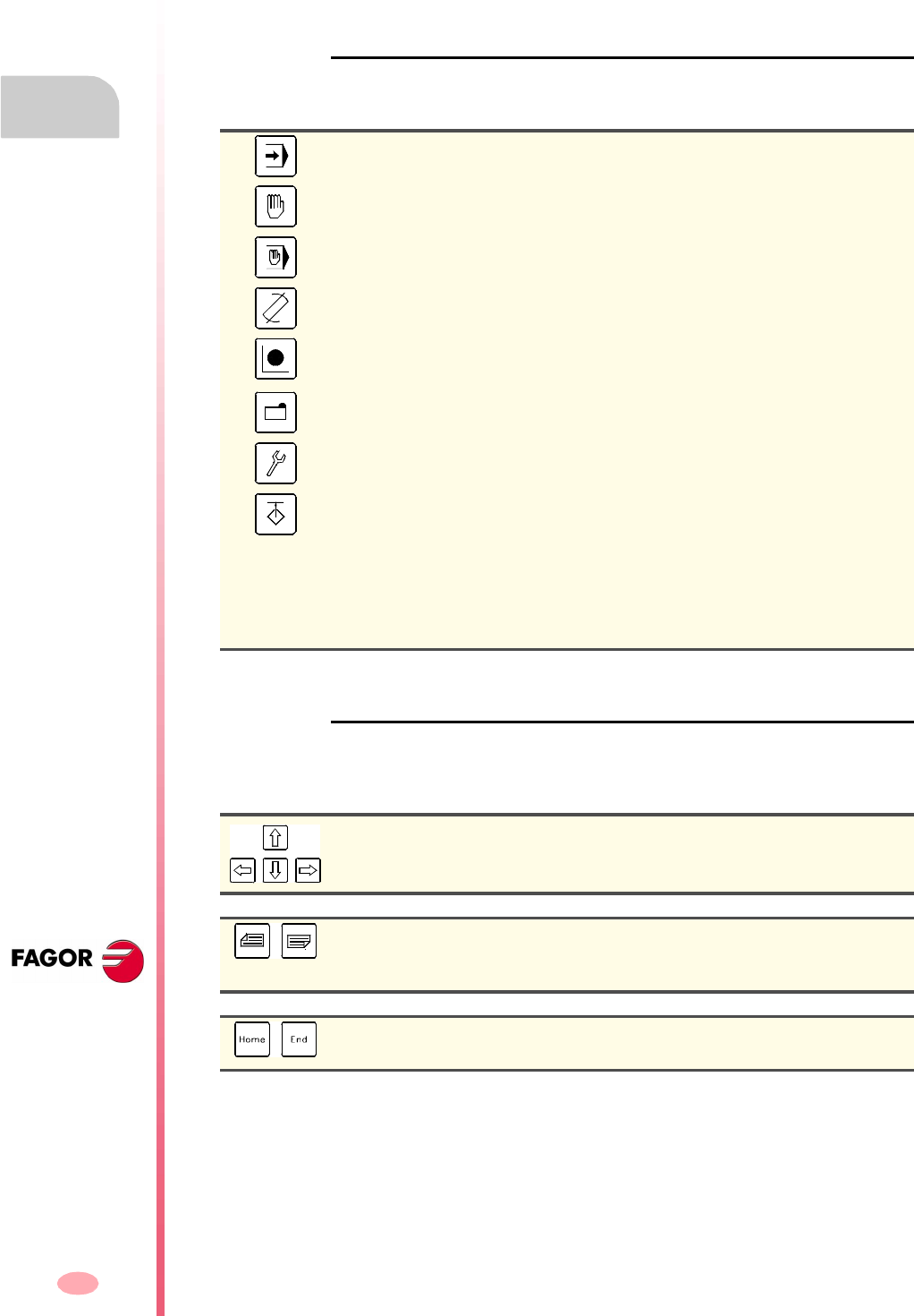
Automatic mode.
Jog mode.
MDI mode.
Editing - simulation mode.
User tables.
Zero offsets, fixtures and arithmetic parameters.
Tool and magazine table.
Utilities mode.
Configurable mode.
Depending on how the OEM has set this key it will be possible to:
•Access a CNC work mode.
•Execute an application.
•Access the operating system.
•Carry out no function at all.
Movement arrow keys.
They move the cursor one position to the left, right, up or down.
Previous or next page.
They show the previous or next page when the program (part-program or PLC
program) has more than one information page.
Home and end keys.
It moves the cursor the beginning or end of the line.
Operating manual
CNC 8070
GENERAL CONCEPTS
Description of the keys
1.
(SOFT V03.0X)
7
Alphanumeric keyboard
It includes the necessary keys to edit programs as well as the following special keys:
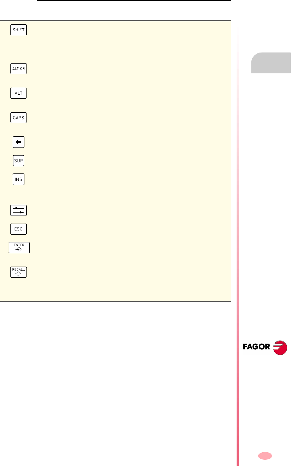
Shift key for capital letters.
By keeping it pressed and in combination with a another key, it accesses a second
set of characters for that other key shown at the top of that key. When combined
with a letter, it writes it in capital letters.
When combined with arrow keys, it selects the text the cursor slides on.
Alternate characters.
By keeping it pressed in combination with another key, it accesses the third set of
character of the that key, shown at the bottom right of that key.
ASCII characters.
If a number is keyed in while keeping this key pressed, it will write the character
corresponding to the ASCII code keyed in.
Capital letters.
It toggles between uppercase and lowercase letters. It only affects alphabetical
characters.
Delete character (back space).
It deletes the character to left of the cursor.
Deleted character.
It deletes the character to the right of the cursor or the selected text.
Insert or overwrite.
It toggles between insert and overwrite modes. When inserting, the new text is
added to the previous one, whereas when overwriting, the new text replaces the
previous one.
Tab.
It moves the cursor to the next field of the active menu.
Escape key
It cancels the current operation without assuming the changes.
Command validation.
It is used to validate the data of the current operation and the program blocks edited
in editing - simulation mode.
Data recall.
Having the TEACH-IN option active, it enters the axis position value into the block
being edited.
When selecting a profile or conversational canned cycle in the part-program, it
accesses either the profile editor or canned cycle editor accordingly.
Operating manual
CNC 8070
1.
GENERAL CONCEPTS
Description of the keys
(SOFT V03.0X)
8
1.3.3 Description of the operator panel
Depending on the utility of the different elements, the operator panel may be
considered to be laid out as follows:
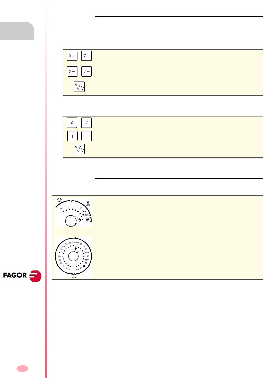
JOG keys
They are used to jog the axes. There are two types of JOG panels:
There are two keys for each axis. One to jog the axis in the positive direction and
another one to move it in the negative direction.
There is a key for each axis and two keys for moving direction, common to all the axes.
Both keys (axis and direction) must be pressed to jog the axis.
Feed selectors
The operator panel has two selectors:
Jogging the axis in the positive direction.
The movement is carried out at the jog feedrate.
Jogging the axis in the negative direction.
The movement is carried out at the jog feedrate.
Rapid jogging of the axis.
When combined with another JOG key, it moves the axis at rapid jog feedrate.
Axis selection.
Selection of the moving direction.
Rapid jogging of the axis.
When combined with another JOG key, it moves the axis at rapid jog feedrate.
Movement type selector.
Select the type of jog movement, which may be either by handwheels, incremental
jog or continuous jog.
In handwheel mode, it selects the multiplying factor for the handwheel pulses (x1,
x10 o x100).
In incremental mode, it selects the incremental value of the axis movements.
Feedrate override % selector.
To select the override percentage to be applied to the programmed and jog
feedrates, between 0% and 200%.
Operating manual
CNC 8070
GENERAL CONCEPTS
Description of the keys
1.
(SOFT V03.0X)
9
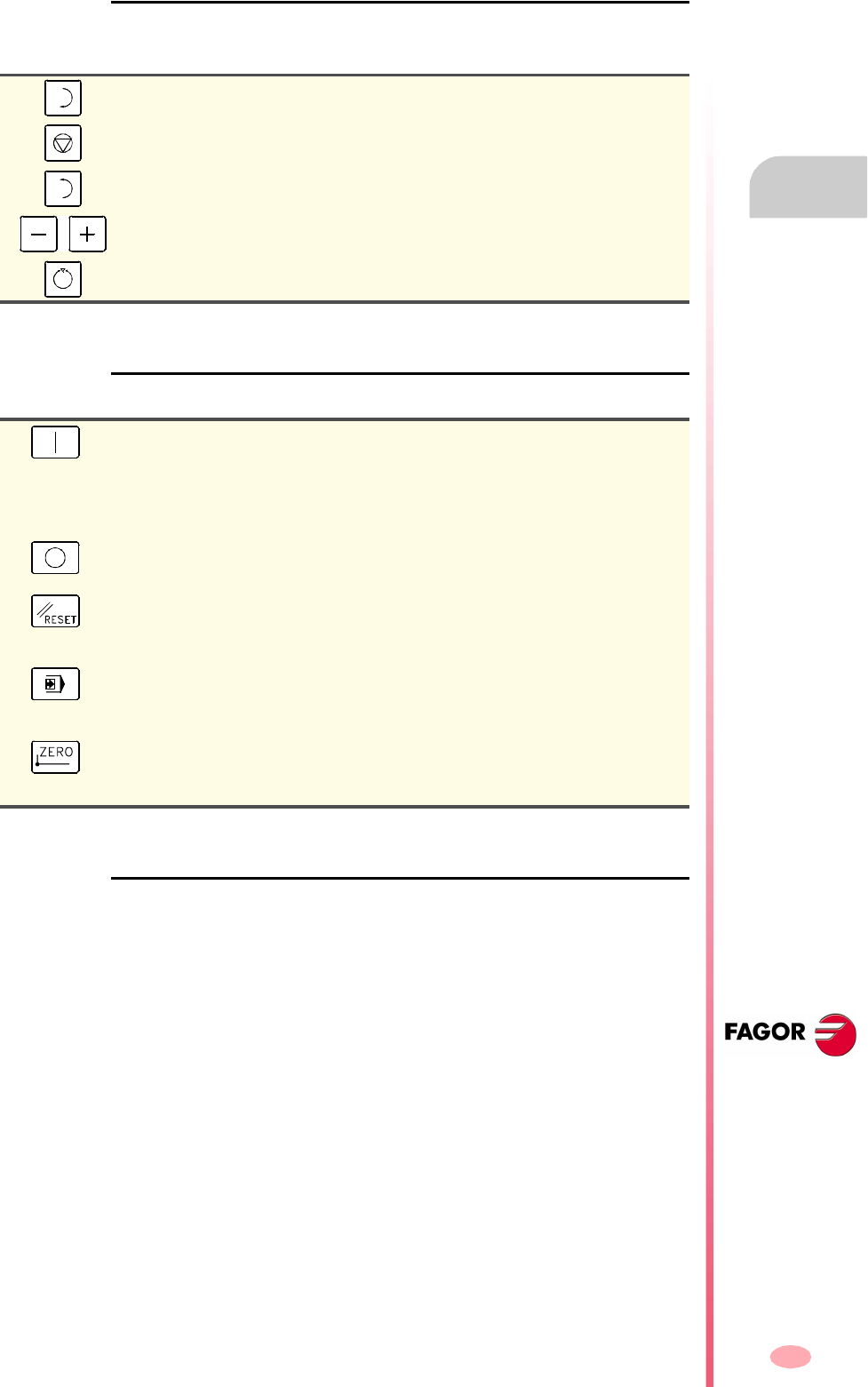
Spindle control
It is used to govern the spindle. It consists of the following keys.
Execution keys
External devices
The functions of these keys are defined by the machine manufacturer and they allow
controlling the various devices of the machine (coolant, chip remover, etc.).
Start the spindle clockwise.
To stop the spindle.
Start the spindle counterclockwise.
To vary the spindle speed percentually.
Spindle orientation.
Cycle start key.
It executes the program selected in the execution mode regardless of the active
work mode (except for MDI mode). If the program has been interrupted, it resumes
its execution.
If MDI mode is active, it executes the block just edited.
Cycle stop key.
It interrupts the execution of the program or the MDI block.
RESET key.
It initializes the system setting the initial conditions as defined by machine
parameters.
Single-block execution mode.
It selects the single block execution mode. When this mode is active, the execution
of the program is interrupted at the end of each block.
Home search.
It is used to reference (home) one or several axes at the same time using a
subroutine.
Operating manual
CNC 8070
1.
GENERAL CONCEPTS
Directory structure
(SOFT V03.0X)
10
1.4 Directory structure
The necessary files for the CNC are located in the directory C:\CNC8070 and its
relevant subdirectories.
FAGOR Version directory
This directory contains the software corresponding to the CNC version installed.
Software updates are carried out in this directory and they do not affect the contents
of directories MTB and USERS,
MTB OEM directory
This is especially directed at machine manufacturers.
This directory contains the modifications made by the machine manufacturer at the
CNC like, for example, the PLC program, machine parameters, custom settings, new
screens, integrating external applications, etc.
TMP Temporary files
This directory is used by the CNC to save the temporary files generated while
operating.
The directory contents are erased every time the CNC is turned on.
USERS User directory
It is especially directed at users.
The purpose of this directory is to provide the user with a memory space for storing
part-programs, profiles, etc. as they are generated.
UNINST Uninstall directory
This directory contains the necessary files to uninstall the software of the 8070 CNC.
To uninstall, double-click on the fimain.exe file and follow the instructions displayed
on the screen.
Do not change the contents of this directory. Only authorized personnel from
Fagor Automation may modify the contents of this directory.
Fagor Automation shall not be held responsible of the performance of this
CNC if the contents of this directory have been changed.

Operating manual
CNC 8070
GENERAL CONCEPTS
Directory structure
1.
(SOFT V03.0X)
11
1.4.1 MTB (Machine Tool Builder) directory
This is especially directed at machine manufacturers.
This directory contains the modifications made by the machine manufacturer at the
CNC like, for example, the PLC program, machine parameters, custom settings, new
screens, integrating external applications, etc.
DATA This directory contains:
•The databases for machine parameters, tables, etc. and the safety backup (in
ASCII) of those tables.
•(*.dat) files related to the machining canned cycles (cycle editor).
•The copies made for storing data after turning the CNC off (coordinates, zero
offsets, etc.)
DRIVE This directory contains the information regarding the DDSSETUP.
MMC This directory contains the CNC custom setting made by the machine builder:
•The directory "...\MMC\CONFIG", the files that may be modified using the screen
customizing tool (Fguim.exe).
•In the directory "...\MMC\IMAGES", the machine builder may include all the files
of the application regarding bitmaps, videos, icons, etc.
Initially, it will be a copy of the directory "...\FAGOR\MMC".
PLC This directory keeps the information regarding the PLC integrated by the machine
builder:
•The directory "...\PLC\LANG" contains the PLC messages and error messages
in the different languages
•The directory "...\PLC\PROJECT" contains the files that make up the PLC project
and the object file.
•The directory "...\PLC\WATCH" contains the sets saved from monitoring and the
logic analyzer.
RELEASE When the machine builder integrates his/her own application into the CNC, the
components that have been created (*.OCX files) will have to be located in this
directory.
SUB When the machine builder integrates his/her own subroutines (tool change, home
search, etc.), they will have to located in this directory.
TUNING This directory stores the configurations saved by the user in the setup assistance.

Operating manual
CNC 8070
1.
GENERAL CONCEPTS
Directory structure
(SOFT V03.0X)
12
1.4.2 USERS directory
It is especially directed at users.
The purpose of this directory is to provide the user with a memory space for storing
part-programs, profiles, etc. as they are generated.
Although the user may store these programs in any directory, they should be saved
in the directories created for this purpose in order to make it easier and faster to find
them and make safety backup copies.
POCKET This directory saves the profiles that have been created using the profile editor and
are related to the pockets of the conversational canned cycles.
PRG This directory saves the part-programs created by the user who may create new
subdirectories and store the programs in a more orderly fashion.
PROFILE This directory saves the profiles that have been created using the profile editor and
are related to conversational canned cycles.
REPORTS This directory saves the bmp files generated when printing a graphic image to a file.
It also saves the reports (prn format) generated in the Diagnosis mode.
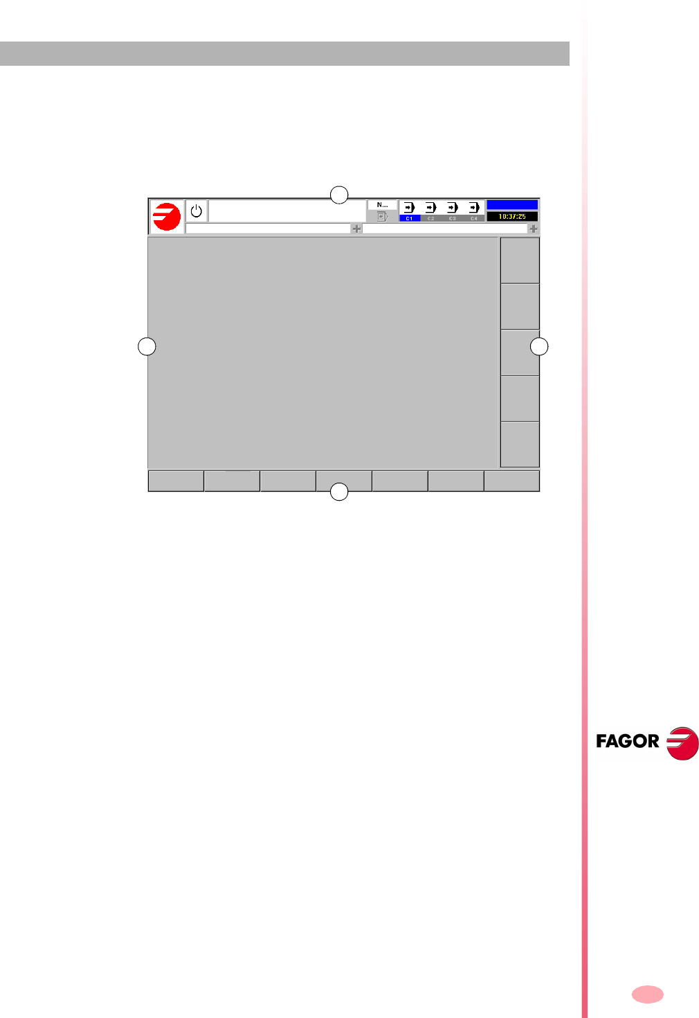
13
CNC 8070
(SOFT V03.0X)
2
HOW TO OPERATE THE CNC
2.1 Screen description
The CNC screens shows the following information:
A. General CNC-status bar.
It shows the information on the program being executed, the active operating
mode and the PLC messages. See "Detailed description of the CNC status
bar" on page 14.
B. Screen for the active work mode.
The information shown in this area depends on the active work mode (automatic,
jog, etc.). The information shown in each work mode is described in the relevant
chapter.
C. Vertical softkey menu (icons).
The menu options change depending on the active work mode. The different
options are selected using softkeys F8 through F12.
This menu may be placed either on the left or on the right of the screen.
D. Horizontal softkey menu.
The menu options change depending on the active work mode. The different
options are selected using softkeys F1 through F7.
A
B C
D
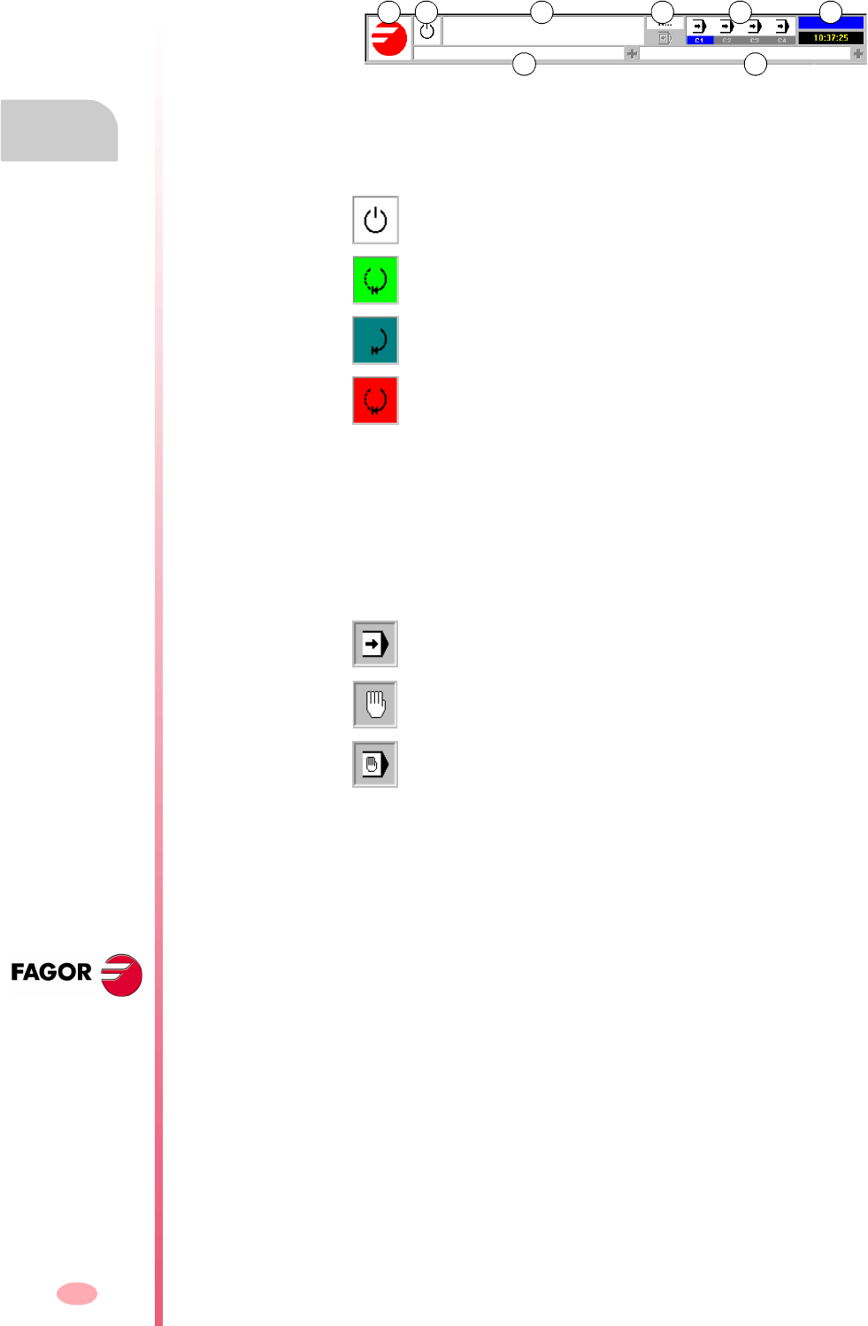
Operating manual
CNC 8070
2.
HOW TO OPERATE THE CNC
Screen description
(SOFT V03.0X)
14
2.1.1 Detailed description of the CNC status bar
The top of the screen shows the following information:
A. Icon (customizable) identifying the manufacturer.
B. Icon showing the status of the program of the active channel:
The background color will be different depending on the status of the program.
C. Program selected in the active channel for execution.
The background color will be different depending on the status of the program.
D. Number of the block in execution. The bottom icon indicates that the Single-block
execution mode is active.
E. Information about the channels.
Number of channels available and active channel (indicated in blue). Icons show
which operating mode each channel is in.
The channel synchronization window may be expanded using the [ALT]+[S] keys.
The synchronization is carried out using marks in the programs. The window
shows for each channel whether it is waiting for synchronization marks or not and
the status of those marks in the channel that originates them.
An LED of various colors of the window show the status of the synchronization marks
of each channel. On the left, the channels waiting for the marks and on top the
channels that originate them.
Programmed stopped.
Program in execution.
Background color: Green.
Program interrupted.
Background color: Dark green.
Program in error.
Background color: Red.
Execution mode.
Jog mode.
MDI mode.
White No synchronization mark expected.
Green Synchronization mark expected. The mark is set to 1 in the channel
that originates it.
Red Synchronization mark expected. The mark is set to 0 in the channel
that originates it.
A B C D E F
G H
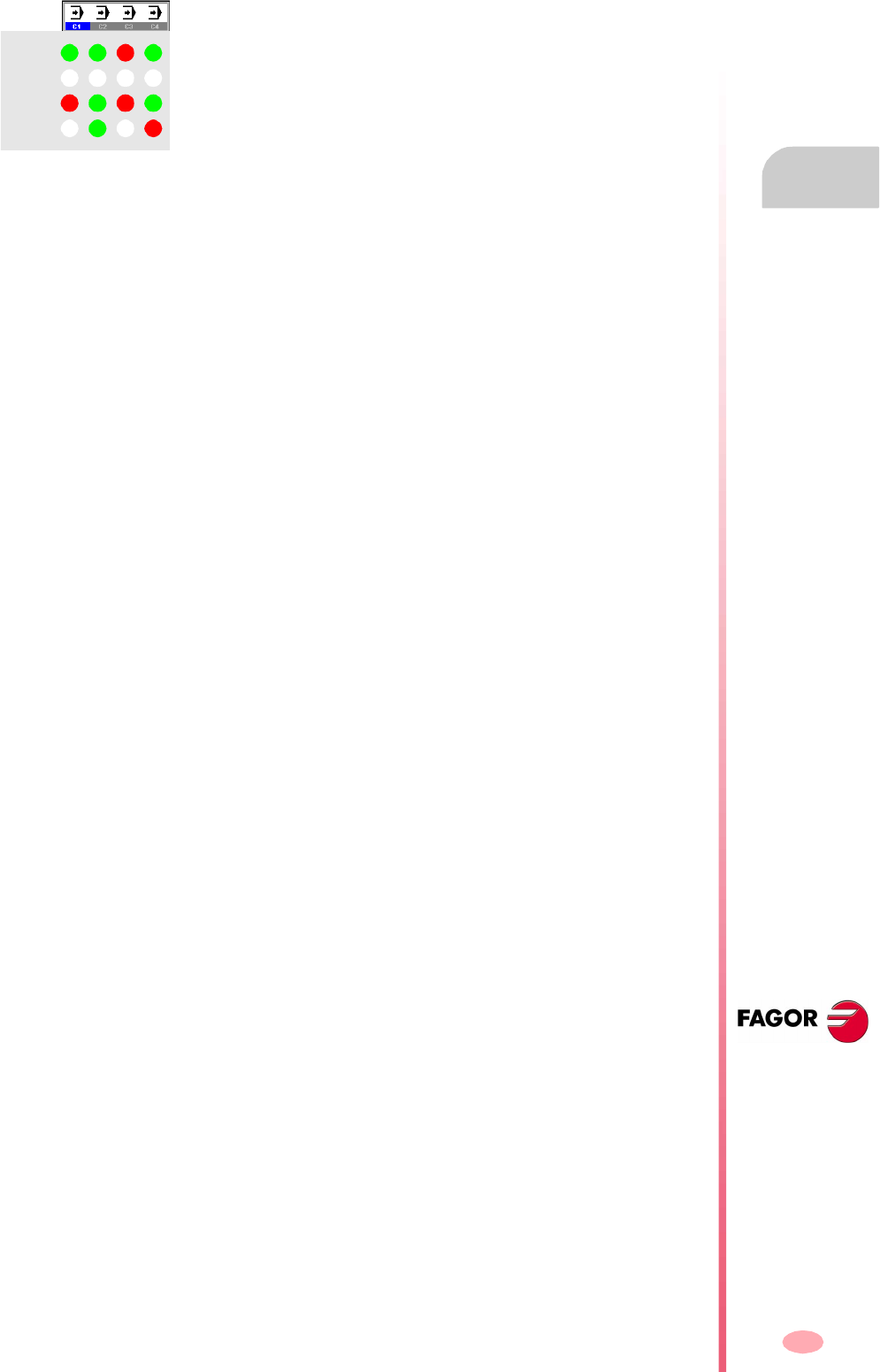
Operating manual
CNC 8070
HOW TO OPERATE THE CNC
Screen description
2.
(SOFT V03.0X)
15
F. Active work mode (automatic, manual, etc.) selected screen number and total
number of screens available.
System clock.
G. Active CNC message.
For each channel, it shows the last message activated by the program that is
running. The window shows the last message of the active channel. If there are
messages in other channels, it will highlight the "+" sign next to the message
window. To display the list of active messages, press the key combination
[CTRL]+[O].
The list of messages shows, next to each message, the channel where it is active.
H. PLC messages.
If the PLC activates two or more messages, the CNC displays the message with
the highest priority and it will show the "+" sign indicating that there are more
messages activated by the PLC. To display the list of active messages, press the
key combination [CTRL]+[M].
On the message list and next to each message, a symbol will appear to indicate
whether the message has an additional information file associated with it or not.
To display a message, select it with the cursor and press [ENTER]. If the message
has an additional information file, it will be displayed on the screen.
Channel 1 (CH1) is expecting synchronism marks from the rest of the
channels. The marks of channels 2 and 4 are set to 1. The mark of channel
3 is set to zero.
Channel 2 is not expecting any synchronism mark.
(In the graphic, the white LED's are identified with the letter -W-, the green
ones with the letter -G- and the red ones with the letter -R-).
CH1
CH2
CH3
CH4
WWWW
WW
G
G
GGG
GR
R
R
R
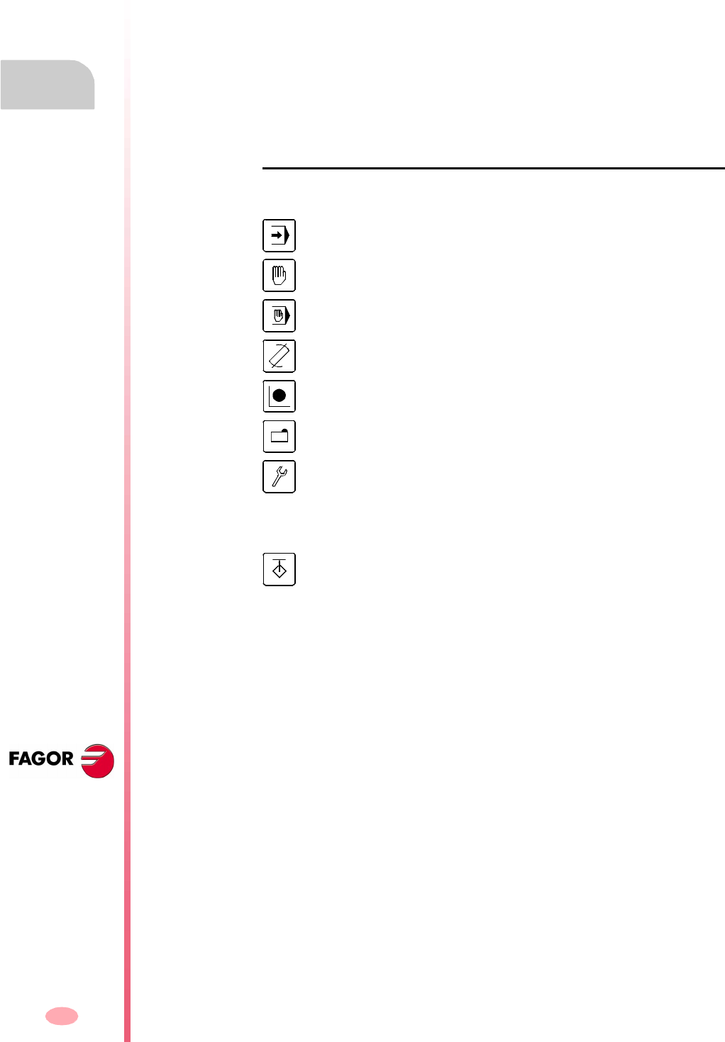
Operating manual
CNC 8070
2.
HOW TO OPERATE THE CNC
Operating modes
(SOFT V03.0X)
16
2.2 Operating modes
2.2.1 How to access to the operating modes
The CNC operating modes may be accessed from the keyboard or from the task
window that is displayed with the key combination [CTRL]+[A].
Each operating mode may consist of several screens or pages. Switching between
the different screens is done by pressing the access key for that operating mode.
Every time it is pressed, it displays the next screen. The screen selection is rotary
in such a way that when pressing this key on the last screen, it shows the first one.
Accessing the operating modes from the keyboard
The following operating modes may be accessed from the keyboard.
Also, the keyboard has a special key that may be configured by the machine
manufacturer to access their specific operating modes.
Automatic mode.
Jog mode.
MDI mode.
Editing - simulation mode.
User tables.
Tool and magazine table.
Utilities mode.
•Machine parameters.
•PLC.
•Diagnosis mode.
•Setup assistance.
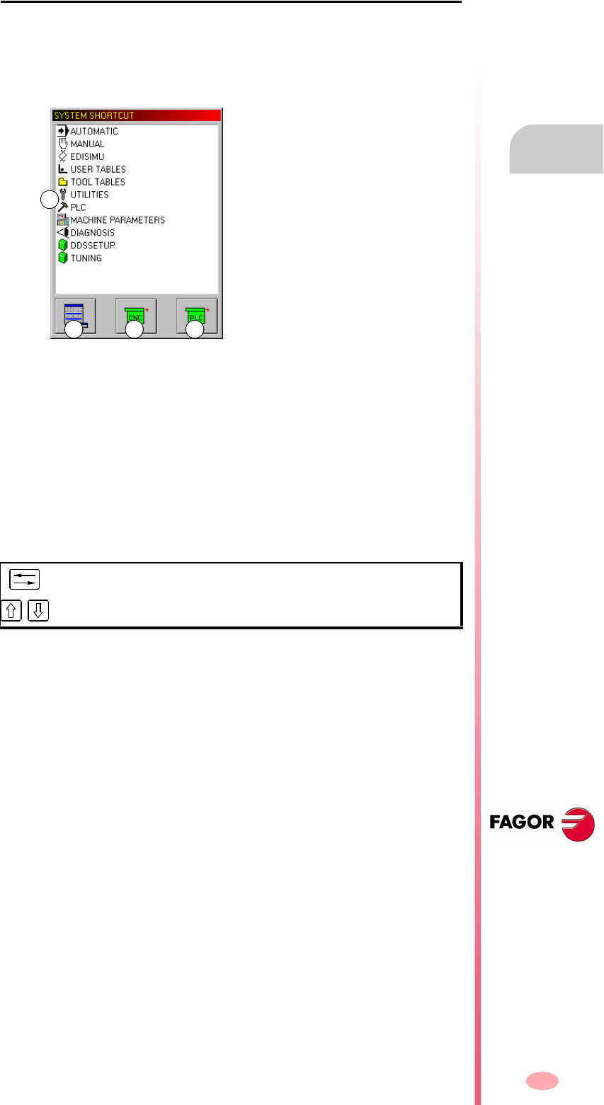
Operating manual
CNC 8070
HOW TO OPERATE THE CNC
Operating modes
2.
(SOFT V03.0X)
17
Task window
All CNC operating modes may be accessed from the task window. Use the [CTRL]
+ [A] keys to open the task window. Press [ESC] to close the window without making
a selection.
The task window looks like this.
A. Available operating modes
B. Shows or hides virtual jog panel.
Same as using the [CTRL]+[J] key combination.
C. Expands the list of active CNC messages.
Same as using the [CTRL]+[O] key combination.
D. Expands the list of active PLC messages.
Same as using the [CTRL]+[M] key combination.
Moving around in the task window
Besides the mouse, the following keys may be used.
After selecting an operating mode or one of the lower buttons, press [ENTER] to
activate it.
To move the cursor thru the elements of the window.
Moves the cursor over the list of operating modes.
A
CB D

Operating manual
CNC 8070
2.
HOW TO OPERATE THE CNC
Operating modes
(SOFT V03.0X)
18
2.2.2 Description of the various operating modes
Automatic mode
It is used to execute part-programs in automatic or single-block mode.
While executing a part-program, any other operating mode may also be accessed
(except "MANUAL" and "MDI") without interrupting the execution of the program. This
way, a program may be edited while another one is running (background editing). The
running program cannot be edited.
Manual (jog) mode
It is used to control the machine movements manually using the keys of the operator
panel, perform a home search, set the part zero, etc.
Editing - simulation mode
It is used for editing and simulating part-programs even while running another part-
program.
MDI mode
It is used for editing and executing blocks in ISO code or in high-level language.
User tables
It is used for manipulating the CNC tables regarding part-programs (zero offsets,
fixtures and arithmetic parameters).
Tool and magazine table
It is used to edit CNC tables regarding the tools and the tool magazine.
Utilities mode
It is used to handle CNC part-programs (copy, delete, rename, etc.).
A password may also be set to access the various operating modes.
Likewise, it offers the possibility to do a backup or a restore of the desired part of the
disk.

Operating manual
CNC 8070
HOW TO OPERATE THE CNC
Operating modes
2.
(SOFT V03.0X)
19
PLC
It is used to operate with the PLC (edit a program, monitor, change the status of its
variables, etc.).
Machine parameter table
It is used for setting the machine parameters to adapt the CNC to the machine.
Tuning mode. Setup assistance
For faster and easier machine setup.
This mode offers the axis adjustment guide, the circle test, the oscilloscope and the
Bode graphs.
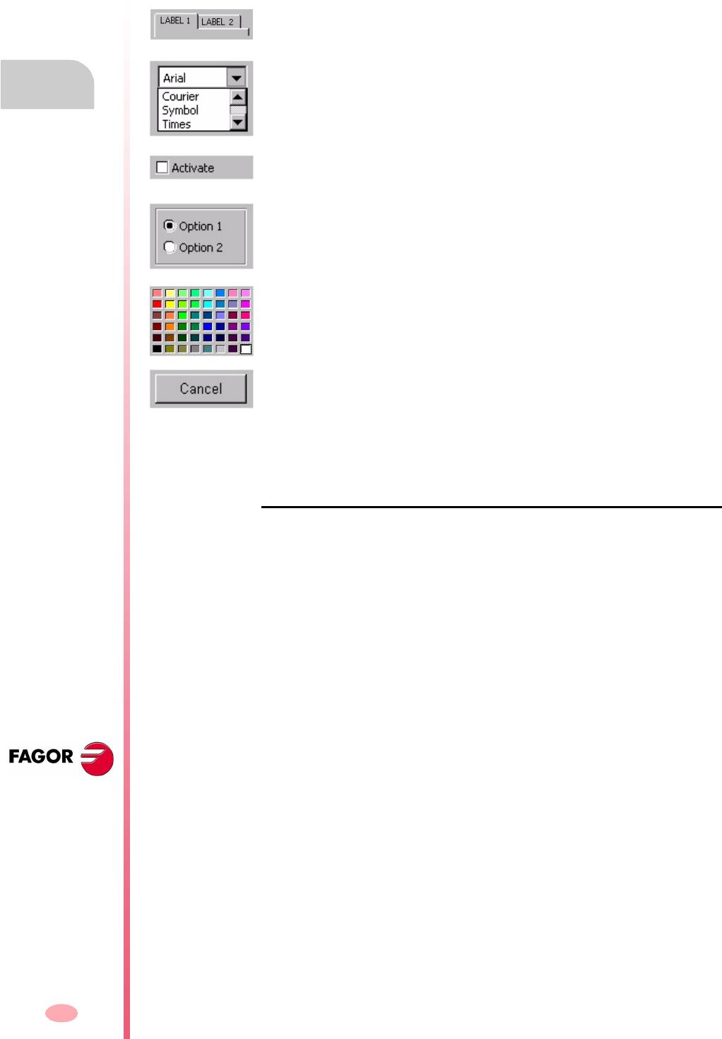
Operating manual
CNC 8070
2.
HOW TO OPERATE THE CNC
Dialog boxes
(SOFT V03.0X)
20
2.3 Dialog boxes
The dialog boxes consist of the following elements. All the actions may be carried out
with the mouse or via keyboard.
Using the keyboard
The data of the dialog boxes are defined via keyboard as follows.
•Using the [CTRL]+[TAB] combination, it is possible to select different panels of
the dialog box.
•The [TAB] key moves the cursor through the elements of the box.
•The [SPACE] key activates the selection boxes, selects an options and selects
a color from the color pallet.
•The [ENTER] key presses the button that is selected.
•The [ESC] key closes the dialog box without accepting the changes.
•On the drop lists, the desired option may be selected using the keys on the
keyboard.
•The arrow keys [§][¨][©][ª] move the cursor over the color pallet and over the
options of a list.
•Selection panels.
It selects among the different option groups within the same dialog box.
•Drop list.
It selects an option from a list. Clicking on the right icon, the list expands.
•Selection box.
It activates an option.
•Option selection.
It selects an option from a group. Selecting one cancels the previous one.
•Color pallet.
Select a color.
•Selection buttons.
They access a group of options or close the dialog box.
After making the changes, the dialog boxes are closed using one of the buttons
that let you accept or reject the changes made.

Operating manual
CNC 8070
HOW TO OPERATE THE CNC
Windows for warnings and errors
2.
(SOFT V03.0X)
21
2.4 Windows for warnings and errors
When an error occurs, the CNC will display a window describing the cause of the error.
There are three types of errors. The top of the window shows the category and it will
have a different color depending on the type of error it shows.
WARNING Green window.
ERROR Red window.
FATAL ERROR Purple window.
When several warnings and/or errors occur simultaneously, they are displayed from
the one with the lowest priority to the one with the highest priority. The top right side
of the window shows the priority level of the message. A down arrow indicates that
there are errors with lower priority and an up arrow indicates that there are errors with
higher priority. The operator can toggle the different active errors using the [©][ª]
keys.
WARNING
It is just that, a warning.
They do not stop part-program execution and the warning window may be closed by
pressing [ESC].
ERROR
It may be a syntax error in a program, PLC generated errors, etc. They are errors that
must be corrected.
They interrupt the execution of the program. Although the window displaying them
may be closed by pressing [ESC], it does not mean that the error status has been
taken care of. To do that, press [RESET]. After pressing [RESET] the CNC assumes
the initial conditions set by the machine manufacturer with the machine parameters.
While the error window is active, no other action will be possible but removing it (it
is not possible to change operating modes).
Refer to the error solving manual for a detailed description of the cause of the error
and its possible solutions.
FATAL ERROR
They are errors that force the operator to turn the CNC off.
If the error persists, contact the Service Department at Fagor Automation.
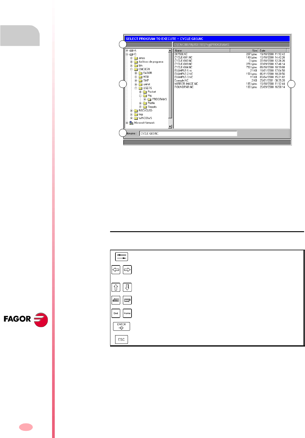
Operating manual
CNC 8070
2.
HOW TO OPERATE THE CNC
File selection window
(SOFT V03.0X)
22
2.5 File selection window
The file selection window is common to all operating modes. This window is displayed
when, from an operating mode, the operator selects the option to open, save or import
a file, open or load a table, etc.
From this window, it is possible to either select an existing file or create a new one.
A new file may be created only when it is a valid action. Depending on the operating
mode it is accessed from, the list will only show the proper files.
A. Type of file to be selected.
B. Folders accessible from the CNC, as well as how they are structured. It shows
all the elements accessible from the CNC, such as the hard disk, floppy disk drive,
CD-ROM unit, etc.
C. Files contained in the selected folder.
D. Area to define the name of the new files. A file can also be selected when knowing
its name.
Move around in the window
Besides the mouse, the following keys may be used.
It switches the window focus.
With the focus on a folder, it closes and opens the submenu of
folders.
To move the focus through the elements of the window.
To move the focus page by page.
To move the focus to the beginning or end of the list.
Opens the selected file.
To cancel the selection and close the program listing.
D
B C
A

Operating manual
CNC 8070
HOW TO OPERATE THE CNC
File selection window
2.
(SOFT V03.0X)
23
To select a file from the list
To make searching easier, the file list may be sorted according to different criteria.
See "Sorting the list of files" on page 23.
A file may be selected from the list:
1. Select the folder that contains the program.
2. Select the file from the list or write its name in the bottom window.
3. Press [ENTER] to accept the selection.
Pressing [ESC] cancels the operation at any time and closes the window.
How to search an element from the list
An element (folder or file) may be selected from the list by moving the cursor to the
desired element or using an alphanumeric keyboard. Pressing a key will select the
first element from the list starting with that letter or number. Pressing it again will select
the second one and so on.
The files can also be selected using the "Find file" softkey. See "File search" on page
24.
Creating a new file
To create a new file:
1. Select the destination folder for the file.
2. Write the file name at the bottom window.
3. Press [ENTER] to confirm the action.
Pressing [ESC] cancels the operation at any time and closes the window.
Sorting the list of files
The file list may be ordered alphabetically, by size or by date.
•When using a mouse, select the column header with the pointer. Every time the
same header is selected, it toggles the sorting criteria from ascending to
descending and vice versa.
•From the softkey menu. Every time the same softkey is selected, the CNC toggles
the sorting criteria from ascending to descending and vice versa.
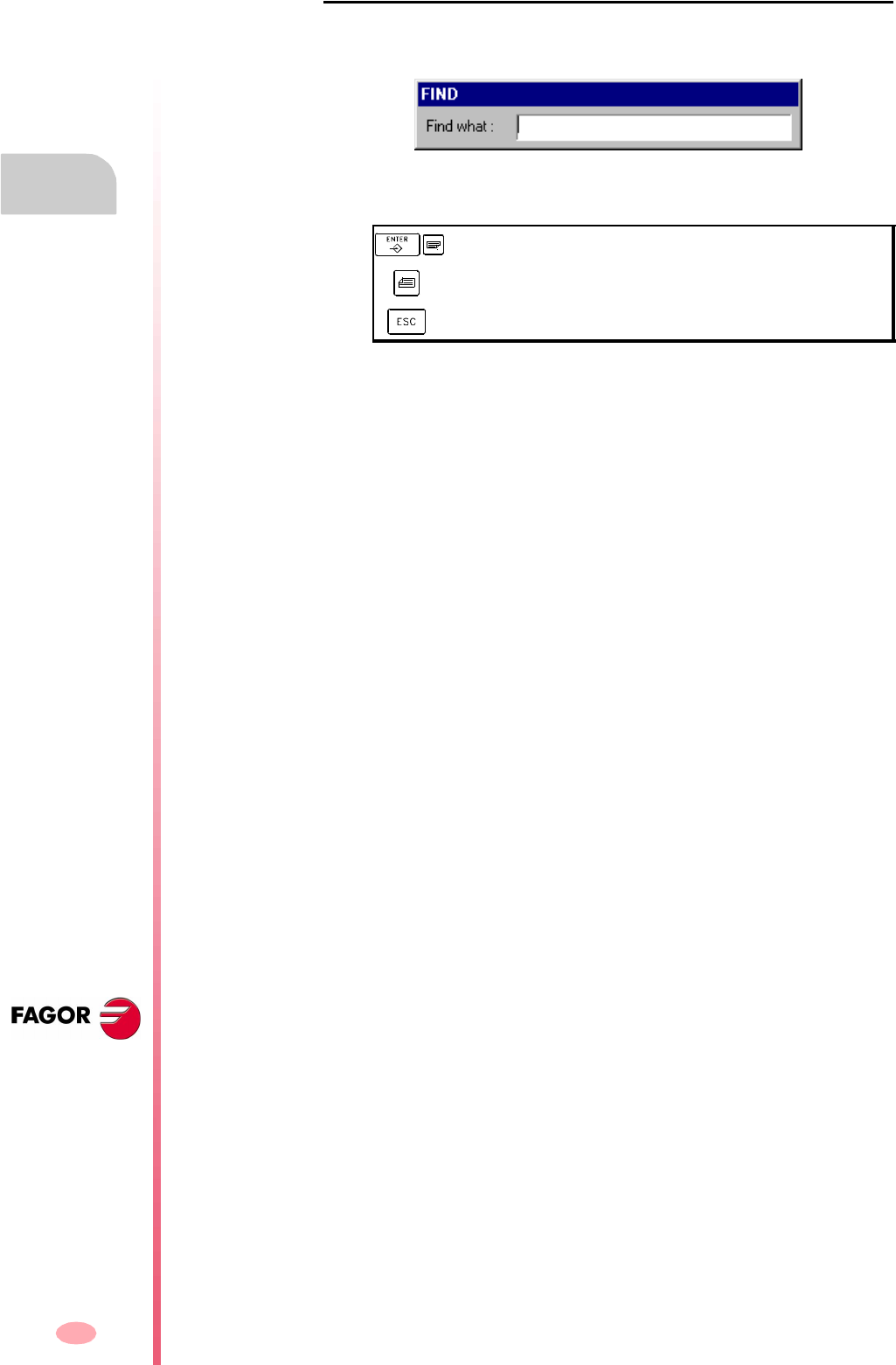
Operating manual
CNC 8070
2.
HOW TO OPERATE THE CNC
File selection window
(SOFT V03.0X)
24
File search
It is used to look for files whose names contain a particular character string. When
selecting this option, the CNC shows a dialog box requesting the text to be found.
The programs are searched one by one. It may be searched using either the softkey
menu or the following keys.
When defining a search, the softkey menu shows the "Next" and "Previous" options.
•Search next, it looks for the next program (in descending order).
•Search previous, it looks for the previous program (in ascending order).
Depending on how the search is carried out, the focus goes to the last file found,
whose name also appears at the top of the window. To end the search, press [ESC].
To search for the next program (in descending order).
To search for the previous program (in ascending order).
To end the search and close the dialog box.
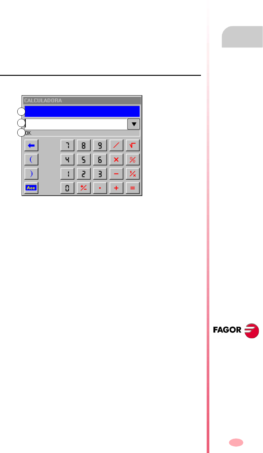
Operating manual
CNC 8070
HOW TO OPERATE THE CNC
Calculator
2.
(SOFT V03.0X)
25
2.6 Calculator
The calculator may be accessed from any task window or directly using the key
combination [CTRL]+[K]. Press [ESC] to close the calculator.
The calculator may be accessed from any operating mode. When accessing from an
editable element, the result displayed by the calculator may be inserted. An editable
element is any element that may have a focus or cursor, such as the program editor,
tables, editable data, etc.
To insert the result, press the [INS] key. It closes the calculator and inserts the result
in the position that the cursor had when accessing the calculator.
The calculator looks like this
The calculator looks like this.
A. Results window. It shows the result of the expression after accepting it with the
[ENTER] key.
This value may be recovered with the "Acc" button so it can be used in later
calculations.
B. Editing window. It shows the expression being defined. The expression may
consist of one or several operations that may be defined directly from the keyboard
or with the softkey menu options.
It saves the list of the last operations.
C. Explorer window. It shows, at all times, the result from evaluating the expression
being defined. When selecting a portion of the expression at the edit window, it
will show the result from evaluating that portion.
The result from evaluating the expression may be:
Operations history
The expressions already accepted become part of the history and may be displayed
using the relevant keys [©][ª]. After selecting an expression from the window, press
the [ENTER] key to recover it. The [ESC] key closes the history window.
OK: ########### Numeric.
OK: 1.#INF Infinite.
Error: <> Syntax error.
Wrong expression Wrong expression.
C
A
B
Operating manual
CNC 8070
2.
HOW TO OPERATE THE CNC
Calculator
(SOFT V03.0X)
26
Softkey menu
The softkey menu shows all the available operations. The expressions may be edited
using either the softkey menu or the mouse with the calculator keys.
Work units
The result of the operations may be given in various units. Use the following icons
to change the units. It highlights the units currently selected.
Hexadecimal ($), decimal (D) or binary (B) units.
Units in degrees or radians.

Operating manual
CNC 8070
HOW TO OPERATE THE CNC
Calculator
2.
(SOFT V03.0X)
27
2.6.1 Defining expressions
An expression may consist of one or more operations. Each one of them may be
defined by any valid combination of variables, constants, functions and operations.
Press [ENTER] To accept the expression entered and calculate the value.
Quick parenthesis insertion
To place a portion of an expression between parenthesis, select the portion and press
one of the parenthesis keys "(" or ")".
If while a portion of the expression is selected, an operation key is pressed, the
selection will appear between parenthesis and it will be preceded by the operation
just defined.
Example: Having the expression "1+1/X+1/(X+1)+1". When selecting the
"1/(X+1)+1" portion and pressing the "SIN" option, the expression will become
"1+1/X+Sin(1/(X+1)+1)".
Variables for the calculator
Up to 26 variables (from "A" to "Z", except "Ñ",) may be used to store numeric values
and use them later.
Assigning a value to a variable: A = 34.234
Reference to a variable: Sin(A/2)
A single expression may contain both assignment and reference operations. Use the
":" character as separator.
A=34.234:Sin(A/2) is the same as Sin((A=34.234)/2)
Constants
The following constants are available and they may be accessed from the softkey
menu.
Various operations
In the following examples, the "x" and "y" values indicate any valid combination of
constants, variables or expressions.
Binary operations.
The values of the calculator variables "A" - "Z" are independent from the values
of local parameters "A" - "Z" (also called P0 through P25).
i
PI Value of pi (3.14159...)
MM -> INCHES mm/inch conversion factor.
INCHES ->MM inch/mm conversion factor.
AND Binary AND 1001 AND 1010 = 1000
OR Binary OR 1001 OR 1010 = 1011
XOR Exclusive OR 1001 XOR 1010 = 0011
NOT Inverse NOT 101 = 1···1010
Operating manual
CNC 8070
2.
HOW TO OPERATE THE CNC
Calculator
(SOFT V03.0X)
28
Arithmetic operations.
Trigonometric operations.
Conversion functions.
Extended functions
INTEGRAL function
It returns as result, the integral defined by the function between the limits defined by
the "A" and "B" variables.
The precision of the result depends on the "N" variable, that indicates the number of
intervals used to divide the function in order to calculate the integral. If "N" is less than
or equal to zero, it will be ignored and the number of intervals will be 100. If "N" is
greater than 500000, the intervals will be 500000.
ZERO function
It returns as result, the value that makes the function to be zero. Since there may be
several values satisfying this condition, the result will depend on the initial value of
the exploration defined with the "A" variable.
The precision of the result depends on the "N" variable that indicates the number of
iterations of the resolution algorithm. If "N" is less than or equal to zero, it will be
ignored and the number of iterations will be 100. If "N" is greater than 500000, the
intervals will be 500000.
x + yAdd
x - ySubtract
x *yMultiply
x / yDivide
x % yPercentage 10%50 = 5
x ^ yPower 2^3 = 2 ∗ 2 ∗ 2 = 8
x!Factor 3! = 3 ∗ 2 ∗ 1 = 6
SIN(x)Sine SIN 30 = 0.5
COS(x)Cosine COS 60 = 0.5
TAN (x)Tangent TAN 45 = 1
INV SIN(x)Arc-sine InvSin 0.5 = 30
INV COS(x)Arc-cosine InvCos 0.5 = 60
INV TAN(x)Arc-tangent InvTan 1 = 45
MM -> INCHES It converts from millimeters to inches.
INCHES ->MM It converts from inches to millimeters.
ABS(x)Absolute value.
INT(x)Integer.
SQRT xSquare root SQRT 16
LN xNeperian log LN 100
LOG xDecimal log. LOG 100
e ^ x"e" function InvLn 3
10 ^ xDecimal exponent InvLog 50
INTEGRAL xIt calculates the
integral
N=100:A=1:B=5:Integral(x+2)
ZERO xFunction zero N=100:E=1e-10:A=5:Zero(x^2)

Operating manual
CNC 8070
HOW TO OPERATE THE CNC
Calculator
2.
(SOFT V03.0X)
29
The "E" variables define the error allowed so the result of the function with the
calculated value is smaller than "E". This variable is useful when not knowing what
value to assign to "N". In that case, it is recommended to assign to "N" a very large
value and to "E" the error allowed.
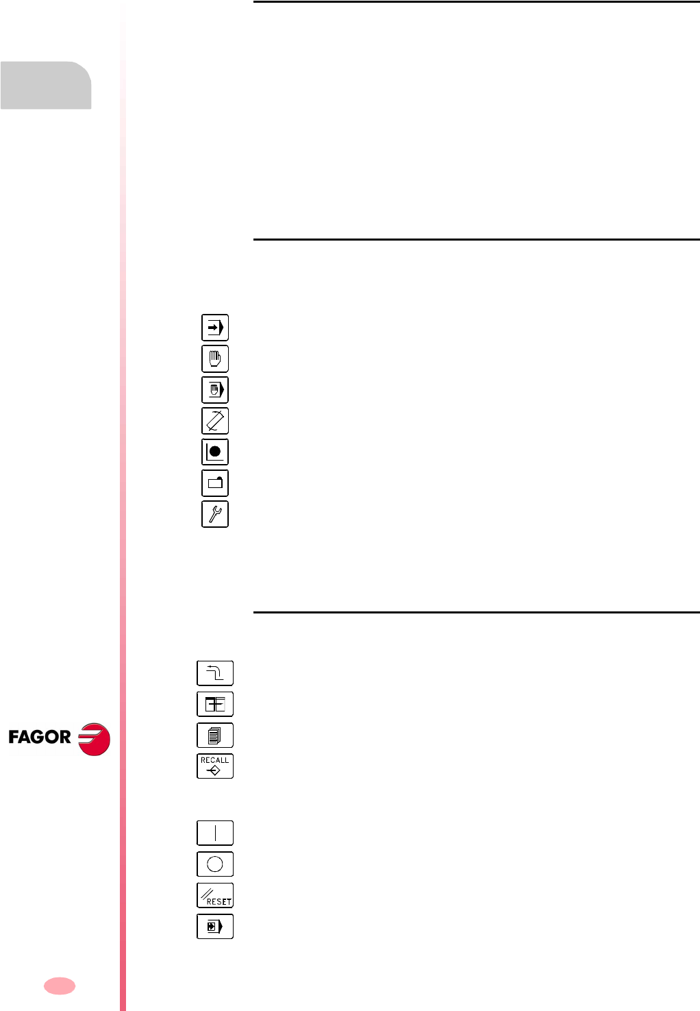
Operating manual
CNC 8070
2.
HOW TO OPERATE THE CNC
Keyboard shortcuts
(SOFT V03.0X)
30
2.7 Keyboard shortcuts
Operations at the interface
To perform different operations with the CNC.
Work modes
To select the CNC operating modes.
CNC keys
Same as pressing the following CNC keys
Same as pressing the following keys of the operator panel.
[CTRL] + [W] Minimize/Maximize the CNC.
[CTRL] + [J] Show / hide the virtual operator panel.
[CTRL] + [M] Show / hide the PLC message list.
[CTRL] + [O] Show / hide the CNC message list.
[ALT] + [F4] Turn the CNC off.
[CTRL] + [A] To show the task window.
[CTRL] + [F6] Automatic mode.
[CTRL] + [F7] Jog mode.
[CTRL] + [F8] MDI mode.
[CTRL] + [F9] Editing - simulation mode.
[CTRL] + [F10] User tables.
[CTRL] + [F11] Tool and magazine table.
[CTRL] + [F12] Utilities mode.
[CTRL] + [K] Calculator.
[CTRL]+[F1] Previous menu.
[CTRL]+[F2] Switch window.
[CTRL]+[F3] Switch screens.
[CTRL]+[F5] [RECALL] key.
[CTRL]+[S] [START] key.
[CTRL]+[P] [STOP] key.
[CTRL]+[R] [RESET] key.
[CTRL]+[B] "Single block" execution key.

Operating manual
CNC 8070
HOW TO OPERATE THE CNC
Keyboard shortcuts
2.
(SOFT V03.0X)
31
Program editor
Keyboard shortcuts available at the part-program and PLC program editor.
[CTRL]+[TAB] Toggle between the editor and the error window.
[CTRL]+[C] Copy the selected text onto the clipboard.
[CTRL]+[X] Cut the selected text.
[CTRL]+[V] Paste the selected text.
[CTRL]+[Z] Undo the last change.
[CTRL]+[G] Save the program/Recover the original program.
[CTRL]+[HOME] Move the cursor to the beginning of the program.
[CTRL]+[END] Move the program to the end of the program.

Operating manual
CNC 8070
2.
HOW TO OPERATE THE CNC
Keyboard shortcuts
(SOFT V03.0X)
32
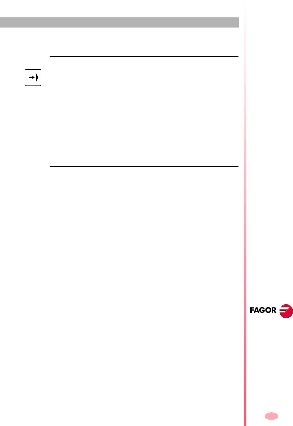
33
CNC 8070
(SOFT V03.0X)
3
AUTOMATIC MODE
Automatic mode selection
This work mode may be accessed from any channel and even from several channels
at the same time. A different program may be executed in each channel.
From the automatic mode, and even while a program is in execution, it is possible to
access another work mode except the JOG mode and the MDI mode. If program
execution has been interrupted (either because it is being executed in "single block"
mode or because the [STOP] key has been pressed), the CNC cancels the execution
of the program and goes into jog mode.
Operations in automatic mode
The following operations are possible in this work mode:
•Select and execute a part-program.
The execution may be carried out in -automatic- mode or in -single block- mode.
•Set the execution conditions (first and last blocks) before executing the program.
•Searching a block.
Recover the history of a program up to a particular block and then resume program
execution from that block.
•Display various data related to axes position.
(Command, position referred to part zero or to home, following error, etc.).
•Display a graphic representation of the program being executed.
•Perform a tool inspection while executing the program.
The automatic mode may be selected from any other operating mode by pressing
its relevant key.

Operating manual
CNC 8070
3.
AUTOMATIC MODE
Displaying the automatic mode
(SOFT V03.0X)
34
3.1 Displaying the automatic mode
When this operating mode is active, it will be indicated at the top right side of the
general status bar.
This mode may be displayed with several screens. The current screen and the total
number of available screens are shown at the upper right hand side of the general
status bar.
Switching between the different screens is done by pressing the automatic mode
accessing key. The screen selection is rotary in such a way that when pressing this
key on the last screen, it shows the first one of the operating mode.
Standard configuration
The standard configuration of this work mode, described in this manual corresponds
to the one supplied by Fagor. In some cases, the manual shows a sample screen,
instead of that of the CNC in order to make it easier to understand.
These screens may be customized by the machine manufacturer changing its
contents as well as its appearance. They may also remove certain screens or add
some of their own.
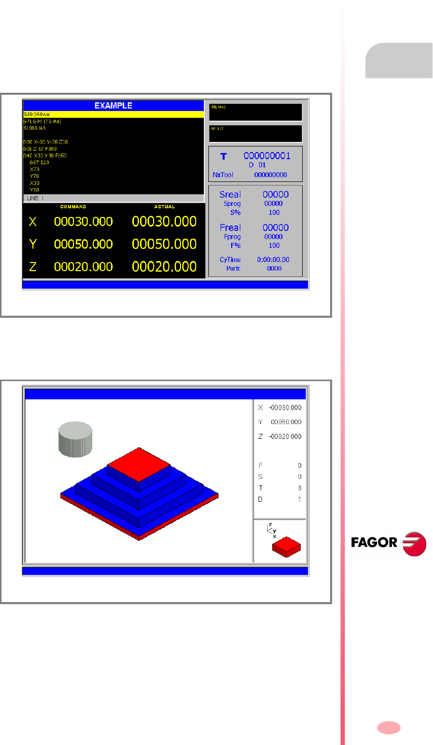
Operating manual
CNC 8070
AUTOMATIC MODE
Displaying the automatic mode
3.
(SOFT V03.0X)
35
3.1.1 Description of the screens
As mentioned earlier, the automatic mode may consist of one or several of the
following screens (later sections of this chapter describe each one in further detail).
Data screen
They show execution related data: axis position, "M" and "G" function history, active
tool and tool offset, spindle speed and axis feedrate.
When this screens shows a window with the program selected for execution, it will
be possible to select the execution starting and ending conditions as well as to recover
the program history up to a particular block.
Graphic screen
It shows a graphic representation of the program during execution. It also allows
taking measurements on the graphics.
Information on program execution.
Graphic representation of the execution of the program.
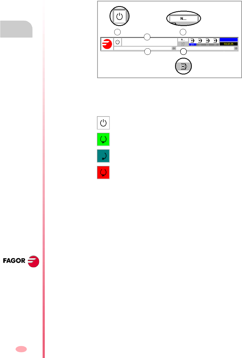
Operating manual
CNC 8070
3.
AUTOMATIC MODE
Displaying the automatic mode
(SOFT V03.0X)
36
3.1.2 Description of the general status bar
The general status bar shows the following information associated with the automatic
mode:
A. Program selected in the active channel for execution.
The background color of the window will be different depending on the program
status.
B. Icon showing the status of the program of the active channel:
The background color will be different depending on the status of the program.
C. Number of the block in execution.
D. Active CNC message.
For each channel, it shows the last message activated by the program that is
running. The window shows the last message of the active channel. If there are
messages in other channels, it will highlight the "+" sign next to the message
window. To display the list of active messages, press the key combination
[CTRL]+[O].
The list of messages shows, next to each message, the channel where it is active.
E. Icon that indicates that the "Single-block" execution mode is active. This execution
mode is selected from the operator panel.
Program waiting to be executed.
Background color: White.
Program in execution.
Background color: Green.
Program interrupted.
Background color: Dark green.
Program in error.
Background color: Red.
A
B C
D E
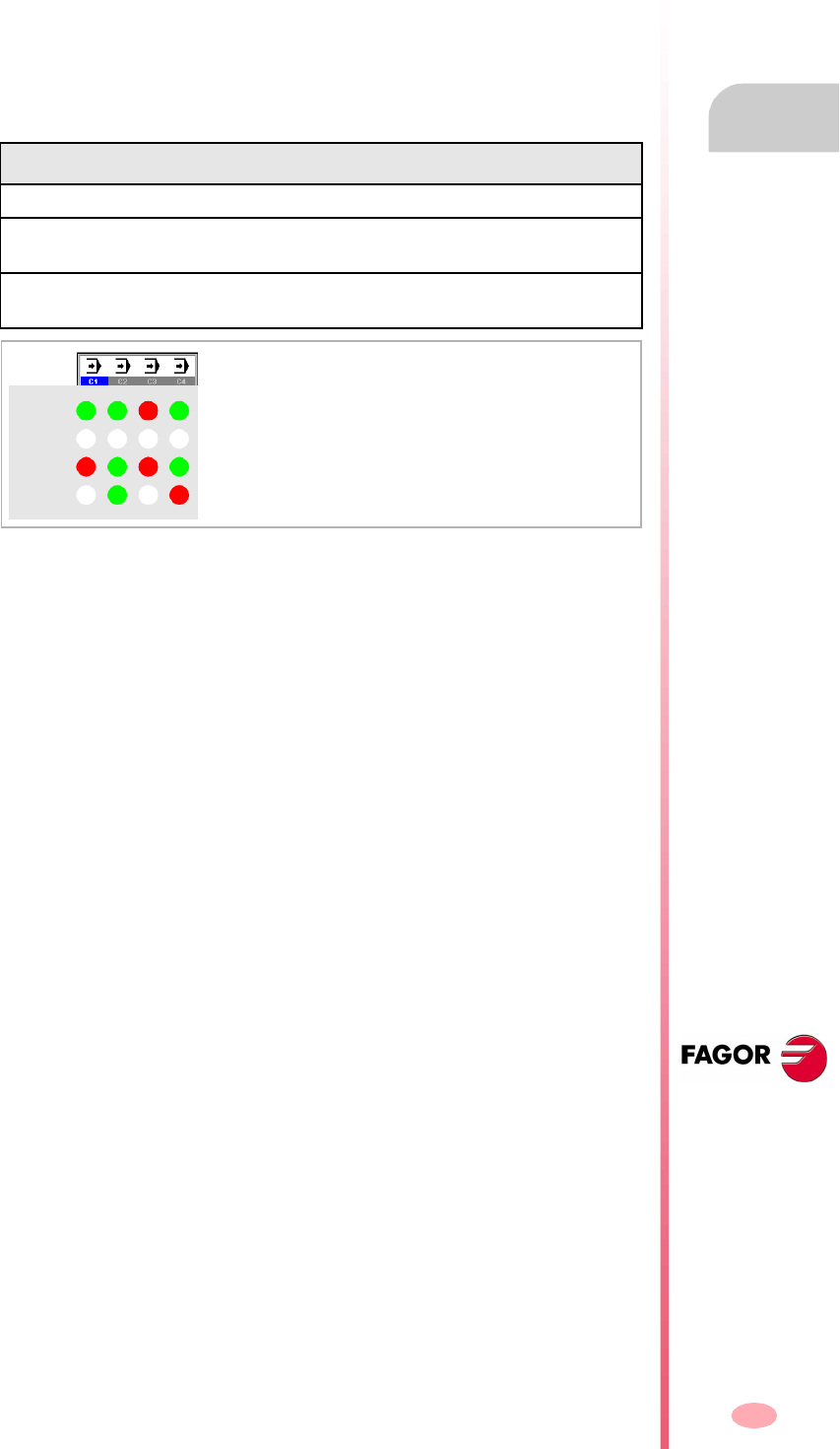
Operating manual
CNC 8070
AUTOMATIC MODE
Displaying the automatic mode
3.
(SOFT V03.0X)
37
3.1.3 Channel synchronization window
The channel synchronization window is available in all work modes. This window may
be expanded using the key combination [ALT]+[S]. The synchronization is carried out
using marks in the programs. The window shows for each channel whether it is waiting
for synchronization marks or not and the status of those marks in the channel that
originates them.
The different color LED's of the window show the status of the synchronization marks
of each channel. On the left, the channels waiting for the marks and on top the
channels that originate them.
The previous graph shows for example:
•Channel 1 (CH1) is expecting synchronism marks from the rest of the channels.
The marks of channels 2 and 4 are set to ·1·. The mark of channel 3 is set to ·0·.
•Channel 2 (CH2) is not expecting any synchronism mark.
Led Meaning
White No synchronization mark expected.
Green Synchronization mark expected. The mark is set to ·1· in the channel
that originates it.
Red Synchronization mark expected. The mark is set to ·0· in the channel
that originates it.
CH1
CH2
CH3
CH4
WWWW
WWG
G
GGG
GR
R
R
R
(In the graphic, the white LED's are identified
with the letter -W-, the green ones with the letter
-G- and the red ones with the letter -R-).
Operating manual
CNC 8070
3.
AUTOMATIC MODE
Displaying the automatic mode
(SOFT V03.0X)
38
3.1.4 Icon description (vertical softkeys)
The icon menu offers all the icons associated with this operating mode regardless
of the active screen.
The icons are activated with their associated softkey (F8 to F12).
List of icons
Program selection.
It selects a program for execution.
Begin tool inspection.
(This icon is only available when program execution is interrupted).
To begin tool inspection in order to check its condition.
While tool inspection is active, the axes may be jogged and the spindle may be started
or stopped.
End tool inspection
(This icon is only available when tool inspection is active).
It ends tool inspection.
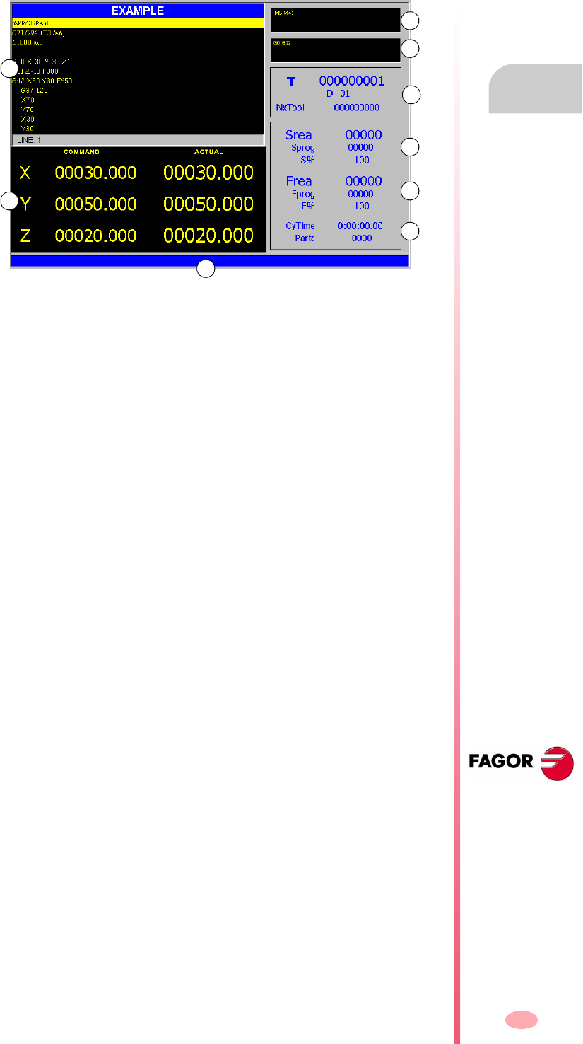
Operating manual
CNC 8070
AUTOMATIC MODE
Data screen
3.
(SOFT V03.0X)
39
3.2 Data screen
A typical screen of the automatic mode can show the following information:
A. Program window. It shows data on the program selected for execution and lets
selecting the initial and final execution blocks. It shows the following data.
•Name of the program or global subroutine, called upon from the program, that
is being executed.
•Blocks of the program or subroutine being executed. During execution, the
cursor shows the block being executed.
When accessing the automatic mode and after finishing the execution of the
program, it shows the portion of the main program even if there are local
subroutines defined in the program.
•Line of the program where the cursor is.
B. Information related to the position of the axes. In the screen configuration supplied
by Fagor, the data displayed will be different on each screen. Displaying the
following information is the most typical.
•The programmed coordinate, in other words, the target position.
•The current position of the axes referred to part zero or machine reference
zero (home) being this position referred to the tip of the tool or to its base.
•The following error (axis lag).
C. Active "M" functions.
D. Active "G" functions and high-level commands.
E. Tool related information.
Number of the tool "T" that is currently selected, currently active tool offset "D"
associated with the tool and next tool "Nextool" to be loaded into the spindle.
F. Information related to the spindle speed "S".
"Sreal" Actual spindle speed.
"Sprog" Programmed speed.
"S%" Percentage of speed override being applied on to the programmed
value.
Depending on the active screen, it will also show the spindle position "SPOS" and
its following error "SFWE".
A
B
C
D
E
F
G
H
I

Operating manual
CNC 8070
3.
AUTOMATIC MODE
Data screen
(SOFT V03.0X)
40
G. Information related to the feedrate "F" of the axes:
"Freal" Actual feedrate of the axes.
"Fprog" Programmed feedrate.
"F%" Percentage of feedrate override being applied on to the
programmed value.
H. Execution (cycle) time "CyTime" of the program and number of parts made
"Partc".
I. CNC messages.
Softkey menus
When selecting the program screen on the softkey menus, the options associated
with that window will be displayed.
The options available in the softkey menu are the following. See "3.3 Data screen
(softkeys)" on page 41.
"First block"
To set the first block of the execution.
"Stop condition"
To select the block where the execution of the program or subroutine will be
interrupted.
"Block search"
To recover the program history up to a particular block and resume execution from
that block on.
"Find text"
To find text in a program.
"Go to line"
To position the cursor on a particular line of the program.
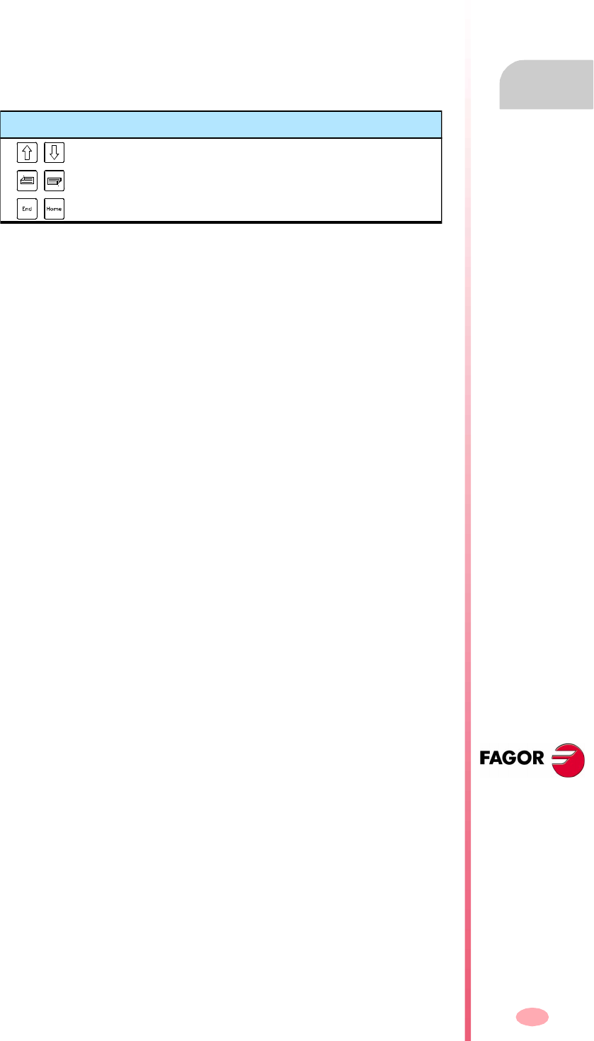
Operating manual
CNC 8070
AUTOMATIC MODE
Data screen (softkeys)
3.
(SOFT V03.0X)
41
3.3 Data screen (softkeys)
3.3.1 First block
It sets the block currently selected with the cursor as the first block to begin execution.
When not setting the starting block, the program will begin executing from the first
block.
The last block may be selected using the cursor or the "Find text" or "Go to line" options
of the softkey menu.
The first block being set remains active until it is canceled (using the [ESC] key) or
until the program is executed; in that case the first block of the program will be
assumed as the first block.
Keys to move the cursor
Moves the cursor line by line.
To move the cursor page by page.
Moves the cursor to the first block or to the end of the program.
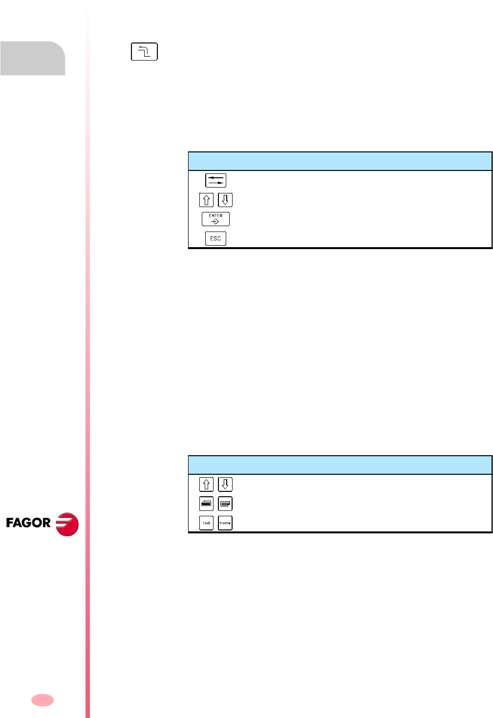
Operating manual
CNC 8070
3.
AUTOMATIC MODE
Data screen (softkeys)
(SOFT V03.0X)
42
3.3.2 Stop condition
To set the block where the execution of the program or subroutine will be interrupted.
After executing that block, the execution may be resumed with the [START] key or
canceled with the [RESET] key.
If the last block is not set, the program execution will end executing one of the end-
of-program functions "M02" or "M30".
Subroutine selection
To select the stop condition in a global subroutine which has been called upon from
the program. When selecting this option, the CNC shows a list of programs available
for selecting the desired subroutine.
To select a subroutine from the list.
1. Select the folder containing the subroutine.
2. Select the program containing the subroutine or write its name in the bottom
window.
3. Press [ENTER] to open the program or [ESC] to cancel the selection and close
the program listing.
The program window will show the contents of the selected subroutine.
Last block
It sets as execution interrupting block the one currently selected with the cursor. If
the last block is not set, the program execution will end executing one of the end-of-
program functions "M02" or "M30".
The last block may be selected using the cursor or the "Find text" or "Go to line" options
of the softkey menu.
The set last block remains active until canceled (with [ESC] key) or until the program
is executed; in that case, the execution will end in one of functions "M02" or "M30".
When selecting this option, the softkey menu of the CNC shows the options available
for selecting the stop condition. To return to the main menu, press the key for the
previous menu.
Keys for selecting a program
To switch windows.
To move the cursor thru the elements of the window.
To open the selected subroutine.
To cancel the selection and close the program listing.
Keys to move the cursor
Moves the cursor line by line.
To move the cursor page by page.
Moves the cursor to the first block or to the end of the program.

Operating manual
CNC 8070
AUTOMATIC MODE
Data screen (softkeys)
3.
(SOFT V03.0X)
43
Number of times
It sets as stop condition, that the block selected as the last block has been executed
a specific number of times.
When selecting this option, the CNC requests the number of times that the block must
be executed before ending the execution of the program. After entering the number
of times, press [ENTER] to validate the value or [ESC] to cancel it.
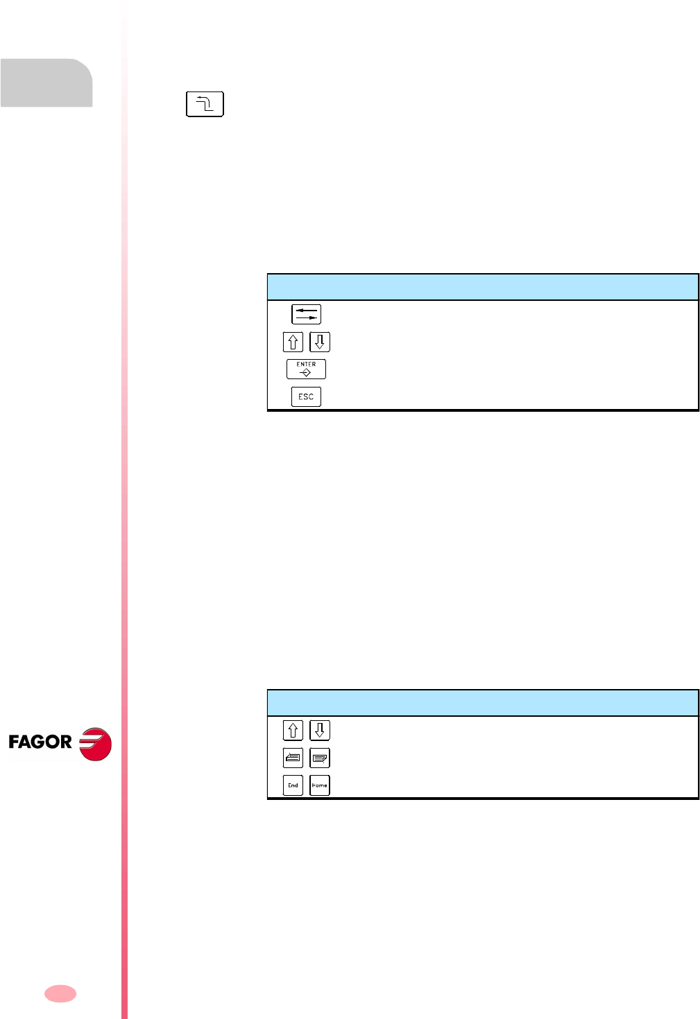
Operating manual
CNC 8070
3.
AUTOMATIC MODE
Data screen (softkeys)
(SOFT V03.0X)
44
3.3.3 Block search
With this option, it is possible, in a program or subroutine, to set the last block in order
to recover the program history and resume program execution from that point on with
the same conditions as if it were executed from the beginning.
When recovering the program history, the CNC reads it up to the indicated block
activating the "G" and "M" functions it reads along the way. Likewise, it sets the
feedrate and speed conditions in the program and calculates the position where the
axes should be.
Subroutine selection
To select the stop condition in a global subroutine which has been called upon from
the program.
When selecting this option, the CNC shows a list of programs available for selecting
the desired subroutine.
To select a subroutine from the list.
1. Select the folder containing the subroutine.
2. Select the program containing the subroutine or write its name in the bottom
window.
3. Press [ENTER] to open the program or [ESC] to cancel the selection and close
the program listing.
The program window will show the contents of the selected subroutine.
Stop block
It sets as the last block for program history recovery the one currently selected with
the cursor. If the program is executed next, it resumes at this block.
The last block may be selected using the cursor or the "Find text" or "Go to line" options
of the softkey menu.
When selecting this option, the softkey menu of the CNC shows the options available
for selecting the stop condition. To return to the main menu, press the key for the
previous menu.
Keys for selecting a program
To switch windows.
To move the cursor thru the elements of the window.
To open the selected subroutine.
To cancel the selection and close the program listing.
Keys to move the cursor
Moves the cursor line by line.
To move the cursor page by page.
Moves the cursor to the first block or to the end of the program.
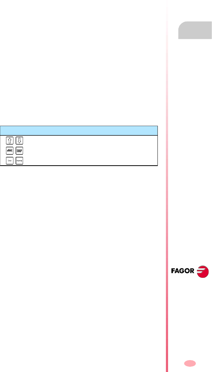
Operating manual
CNC 8070
AUTOMATIC MODE
Data screen (softkeys)
3.
(SOFT V03.0X)
45
Number of times
It sets as stop condition, that the block selected as the stop block has been executed
a specific number of times.
When selecting this option, the CNC requests the number of times that the block must
be executed before ending the history recovery. After entering the number of times,
press [ENTER] to validate the value or [ESC] to cancel it.
If a block containing a multiple machining cycle in ISO code (G160, G161, G162,
G163, G164, G165) or of the cycle editor (L MULTIPLE.CYC) has been selected as
a stop block, the block search will end just before the beginning of the nth modal cycle
repeated in the multiple machining.
Automatic search
With this option, it is possible to recover the program history up to the block where
the execution was interrupted. The CNC remembers the block where it was
interrupted; therefore, the stop block needs not be set.
Starting block
It establishes the block currently selected with the cursor as the first block of the block
search. If the first block is not defined, the block search starts at the first block of the
program.
The last block may be selected using the cursor or the "Find text" or "Go to line" options
of the softkey menu.
Keys to move the cursor
Moves the cursor line by line.
To move the cursor page by page.
Moves the cursor to the first block or to the end of the program.
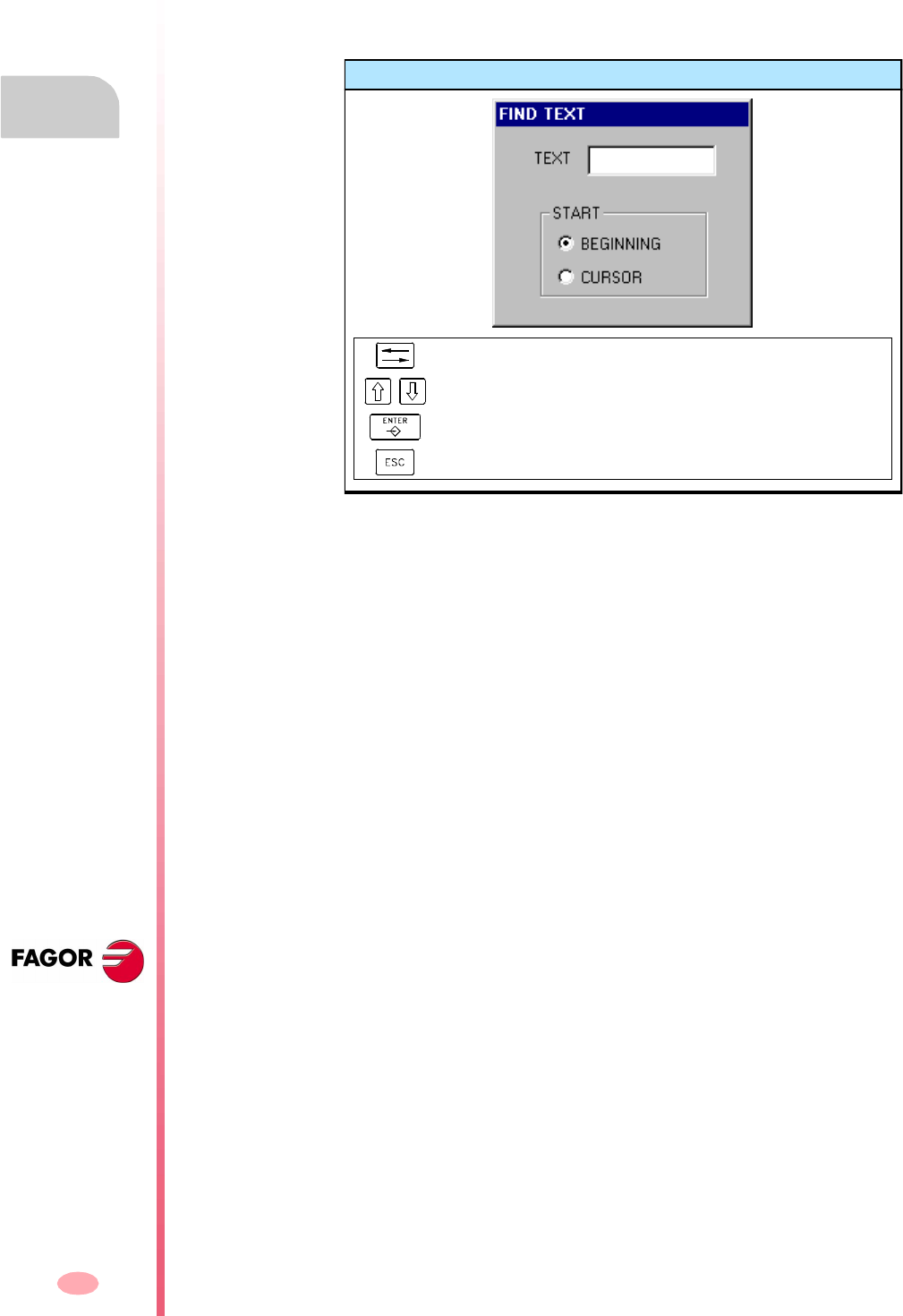
Operating manual
CNC 8070
3.
AUTOMATIC MODE
Data screen (softkeys)
(SOFT V03.0X)
46
3.3.4 Find text
To find text or a character string throughout the program.
When selecting this option, the CNC shows a dialog box requesting the text to be
found. It is also possible to select whether the search must start at the beginning of
the program or at cursor position.
To start the search, press [ENTER] and the cursor will position on the text found. By
pressing [ENTER] again, the CNC will look for the next match and so on.
To end the search, press [ESC]. The cursor will position on the block containing the
text searched.
3.3.5 Go to line
To position the cursor on a particular line of the program.
When selecting this option, the CNC requests the line number. Key in the desired
number and press [ENTER], the cursor will then go to that line.
Find text
To move the cursor through the elements of the list.
It selects an option from a group.
To start the search.
To cancel the search and close the dialog box.
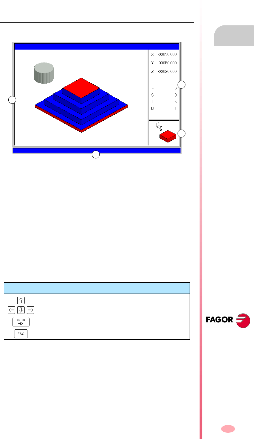
Operating manual
CNC 8070
AUTOMATIC MODE
Graphic screen
3.
(SOFT V03.0X)
47
3.4 Graphic screen
To display a graphic representation of the program that is running and take
measurements on the graphics.
Description of the graphics window
The graphic window shows the following information:
A. Display area.
Shows a graphic representation of the tool paths or of the part as the program
is being executed.
B. Dialog area.
Shows the position of the axes and the machining conditions active in the
execution (feedrate, spindle speed, tool and tool offset).
When selecting specific options of the softkey menu, it shows the information
associated with that option which may be defined by the user.
C. Information area.
Shows the work plane appearing in the display area and an illustration
representing the size of the graph and the portion of the graphic area selected
with the zoom.
On 3D graphics, the illustration shows the point of view of the graph displayed and
it may be changed by the operator.
D. CNC messages.
A
B
C
D
Keys for selecting the point of view
Select a new point of view.
Assumes the new point of view selected.
Cancels the selected point point of view.

Operating manual
CNC 8070
3.
AUTOMATIC MODE
Graphic screen
(SOFT V03.0X)
48
Softkey menus of the graphics window
When selecting the graphic window, the horizontal softkey menu shows the options
associated with that window. The set of options offered by this menu may be changed
using the "+" softkey which offers a new set of options.
The options available in the softkey menu are the following. See "3.5 Graphic
screen (softkeys)" on page 49.
"Type of graphics"
To select the type of graphics.
"ZOOM"
To enlarge or reduce the whole graph shown or part of it.
"Dimensions"
To define the size of the graphic representation.
"Point of view"
To change the point of view of the graph and show it from another perspective.
"Measurement"
To measure the distance between two points.
"Clear screen"
It is used to clear the screen or delete the graphics displayed.
"Colors"
To set the appearance of the graphics on display.
"Options"
To set the appearance and some options of the graphic window.
"+Real"
To display either the real or the theoretical tool path.

Operating manual
CNC 8070
AUTOMATIC MODE
Graphic screen (softkeys)
3.
(SOFT V03.0X)
49
3.5 Graphic screen (softkeys)
3.5.1 Type of graphics
To select the type of graphics.
The various types of graphics may be line (3D lines, XY, XZ, YZ and Combined) or
solid (Sections and 3D solid). Line graphics show the tool path with lines of different
colors and solid graphics show an image of the part being executed.
The type of graphics selected will remain active until another type is selected or the
graphic display is deactivated or the CNC is turned off. Likewise, when changing the
type of graphics, the CNC will maintain the graphic conditions (zoom, graphic
parameters, display area, etc.), defined for the last graphic.
"3D lines" Graphics
It displays a three-dimensional graph of the tool paths.
"Sections" Graphics
It displays a top view (XY plane) of the part being executed and it shows the machining
depths in different tones. It also displays the XZ and YZ sections for the areas shown
by the indicators of the top view.
These indicators may be moved around using the [©][ª][§][¨] keys, to display the
different sections of the part. The CNC shows dynamically the new section being
selected.
The indicators may be moved at any time even while executing the program.
"XY" - "XZ" - "YZ" graphics
It displays the tool paths in the XY, XZ or YZ plane.
"Combined" graphics
It divides the display area in four quadrants and displays the tool path corresponding
to each plane XY, XZ, YZ and to the 3D view.
"Solid 3D" Graphics
It shows a 3D view of the part being machined. Starting out with a 3D block which
is "machined" as the program is executed.
When selecting this option, the softkey menu shows the types of graphics available.
To return to the main menu, press the key for the previous menu.
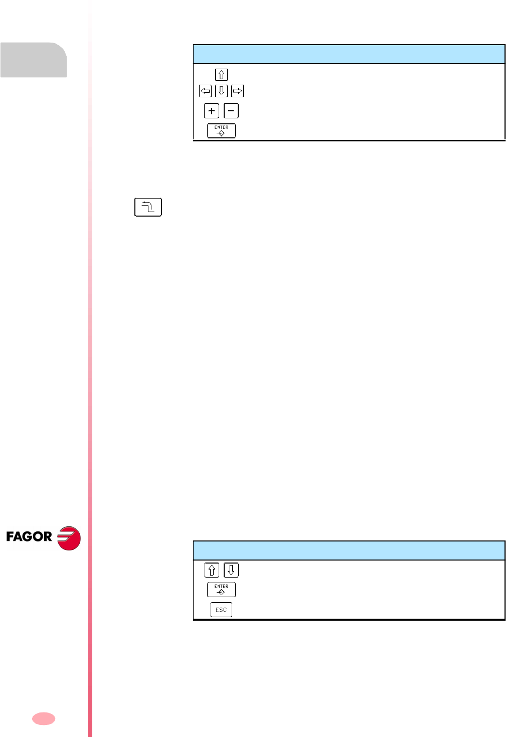
Operating manual
CNC 8070
3.
AUTOMATIC MODE
Graphic screen (softkeys)
(SOFT V03.0X)
50
3.5.2 Zoom
To enlarge or reduce the whole graph shown or part of it. This option is not available
in the "Combined" type of graphics.
After selecting the zoom option, a zoom frame will appear over the graphics. This
frame may be enlarged, reduced and moved around over the graphics already
displayed in order to select a particular portion of it to zoom into or out of.
The graphics at the lower right-hand side of the screen shows two figures. The one
shown with lines only, indicates the dimensions of the display area and the one with
colored sides indicates the portion selected with the zoom.
Zoom "Initial"
Restores the size of the display are set via program or using the "Dimensions" option.
Zoom "Automatic"
The CNC uses the zoom that it considers best according to the movements
programmed.
Zoom "Previous"
It displays up to two zooms defined earlier. After the second one, it shows again the
one defined last.
Zoom "Limits"
Only for the "Sections" type. In this graphics, zooming is done by moving the indicators
that appear framing the graphic sections.
With this option, it is possible to select the axis whose indicator is to be moved.
The indicator may also be selected with the "+" and "-" keys of the numeric keyboard
in a rotary fashion (Xmin, Xmax, Ymin, Ymax, Zmin, Zmax).
Zoom "Edit"
It is used to manually edit the zoom values. It is edited in the dialog area of the graphic
window that shows the dimensions of the zoom frame
Keys for selecting the zoom
To move the zoom frame around.
To change the size of the zoom frame.
To validate and display the selected zoom area.
When selecting this option, the softkey menu shows the available zoom options. To
return to the main menu, press the key for the previous menu.
Keys for defining the zoom
To move the cursor through the data.
To validate and display the defined zoom area.
To cancel the defined zoom.
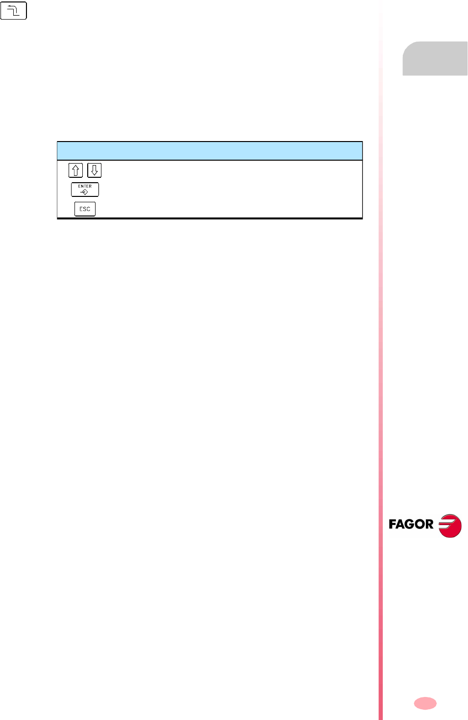
Operating manual
CNC 8070
AUTOMATIC MODE
Graphic screen (softkeys)
3.
(SOFT V03.0X)
51
3.5.3 Dimensions
It is used to define the size of the graphic representation by setting the maximum and
minimum coordinates of the graphics on each axis.
Dimensions "Automatic"
The CNC sets the dimensions that it considers best according to the movements
programmed.
Dimensions "Edit"
It is used to manually edit the dimension values. It is edited in the graphic window
that shows the dimensions of the graphics on each axis.
When selecting this option, the softkey menu shows the options available for setting
the dimensions. To return to the main menu, press the key for the previous menu.
Keys for setting the dimensions
To move the cursor through the data.
To validate and display the set dimensions.
To cancel the set dimensions.
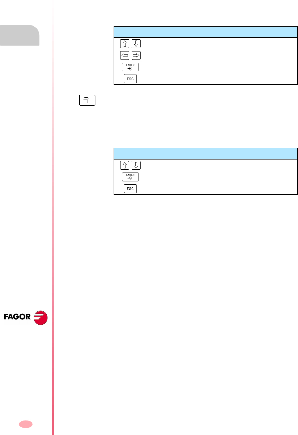
Operating manual
CNC 8070
3.
AUTOMATIC MODE
Graphic screen (softkeys)
(SOFT V03.0X)
52
3.5.4 Point of view
It is used to select the point of view on 3D graphics.
The orientation of the graphics may be directly selected at the graphic window by
orienting the XY plane and the Z axis. The XY plane may be rotated 360º and the
Z axis 90º. The figure at the lower right-hand side of the screen shows the point of
view currently selected.
Point of view "Edit"
It is used to manually edit the orientation of the axes of the graphics. It is edited in
the dialog area of the graphic window that shows the current orientation of the axes.
Keys for selecting the point of view
To orient the XY plane.
To orient the Z axis.
To validate and display the selected point of view.
To cancel the selected point point of view.
When selecting this option, the softkey menu shows the options available for selecting
the point of view. To return to the main menu, press the key for the previous menu.
Keys for defining the point of view
To move the cursor through the data.
To validate and display the defined point of view.
To cancel the defined point of view.
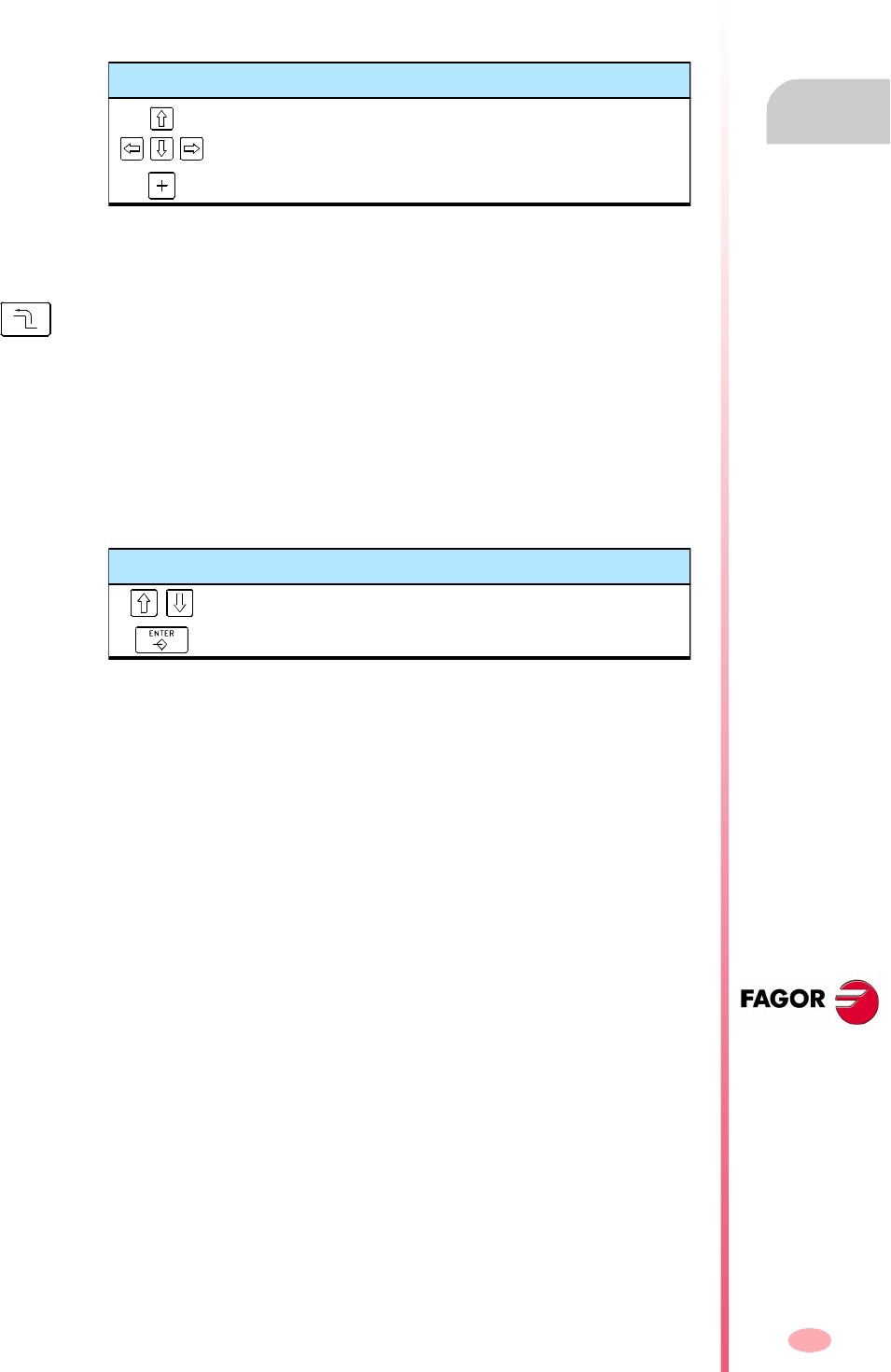
Operating manual
CNC 8070
AUTOMATIC MODE
Graphic screen (softkeys)
3.
(SOFT V03.0X)
53
3.5.5 Measurement
To measure the distance between two points. This option is only available for the types
of graphics "XY", "XZ", "YZ" and "Solid 3D".
When selecting this option, the section being measured will appear on the graphics
with two cursors and a dashed line. The cursor currently selected will appear in red.
The dialog area will show the coordinates of both cursors, the distance between them
on the straight line and the components of that distance on the axes of the active
plane. The coordinates of the selected cursor will appear in red.
Measurement "Point1" & "Point2"
It is used to select the cursor to be moved (same as using the "+" key).
Measurement "Edit"
It is used to manually edit the position of the cursors. It is edited in the dialog area
of the graphic window that shows the position of both cursors.
3.5.6 Clear screen
It is used to clear the screen or delete the graphics displayed.
If a solid graphic type is selected, the graphic representation will be reset and it will
return to its initial state without machining.
Keys to move the cursors
To move the selected cursor.
To select the cursor to be moved.
When selecting this option, the softkey menu shows the available options. To return
to the main menu, press the key for the previous menu.
Keys for defining the measurement
To move the cursor through the data.
To validate the selected position of the cursors.
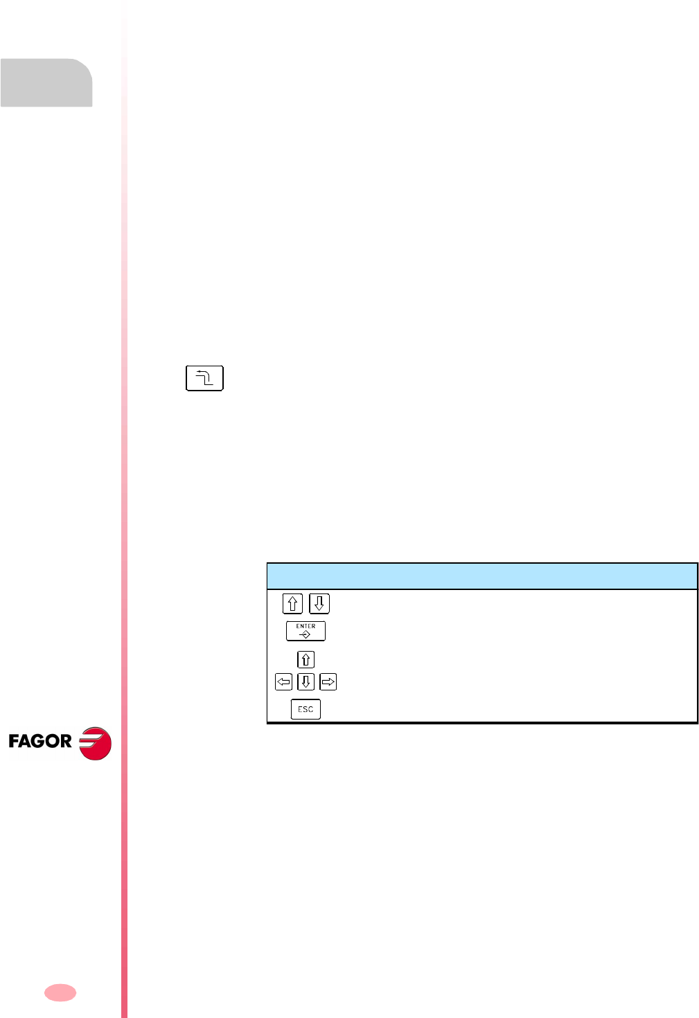
Operating manual
CNC 8070
3.
AUTOMATIC MODE
Graphic screen (softkeys)
(SOFT V03.0X)
54
3.5.7 Colors
It is used to change the colors used in the graphic representation.
Path colors. When a line graphics is active, the following colors may be defined:
The color to draw the rapid traverse.
The color to draw the canned cycles.
The color to draw the compensated path.
The color to draw the theoretical path.
The color to draw the threading.
The color to represent the real coordinates. The real coordinate is the actual
position of the tool which differs from the command coordinate in the amount
of following error (axis lag).
The background color of the window.
Colors for solids. When a solid graphics is active, the following colors may be
defined:
The color to draw the outside X.
The color to draw the inside X.
The color to draw the outside Y.
The color to draw the inside Y.
The color to draw the outside Z.
The color to draw the inside Z.
The background color of the window.
Colors "Apply"
It assumes the new colors and applies them to the blocks drawn next. If the new colors
are not applied, the graphics are drawn with the old colors.
Colors "Edit"
It is used to select the new colors for the graphics. They are selected in the dialog
area of the graphic window that show the current colors.
When selecting this option, the softkey menu shows the available options. To return
to the main menu, press the key for the previous menu.
Keys for defining colors
To move the cursor through the data.
To open and close the color palettes.
To move the cursor through the colors of the palette.
To cancel the selected colors.
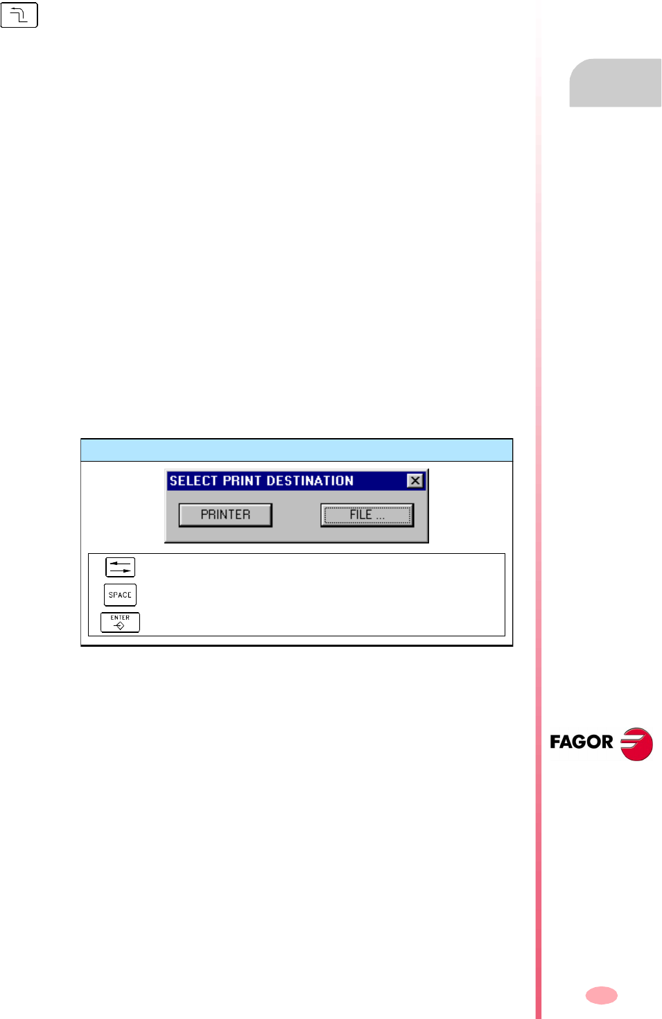
Operating manual
CNC 8070
AUTOMATIC MODE
Graphic screen (softkeys)
3.
(SOFT V03.0X)
55
3.5.8 Options
It is used to set the appearance and some functions of the graphic window. These
options may be used at any time, even while executing a program.
Option "Activate" / "Deactivate"
It is used to activate or deactivate the graphic representation.
When the graphic representation is deactivated and activated, the current graphic is
erased; but the display conditions are kept active (type of graphics, zoom, graphic
parameters and display area) that were active before that mode was deactivated.
Option "Simple" / "Combined"
It is used to hide or show the dialog and data areas on the right-hand side of the
graphic window so the drawing occupies the whole graphic window.
Option "Hide Tool" / "Show Tool"
It is used to hide or show the tool while executing in "3D solid" graphics.
Option "Print"
It is used to print the graphics in a printer connected to the CNC or as a file (BMP
format) at the CNC. When printing to a file, it is saved in the folder:
"C:\Cnc8070\Users\Reports\*.bmp"
When selecting this option, the CNC will show a dialog box requesting the print
destination (printer or file).
After selecting the destination, press [ENTER] to print it or [ESC] to cancel it.
When selecting this option, the softkey menu shows the available options. To return
to the main menu, press the key for the previous menu.
Print destination
To select the print destination.
To print the drawing.
To cancel the printing.
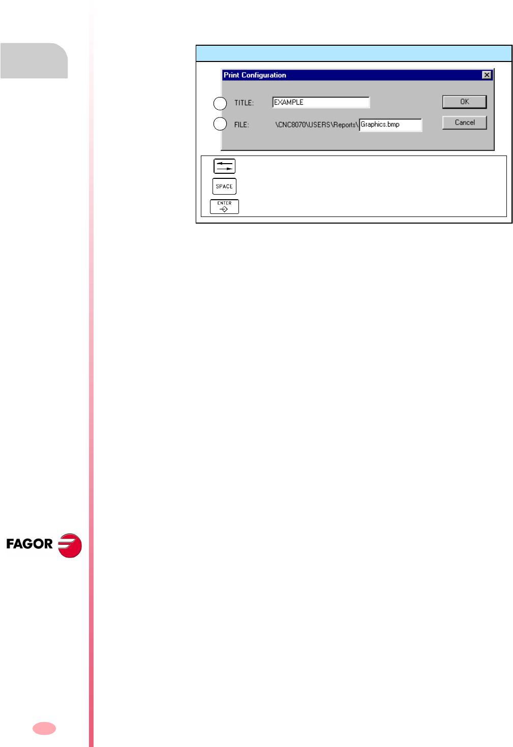
Operating manual
CNC 8070
3.
AUTOMATIC MODE
Graphic screen (softkeys)
(SOFT V03.0X)
56
Option "Print setup"
It is used to set the printing configuration.
When selecting this option, the CNC shows a dialog box where the following may be
defined:
A. The title of the graphics that will appear next to it in the print.
B. The name of the file where the graphics will be stored when printing out to a file.
After filling out the data, press [ENTER] to accept them or [ESC] to cancel them.
3.5.9 Real coordinates
It is used to draw the real tool path or the theoretical tool path. This option is only
available in line type graphics.
When selecting this option (the softkey will appear pressed), the CNC draws the
actual (real) tool path.
Print configuration
To move the cursor through the elements of the list.
To accept the configuration defined.
To cancel the defined configuration.
A
B

Operating manual
CNC 8070
AUTOMATIC MODE
Program selection and execution
3.
(SOFT V03.0X)
57
3.6 Program selection and execution
3.6.1 Program selection
A different program may be selected and executed in each channel. The program is
executed in the channel where it is selected from.
Once a program has been selected, its name appears on the general status bar. For
each channel, it shows the name of the program selected in that channel.
To select a program, press the icon "Select program" of the softkey menu and the CNC
will show a list of all the programs available. See "2.5 File selection window" on
page 22.
Operating manual
CNC 8070
3.
AUTOMATIC MODE
Program selection and execution
(SOFT V03.0X)
58
3.6.2 Program execution
The name of the program selected in the channel for execution appears on the
general status bar. See "3.1.2 Description of the general status bar" on page 36.
If not indicated otherwise, the program execution will begin from the first block of the
program to the execution of one of the end-of-program functions "M02" or "M30". As
an option, it is possible to define the first and last blocks of the execution. See
"3.3 Data screen (softkeys)" on page 41.
Start executing
To start the execution of the program, press [START] on the Operator Panel.
The program may be executed in –single block– or –automatic– mode; the mode may
be selected even while executing the program. When –single block– is active, the
screen will display the relevant symbol on the general status bar.
If the –single block– mode is active, program execution will be interrupted at the end
of each block; the [START] key must be pressed again to execute the next block. If
the –automatic– mode is active, the program will be executed all the way to the end
or up to the block selected as end of execution.
Interrupting the execution
The [STOP] key interrupts the execution of the program. Press [START] again to
resume execution from where it was interrupted.
The execution may be interrupted at any time, except when threading. In that case,
it will be interrupted at the end of the threading operation.
Stop the execution
The [RESET] key cancels the execution of the program and resets the CNC to its initial
conditions.
The program selected for execution may be executed in any operating mode
by pressing [START] on the Operator Panel. The CNC will request
confirmation before starting to execute the program.
i
Operating manual
CNC 8070
AUTOMATIC MODE
Program selection and execution
3.
(SOFT V03.0X)
59
3.6.3 Tool inspection
Once tool inspection is completed and before resuming the execution of the program,
the spindle must be started and the axes repositioned to the point where tool
inspection began. Once the axes are repositioned, press [START] to resume program
execution.
Rigid tapping and tool inspection mode
When interrupting the rigid tapping and accessing the tool inspection mode, it is
possible to jog the axes (only in jog mode) that are involved in threading. When moving
the axis, the interpolated spindle will also move; the spindle used to make the thread.
If rigid tapping involves several axes, when moving one of them, all the other ones
involved in the thread will also move.
This allows moving the axis into or out of the thread as often as desired until pressing
the repositioning softkey. The axes move at the programmed F except when an axis
or spindle exceeds its maximum feedrate allowed (parameter MAXMANFEED), in
which case, the feedrate will be limited to that value.
The spindle jogging keys are disabled during tool inspection. It is only possible to get
out of the thread by jogging one of the axes involved in rigid tapping. Functions M3,
M4, M5 and M9 cannot be programmed at the spindle; they are ignored.
While repositioning, when selecting one of the axes of the thread on the softkey menu,
it will move all the axes and spindle involved in the thread.
Reposition the axes and the spindle
The axes and the spindle may be repositioned simultaneously.
Reposition the axes.
The axes may be repositioned one by one or all at the same time. To reposition them,
select the axes with the relevant softkey and press [START]. The axes reposition at
the feedrate defined by the OEM.
The axes may be repositioned using the JOG keys or handwheels. On the other hand,
repositioning may be interrupted (using the [STOP] key) to select other axes. Once
one axis has reached its position, it will no longer be available.
This option is only available when the running program has been interrupted.
Activating tool inspection makes the following operations possible:
•Jogging the axes using the JOG keys of the operator panel or handwheels.
•Stop and start the spindle using the keys on the operator panel.
•Access the CNC tables (tools, tool offsets, etc.) and modify their data.
To end tool inspection and reposition the spindle and the axes at the point where tool
inspection began, press the relevant icon.
After pressing this icon, the CNC will show a list of the axes that are out of position.
If the spindle was stopped during tool inspection, next to the list of axes, it will also
show the status that the spindle had before the inspection.

Operating manual
CNC 8070
3.
AUTOMATIC MODE
Program selection and execution
(SOFT V03.0X)
60
Restore the spindle turning direction.
The spindle turning direction may be restored together with the axes or separately.
To do this, it shows, next to the axes to be repositioned, the previous status of the
spindle (M3, M4 or M19). To restore the turning direction, select the softkey and press
[START].
Operating manual
CNC 8070
AUTOMATIC MODE
Program selection and execution
3.
(SOFT V03.0X)
61
3.6.4 Block search and program execution
With block search, it is possible to recover the program history up to a particular block
in such way that if program execution is resumed at that block, it will do so with the
same conditions as if it were executed from the beginning.
There are two types of block search:
•Automatic
To recover the program history up to the block where the execution was canceled.
The CNC remembers the block where interruption was canceled, thus not being
necessary to set the stop block.
•Manual
To recover the program history up to a particular block set by the operator.
When recovering the program history, the CNC reads it up to the indicated block
activating the "G" and "M" functions it reads along the way. Likewise, it sets the
feedrate and spindle speed conditions of the program and calculates the position
where the axes should be.
To recover the program history, proceed as follows:
1. To do an automatic search, i.e. restore the history up to the point where the
program was interrupted, press "Automatic Search". The search starting point
may be chosen by selecting the first block.
2. For a manual search, set the last point using the stop block, select the subroutine
(optional) and the number of times (optional). The search starting point may be
chosen by selecting the first block.
3. Press [START] to recover the program history.
The CNC will set the feedrate and speed conditions of the program and will start
the spindle in the set direction ("M3" or "M4"). It will also activate the "M" and "G"
functions defined in the program.
4. Reposition the axes to the position to resume execution.
5. Press [START] to execute the program.
Reposition the axes.
•Manually
Jog the axes with the handwheels or with the JOG keys. The movement is limited
by the repositioning end point and the corresponding software limit.
•Automatically
Select the axes with the relevant softkey and press [START]. Repositioning may
be interrupted (using the [STOP] key) to select other axes.
When an axis reaches the repositioning end point, it is no longer available; however,
this axis may be moved with the handwheel or the JOG keys under the same
conditions as before. Once all the axes have been repositioned, none of them may
be moved.
To reposition the axes, press the corresponding icon and the CNC will show the axes
that are out of position.
The axes may be repositioned individually or several at the same time in one of the
following ways:

Operating manual
CNC 8070
3.
AUTOMATIC MODE
Program selection and execution
(SOFT V03.0X)
62

63
CNC 8070
(SOFT V03.0X)
4
MANUAL (JOG) MODE
Jog (manual) mode selection
In the same channel, the jog mode cannot be accessed while a program is running
or a block is being executed in MDI. The jog mode may be accessed in the rest of
the channels.
If the execution of the program has been interrupted, the CNC will cancel the
execution of the program and will go into jog mode. A program is interrupted when
the [STOP] has been pressed or is waiting in single-block mode.
When accessing the jog mode from the automatic mode, the CNC keeps the
machining conditions selected in the last mode.
Operations in this work mode
The following operations are possible in this work mode:
•Display various data related to axes position.
(Position referred to part zero or to home, following error, etc.).
•Home the axes (Machine reference zero search).
•Jog the axes using the keys on the operator panel or electronic handwheels.
•Move an axis to a position by previously selecting the target point.
•Preset a coordinate.
•Start and stop the spindle manually using the keys of the operator panel.
•Change tools.
•Activate up to 16 external devices using the keys of the upper side of the operator
panel. The external devices associated with each key must be defined by the
machine manufacturer.
•Calibrate a tool in jog mode (without probe), in semi-automatic mode (when using
a table-top probe) or using the tool calibration cycle (also when using a table-top
probe).
The manual (JOG) mode may be accessed from any other operating mode, except
when a program is in execution, by pressing its relevant key.

Operating manual
CNC 8070
4.
MANUAL (JOG) MODE
Appearance of the Manual (JOG) mode
(SOFT V03.0X)
64
4.1 Appearance of the Manual (JOG) mode
This mode may be displayed with several screens. The current screen and the total
number of available screens are shown at the upper right hand side of the general
status bar.
Switching between the different screens is done by pressing the jog mode accessing
key. The screen selection is rotary in such a way that when pressing this key on the
last screen, it shows the first one of the operating mode.
Standard configuration
The standard configuration of this work mode, described in this manual corresponds
to the one supplied by Fagor. In some cases, the manual shows a sample screen,
instead of that of the CNC in order to make it easier to understand.
These screens may be customized by the machine manufacturer changing its
contents as well as its appearance. They may also remove certain screens or add
some of their own.
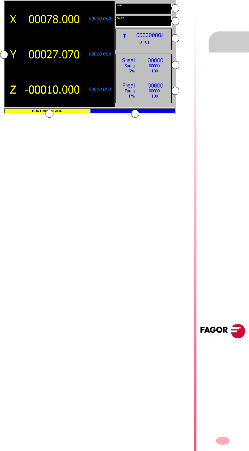
Operating manual
CNC 8070
MANUAL (JOG) MODE
Appearance of the Manual (JOG) mode
4.
(SOFT V03.0X)
65
4.1.1 Description of a typical screen of this work mode
A typical screen of the jog mode can show the following information:
A. Information related to the position of the axes. In the screen configuration supplied
by Fagor, the data displayed will be different on each screen.
The most common thing is to show the current position of the axes referred to part
zero in large characters, and the amount of following error (axis lag) in small
characters.
Another more detailed option shows the coordinates of the tool tip and those of
the tool base, being both referred to part zero and machine zero.
B. Active "M" functions.
C. Active "G" functions and high-level commands.
D. Tool related information.
Tool number "T" currently selected and active tool offset "D" associated with the
tool.
E. Information related to the spindle speed "S".
"Sreal" Actual spindle speed.
"Sprog" Programmed speed.
"S%" Percentage of speed override being applied on to the programmed
value.
Depending on the active screen, it will also show the spindle position "SPOS" and
its following error "SFWE".
F. Information related to the feedrate "F" of the axes:
"Freal" Actual feedrate of the axes.
"Fprog" Programmed feedrate.
"F%" Percentage of feedrate override being applied on to the
programmed value.
G. Moving mode selected at the jog selector switch on the operator panel.
H. Reserved.
A
B
C
D
E
F
G H

Operating manual
CNC 8070
4.
MANUAL (JOG) MODE
Appearance of the Manual (JOG) mode
(SOFT V03.0X)
66
4.1.2 Vertical softkey menu (icons)
Display units (millimeters/inches).
It is used to change the units for displaying the position (coordinates) of the linear axes
and the feedrate data. Toggling these units does not affect the rotary axes which will
always be displayed in degrees.
The icon highlights the units currently selected (millimeters or inches).
It must be borne in mind that the units can only be changed on the data display. A
program assumes the units defined with the active function "G70" or "G71", or, when
not programmed, the units set by the machine manufacturer.
Load zero offset or fixture offset tables.
It may be used to save the active zero offset in the zero offset or fixture offset table.
Tool calibration.
It accesses the tool calibration screens.
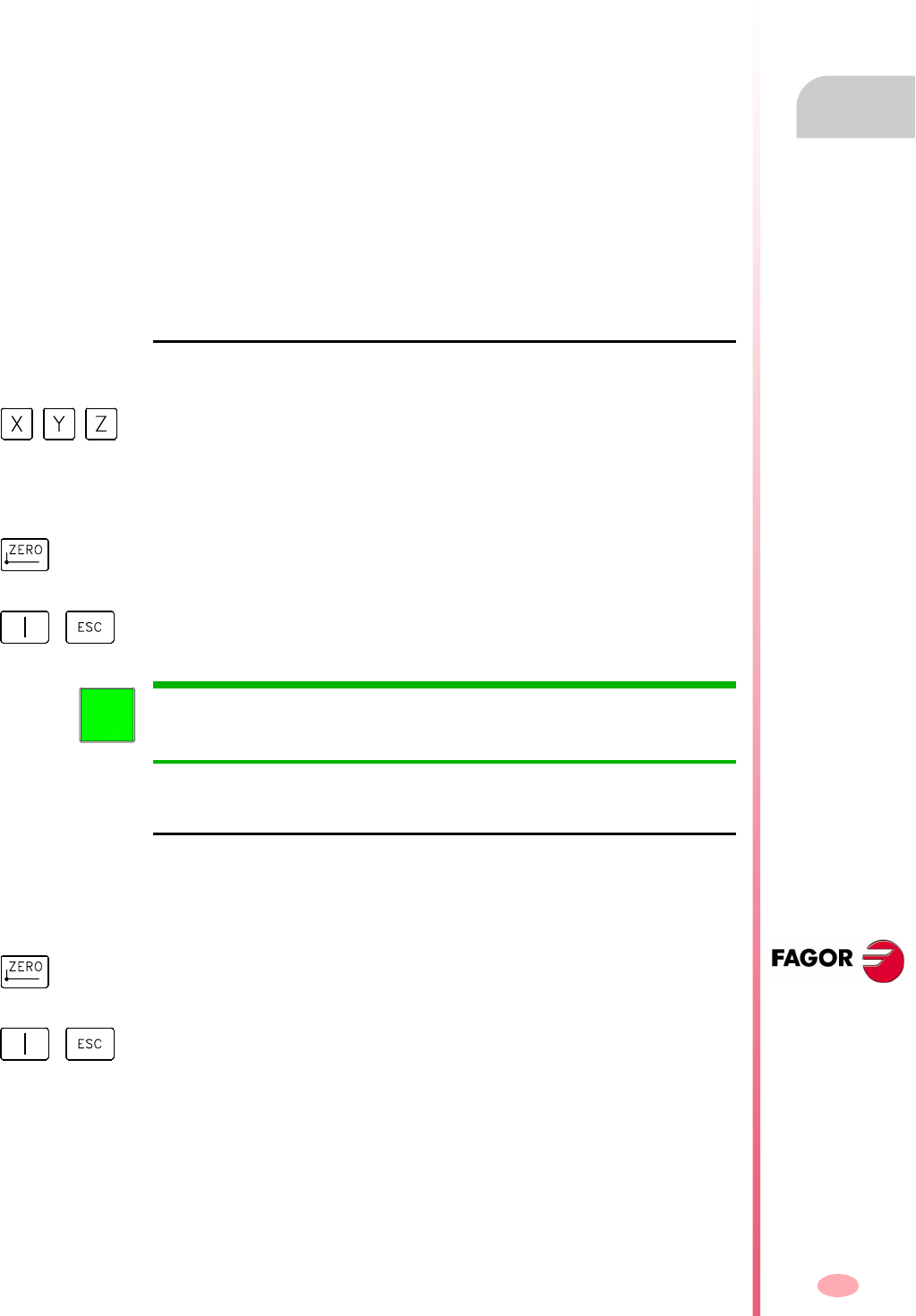
Operating manual
CNC 8070
MANUAL (JOG) MODE
Operations with the axes
4.
(SOFT V03.0X)
67
4.2 Operations with the axes
4.2.1 Home search
It is the operation used to synchronize the system. This operation must be carried
out when the CNC loses the position of the origin point (e.g. by turning the machine
off).
When "searching home", the axes move to the machine reference point and the CNC
assumes the coordinate values assigned to that point by the machine manufacturer,
referred to machine zero. When using distance-coded reference marks or absolute
feedback, the axes will only move the distance necessary to verify their position.
The axes may be homed manually or automatically.
•Manual homing is done one axis at a time, from the operator panel.
•Automatic homing is done with a subroutine defined by the machine
manufacturer.
Manual home search
It is done one axis at a time. Home search of an axis is carried out as follows:
Automatic home search
This homing method is only available if the machine manufacturer has previously
defined a homing subroutine.
Home search using a subroutine is carried out as follows:
1. Select the axis to be homed using the alphanumeric keyboard. The CNC will
highlight that axis to indicate that it is selected.
To select the numbered axes (e.g. "X1"), select any axis and then move the
selection until positioning on the desired one. The focus moves with the [©][ª]
keys.
2. Press the homing key [ZERO]. The CNC will display the "1" symbol in the numeric
area indicating that a home search will take place.
3. Press [START] to go ahead with the home search or [ESC] to cancel the operation.
When searching home in this mode, the CNC cancels the zero offset, the
fixture offset and the measuring offset. It assumes the machine reference zero
point (home) as the new part zero.
i
1. Press the homing key [ZERO]. The CNC will display a dialog box requesting
confirmation to execute the home search.
2. Press [START] to go ahead with the home search or [ESC] to cancel the operation.
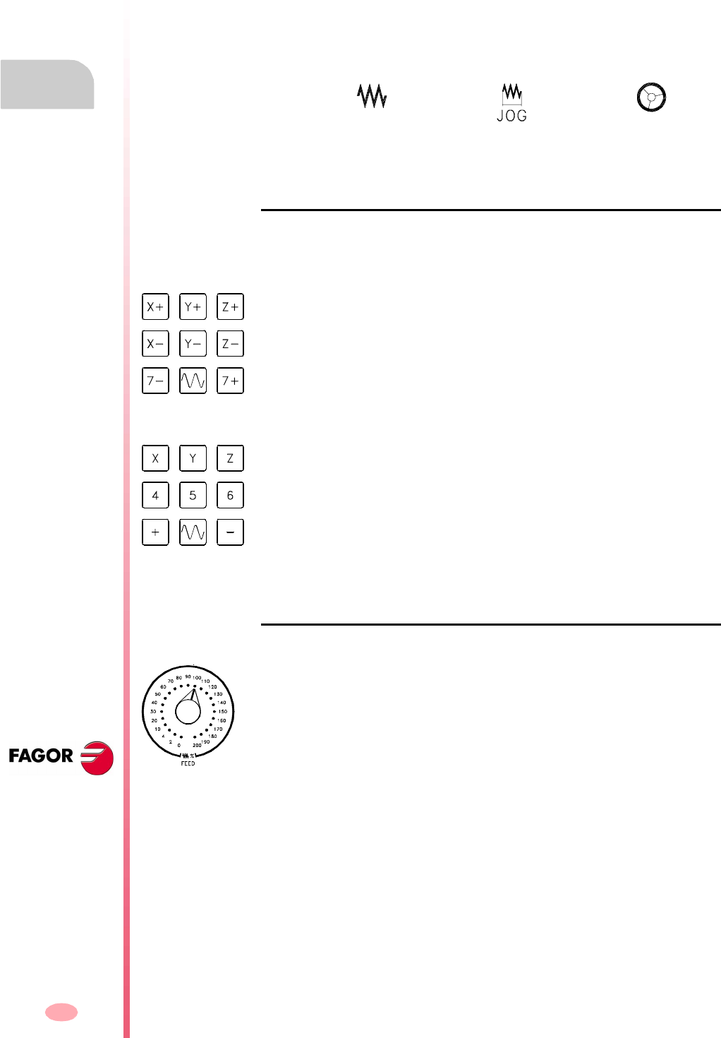
Operating manual
CNC 8070
4.
MANUAL (JOG) MODE
Operations with the axes
(SOFT V03.0X)
68
4.2.2 Jogging the axes
The axes may be jog using the JOG keyboard on the operator panel. Two types of
movements may be made.
•Continuous jog, when the axis moves while acting on the keyboard.
•Incremental jog, when the axis moves a specific distance every time the operator
acts on the keyboard.
The type of jog is selected with the jog selector switch on the operator panel.
JOG keys
There are two types of jog keyboards depending on the behavior of the keys.
Type I
Type II
Feedrates
Continuous jog Incremental jog Handwheels
There are two keys for each axis. One to jog the axis in the positive direction and
another one to move it in the negative direction.
To move a single axis, press the axis key and the one for its jogging direction.
There is a key for each axis and two keys for moving direction, common to all the axes.
To jog an axis requires activating both the axis key and the moving direction. There
are two options, depending on how the jog keyboard has been configured.
•The axis will move while both keys are pressed, the axis key and the direction key.
•When pressing the axis key, the key remains active. The axis will move while the
direction key is kept pressed. To de-select the axis, press [ESC] or [STOP].
The movement is carried out at the feedrate defined by the OEM. The feedrate may
be varied between 0% and 200% using the feedrate override switch on the operator
panel.
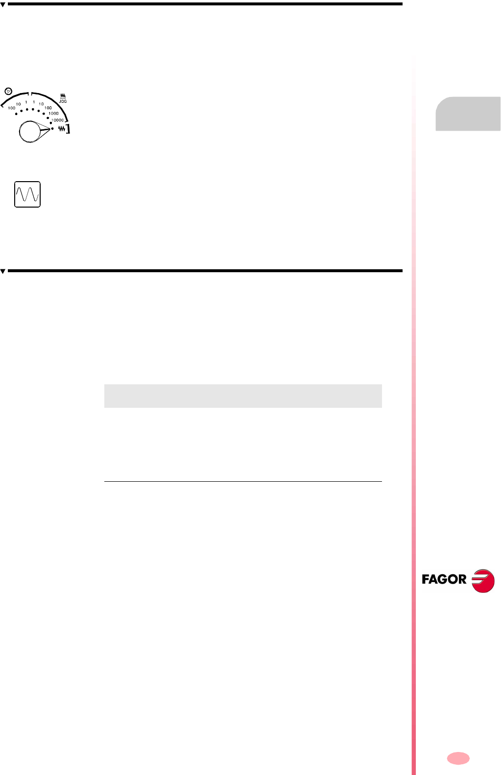
Operating manual
CNC 8070
MANUAL (JOG) MODE
Operations with the axes
4.
(SOFT V03.0X)
69
Continuous JOG
In continuous jog, the axes keep moving while the jog keyboard is acted upon.
Continuous jog allows moving several axes at the same time.
Proceed as follows:
Incremental JOG
In incremental jog, the axis moves a specific distance every time the key is pressed.
In incremental jog, the axes may be jogged simultaneously.
Proceed as follows:
1. Turn the jog selector switch of the operator panel to one of the incremental jog
positions. Each position will move the axis a fixed distance; the typical values are
the following.
2. Jog the desired axis using the JOG panel (keypad). Every time the JOG panel
is acted upon, the axis will move the distance indicated on the dial of the jog
selector switch.
If while moving, a second axis is selected, the new one will move at the same time
and under the same conditions.
1. Turn the jog selector switch
(a)
of the operator panel to the continuous jog position
on the dial.
2. Jog the desired axis using the JOG panel (keypad). The axis will move while acting
upon the JOG panel.
If while moving, a second axis is selected, the new one will move at the same time
and under the same conditions.
(a)
If while the axes are moving, the rapid key is pressed, the axes will move at the rapid
rate set by the machine manufacturer. This feedrate will be applied while that key is
kept pressed and, when released, the axes will recover their previous feedrate. This
rapid rate may be varied between 0% and 200% with the feedrate override switch on
the operator panel.
Selector position Distance
1 0.001 mm or 0.0001 inches
10 0.010 mm or 0.0010 inches.
100 0.100 mm or 0.0100 inches.
1000 1.000 mm or 0.1000 inches.
10000 10.000 mm or 1.0000 inches.

Operating manual
CNC 8070
4.
MANUAL (JOG) MODE
Operations with the axes
(SOFT V03.0X)
70
4.2.3 Jogging the axes with handwheels
Up to three electronic handwheels may be used to move the axes.
Depending on configuration, there may be a general handwheel to move any axis or
an individual handwheel per axis that will only move its associated axis.
Once the desired resolution has been selected and depending on the type of
handwheel being used, general or individual, proceed as follows.
General handwheel
The general handwheel is not associated with any axis in particular. It may be used
to move any axis of the machine (if the manufacturer has set it that way).
Proceed as follows.
1. Select the axis to be jogged.
On the JOG keyboard, press one of the keys for the axis to be jogged. If several
axes are selected simultaneously, they all move at the same time.
The CNC will highlight them, indicating that they are selected. When selecting an
axis or quitting the handwheel mode using the movement selector, the previous
one is automatically deselected.
2. Once the axis has been selected, the CNC will move it as the handwheel is turned
depending on the setting of the selector switch and on the turning direction of the
handwheel.
The feedrate depends on how fast the handwheel is turned.
To move the axes with the handwheels, turn the jog selector switch
(a)
of the operator
panel to one of the handwheel positions. Every position indicates the multiplying
factor applied to the handwheel pulses; the typical values are the following.
(a)
Selector position Distance
1 0.100 mm or 0.0100 inches.
10 1.000 mm or 0.1000 inches.
100 10.000 mm or 1.0000 inches.

Operating manual
CNC 8070
MANUAL (JOG) MODE
Operations with the axes
4.
(SOFT V03.0X)
71
Individual handwheel
The individual handwheel is associated with a particular axis. The CNC moves each
axis as its relevant handwheel is turned depending on the setting of the selector
switch and on the turning direction of the handwheel.
When moving several axes simultaneously using handwheels, all the axes having
their own handwheel plus another one selected with the general handwheel may be
involved.
When moving several axes at the same time, the feedrate of each axis depends on
how fast its associated handwheel is turned.
It may happen that depending on the turning speed and the selector position,
the CNC be demanded a faster feedrate than the maximum allowed. In that
case, the CNC will move the axis the indicated distance but at the maximum
feedrate allowed.
i
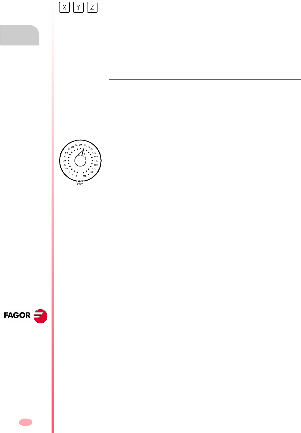
Operating manual
CNC 8070
4.
MANUAL (JOG) MODE
Operations with the axes
(SOFT V03.0X)
72
4.2.4 Moving an axis to a particular position (coordinate)
When moving the axes to a specific position, they must do so one by one following
these steps:
2. Enter the coordinate of the target point.
3. Press [START] to execute the movement or [ESC] to cancel the operation.
Feedrate behavior
The moving feedrate depends on whether G00 or G01 is active.
•If G00 is active, the movement is carried out at the rapid rate defined by the
machine manufacturer.
•If G01 is active, the movement is carried out at the active feedrate. If no feedrate
is active, the movement is executed at the feedrate defined by the machine
manufacturer.
1. Select the axis to be homed using the alphanumeric keyboard. The CNC will
highlight that axis to indicate that it is selected.
To select the numbered axes (e.g. "X1"), select any axis and then move the
selection until positioning on the desired one. The focus moves with the [©][ª]
keys.
This feedrate may be varied between 0% and 200% using the feedrate override
switch
(a)
on the operator panel. The percentage will be applied on to all the
movements carried out in G00 and in G01.
(a)
Operating manual
CNC 8070
MANUAL (JOG) MODE
Operations with the axes
4.
(SOFT V03.0X)
73
4.2.5 Coordinate preset
Coordinates must be preset axis by axis following these steps:
2. Key in the desired preset value.
3. Press [START] to preset the entered value or [ESC] to cancel the operation.
The preset may be canceled by homing the axes one by one or by means of function
"G53".
1. Select the axis to be homed using the alphanumeric keyboard. The CNC will
highlight that axis to indicate that it is selected.
To select the numbered axes (e.g. "X1"), select any axis and then move the
selection until positioning on the desired one. The focus moves with the [©][ª]
keys.
Operating manual
CNC 8070
4.
MANUAL (JOG) MODE
Spindle control
(SOFT V03.0X)
74
4.3 Spindle control
The spindle may be controlled manually using the following keys of the operator
panel. The keys always refer to the master spindle of the active channel.
The spindle speed should be set (in the MDI mode) before selecting the turning
direction, thus avoiding a sudden start of the spindle when setting an "S" because
the turning direction was active.
Starts the spindle clockwise. Same as function M03.
Start the spindle counteclockwise. Same as function M04.
To stop the spindle. Same as function M05.
Spindle speed override.
Spindle orientation. Same as function M19.
Customizing the keys
The machine manufacturer sets the minimum and maximum percentages between
which the speed may be varied as well as the percentage of variation every time one
of these keys is pressed.
They are set using the following machine parameters.
MINOVR Minimum override.
MAXOVR Maximum override.
STEPOVR Override increment (step).
Starts the spindle clockwise at the active speed.
Displays function M03 in the history of the current machining conditions.
Starts the spindle counterclockwise at the active speed.
Displays function M04 in the history of the current machining conditions.
To stop the spindle.
Displays function M05 in the history of the current machining conditions.
It may be used to vary the spindle turning speed, a typical value being a variation
between 50% and 120%. Every time one of these keys is pressed, the speed varies
5%.
These values may be different depending on how the machine manufacturer has
defined them.
It orients the spindle.
Displays function M19 in the history of the current machining conditions.

Operating manual
CNC 8070
MANUAL (JOG) MODE
Tool selection and tool change
4.
(SOFT V03.0X)
75
4.4 Tool selection and tool change
The tool located in the spindle may be changed in manual mode. Proceed as follows.
1. Press [T] at the alphanumeric keyboard. The CNC will highlight the current tool
indicating that it is selected.
2. Key in the number of the tool to be placed in the spindle.
3. Press [START] to execute the tool change or [ESC] to cancel the operation.

Operating manual
CNC 8070
4.
MANUAL (JOG) MODE
Definition of cutting conditions
(SOFT V03.0X)
76
4.5 Definition of cutting conditions
In jog mode, it is possible to set the turning speed "S" and the feedrate "F".
•The feedrate will correspond to the active feedrate.
•The speed entered will correspond to the master spindle of the active channel.
Proceed as follows.
1. Press the [S] key on the alphanumeric keypad to select a spindle speed or the
[F] key to select a feedrate. The CNC will highlight the relevant data indicating that
it is selected.
2. Enter the desired spindle speed or feedrate.
3. Press [START] to assume the entered value or [ESC] to cancel the operation.

Operating manual
CNC 8070
MANUAL (JOG) MODE
Automatic loading of zero offsets or fixture offset tables
4.
(SOFT V03.0X)
77
4.6 Automatic loading of zero offsets or fixture offset tables
Proceed as follows:
1. Press the icon for "Load table". The CNC shows the list of available zero offsets
and fixture offsets.
2. Select the zero offset or fixture offset where you wish to save the active offset.
3. Press [ENTER] to enter the offset in the table.
The [ESC] key cancels the operation at any time.
It may be used to save the active zero offset in the zero offset or fixture offset table.
This operation is carried out using the "Load table" icon.

Operating manual
CNC 8070
4.
MANUAL (JOG) MODE
Automatic loading of zero offsets or fixture offset tables
(SOFT V03.0X)
78
79
CNC 8070
(SOFT V03.0X)
5
MANUAL (JOG) MODE. TOOL
CALIBRATION
Tool calibration is available in the jog mode. The softkey to access tool calibration will
be different depending on the software installed (lathe model or mill model). To quit
the calibration mode and return to jog mode, press the [ESC] key.
The CNC offers in both models the possibility to calibrate lathe tools and milling tools.
The CNC will show the necessary data and will update the help graphics according
to the selected tool.
Types of calibration
There are several ways to calibrate a tool. Some ways are only available when using
a table-top probe.
The active kinematics are taken into account and do not prevent tool calibration in
this mode. Manual or semi-automatic calibration will not be possible if a coordinate
( #CS or #ACS) transformation is active or when either the RTCP or TLC function is
active.
Manual calibration.
It is done without the table-top probe. A reference part is required to calibrate the tool.
All the movements are carried out manually.
Semi-automatic calibration.
Available when using a table-top probe. It cannot be used to calibrate lathe tools. The
positioning movements are carried out manually and the CNC executes the probing
movements.
Automatic calibration.
Available when using a table-top probe. The CNC executes all the movements using
the calibration canned cycle #PROBE.
Icon to access tool calibration in a mill model.
Icon to access tool calibration in a lathe model.
Only manual calibration is possible when not using a table-top probe. All types of
calibration are available when using a table-top probe. The different calibration
methods may be selected from the vertical softkey menu.
Operating manual
CNC 8070
5.
MANUAL (JOG) MODE. TOOL CALIBRATION
(SOFT V03.0X)
80
Probe selection
Two probes may be configured at the CNC. The probe active at the time is used for
calibration. The active probe may be changed via part-program or MDI using the
instruction #SELECT PROBE.
Geometrical configuration of the axes: "plane" or "trihedron".
At the lathe model, the geometrical configuration of the axes may be either of the
"plane" or "trihedron" type depending on the availability of a third main axis, usually
the ·Y· axis. The different calibration modes adapt to the current configuration
showing the necessary data for each one of them.
Configuration of "plane" type axes. The longitudinal axis.
In this configuration, the second axis of the channel is considered as longitudinal axis.
If the X (first) and Z (second) axes have been defined, the work plane will be the ZX
and Z will be the longitudinal axis. Tool length compensation is applied on this
longitudinal axis when using milling tools. With lathe tools, tool length compensation
is applied on all the axes where a tool offset has been defined.
When using milling tools on a lathe, the longitudinal compensation axis may be
changed by means of the #TOOL AX instruction or the G20 function.
#SELECT PROBE [1]
Selects the first probe.
#SELECT PROBE [2]
Selects the second probe.
Geometrical configuration of "trihedron" type
axes.
It is the typical configuration of a milling machine or of
a lathe that has a third main axis (·Y· axis).
There are three axes forming a Cartesian XYZ type
trihedron like on a milling machine. There may be more
axes besides those forming the trihedron.
With this configuration, the planes behave in the same
way as on a milling machine except that the usual work
plane will be G18 (if it has been configured like that).
Geometrical configuration of "plane" type axes.
It is the typical configuration of a lathe.
There are two axes forming the usual work plane. There
may be more axes, but they cannot be part of the
trihedron; there must be auxiliary, rotary, etc.
With this configuration, the active plane will be formed
by the first two axes defined in the channel. If the X (first)
and Z (second) axes have been defined, the work plane
will be the ZX (Z as abscissa and X as ordinate).
The work plane is always G18; the plane cannot be
changed via part-program.
Z
X
Y
Z
X
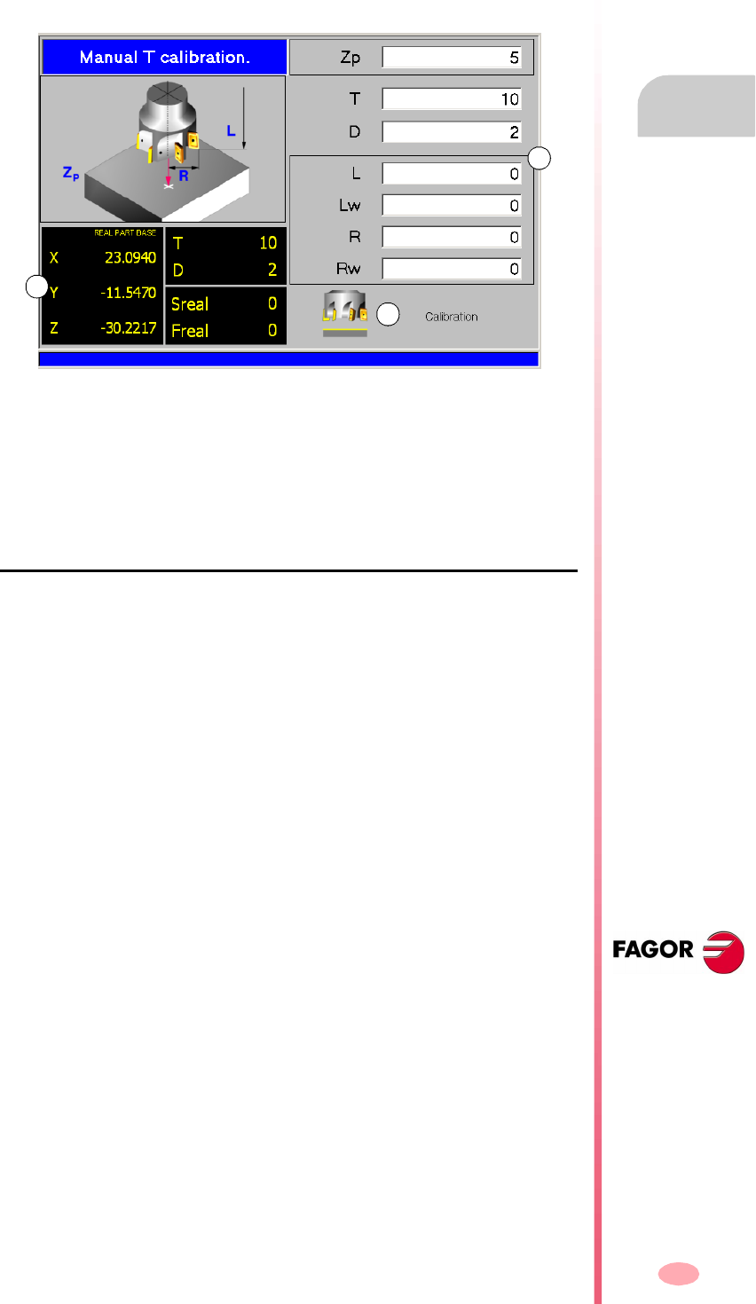
Operating manual
CNC 8070
MANUAL (JOG) MODE. TOOL CALIBRATION
Manual calibration. Calibration without a probe
5.
(SOFT V03.0X)
81
5.1 Manual calibration. Calibration without a probe
In this mode, only the active tool can be calibrated and it may be a milling tool or a
lathe tool. The CNC will show the necessary data and will update the help graphics
according to the selected tool.
A. Machine data. Position of the axes, tool and active tool offset, real spindle speed
and real feedrate of the axes.
B. Area to define the calibration data.
C. Drawing indicating that tool calibration is allowed. If the drawing is not displayed,
some of the data is missing.
Tool calibration
Since there is no probe, a reference part is required to calibrate the tool. The
calibration consists in moving the tool manually until it touches the part and then
validating the calibration on each axis. After validating them, the new values are
saved in the tool table.
Selecting a tool
The tool and the active tool offset may be changed from the calibration mode. After
defining the new tool or tool offset in the cycle data, press [CYCLE START] and the
CNC will execute the tool change.
Bear in mind that pressing the [CYCLE START] key in this calibration mode only
executes a tool change; it does not execute the calibration nor does it validate it.
Calibration in a mill model
On milling tools, the tool length is calibrated and the wear value is set to zero. The
radius and radius wear may be set manually.
To calculate the length, it takes into account the coordinate of the longitudinal axis
of the tool in the active plane (G17, G18, G19, G20), the tool orientation on the
(#TOOL AX) axis and the coordinate of the reference part. For the calibration, it
assumes that the coordinate of the reference part refers to the longitudinal axis of
the tool.
For the lathe tools, it calibrates the tool offsets on each axis. The offset wears are
set to zero.
A
B
C
Operating manual
CNC 8070
5.
MANUAL (JOG) MODE. TOOL CALIBRATION
Manual calibration. Calibration without a probe
(SOFT V03.0X)
82
Calibration in a lathe model
For the lathe tools, it calibrates the tool offsets on each axis. When validating the
calibration in one of the offsets, the wear of that offset is reset to zero.
There are two options for the milling tools and may be selected with the following
icons.
Validating the calibration.
They are validated from the vertical softkey menu.
When a lathe has a third axis, the calibration on this axis is done using the horizontal
softkey menu.
Definition of data
To define the data, place the focus on the relevant data, key in the desired value and
press [ENTER].
For a lathe tool.
The nomenclature of the axes depends on the geometrical configuration of the
"plane" or "trihedron" axes. For a "plane" configuration, the names of the axes assume
the DIN standard for lathes; the X axis as the abscissa axis and the Y axis as the
ordinate axis.
When a lathe has a third axis perpendicular to the work plane ("trihedron" geometrical
configuration), the CNC will also show its data and calibration will be possible on that
axis. The data of the third axis may be hidden or shown using the horizontal softkey
menu.
•Tool length calibration.
This option may be used to update the length value and resets the wear value
to zero. It also updates the tool table data.
•Tool offset calibration.
This option may be used to update the value of the offsets on each axis. The offset
wears are set to zero.
It validates the calibration of a milling tool.
It validates the calibration of a lathe tool. It shows an icon for each offset.
Data Meaning
Zp Xp Dimensions of the reference part being used in the calibration.
These coordinates are referred to the main axes of the tool.
T Tool to be calibrated.
D Tool offset to be calibrated.
Off Y
Off X
Tool offsets on each axis.
Lw Offset wear on each axis.
Operating manual
CNC 8070
MANUAL (JOG) MODE. TOOL CALIBRATION
Manual calibration. Calibration without a probe
5.
(SOFT V03.0X)
83
For a milling tool.
Tool calibration steps
To calibrate the length, follow these steps.
1. Define the dimensions of the reference part being used in the calibration.
2. Select the tool and the offset to be calibrated. After the selection, the CNC shows
the dimensions defined in the tool table for that offset.
To calibrate a tool, it must be the active tool. When selecting a tool and pressing
[ENTER], the CNC only shows the data for that tool. Press [CYCLE START] for
the CNC to make the tool change so it becomes the active tool. See "Selecting
a tool" on page 81.
3. Calibrate the tool. Approach the tool manually until touching the part and then
validate the calibration using the softkey menu.
After validating the calibration, it updates the values and initializes the wear value
to zero. Them, the new values are saved in the tool table.
To calibrate another tool, repeat steps 2 and 3.
Considerations for the offsets
It must be borne in mind that the offset of a tool on an axis is the distance between
the base of the tool and its tip (nose). This means that when calculating the offset
of a milling tool on an axis that includes the radius dimension, that radius is included
in the offset. The same is true for the tool length.
When calibrating the offsets of a milling tool, the length value is deleted but not the
radius value.
Data Meaning
Zp Coordinate of the reference part being used in the calibration. This
coordinate is referred to the longitudinal axis of the tool.
T Tool to be calibrated.
D Tool offset to be calibrated.
L Tool length.
Lw Length wear.
R Tool radius.
Rw Radius wear.
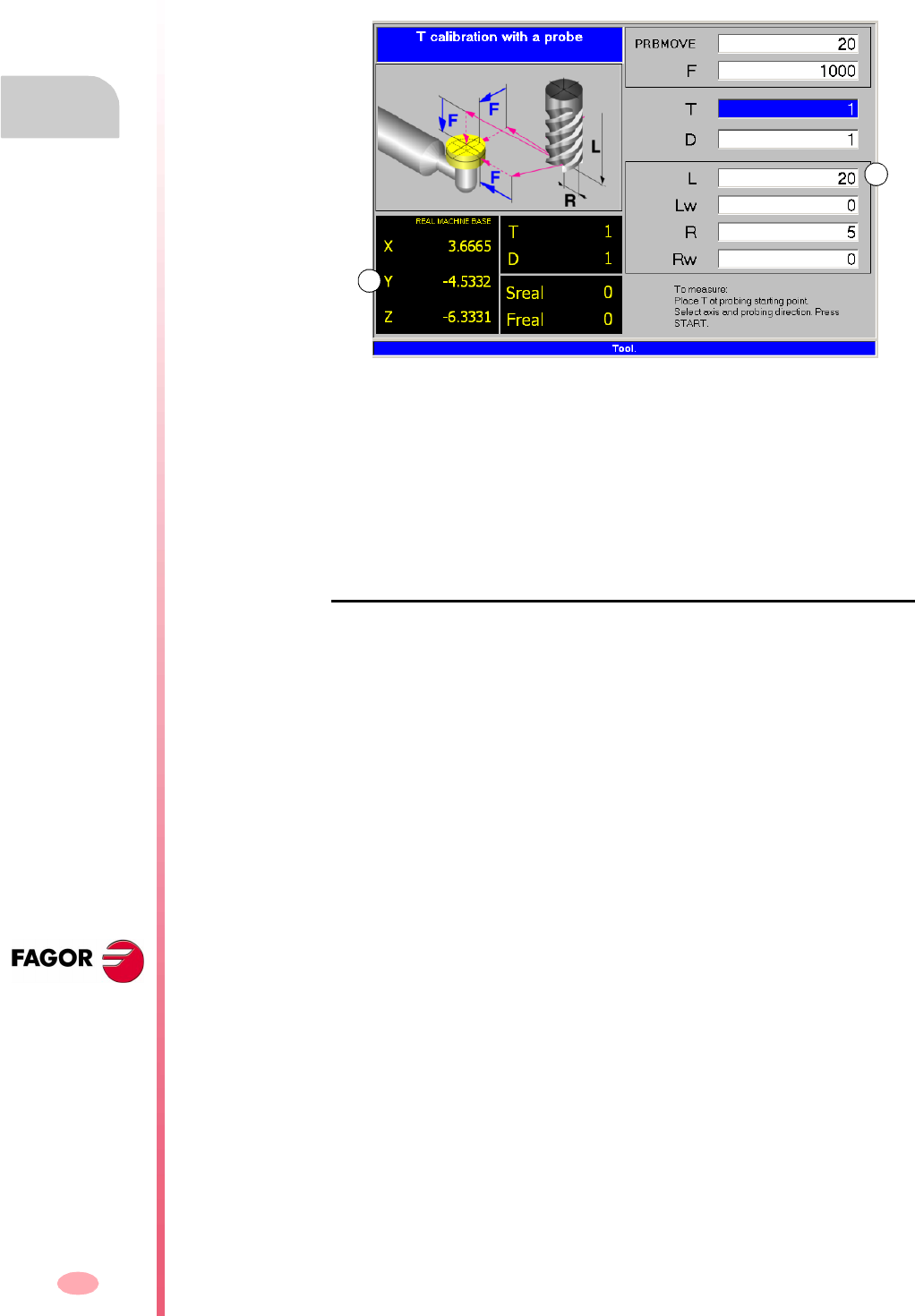
Operating manual
CNC 8070
5.
MANUAL (JOG) MODE. TOOL CALIBRATION
Semi-automatic calibration. Calibration with a probe
(SOFT V03.0X)
84
5.2 Semi-automatic calibration. Calibration with a probe
This option is only available when using a tabletop probe installed on the machine.
In this mode, only milling tools can be calibrated.
A. Machine data. Position of the axes, tool and active tool offset, real spindle speed
and real feedrate of the axes.
B. Area to define the calibration data.
It may be used to calibrate the length or the radius of the tool that is currently in the
spindle. After the calibration, the wear is reset to zero.
When changing the tool data, the tool table data is updated after calibration.
Tool calibration
The calibration consists in manually approaching the tool to the probe and then
command the CNC to execute the probing movement. The CNC will move the tool
on the selected axis until touching the probe. After touching the probe, it concludes
the calibration on that axis and updates the values.
Selecting a tool
The tool and the active tool offset may be changed from the calibration mode. After
defining the new tool or tool offset in the cycle data, press [CYCLE START] and the
CNC will execute the tool change.
Bear in mind that in this calibration mode, the [CYCLE START] key has two functions.
If a new tool has been selected, it executes the tool change. If the selected tool is the
active one, pressing [CYCLE START] initiates the calibration.
Tool calibration
In this mode, only milling tools can be calibrated. For these tools, the length and radius
may be calibrated. After calibrating one of the two dimensions, its wear value is reset
to zero.
Use the horizontal softkey menu to select the axis and the moving direction for the
calibration. Once selected and after placing the tool in the spindle, press [CYCLE
START] to start the calibration. The tool will move in the indicated direction until
touching the probe and it will then conclude the calibration updating the tool data with
the measured values.
Once a movement has been selected, the window will show a help drawing indicating
the type of calibration to be done, length or radius.
B
A

Operating manual
CNC 8070
MANUAL (JOG) MODE. TOOL CALIBRATION
Semi-automatic calibration. Calibration with a probe
5.
(SOFT V03.0X)
85
Definition of data
To define the data, place the focus on the relevant data, key in the desired value and
press [ENTER].
Tool calibration steps
To calibrate the tool, follow these steps:
1. Define the probing distance and feedrate.
If the feedrate is not defined, the probing movement will be made at the feedrate
set by the OEM.
2. Select the tool and the offset to be calibrated. After the selection, the CNC shows
the dimensions defined in the tool table for that offset.
To calibrate a tool, it must be the active tool. When selecting a tool and pressing
[ENTER], the CNC only shows the data for that tool. Press [CYCLE START] for
the CNC to make the tool change so it becomes the active tool. See "Tool
calibration" on page 84.
3. Manually approach the tool to the probe until it is placed on the path that will be
used for probing.
To calibrate the radius with a cylindrical probe, the path must coincide with the
probe's center point; if not, the radius will be calculated wrong.
4. Calibrate the tool. Select the axis and the probing direction on the softkey menu
and press [START].
The probe moves in parallel to the axis and in the selected direction until touching
the probe. It updates the measured value and resets the wear value to zero. The
data is stored in the tool table.
Data Meaning
PRBMOVE Maximum probing distance. If the CNC does not receive the probe
signal before reaching moving this probing distance, it stops the
axes.
F Probing feedrate.
T Tool to be calibrated.
D Tool offset to be calibrated.
L Tool length.
Lw Length wear.
R Tool radius.
Rw Radius wear.
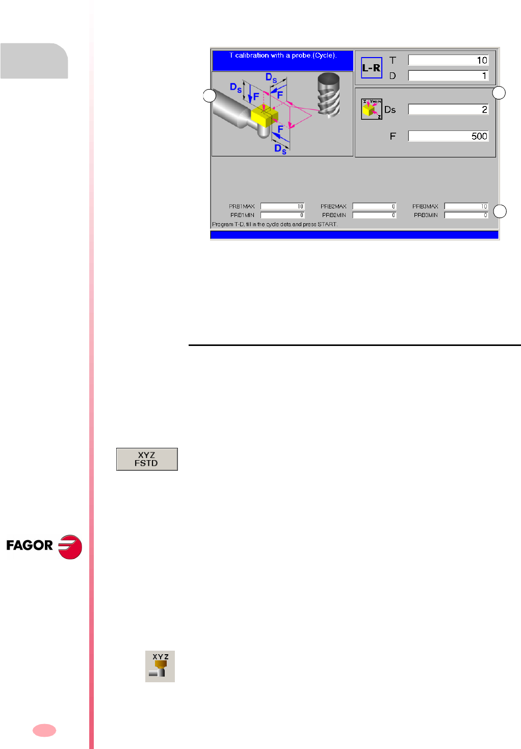
Operating manual
CNC 8070
5.
MANUAL (JOG) MODE. TOOL CALIBRATION
Automatic calibration with a probe and a canned cycle
(SOFT V03.0X)
86
5.3 Automatic calibration with a probe and a canned cycle
5.3.1 Mill or lathe model ("trihedron" geometrical configuration)
This option is only available when using a tabletop probe installed on the machine.
This mode may be used to calibrate both milling and lather tools. The CNC will show
the necessary data and will update the help graphics according to the selected tool.
A. Machine data is optionally shown. Position of the axes, tool and active tool offset,
real spindle speed and real feedrate of the axes.
B. Area to define the calibration data.
C. Probe position.
Tool calibration
The calibration is done using a probing canned cycle. The CNC moves the tool until
touching the probe and validates the calibration on each axis. The tool may be
calibrated on both axes of the plane or on the three axes of the trihedron.
The calibration begins when pressing the [CYCLE START] key. When the CNC
finishes the calibration on the selected axes, it updates the dimensions and the wears.
Them, the new values are saved in the tool table.
Selecting a tool
In this calibration mode, the cycle itself changes the tool and the tool offset. There
is no need to previously place the tool in the spindle.
Bear in mind that pressing the [CYCLE START] key starts the calibration cycle.
Select another position for the probe
The calibration uses the probe position defined in the machine parameters.
Optionally, another position may be defined for the probe which will only be valid for
the defined calibration. The new position does not affect the values defined in the
machine parameters.
AB
C
The horizontal softkey menu offers the option to show the machine data such as
position of the axes, feedrate, etc. This data is shown on the help graphics of the
window.
The data for defining the new probe position is accessed using the vertical softkey
menu.
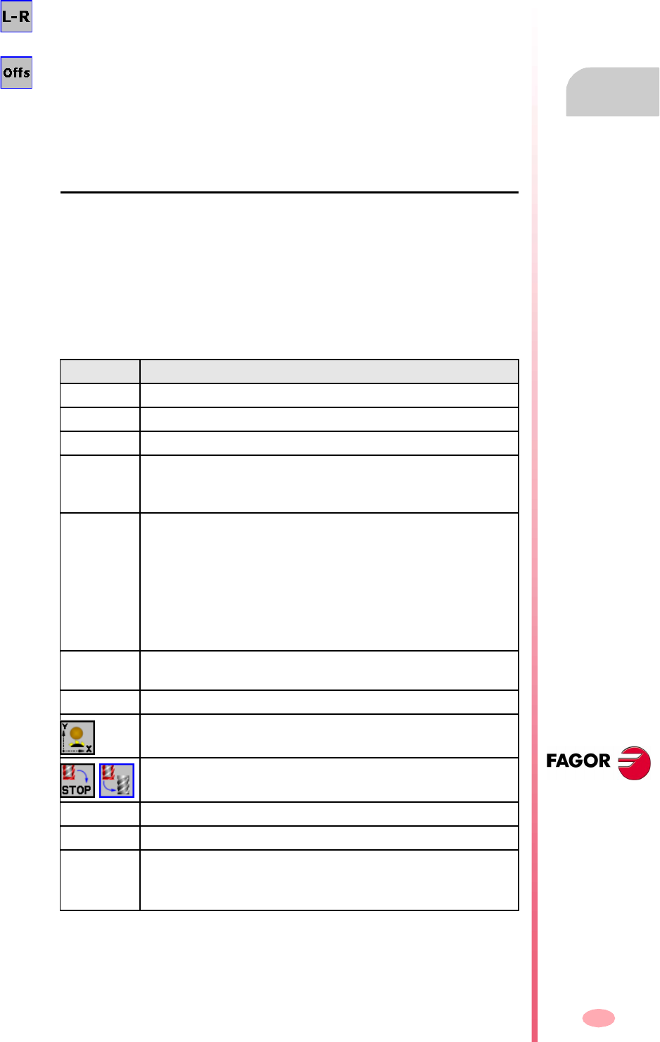
Operating manual
CNC 8070
MANUAL (JOG) MODE. TOOL CALIBRATION
Automatic calibration with a probe and a canned cycle
5.
(SOFT V03.0X)
87
Tool calibration
There are two options for the milling tools and may be selected with the following
icons.
For the lathe tools, it calibrates the tool offsets on each axis. The offset wears are
set to zero.
Definition of data
To define the data, place the focus on the relevant data, key in the desired value and
press [ENTER]. To change icons, place the focus on it and press [SPACE].
To calibrate the length, radius and wears of a milling tool.
The data shown depends on the calibration option selected with the horizontal softkey
menu. This menu may be used to select the length and/or radius calibration and
whether to calculate their wear or not. If the wears are not calculated, they are reset
to zero after the calibration.
•Calibrate the offsets and resets the wears to zero.
•Calibrate the length and radius and measure the wears.
Data Meaning
T Tool to be calibrated.
D Tool offset to be calibrated.
Ds Safety distance.
F Probing feedrate.
If not defined, the movements are carried out at the default feedrate,
set by the machine manufacturer.
N Number of cutters of the tool.
If defined with a ·0· value, the CNC knows the location of a cutter and
it will only make the movement once. The spindle turning speed must
be ·0·.
If defined with a value other than ·0·, all cutters will be calibrated. The
CNC makes an initial movement to locate a cutter; then, stops the
spindle and makes a precise measurement of each cutter. It is
necessary to define the spindle speed and the Dm distance.
Dm Distance the edge of the tool separates from the center of the probe
to position the next cutter.
S Spindle speed.
Probe side to be touched.
Behavior when exceeding the maximum wear permitted; reject the
tool or change it with another one from the same family.
Lw Maximum length wear allowed.
Rw Maximum radius wear allowed.
PRB1MAX
···
PRB2MIN
Probe position.
The values defined here are only taken into account during the
calibration cycle; they do not modify the machine parameter values.
Operating manual
CNC 8070
5.
MANUAL (JOG) MODE. TOOL CALIBRATION
Automatic calibration with a probe and a canned cycle
(SOFT V03.0X)
88
To calibrate the offsets of a milling or lathe tool.
Tool calibration steps
To calibrate the length, follow these steps.
1. Select the tool and the offset to be calibrated. It is not necessary to insert the tool
into the spindle; the CNC carries out this operation if necessary.
2. Define the data defining the calibration. To calibrate a milling tool, use the
horizontal softkey menu to select the desired operation.
3. Press the [CYCLE START] key to start the calibration. The CNC calibrates the
tool making all the necessary movements; there is no need to manually approach
the tool. If necessary, the CNC makes the tool change.
4. After the calibration It updates the tool table data.
Data Meaning
T Tool to be calibrated.
D Tool offset to be calibrated.
Ds Safety distance.
F Probing feedrate.
If not defined, the movements are carried out at the default feedrate,
set by the machine manufacturer.
PRB1MAX
···
PRB2MIN
Probe position.
The values defined here are only taken into account during the
calibration cycle; they do not modify the machine parameter values.
This icon sets the number of axes to calibrate on.
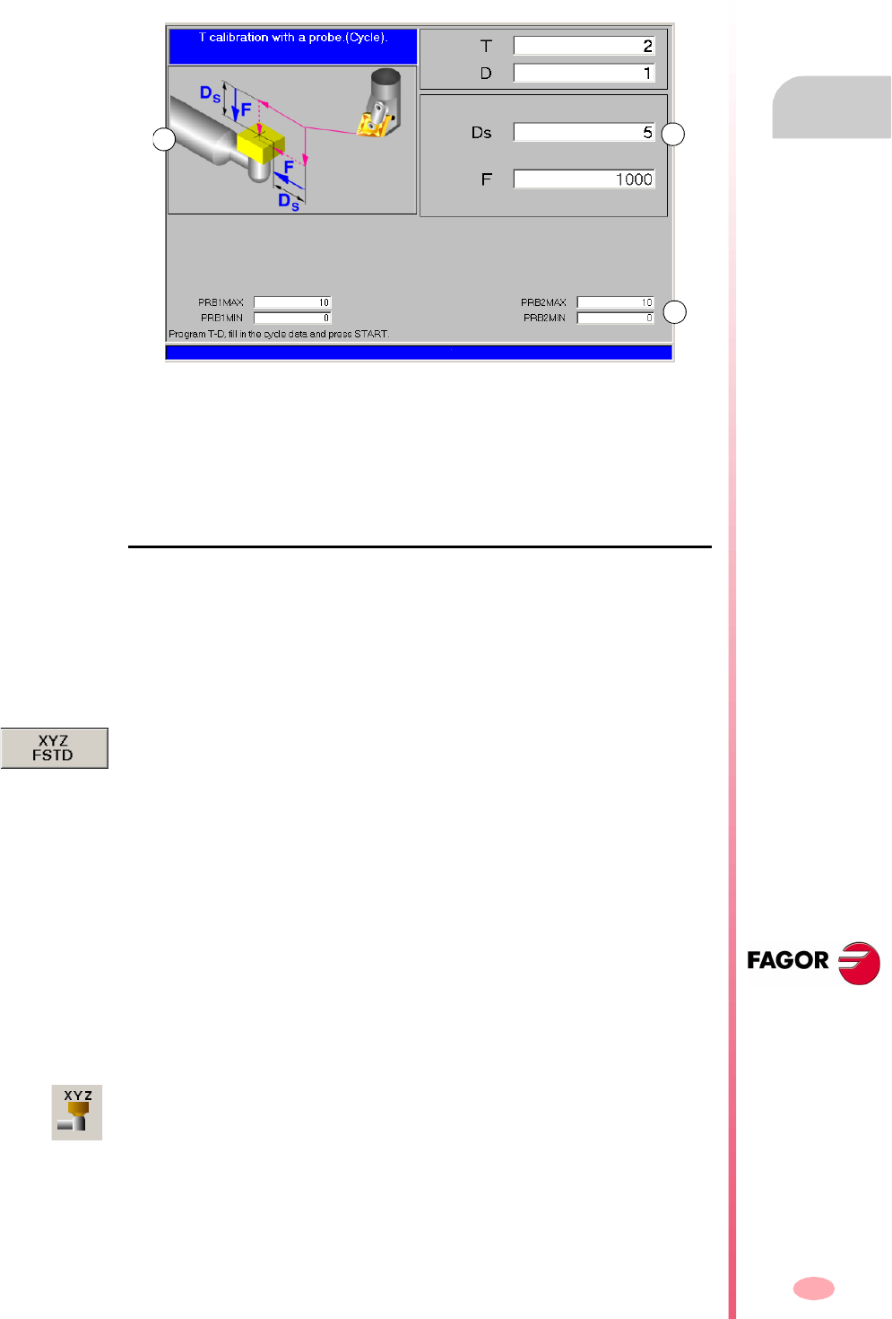
Operating manual
CNC 8070
MANUAL (JOG) MODE. TOOL CALIBRATION
Automatic calibration with a probe and a canned cycle
5.
(SOFT V03.0X)
89
5.3.2 Lathe model ("plane" geometrical configuration)
This option is only available when using a tabletop probe installed on the machine.
This mode may be used to calibrate both milling and lather tools. The CNC will show
the necessary data and will update the help graphics according to the selected tool.
A. Machine data is optionally shown. Position of the axes, tool and active tool offset,
real spindle speed and real feedrate of the axes.
B. Area to define the calibration data.
C. Probe position.
Tool calibration
The calibration is done using a probing canned cycle. The CNC moves the tool until
touching the probe and validates the calibration on each axis. The tool is calibrated
on the two axes of the plane.
The calibration begins when pressing the [CYCLE START] key. When the CNC
finishes the calibration on the selected axes, it updates the dimensions and the wears.
Them, the new values are saved in the tool table.
Selecting a tool
In this calibration mode, the cycle itself changes the tool and the tool offset. There
is no need to previously place the tool in the spindle.
Bear in mind that pressing the [CYCLE START] key starts the calibration cycle.
Select another position for the probe
The calibration uses the probe position defined in the machine parameters.
Optionally, another position may be defined for the probe which will only be valid for
the defined calibration. The new position does not affect the values defined in the
machine parameters.
Tool calibration
For milling and lathe tools, it calibrates the tool offsets on each axis. The offset wears
are set to zero.
AB
C
The horizontal softkey menu offers the option to show the machine data such as
position of the axes, feedrate, etc. This data is shown on the help graphics of the
window.
The data for defining the new probe position is accessed using the vertical softkey
menu.
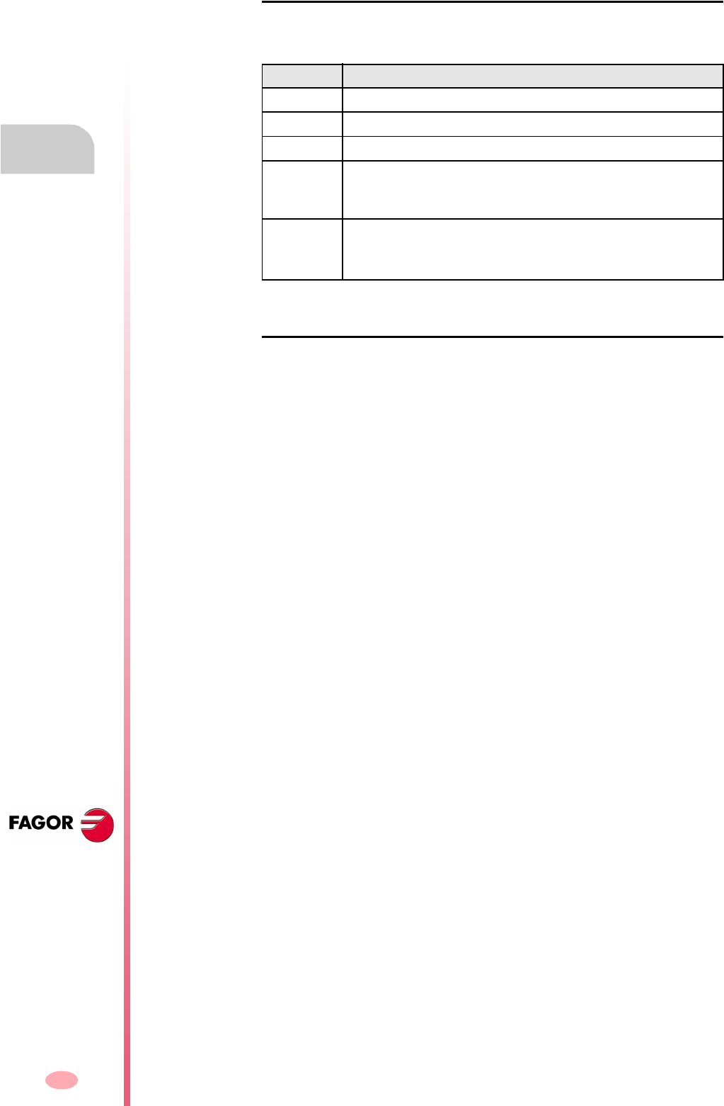
Operating manual
CNC 8070
5.
MANUAL (JOG) MODE. TOOL CALIBRATION
Automatic calibration with a probe and a canned cycle
(SOFT V03.0X)
90
Definition of data
To define the data, place the focus on the relevant data, key in the desired value and
press [ENTER]. To change icons, place the focus on it and press [SPACE].
Tool calibration steps
To calibrate the length, follow these steps.
1. Select the tool and the offset to be calibrated. It is not necessary to insert the tool
into the spindle; the CNC carries out this operation if necessary.
2. Define the data defining the calibration.
3. Press the [CYCLE START] key to start the calibration. The CNC calibrates the
tool making all the necessary movements; there is no need to manually approach
the tool. If necessary, the CNC makes the tool change.
4. After the calibration It updates the tool table data.
Data Meaning
T Tool to be calibrated.
D Tool offset to be calibrated.
Ds Safety distance.
F Probing feedrate.
If not defined, the movements are carried out at the default feedrate,
set by the machine manufacturer.
PRB1MAX
···
PRB2MIN
Probe position.
The values defined here are only taken into account during the
calibration cycle; they do not modify the machine parameter values.
91
CNC 8070
(SOFT V03.0X)
6
EDITING-SIMULATION MODE
Selecting the editing and simulation mode
This work mode may be accessed from any channel and even from several channels
at the same time. A different program may be edited and simulated in each channel.
What can you do in this work mode?
The following operations are possible in this work mode:
•Edit, modify or view the contents of a part-program.
A program may be edited in CNC programming language (ISO or high level) with
the assistance of a conversational editor for machining cycles and positioning
assisted by a profile editor or using the TEACH-IN feature.
•Simulate the execution of a program displaying a graphic representation of the
program being simulated.
•Estimate the total program execution time and the machining time for each tool.
The editing-simulation mode may be accessed from any other operating mode, even
while a program is in execution, by pressing the relevant key.

Operating manual
CNC 8070
6.
EDITING-SIMULATION MODE
Appearance of the editing - simulation
(SOFT V03.0X)
92
6.1 Appearance of the editing - simulation
When this operating mode is active, it will be indicated at the top right side of the
general status bar.
This mode may be displayed with several screens. The current screen and the total
number of available screens are shown at the upper right hand side of the general
status bar.
Switching between the different screens is done by pressing the editing-simulation
mode accessing key. The screen selection is rotary in such a way that when pressing
this key on the last screen, it shows the first one of the operating mode.
Standard configuration
The standard configuration of this work mode, described in this manual corresponds
to the one supplied by Fagor. In some cases, the manual shows a sample screen,
instead of that of the CNC in order to make it easier to understand.
These screens may be customized by the machine manufacturer changing its
contents as well as its appearance. They may also remove certain screens or add
some of their own.
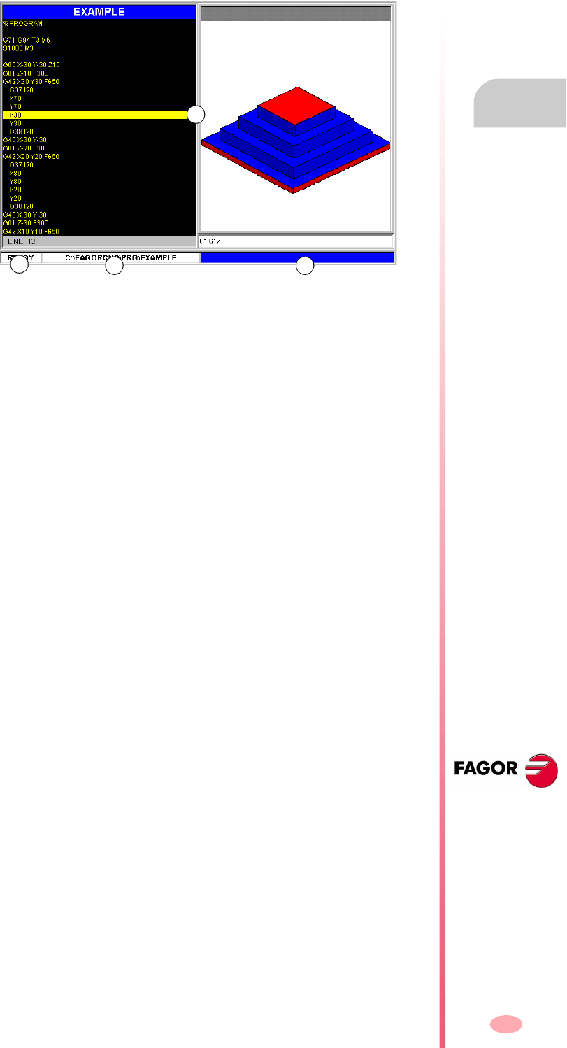
Operating manual
CNC 8070
EDITING-SIMULATION MODE
Appearance of the editing - simulation
6.
(SOFT V03.0X)
93
6.1.1 General screen description
On a typical screen for this work mode, the information is laid out as follows.
A. Windows of the editing-simulation mode.
It shows the operating windows of the selected screen. Every screen may consist
of one or more windows. See "6.1.2 Window description" on page 94.
B. Status of the program selected in this work mode or channel number when using
them.
In any case, the background color will be different depending on the status of the
program being simulated.
Ready Background color: White.
In simulation Background color: Green.
Interrupted Background color: Dark green.
In error Background color: Red.
C. Program name and location.
The background color will be different depending on the status of the program.
D. CNC messages.
A
BC D

Operating manual
CNC 8070
6.
EDITING-SIMULATION MODE
Appearance of the editing - simulation
(SOFT V03.0X)
94
6.1.2 Window description
As mentioned earlier, each screen may consist of one or many of the following
windows (later sections of this chapter describe each one of them in greater detail):
•Edit window: For editing new programs or modify the existing ones. Editing is
possible using a profile editor, a conversational canned cycle editor or using the
TEACH-IN feature.
•Graphic window: This window shows a graphic representation of the program
during the simulation. It also allows taking measurements on the graphics.
•Program window: For selecting the starting and ending conditions of the
simulation.
•Statistics window: For estimating the machining time for each tool and the total
program execution time.
When the screen consists of several windows, the softkey menu will show the options
of the active window. To switch windows and access the desired softkey menu, press
the relevant key.
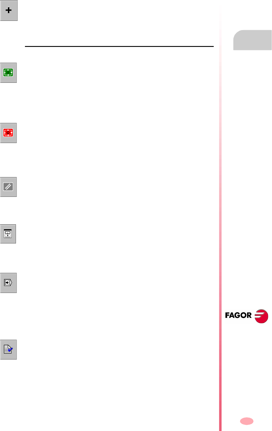
Operating manual
CNC 8070
EDITING-SIMULATION MODE
Appearance of the editing - simulation
6.
(SOFT V03.0X)
95
6.1.3 Icon description (vertical softkeys)
The icons are activated with their associated softkey (F8 to F12).
List of icons
The icon menu always shows all the icons related to this operating mode regardless
of which window is active. The group of options shown on this menu may be expanded
with the softkey associated with the "+" icon that offers a different set of options.
START (simulation)
(This icon will not be available while simulating a program).
It starts the program simulation or resumes it if it was interrupted.
During simulation, the graphic window will show the graphic representation of the
program being simulated.
STOP (simulation)
(This icon will only be available when simulating a program).
It interrupts program simulation.
Simulation will resume by pressing the START icon.
RESET (simulation)
It cancels program simulation.
If an error occurs during simulation, it eliminates the error status and returns the
simulation mode to its initial conditions.
Channel change for the editing and simulation mode
(This icon will only be available when using channels).
It serves to change the channel being displayed for editing and simulation. It does
not affect the active channel at the CNC.
"Continuous" or "single block" mode
It selects the "single block" or "continuous" mode; either one may be selected even
while executing a program.
When "single block" mode is active (the icon will appear pressed), program simulation
will be interrupted at the end of each block. When the "automatic" mode is active, the
simulation will take place until the end of the program or up to the block selected as
end of simulation.
Check program syntax
It analyzes the program looking for syntax errors.
If there are no errors, the bottom of the screen will display a message indicating that
the program is correct. If there are syntax errors, they will be shown at the bottom
of the editing window.

Operating manual
CNC 8070
6.
EDITING-SIMULATION MODE
Appearance of the editing - simulation
(SOFT V03.0X)
96
Time estimates
(This icon is only available when the statistics window is displayed).
It offers an estimate of the total execution time at 100% of the programmed feedrate.
For this time estimate, the CNC analyzes:
•The machining and positioning time for each tool used in the program.
•The number of "M" functions that are executed.
•The number of tool changes performed.
The result will appear at the statistics window.
Simulation setup
It shows the simulation setup options.
•Activate and cancel tool radius compensation.
•Conditional stop.
•Activate and deactivate the software travel limits.
•Block skip condition.
•Cancel the channel synchronization in the simulation.
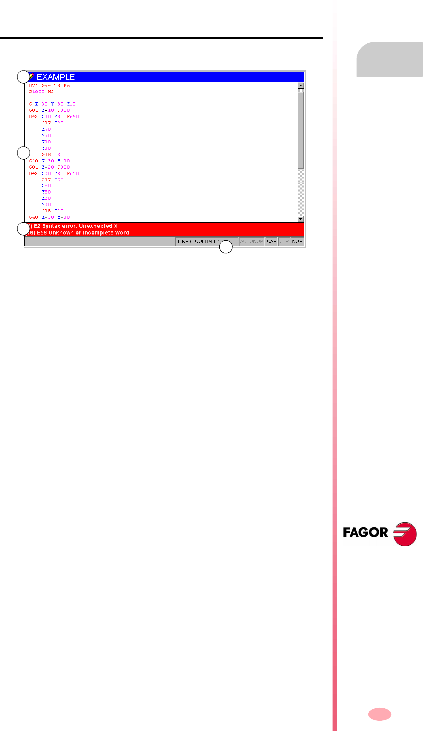
Operating manual
CNC 8070
EDITING-SIMULATION MODE
Editing window
6.
(SOFT V03.0X)
97
6.2 Editing window
It may be used to edit, modify or see the contents of a part-program and check the
program for syntax errors.
Description of the editing window
The editing window shows the following information:
A. Title bar
Name of the program selected for editing. It also indicates whether it is a read-
only program or not (if read-only, while simulating or executing).
An "*" next to the program means that the program has been modified since last
saved (only if automatic program saving is off).
B. Edit area.
Program editing area showing its contents.
C. Editing errors (if any).
List of errors occurred while editing the program or syntax errors found in the
syntax check.
D. Status bar.
Information about cursor position and the status of the editor options such as:
AUTONUM: Automatic block numbering. When active, the CNC automatically
numbers the new blocks being generated.
CAP: Capital letters. When active, the text is always written in capital
letters.
OVR: Overwrite text. It toggles between overwriting and inserting text.
When active, it overwrites the existing text.
NUM: Numeric keypad active.
B
C
D
A

Operating manual
CNC 8070
6.
EDITING-SIMULATION MODE
Editing window
(SOFT V03.0X)
98
Softkey menu of the editing window
When selecting the editing window, the horizontal softkey menu shows the options
for this window. The set of options offered by this menu may be changed using the
"+" softkey which offers a new set of options.
The options available in the softkey menu are the following. See "6.3 Editing
window (softkeys)" on page 102.
"Open program"
To select a program for the editing - simulation mode.
"File"
To restore, save, save with another name or print a program. It can also be used
to import the contents of another program, of a DXF file or PIM and PIT files.
"Undo"
To "undo" the last modifications made.
"Operations with blocks"
To copy, cut and paste information of a block or set of blocks within the program.
It can also copy a block or set of blocks as an independent program.
"Find/replace"
To search for a line or text in the program being edited. It can also replace a text
with another text.
"Customize"
To customize the appearance and the properties of the editing window.
"Profile editor"
To access the profile editor and define a new profile or modify an existing one.
"Cycle editor"
To access the conversational editor for machining and positioning canned cycles.
"TEACH-IN ON / TEACH-IN OFF"
To turn on or off the TEACH-IN mode.

Operating manual
CNC 8070
EDITING-SIMULATION MODE
Editing window
6.
(SOFT V03.0X)
99
6.2.1 Program editing
The process of editing or modifying a program is the following:
1. Open the program at the editor or create a new program.
2. Use the cursor to select the block where the new blocks will be inserted. Edit the
program blocks using the editing modes available.
3. Save the program so it can be modified or executed later on. This operation may
be performed automatically as the program is being edited or if the editor has been
personalized.
Available editing modes
Any of the various editing modes available may be used while editing a program. The
available editing modes are:
CNC language
It is edited block by block and each one may be written in ISO language or in High
level language.
When editing high level commands and depending on the type of command, the editor
offers a list of available commands.
•Keying in "V" shows the list of CNC variables.
•Keying in "#" shows the list of CNC instructions.
•Keying in "$" shows the list of flow control instructions of the CNC.
In all of them, when keying the following letter of the variable or instruction name, the
cursor of the list goes to the first command that starts with that letter. The [©][ª] keys
may be used to move the cursor through the list of commands and the [ENTER] key
to enter the selected command into the block that is being edited.
Conversational editor for canned cycles
To define machining and positioning canned cycles quickly and easily. This mode
offers the following advantages:
•There is no need to know the canned cycle parameters.
•The CNC only lets entering the data being shown, thus avoiding any data entry
errors when defining the cycles.
•The programmer is assisted at all times with help messages.
When done editing the cycle, the CNC generates the necessary blocks and it will add
them to the program inserting them after the block indicated by the cursor.
Profile editor
To edit new profiles quickly and easily. The editor shows a graphic representation of
the profile being defined.
After defining the profile data, the CNC generates the necessary blocks and it will add
them to the program inserting them after the block indicated by the cursor.
TEACH-IN
It is basically the same as editing in CNC language, except when it comes to
programming coordinates. This option displays the coordinates of each axis and lets
enter them directly into the block indicated by the cursor.

Operating manual
CNC 8070
6.
EDITING-SIMULATION MODE
Editing window
(SOFT V03.0X)
100
6.2.2 Import DXF files
DXF files may be imported from the editor to the program being edited. See
"6.3.2 File" on page 103.
The DXF format is standard for exchanging graphic files. Importing this type of files
makes it possible to generate the part-program directly from a drawing. The DXF file
may consist of points, lines and arcs. It can also consist of polylines, but they must
be previously uncombined.
When selecting this option, the CNC shows a list of the programs that may be
imported into the one being edited. Select the desired program from the list and press
[ENTER].
After selecting the file, define how the various layers of the DXF file are to be converted
into ISO code. Once this data has been set, press the "Convert" softkey to import the
file into the part-program.
DXF file configuration
When importing a DXF file, it shows the configuration window to define how the
different layers of the drawing must be treated. The configuration window shows three
areas clearly and distinctly.
Layer description area
The DXF files may consist of layers and each one has different heights of the drawing.
All the layers together make up the whole drawing.
When importing the file, you can decide which layers to include in the part-program.
By default, all the layers are included. To exclude a layer, select it and press the
"Disable layer" softkey.
For each layer, it indicates its priority and offset (height) on the perpendicular axis.
Layer priority and offset
It shows the data of the layer selected by the cursor. For each layer, one must define
its priority and offset (height) on the perpendicular axis.
•The priority defines the order in which the layers will be executed; i.e. the order
in which they will be included in the part-program. Those with priority ·1· will be
executed first and so on.
•The offset (height) on the perpendicular axis permits executing each layer in the
desired Z coordinate (or that of the relevant perpendicular axis).
Work plane
The work plane must be defined before importing the file in the part-program. The
plane is defined by selecting the abscissa axis, the ordinate axis and the
perpendicular axis.
When importing it in the profile editor, the plane will be the one selected at the editor
and only the perpendicular axis can be selected.
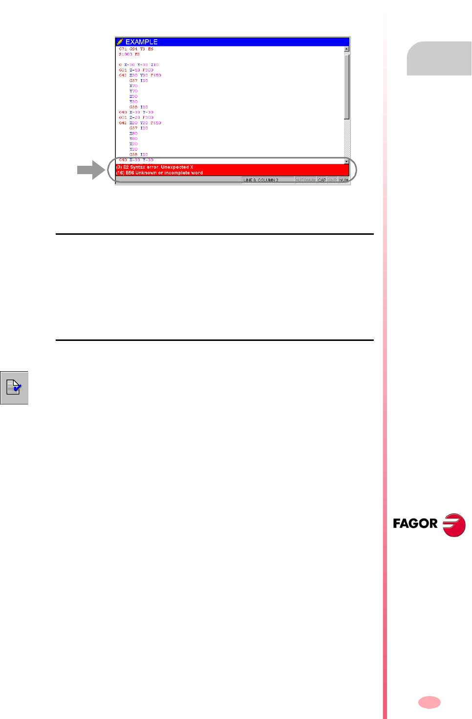
Operating manual
CNC 8070
EDITING-SIMULATION MODE
Editing window
6.
(SOFT V03.0X)
101
6.2.3 Syntax errors when editing
The syntax errors occurred while editing or after running a syntax check will be
displayed at the bottom of editing window.
To toggle the cursor between the editor and the error listing, press the key
combination [CTRL]+[TAB].
Errors while editing
While editing, each block is analyzed when entered. If a syntax error is detected in
the block, the error window will display the following information:
•Position of the error in the block.
•Error number and explanatory text.
Errors after a syntax check
•Location and name of the program being checked.
•Line number and position of the error within the block.
•Explanation of the error.
Moving the cursor through the errors of the window, the editor will highlight the block
containing the selected error. Press [ENTER] to select the block containing the error
or press [ESC] to close the error window.
The syntax check is executed from the icon menu.
The syntax check checks all the blocks of the program. If a syntax error is detected,
the error window will show the following information.

Operating manual
CNC 8070
6.
EDITING-SIMULATION MODE
Editing window (softkeys)
(SOFT V03.0X)
102
6.3 Editing window (softkeys)
6.3.1 Open program
To select a program for the editing - simulation mode. This program may be a new
one or an existing one. A different program may be edited and executed in each
channel.
When selecting this option, the CNC shows a list of the available programs. See
"2.5 File selection window" on page 22.
To select a program from the list:
1. Select the folder that contains the program. If it is a new program, it will be saved
in this folder.
2. Select the program from the list or write its name in the bottom window. To edit
a new program, write the name of the program in the bottom window.
3. Press [ENTER] to accept the selection and open the program or [ESC] to cancel
it and close the program listing.
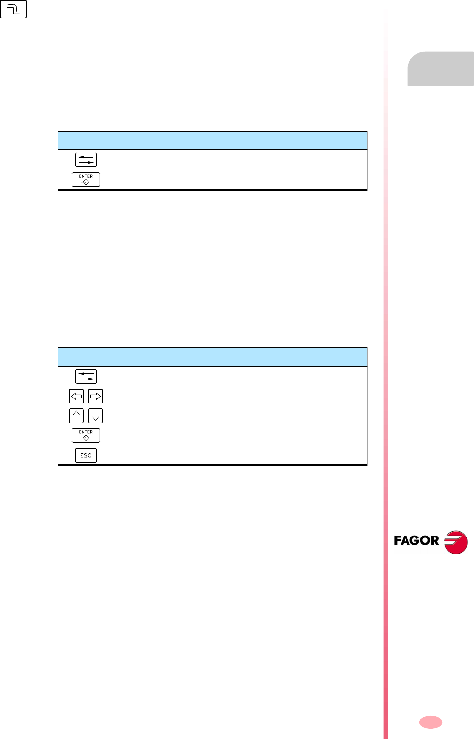
Operating manual
CNC 8070
EDITING-SIMULATION MODE
Editing window (softkeys)
6.
(SOFT V03.0X)
103
6.3.2 File
It is used to restore, save, import or print a program.
File "Restore original"
This option is only available when the "auto save" option is active. See
"6.3.6 Customizing" on page 107.
It is used to restore the original program without the changes made since the last time
it was opened. When selecting this option, the CNC requests confirmation of the
command:
File "Save"
This option is only available when the "Manual save" option is active. See
"6.3.6 Customizing" on page 107.
To save the program being edited.
File "Save as"
It is used for saving a program that is being edited with a different name. After saving
the program, one may continue editing the new program
When selecting this option, the CNC shows a list with all the programs already saved.
To save a program with another name:
1. Select the destination folder.
2. Write the program name in the bottom window. To replace an existing program,
select it from the list
3. Press [ENTER] to save the program or [ESC] to return to the editor without saving
the program.
Once the program has been saved, the top of the editing window will show the name
of the new program.
When selecting this option, the softkey menu shows the available options. To return
to the main menu, press the key for the previous menu.
Keys to move the cursor
Moves the cursor through the selection buttons.
Applies the option selected with the cursor.
Keys for selecting a file
To switch windows.
To close and open a folder submenu.
To move the cursor thru the elements of the window.
To save the new program.
To cancel the selection and close the program listing.
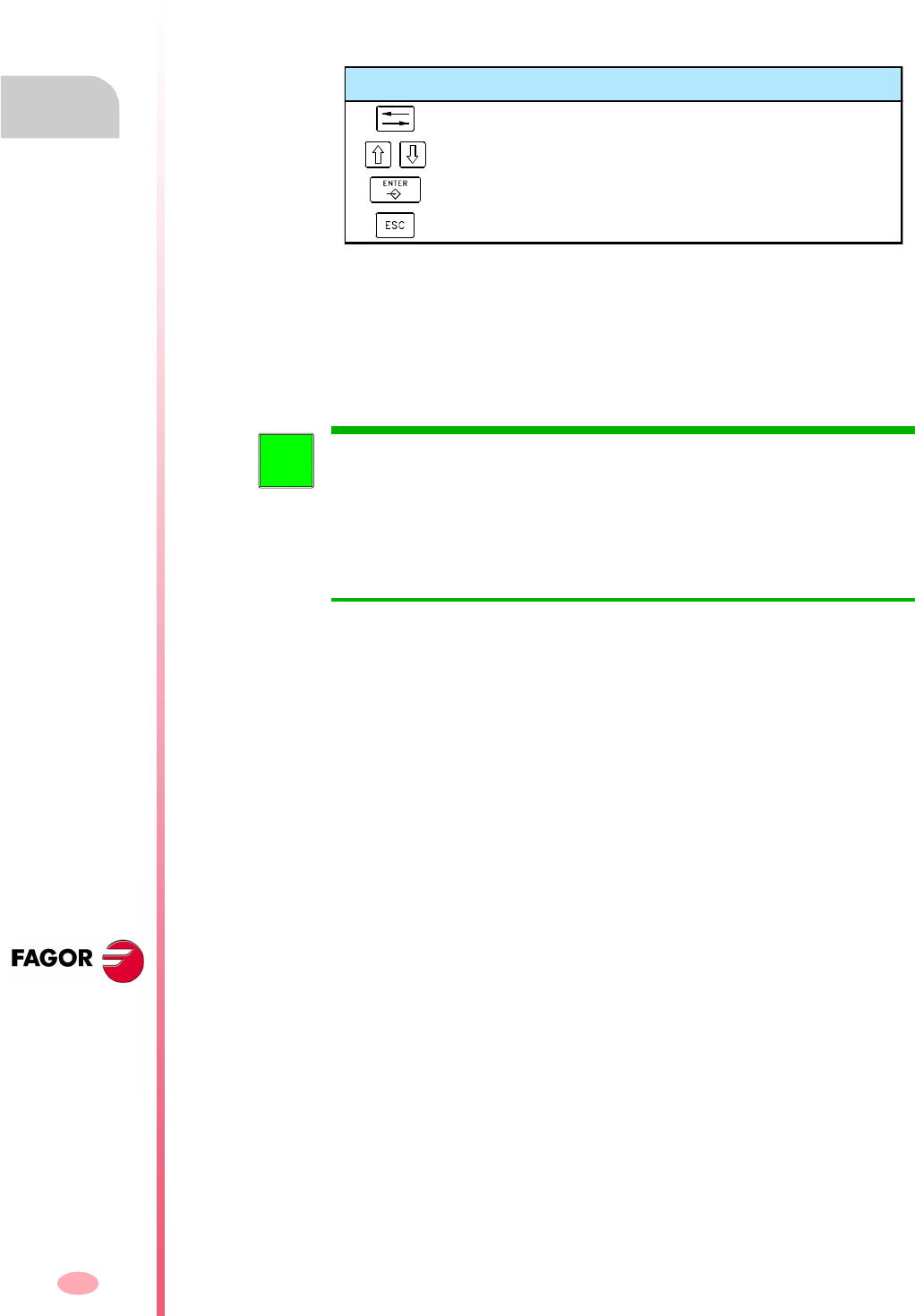
Operating manual
CNC 8070
6.
EDITING-SIMULATION MODE
Editing window (softkeys)
(SOFT V03.0X)
104
File "Include program"
It may be used to import the content of a part-program into the one being edited. Any
program that may be accessed from the CNC may be imported, even the program
currently in execution.
When selecting this option, the CNC shows a list of the programs that may be
imported into the one being edited.
To import a program from the list:
1. Select the desired program from the list or write its name in the bottom window.
2. Press [ENTER] to import the program or [ESC] to cancel the selection and close
the program listing.
The selected program is added to the one being edited after the block indicated by
the cursor.
File "Print"
It is used to print the program that is being edited out to a printer connected to the
CNC.
File "Import"
It permits importing DXF, PIM and PIT files into the program being edited. See
"6.2.2 Import DXF files" on page 100.
•The DXF format is standard for exchanging graphic files. Importing this type of
files makes it possible to generate the part-program directly from a drawing. The
files must consist of points, lines and arcs.
•PIM and PIT files are part-programs used by the 8055 CNC. When importing this
type of file, its programming language is adapted to the one used by the CNC.
When selecting this option, the CNC shows a list of the programs that may be
imported into the one being edited. Select the desired program from the list and press
[ENTER].
6.3.3 Undo
To "undo" the last modifications made. The modifications are undone one by one
starting from the most recent one.
Keys for selecting a program
To switch windows.
To move the cursor thru the elements of the window.
To save the new program.
To cancel the selection and close the program listing.
The program may be selected from the list as follows:
• By moving the cursor to the desired element.
• Using the alphanumeric keyboard. Pressing a key will select the first
element from the list starting with that letter or number. Pressing it again
will select the second one and so on.
Programs may also be selected using the "File search" option of the softkey
menu.
i
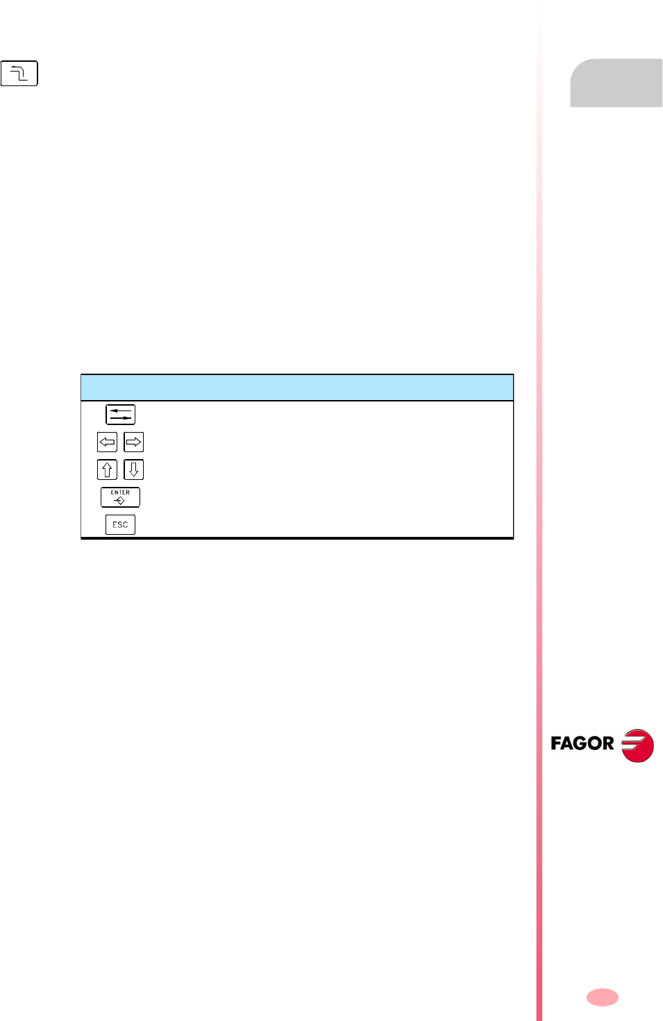
Operating manual
CNC 8070
EDITING-SIMULATION MODE
Editing window (softkeys)
6.
(SOFT V03.0X)
105
6.3.4 Operations with blocks
It is used to copy, cut and paste the information of a block or set of blocks and export
this information as an independent program.
This option is only available when there is a text selected in the program or on the
clipboard. To select a text in the program, keep the [SHIFT] key pressed while moving
the cursor.
Operations with blocks "Copy"
It copies the selected text onto the clipboard.
Operations with blocks "Cut"
Copies the selected text onto the clipboard and deletes it from the program.
Operations with blocks "Paste"
Pastes the contents of the clipboard into the program.
Operations with blocks "Copy to program"
Saves the selected texts as an independent program.
When selecting this option, the CNC shows a list of the available programs.
To save the text as a program:
1. Select the destination folder.
2. Write the program name in the bottom window. To replace an existing program,
select it from the list.
3. Press [ENTER] to save the program or [ESC] to cancel the selection and close
the program listing.
When selecting this option, the softkey menu shows the available options. To return
to the main menu, press the key for the previous menu.
Keys for selecting a program
To switch windows.
To close and open a folder submenu.
To move the cursor thru the elements of the window.
To import the selected program.
To cancel the selection and close the program listing.
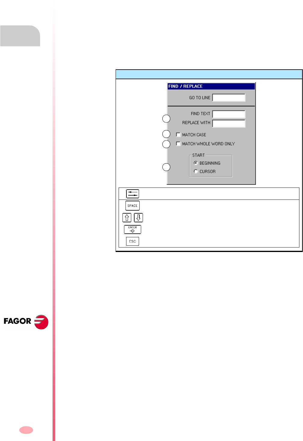
Operating manual
CNC 8070
6.
EDITING-SIMULATION MODE
Editing window (softkeys)
(SOFT V03.0X)
106
6.3.5 Find/replace
It is used for searching for a line or a text in a program. It can also replace a text with
another text.
When selecting this option, the CNC shows a dialog box requesting the line number
or the text to look for. When defining a text search, certain options may also be defining
that allow:
A. Replacing the text being searched with another in the program.
B. Ignore uppercase and lowercase.
C. Consider the text to find as a whole word.
D. Select whether the search starts at the beginning of the program or at the cursor
position.
After defining the search options, press [ENTER] to start the search or [ESC] to cancel
it.
The text found in the program will be highlighted and the softkey menu will show the
following options:
•Replace, to replace the highlighted text.
•Replace all, to replace the text throughout the whole program.
•Find next, to skip this text and keep on searching.
To end the search, press [ESC].
Find/replace
To move the cursor through the elements of the list.
To activate/deactivate the selection box (B) (C).
To select an option of a group (D).
To start the search.
To cancel the search and close the dialog box.
A
B
C
D
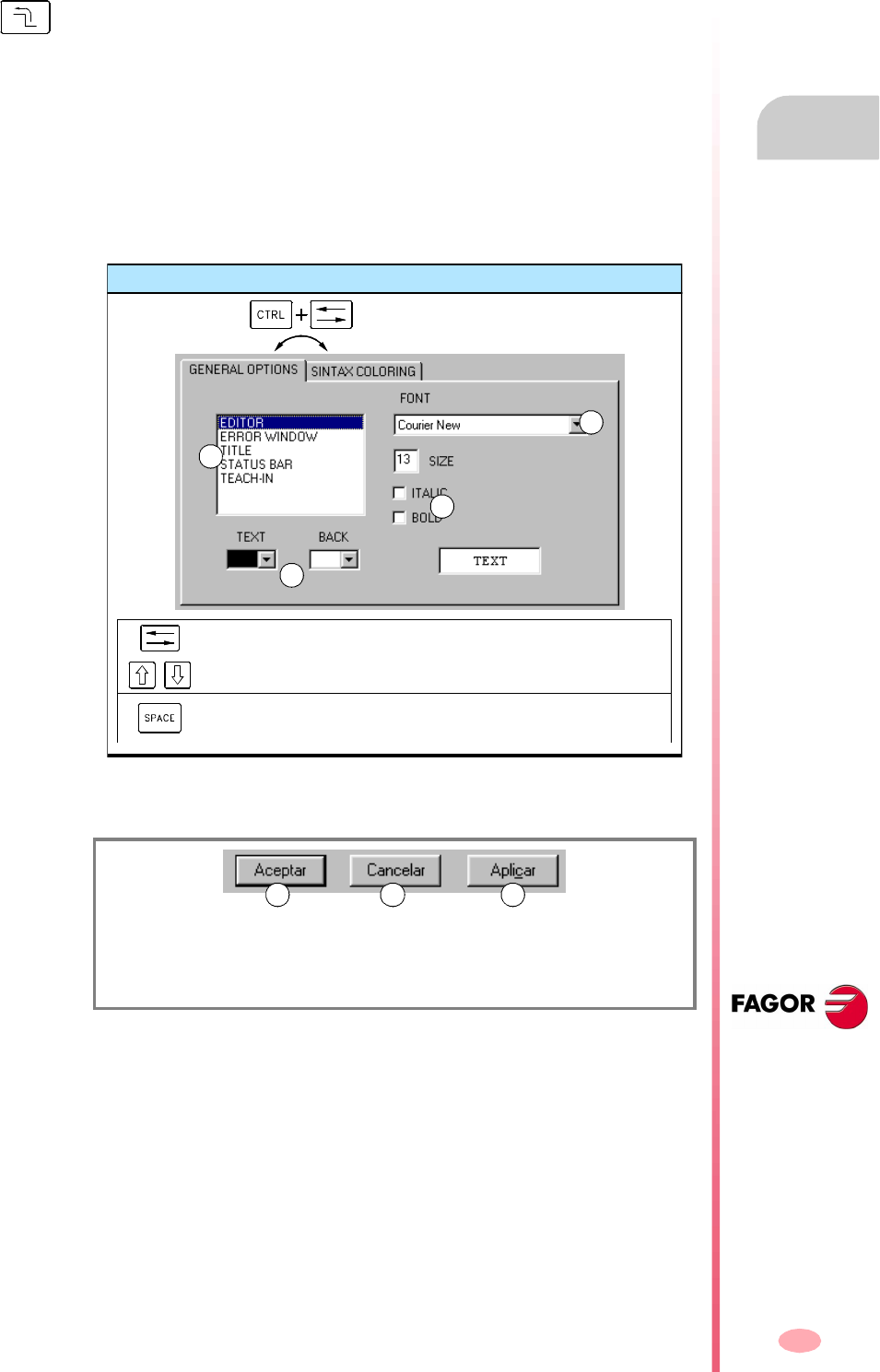
Operating manual
CNC 8070
EDITING-SIMULATION MODE
Editing window (softkeys)
6.
(SOFT V03.0X)
107
6.3.6 Customizing
To customize the appearance and the properties of the editing window.
Customizing "Appearance" (looks)
It is used for personalizing the look of the different elements of the editing window
and the colors of the elements of the program.
When selecting this option, the CNC shows the dialog box with two panels. The first
one has the elements of the editing window that may be customized and the second
one those of the program. The panel is selected by the key combination
[CTRL]+[TAB].
After defining the new look, use the cursor to select one of the buttons here below
to accept or ignore the changes made and press [ENTER].
The dialog box may also be closed directly without accepting the changes by pressing
[ESC].
Customizing "Auto-Save / Manual save"
It is used to save the program automatically or manually.
•When "auto-save" is on, the CNC will automatically save the program after every
change.
•If "Manual save" is active, it is up to the operator to save the program. See
"6.3.2 File" on page 103.
When selecting this option, the softkey menu shows the available options. To return
to the main menu, press the key for the previous menu.
(A) To accept the changes and close the dialog box.
(B) To ignore the changes and close the dialog box.
(C) To apply the changes and close the dialog box.
Set aspect
To move the cursor through the elements of the list.
To select an option of a group (A).
To turn on/off the checkboxes (C), and to open/close the drop lists
(B).
A
B
C
B
A CB

Operating manual
CNC 8070
6.
EDITING-SIMULATION MODE
Editing window (softkeys)
(SOFT V03.0X)
108
Customizing "Autonumbering ON / Autonumbering OFF"
It is used to turn on/off the autonumbering of the blocks. While autonumbering is
active, the CNC will insert the block number automatically every time a new block is
generated.
Customizing "Autonumbering parameters"
It is used for selecting the starting block number and the sequencing step for the
following blocks when autonumbering the blocks.
When selecting this option, the CNC shows a dialog box requesting both data. After
defining these values, press [ENTER] to accept them or [ESC] to ignore them.
Customizing "TEACH-IN parameters"
It may be used to set the behavior of each axis in TEACH-IN mode. The behavior of
an axis is defined by the properties "visible" and "selected".
Depending on these properties, one of the following behaviors may be assigned to
the axes:
•Selected and visible:
The axis is displayed in the TEACH-IN window and it is included in the blocks being
edited by pressing the [RECALL] key.
•Not selected and visible:
The axis is displayed in the TEACH-IN window, but it is not included in the blocks
being edited by pressing the [RECALL] key.
•Not selected and not visible:
The axis is neither displayed in the TEACH-IN window nor included in the blocks
being edited by pressing the [RECALL] key.
After defining the behavior of the axes, press [ENTER] to accept the selection or
[ESC] to reject it.
Show / Hide cycles and profiles
It is used for selecting whether the contents of the conversational canned cycles and
profiles will be shown or hidden in the program.
•If the "Show" option is active, it will show the full contents of the canned cycle and
the profile.
•If the "Hide" option is active, only the name of the canned cycle and the profile
will be shown.
"Visible" The axis is displayed in the TEACH-IN window.
"Selected" The axis is included in the blocks that are edited by
pressing the [RECALL] key.
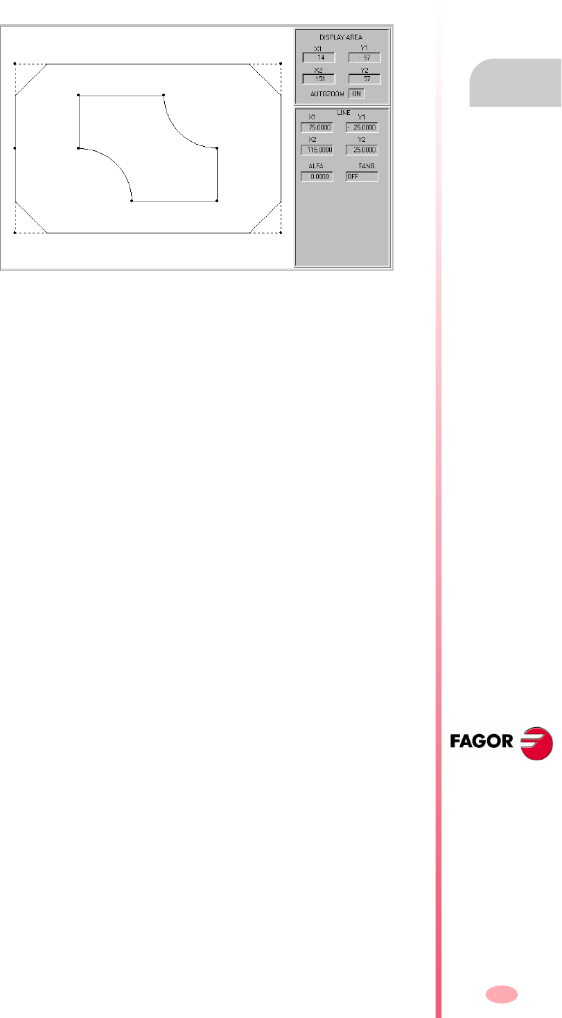
Operating manual
CNC 8070
EDITING-SIMULATION MODE
Editing window (softkeys)
6.
(SOFT V03.0X)
109
6.3.7 Profile editor
It is used for accessing the profile editor.
When selecting this option, the softkey menu shows the profile editor options. To
return to editing the program, press "End".
The profile editor may also be accessed by selecting a profile in the program and
pressing [RECALL].
The section on "6.9 Profile editor" of this chapter offers a more detailed description
on how to use the profile editor.
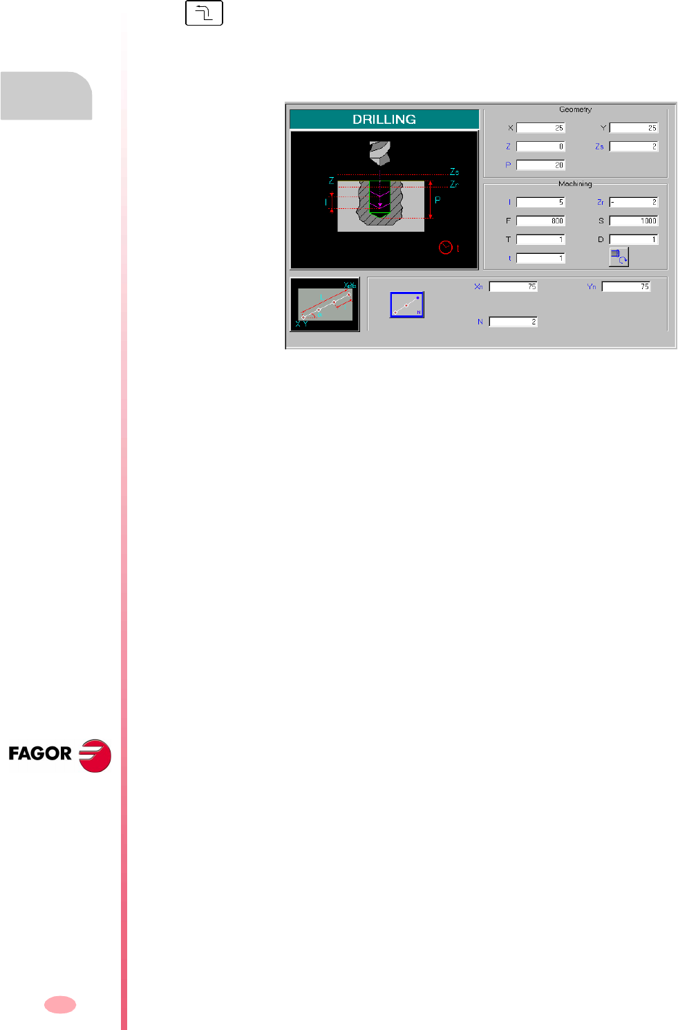
Operating manual
CNC 8070
6.
EDITING-SIMULATION MODE
Editing window (softkeys)
(SOFT V03.0X)
110
6.3.8 Canned cycles
It is used to access the conversational canned cycles.
When selecting a canned cycle, the CNC displays the window for defining that canned
cycle. Some of these canned cycles may be associated with multiple machining so
it is repeated at all points.
The cycle defining window may also be accessed by selecting a canned cycle in the
program and pressing [RECALL].
The cycle being edited may also be simulated in the window for defining the
conversational canned cycle.
The programming manual offers a more detailed description of how to define and/or
simulate conversational canned cycles.
When selecting this option, the softkey menu shows the available canned cycles. To
return to the main menu, press the key for the previous menu.
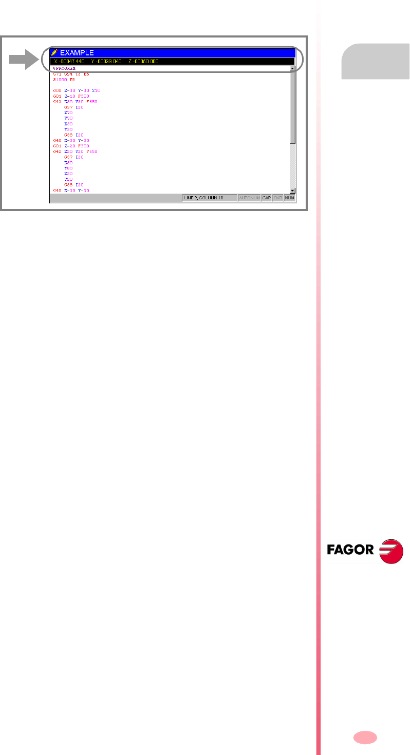
Operating manual
CNC 8070
EDITING-SIMULATION MODE
Editing window (softkeys)
6.
(SOFT V03.0X)
111
6.3.9 TEACH-IN ON / TEACH-IN OFF
It is used to activate or deactivate the TEACH-IN mode; in this mode, the axes may
be moved manually and their position may be assigned to a block.
When active, the top of the editing window shows the position of the axes defined as
“visible” for the TEACH-IN mode. See "6.3.6 Customizing" on page 107.
When TEACH-IN mode is active, it is possible to keep editing the coordinates of the
axes directly from the keyboard or they may be assigned the current position of the
machine axes. Both editing methods may be used indistinctly, even while defining a
block.
To define the coordinates of one or several axes using TEACH-IN:
1. Move the axes to the desired position using the JOG keys, the handwheels or the
MDI mode.
2. In the part-program, edit the name of the axes whose position is to be defined or
not select any axis if you wish to define the position of all of them.
3. Press the [RECALL] key.
•If an axis has been edited, the CNC assigns the current position of that axis
as the program coordinate. The axis is displayed in the TEACH-IN window.
•If no axis has been edited, a block is edited with the current position of all the
axes defined as “selected” for the TEACH-IN mode. See
"6.3.6 Customizing" on page 107.
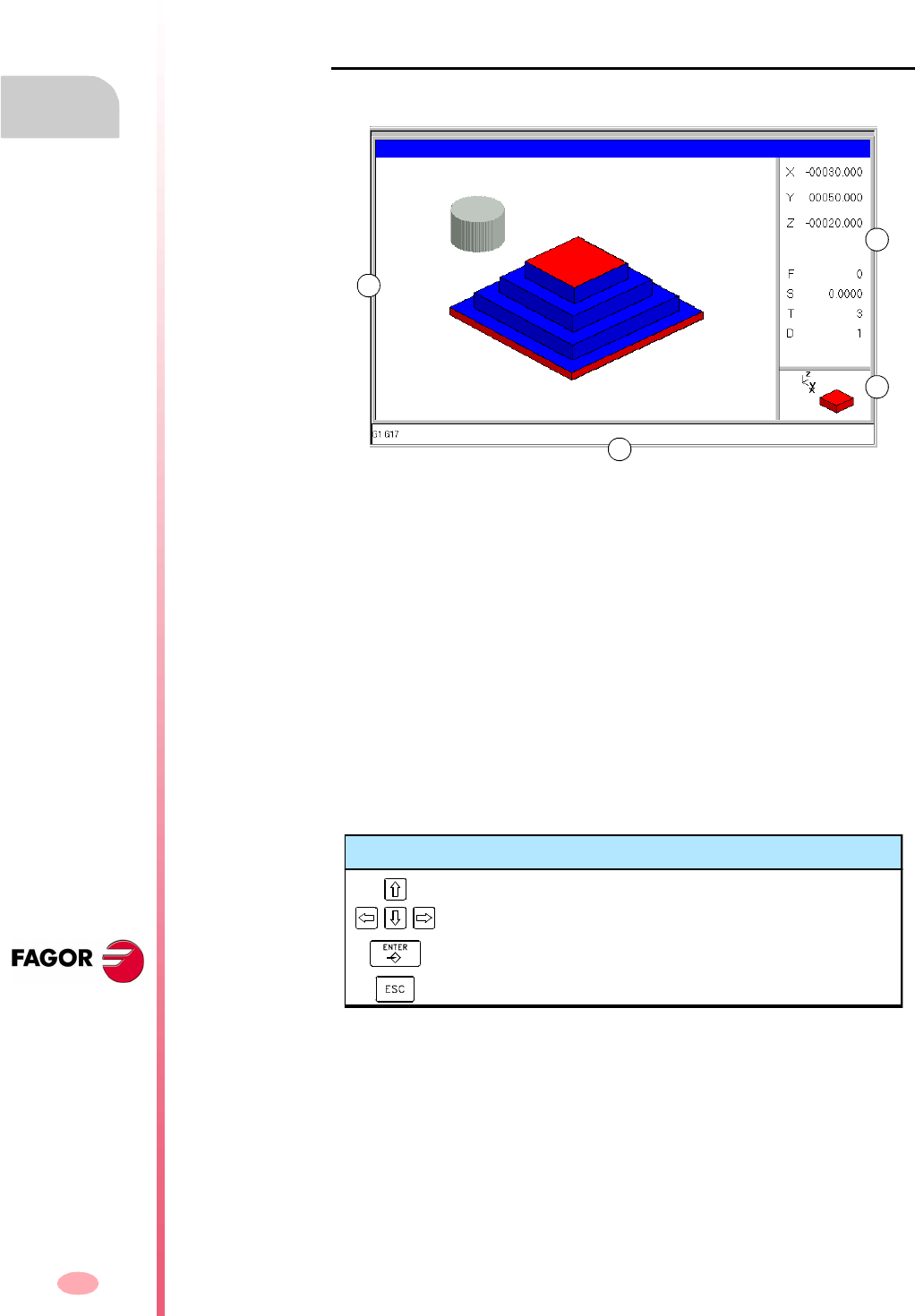
Operating manual
CNC 8070
6.
EDITING-SIMULATION MODE
Graphics window
(SOFT V03.0X)
112
6.4 Graphics window
It is used to show a graphic representation of the program being simulated and take
measurements over the drawing.
Description of the graphics window
The graphic window shows the following information:
A. Display area.
It shows a graphic representation of the tool paths or of the part as the program
is being simulated.
B. Dialog area.
It shows the position of the axes and the machining conditions active during
simulation (feedrate, spindle speed, tool and tool offset).
When selecting specific options of the softkey menu, it shows the information
associated with that option which may be defined by the user.
C. Information area.
Shows the work plane appearing in the display area and an illustration
representing the size of the graph and the portion of the graphic area selected
with the zoom.
On 3D graphics, the illustration shows the point of view of the graph displayed and
it may be changed by the operator.
D. "G" functions active during simulation.
A
B
C
D
Keys for selecting the point of view
Select a new point of view.
Assumes the new point of view selected.
Cancels the selected point point of view.

Operating manual
CNC 8070
EDITING-SIMULATION MODE
Graphics window
6.
(SOFT V03.0X)
113
Softkey menus of the graphics window
When selecting the graphic window, the horizontal softkey menu shows the options
associated with that window. The set of options offered by this menu may be changed
using the "+" softkey which offers a new set of options.
The options available in the softkey menu are the following. See "6.5 Graphic
window (softkeys)" on page 117.
"Type of graphics"
To select the type of graphics.
"ZOOM"
To enlarge or reduce the whole graph shown or part of it.
"Dimensions"
To define the size of the graphic representation.
"Point of view"
To change the point of view of the graph and show it from another perspective.
"Measurement"
To measure the distance between two points.
"Clear screen"
It is used to clear the screen or delete the graphics displayed.
"Colors"
To set the appearance of the graphics on display.
"Options"
To set the appearance and some options of the graphic window.
"Speed"
To change the simulation speed.
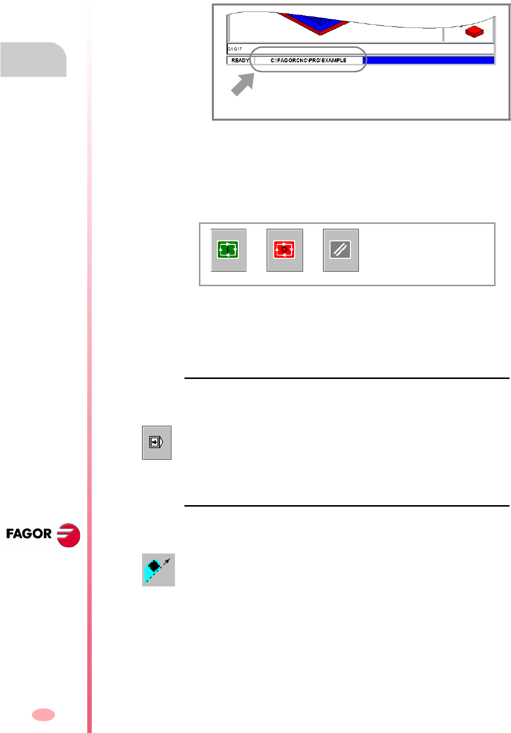
Operating manual
CNC 8070
6.
EDITING-SIMULATION MODE
Graphics window
(SOFT V03.0X)
114
6.4.1 Program simulation
The graphic window shows the program selected at the editing window and its name
appears at the bottom center of the screen.
The program simulation procedure is the following:
1. Choose the type of graphic representation, its dimensions and the point of view.
This data may also be modified during the simulation of the program.
2. Activate the desired simulation options using the icon menu.
3. Press the START icon to start the simulation. The simulation may be interrupted
with the STOP icon or canceled with the RESET icon.
The simulation of the program starts at the first block of the program and ends after
executing one of the end-of-program functions "M02" or "M30". As an option, it is
possible to define the first and last blocks of the simulation. See "6.6 Program
window" on page 126.
"Single block" mode of simulation.
If the –single block– mode is active, program execution will interrupted at the end of
each block; the [START] icon must be pressed again to continue.
Simulation options
The available simulation options are accessed from the icon menu. Pressing the icon
displays a window that shows the following options.
Program selected for simulation.
START STOP RESET
The –single block– mode is selected from the icon menu and may be selected before
or while simulating the program.
Tool radius compensation
It activates or cancels tool radius compensation to simulate the program.
Tool radius compensation being off, the simulation will ignore the programmed tool
radius compensation.

Operating manual
CNC 8070
EDITING-SIMULATION MODE
Graphics window
6.
(SOFT V03.0X)
115
Conditional stop during simulation
It simulates the external "conditional stop" switch.
While active, the program simulation will be interrupted at the blocks having a
"conditional stop" function "M01". The simulation will resume when pressing the
START icon.
Software limits
It activates or deactivates the software limits for program simulation.
With the limits activated, if the software limits are reached during simulation, a
simulation error message will be issued. If not active, the software limits will be
ignored during simulation.
Block jump
It simulates the external "block skip" switch.
While active, the blocks having the block-skip character "/" will be ignored (not
simulated).
Cancel channel synchronization
There is one icon for each channel. It cancels the channel synchronization wait
periods during simulation.
When active, the wait period will end immediately and it will resume the execution
of the program.

Operating manual
CNC 8070
6.
EDITING-SIMULATION MODE
Graphics window
(SOFT V03.0X)
116
6.4.2 Simulation errors
When an error occurs, the CNC will display a window describing the cause of the error.
These errors are displayed in the middle of the screen, regardless of which window
is active.
There are two types of errors. The top of the window shows the category and it will
have a different color depending on the type of error it shows.
WARNING
They do not interrupt the simulation of the program.
The window that shows them may be removed by pressing [ESC].
ERROR
They interrupt the simulation of the program.
Although the window displaying them may be closed by pressing [ESC], it does not
mean that the error status has been taken care of; to do that, press the [RESET] icon.
The program can be neither edited nor simulated while the error stays state active.

Operating manual
CNC 8070
EDITING-SIMULATION MODE
Graphic window (softkeys)
6.
(SOFT V03.0X)
117
6.5 Graphic window (softkeys)
6.5.1 Type of graphics
To select the type of graphics.
The various types of graphics may be line (3D lines, XY, XZ, YZ and Combined) or
solid (Sections and 3D solid). Line graphics show the tool path with lines of different
colors and solid graphics show an image of the part being simulated.
The type of graphics selected will remain active until another type is selected or the
graphic display is deactivated or the CNC is turned off. Likewise, when changing the
type of graphics, the CNC will maintain the graphic conditions (zoom, graphic
parameters, display area, etc.), defined for the last graphic.
"3D lines" Graphics
It displays a three-dimensional graph of the tool paths.
"Sections" Graphics
It displays a top view (XY plane) of the part being simulated; it shows the machining
depths in different tones. It also displays the XZ and YZ sections for the areas shown
by the indicators of the top view.
These indicators may be moved around using the [©][ª][§][¨] keys, to display the
different sections of the part. The CNC shows dynamically the new section being
selected.
The indicators may be moved at any time even while simulating the program.
"XY" - "XZ" - "YZ" graphics
It displays the tool paths in the XY, XZ or YZ plane.
"Combined" graphics
It divides the display area in four quadrants and displays the tool path corresponding
to each plane XY, XZ, YZ and to the 3D view.
"Solid 3D" Graphics
It shows a 3D view of the part being simulated. Starting out with a 3D block which
is "machined" as the program is simulated.
When selecting this option, the softkey menu shows the types of graphics available.
To return to the main menu, press the key for the previous menu.
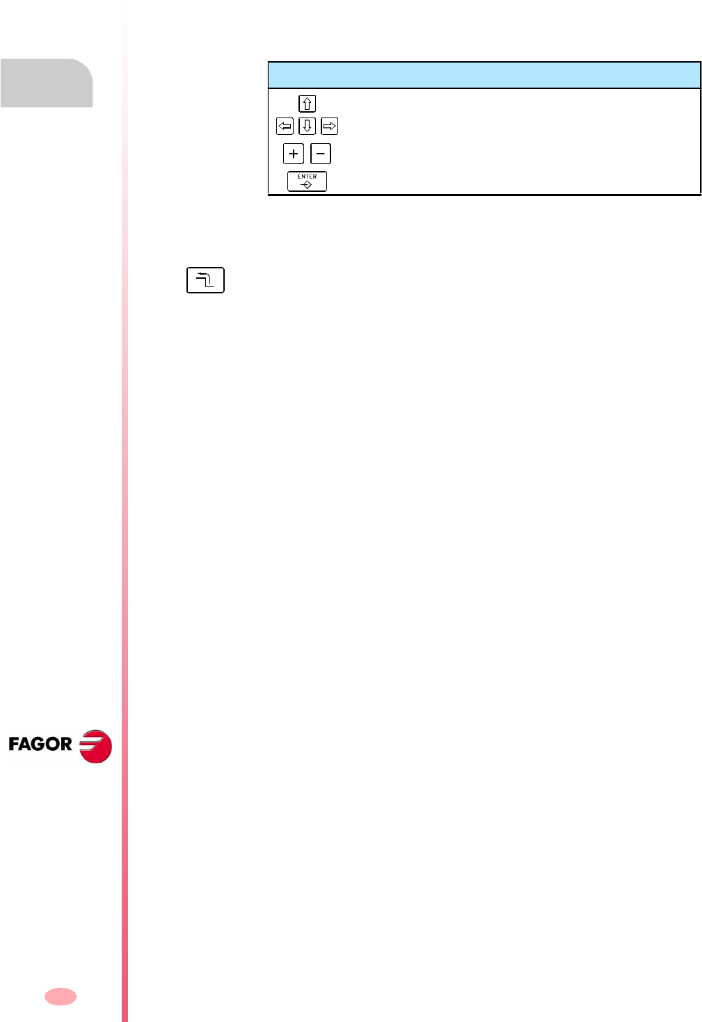
Operating manual
CNC 8070
6.
EDITING-SIMULATION MODE
Graphic window (softkeys)
(SOFT V03.0X)
118
6.5.2 Zoom
To enlarge or reduce the whole graph shown or part of it. This option is not available
in the "Combined" type of graphics.
After selecting the zoom option, a zoom frame will appear over the graphics. This
frame may be enlarged, reduced and moved around over the graphics already
displayed in order to select a particular portion of it to zoom into or out of.
The graphics at the lower right-hand side of the screen shows two figures. The one
shown with lines only, indicates the dimensions of the display area and the one with
colored sides indicates the portion selected with the zoom.
Zoom "Initial"
Restores the size of the display are set via program or using the "Dimensions" option.
Zoom "Automatic"
The CNC uses the zoom that it considers best according to the movements
programmed.
Zoom "Previous"
It displays up to two zooms defined earlier. After the second one, it shows again the
one defined last.
Zoom "Limits"
Only for the "Sections" type. In this graphics, zooming is done by moving the indicators
that appear framing the graphic sections.
With this option, it is possible to select the axis whose indicator is to be moved.
The indicator may also be selected with the "+" and "-" keys of the numeric keyboard
in a rotary fashion (Xmin, Xmax, Ymin, Ymax, Zmin, Zmax).
Keys for selecting the zoom
To move the zoom frame around.
To change the size of the zoom frame.
To validate and display the selected zoom area.
When selecting this option, the softkey menu shows the available zoom options. To
return to the main menu, press the key for the previous menu.
Operating manual
CNC 8070
EDITING-SIMULATION MODE
Graphic window (softkeys)
6.
(SOFT V03.0X)
119
Zoom "Edit"
It is used to manually edit the zoom values. It is edited in the dialog area of the graphic
window that shows the dimensions of the zoom frame
Keys for defining the zoom
To move the cursor through the data.
To validate and display the defined zoom area.
To cancel the defined zoom.
Operating manual
CNC 8070
6.
EDITING-SIMULATION MODE
Graphic window (softkeys)
(SOFT V03.0X)
120
6.5.3 Dimensions
It is used to define the size of the graphic representation by setting the maximum and
minimum coordinates of the graphics on each axis.
Dimensions "Automatic"
The CNC sets the dimensions that it considers best according to the movements
programmed.
Dimensions "Edit"
It is used to manually edit the dimension values. It is edited in the graphic window
that shows the dimensions of the graphics on each axis.
When selecting this option, the softkey menu shows the options available for setting
the dimensions. To return to the main menu, press the key for the previous menu.
Keys for setting the dimensions
To move the cursor through the data.
To validate and display the set dimensions.
To cancel the set dimensions.
Operating manual
CNC 8070
EDITING-SIMULATION MODE
Graphic window (softkeys)
6.
(SOFT V03.0X)
121
6.5.4 Point of view
It is used to select the point of view on 3D graphics.
The orientation of the graphics may be directly selected at the graphic window by
orienting the XY plane and the Z axis. The XY plane may be rotated 360º and the
Z axis 90º. The figure at the lower right-hand side of the screen shows the point of
view currently selected.
Point of view "Edit"
It is used to manually edit the orientation of the axes of the graphics. It is edited in
the dialog area of the graphic window that shows the current orientation of the axes.
Keys for selecting the point of view
To orient the XY plane.
To orient the Z axis.
To validate and display the selected point of view.
To cancel the selected point point of view.
When selecting this option, the softkey menu shows the options available for selecting
the point of view. To return to the main menu, press the key for the previous menu.
Keys for defining the point of view
To move the cursor through the data.
To validate and display the defined point of view.
To cancel the defined point of view.
Operating manual
CNC 8070
6.
EDITING-SIMULATION MODE
Graphic window (softkeys)
(SOFT V03.0X)
122
6.5.5 Measurement
To measure the distance between two points. This option is only available for the types
of graphics "XY", "XZ", "YZ" and "Solid 3D".
When selecting this option, the section being measured will appear on the graphics
with two cursors and a dashed line. The cursor currently selected will appear in red.
The dialog area will show the coordinates of both cursors, the distance between them
on the straight line and the components of that distance on the axes of the active
plane. The coordinates of the selected cursor will appear in red.
Measurement "Point1" & "Point2"
It is used to select the cursor to be moved (same as using the "+" key).
Measurement "Edit"
It is used to manually edit the position of the cursors. It is edited in the dialog area
of the graphic window that shows the position of both cursors.
6.5.6 Clear screen
It is used to clear the screen or delete the graphics displayed.
If a solid graphic type is selected, the graphic representation will be reset and it will
return to its initial state without machining.
Keys to move the cursors
To move the selected cursor.
To select the cursor to be moved.
When selecting this option, the softkey menu shows the available options. To return
to the main menu, press the key for the previous menu.
Keys for defining the measurement
To move the cursor through the data.
To validate the selected position of the cursors.
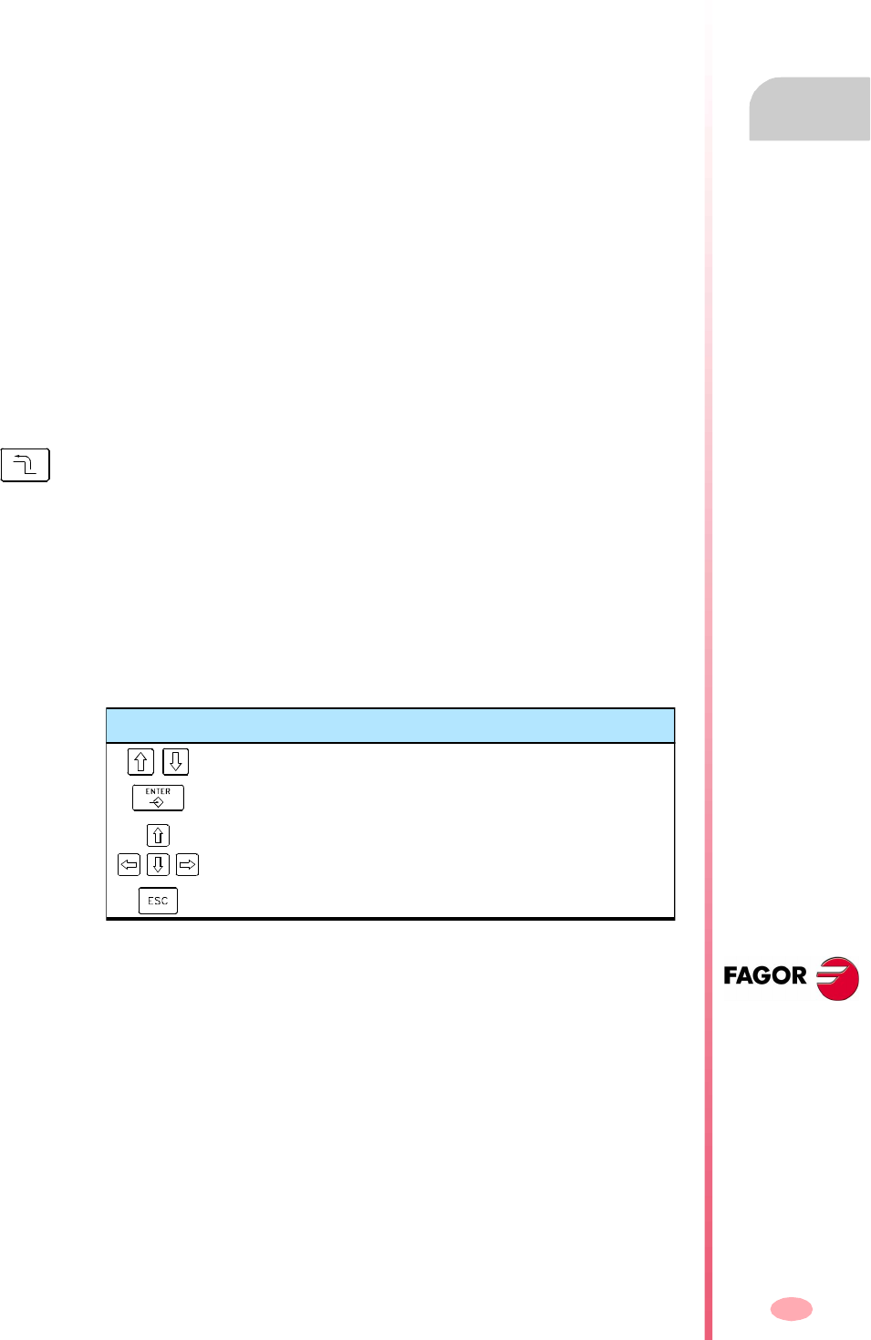
Operating manual
CNC 8070
EDITING-SIMULATION MODE
Graphic window (softkeys)
6.
(SOFT V03.0X)
123
6.5.7 Colors
It is used to change the colors used in the graphic representation.
Path colors
When a line graphics is active, it will set:
The color to draw the rapid traverse.
The color to draw the canned cycles.
The color to draw the compensated path.
The color to draw the theoretical path.
The color to draw the threading.
The background color of the window.
Colors for solids
When solid graphics is active, it will set:
The color to draw the outside X.
The color to draw the inside X.
The color to draw the outside Y.
The color to draw the inside Y.
The color to draw the outside Z.
The color to draw the inside Z.
The background color of the window.
Colors "Apply"
It assumes the new colors and applies them to the blocks drawn next. If the new colors
are not applied, the graphics are drawn with the old colors.
Colors "Edit"
It is used to select the new colors for the graphics. They are selected in the dialog
area of the graphic window that show the current colors.
When selecting this option, the softkey menu shows the available options. To return
to the main menu, press the key for the previous menu.
Keys for defining colors
To move the cursor through the data.
To open and close the color palettes.
To move the cursor through the colors of the palette.
To cancel the selected colors.
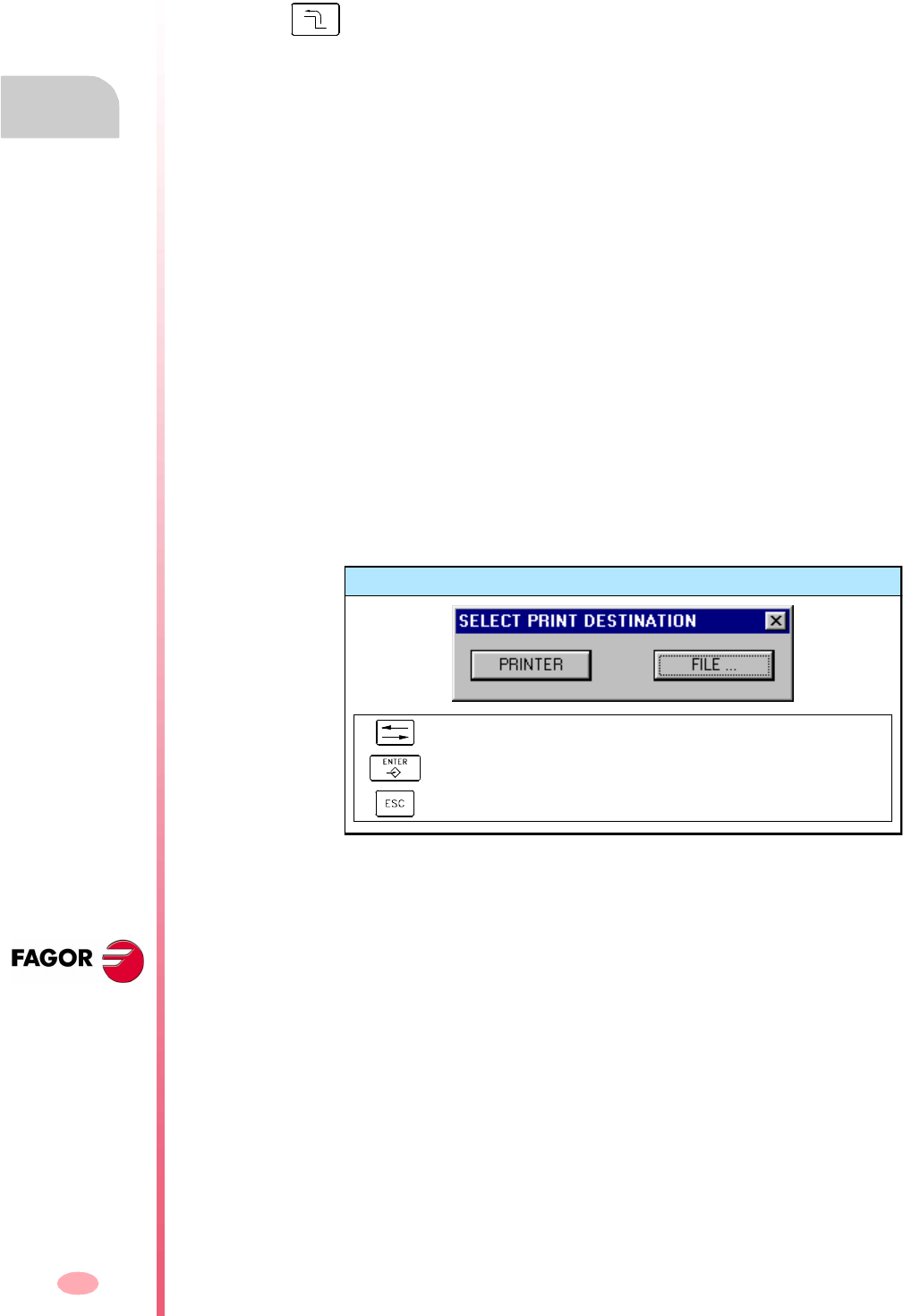
Operating manual
CNC 8070
6.
EDITING-SIMULATION MODE
Graphic window (softkeys)
(SOFT V03.0X)
124
6.5.8 Options
It is used to set the appearance and some functions of the graphic window. These
options may be used at any time, even while simulating a program.
Option "Activate" / "Deactivate"
It is used to activate or deactivate the graphic representation.
When the graphic representation is deactivated and activated, the current graphic is
erased; but the display conditions are kept active (type of graphics, zoom, graphic
parameters and display area) that were active before that mode was deactivated.
Option "Simple" / "Combined"
It is used to hide or show the dialog and data areas on the right-hand side of the
graphic window so the drawing occupies the whole graphic window.
Option "Hide Tool" / "Show Tool"
It is used to hide or show the tool while simulating in "3D solid" graphics.
Option "Print"
It is used to print the graphics in a printer connected to the CNC or as a file (BMP
format) at the CNC. When printing to a file, it is saved in the folder:
"C:\Cnc8070\Users\Reports\*.bmp"
When selecting this option, the CNC will show a dialog box requesting the print
destination (printer or file).
After selecting the destination, press [ENTER] to print it or [ESC] to cancel it.
When selecting this option, the softkey menu shows the available options. To
return to the main menu, press the key for the previous menu.
Print destination
To select the print destination.
To print the drawing.
To cancel the printing.
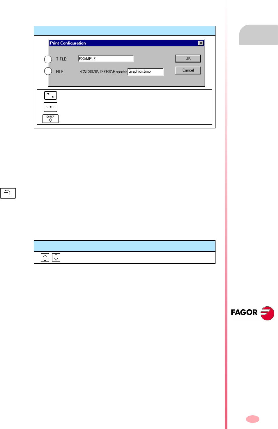
Operating manual
CNC 8070
EDITING-SIMULATION MODE
Graphic window (softkeys)
6.
(SOFT V03.0X)
125
Option "Print setup"
It is used to set the printing configuration.
When selecting this option, the CNC shows a dialog box where the following may be
defined:
A. The title of the graphics that will appear next to it in the print.
B. The name of the file where the graphics will be stored when printing out to a file.
After filling out the data, press [ENTER] to accept them or [ESC] to cancel them.
6.5.9 Speed
To change the simulation speed.
Speed "Edit"
It is used to select the new simulation speed. It is selected using the graduated ruler
that indicates the active simulation speed.
Print configuration
To move the cursor through the elements of the list.
To accept the configuration defined.
To cancel the defined configuration.
A
B
When selecting this option, the softkey menu shows the options to set the simulation
speed. To return to the main menu, press the key for the previous menu.
Keys for defining the measurement
To move the ruler cursor.
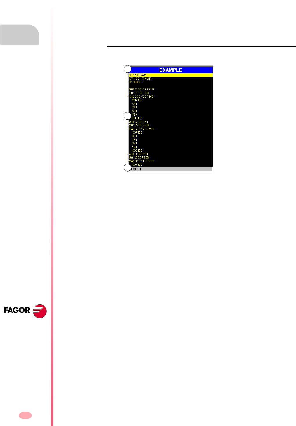
Operating manual
CNC 8070
6.
EDITING-SIMULATION MODE
Program window
(SOFT V03.0X)
126
6.6 Program window
It shows the contents of the program selected for simulation and allows selecting the
first and last blocks of the simulation. When not selected, the simulation will begin
at the first block of the block and will end after executing one of the end-of-program
functions "M02" or "M30".
While simulating, the window cursor will show the block being simulated.
Description of the program window
The program window shows the following information:
A. Title bar.
Name of the program selected for simulation.
B. Program blocks.
Contents of the program selected for simulation. While simulating, the cursor will
indicate the block being simulated.
C. Program line.
Line of the program where the cursor is.
A
B
C

Operating manual
CNC 8070
EDITING-SIMULATION MODE
Program window
6.
(SOFT V03.0X)
127
Softkey menus of the program window
When selecting the program window, the horizontal softkey menu will show the
options related to this window.
The options available in the softkey menu are the following. See "6.7 Program
window (softkeys)" on page 128.
"First block"
To set the first block of the simulation.
"Stop condition"
To select the block where the simulation of the program or subroutine will be
interrupted.
"Find text"
To find text in a program.
"Go to line"
To position the cursor on a particular line of the program.

Operating manual
CNC 8070
6.
EDITING-SIMULATION MODE
Program window (softkeys)
(SOFT V03.0X)
128
6.7 Program window (softkeys)
6.7.1 First block
It sets as the first simulation block, the block where the cursor is. When not setting
the first block, the simulation will begin at the first block of the program.
The last block may be selected using the cursor or the "Find text" or "Go to line" options
of the softkey menu.
The first block defined, remains active until canceled (with [ESC]) or until the program
is simulated; in that case, the first block of the program will become the first block of
the simulation.
Keys to move the cursor
Moves the cursor line by line.
To move the cursor page by page.
Moves the cursor to the first block or to the end of the program.
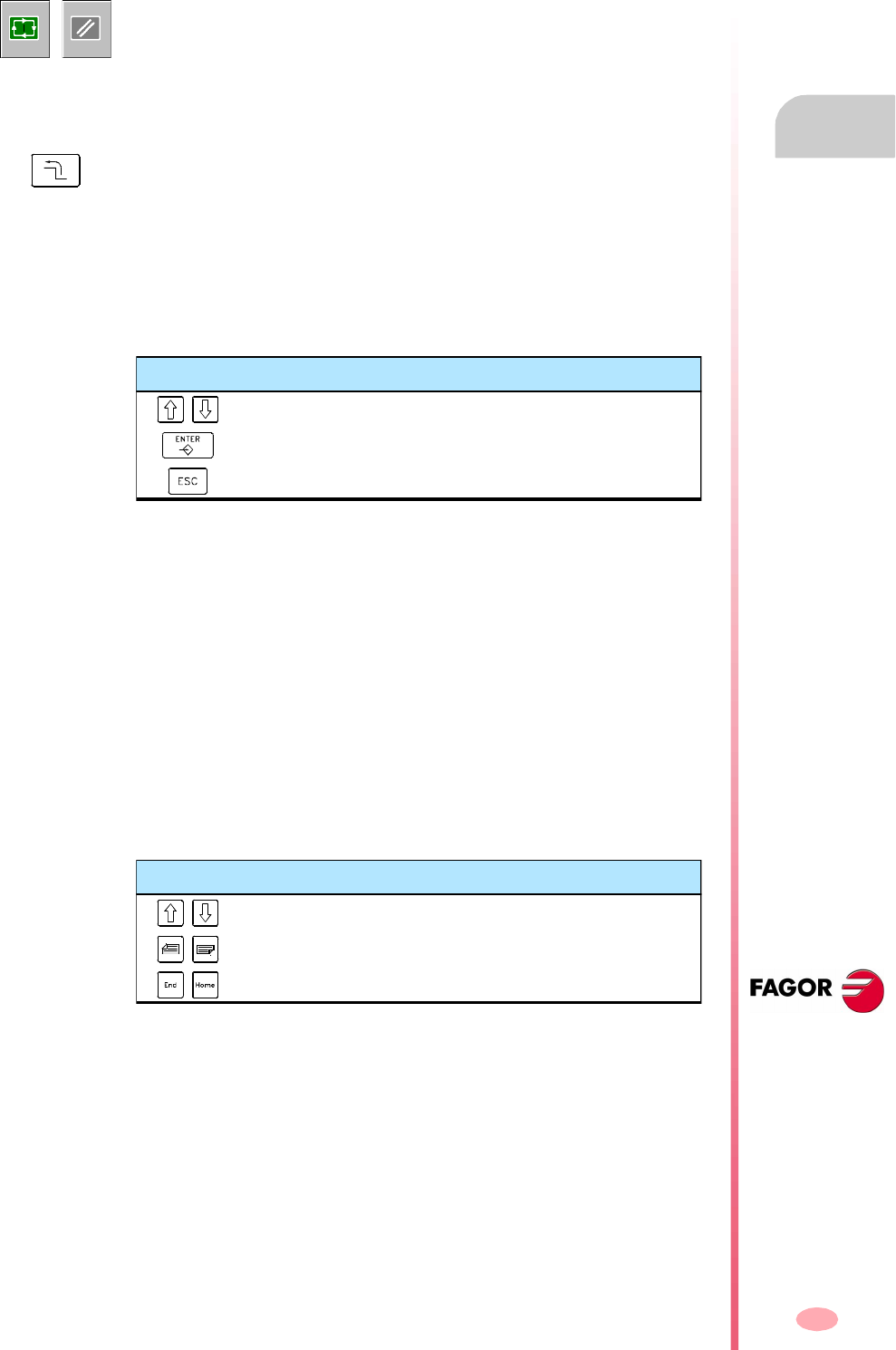
Operating manual
CNC 8070
EDITING-SIMULATION MODE
Program window (softkeys)
6.
(SOFT V03.0X)
129
6.7.2 Stop condition
If no last block is established, the simulation of the program will end after executing
one of the end-of-program functions "M02" or "M30".
Subroutine selection
To select the stop condition in a global subroutine which has been called upon from
the program. When selecting this option, the CNC shows a list of programs available
for selecting the desired subroutine.
To select a subroutine from the list.
1. Select from the list the program containing the subroutine or write its name in the
bottom window.
2. Press [ENTER] to open the program or [ESC] to cancel the selection and close
the program listing.
The program window will show the contents of the selected subroutine.
Last block
It sets the cursor position as the block where simulation is interrupted. If no last block
is established, the simulation of the program will end after executing one of the end-
of-program functions "M02" or "M30".
The last block may be selected using the cursor or the "Find text" or "Go to line" options
of the softkey menu.
The established last block remains active until it is canceled (with [ESC]) or a program
is simulated; in that case, the execution of one of the functions "M02" or "M30" is set
as the stop condition.
It is used to establish, in the program or in a subroutine, the block where the program
simulation will be interrupted. After executing that block, the simulation may be
resumed with the [START] icon or canceled with the [RESET] icon.
START RESET
When selecting this option, the softkey menu of the CNC shows the options available
for selecting the stop condition. To return to the main menu, press the key for the
previous menu.
Keys for selecting a program
To move the cursor thru the elements of the window.
To open the selected subroutine.
To cancel the selection and close the program listing.
Keys to move the cursor
Moves the cursor line by line.
To move the cursor page by page.
Moves the cursor to the first block or to the end of the program.

Operating manual
CNC 8070
6.
EDITING-SIMULATION MODE
Program window (softkeys)
(SOFT V03.0X)
130
Number of times
It sets as stop condition, that the block selected as the last block has been executed
a specific number of times.
When selecting this option, the CNC requests the number of times the block must
be executed before finishing. After entering the number of times, press [ENTER] to
validate the value or [ESC] to cancel it.
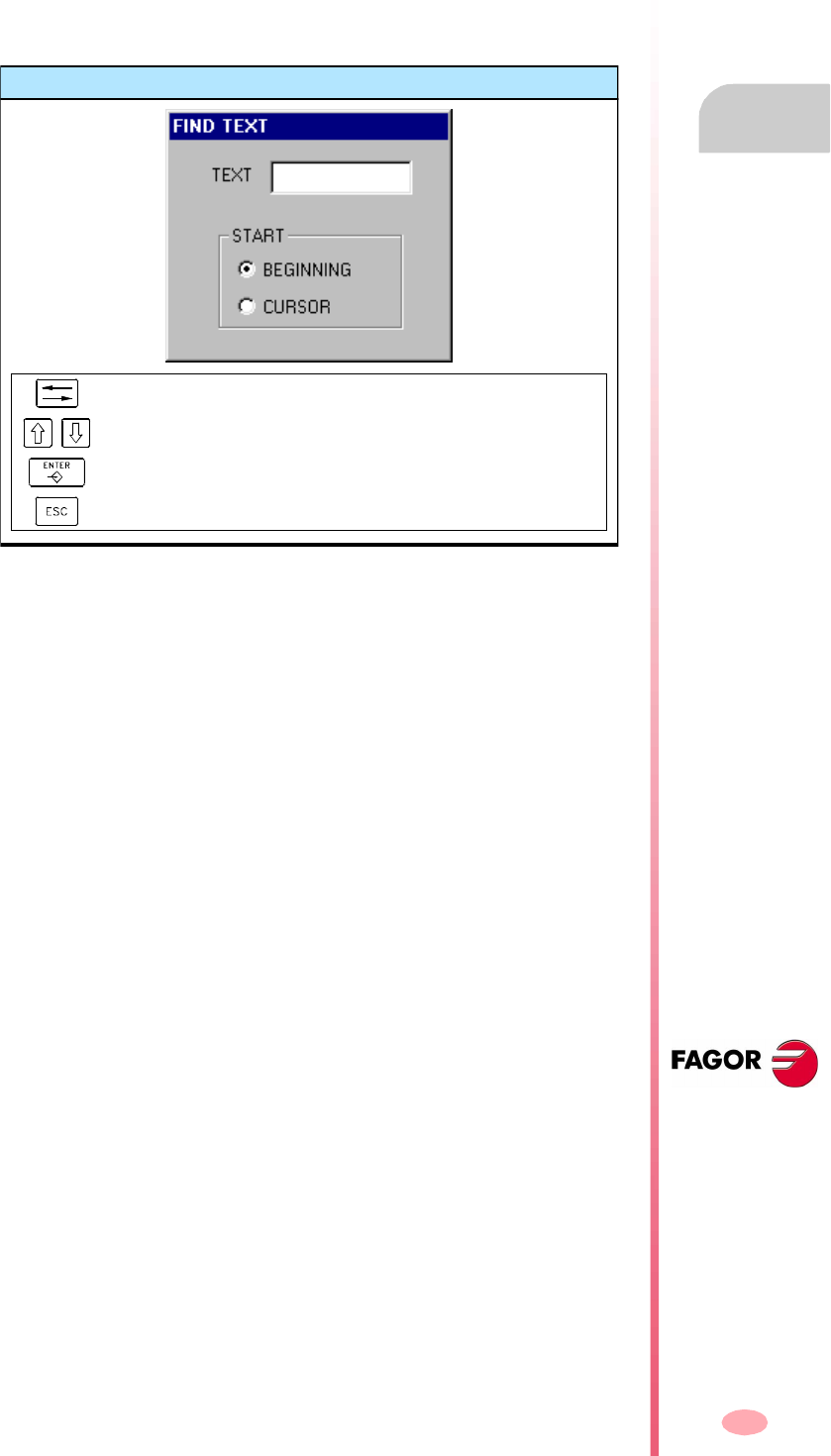
Operating manual
CNC 8070
EDITING-SIMULATION MODE
Program window (softkeys)
6.
(SOFT V03.0X)
131
6.7.3 Find text
To find text or a character string throughout the program.
When selecting this option, the CNC shows a dialog box requesting the text to be
found. It is also possible to select whether the search must start at the beginning of
the program or at cursor position.
To start the search, press [ENTER] and the cursor will position on the text found. By
pressing [ENTER] again, the CNC will look for the next match and so on.
To end the search, press [ESC]. The cursor will position on the block containing the
text searched.
6.7.4 Go to line
To position the cursor on a particular line of the program.
When selecting this option, the CNC requests the line number to go to. Key in the
desired number and press [ENTER], the cursor will then go to that line.
Find text
To move the cursor through the elements of the list.
It selects an option from a group.
To start the search.
To cancel the search and close the dialog box.
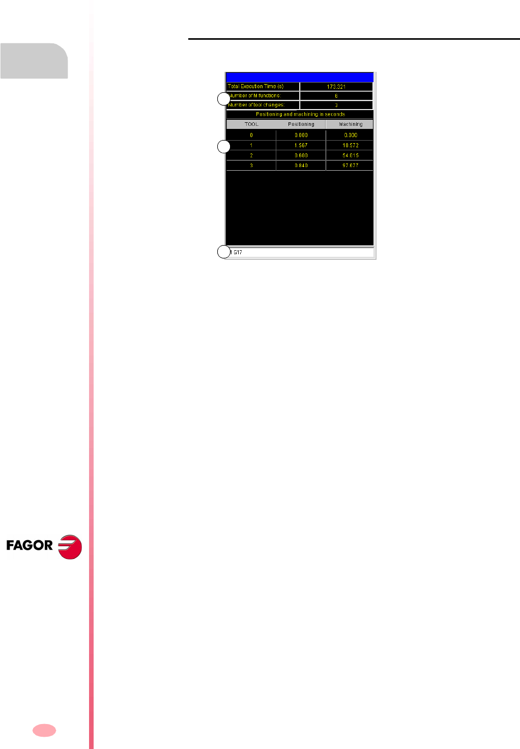
Operating manual
CNC 8070
6.
EDITING-SIMULATION MODE
Statistics window
(SOFT V03.0X)
132
6.8 Statistics window
It shows an estimate of the total execution time of the program and of the machining
time for each tool.
Description of the statistics window
This statistics window shows the following information:
A. General information.
It shows a time estimate of program execution at 100% of the programmed
feedrate, the number of "M" functions executed and the number of tool changes
made.
B. Machining time for each tool.
It shows a list of the tools used in the program indicating the machining time for
each tool and the total positioning time.
C. "G" functions active during simulation.
A
B
C
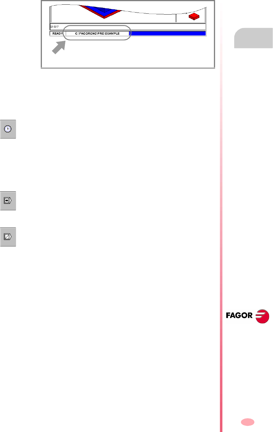
Operating manual
CNC 8070
EDITING-SIMULATION MODE
Statistics window
6.
(SOFT V03.0X)
133
6.8.1 Time estimates
The statistics window shows an estimate of the execution of the program selected
in the editing window, and whose name appears at the bottom center of the screen.
The process to estimate time is the following:
1. Use the program window to select the first and last block for the execution time
estimate.
If not selected, the execution time estimate will be done from the first block of the
program to the execution of one of the end-of-program functions "M02" or "M30".
Simulation options
These options may also be turned on or off while simulating the program. When they
are active, its corresponding icon of the icon menu will appear pressed.
The simulation options available are:
Program selected for time estimate.
2. Activate the desired simulation options using the icon menu.
3. Start the estimate calculation by pressing its TIMES icon.
"Single block" mode
It selects the "single block" mode so the execution time calculation is interrupted at
the end of each block.
Block jump
It simulates the external "block skip" switch.
When active, the CNC will NOT calculate the execution time of the blocks containing
the block-skip character "/".
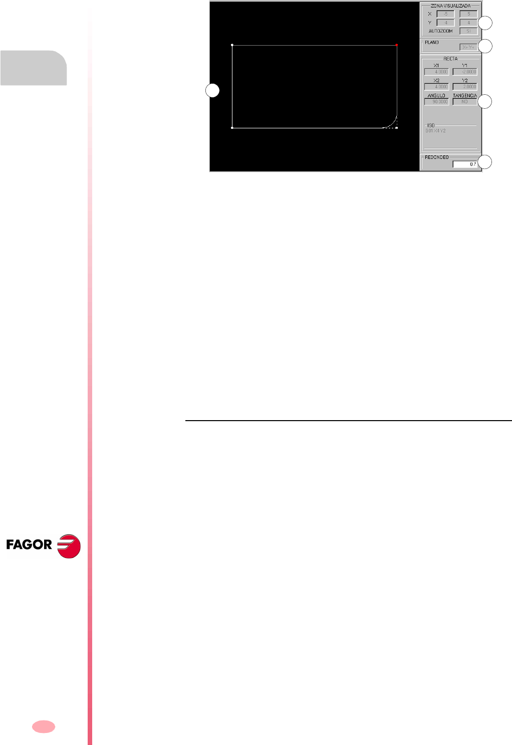
Operating manual
CNC 8070
6.
EDITING-SIMULATION MODE
Profile editor
(SOFT V03.0X)
134
6.9 Profile editor
The profile editor looks like this.
A. Graphic area
Graphic representation of the profile being drawn.
B. Displayed area.
It indicates the size of the graphic area. It is given by the maximum and minimum
coordinates of each axis.
It also shows the status of the "Autozoom" option.
C. Work plane.
It shows which are the axes that make up the work plane at the profile editor and
the direction of each one of them. The lower left corner of the graphics window
is taken as the origin of the coordinate system.
D. Data entry and display area.
Area used to enter and display the data of the elements that make up the profiles.
E. It is used to enter the values of the corners or the ISO coded text to be added to
the element.
Softkey menu
The options that may be selected from the softkey menu make it possible to edit
profiles, modify edited profiles, select the zoom, the work plane, undo the last change
and end the editing session.
While editing or modifying the profile, the softkey menu offers the option to undo the
last operation. Likewise, it offers the option to save the profile at any time.
B
A
C
D
E

Operating manual
CNC 8070
EDITING-SIMULATION MODE
Profile editor
6.
(SOFT V03.0X)
135
When accessing the profile editor, the softkey menu shows the following options:
Edit
To select the type of profile to be edited. Also too enlarge a profile, import a profile
saved in DXF format.
Modify
To modify, insert or delete elements of a profile.
Displayed area
To modify the zoom of the graphics area.
Plane
To select the axes of the plane and their direction.
End
It ends the profile editing session. Before exiting the profile editor, it will offer the
option to save or not the edited profile.
Undo
To "undo" the last operation made.
Save and continue
To save the profile and continue editing. Using this key does not require that the
profile be completed.
If the profile has been resolved, the CNC will insert it in the part program that is being
edited. If the profile cannot be resolved due to lack of data, the CNC will issue the
relevant message.

Operating manual
CNC 8070
6.
EDITING-SIMULATION MODE
Profile editor
(SOFT V03.0X)
136
6.9.1 Operating procedure
Several profiles may be edited without having to exit the profile editor. To edit a profile,
proceed as follows:
1. Select the type of profile to be edited, such as a circular or rectangular profile or
any profile.
2. For a rectangular or circular profile, define its data and insert it. For any profile,
first select the starting point of the profile.
Once the first point has been selected, draw the profile, which will be made up
of straight and curved sections. If it has corner rounding, chamfering or tangential
entries and exits, use one of these methods:
•Treat them as individual sections when having enough information to define
them.
•Ignore them while defining the profile and, once it has been defined, select
the corners that have those characteristics and insert them.
3. End the profile editing session by inserting them into the program.
The portion of ISO-code program corresponding to the edited profile will be
identified with the line "(#PROFILE)" or it will appear framed between the lines
"(#PROFILE BEGIN)" and "(#PROFILE END)".
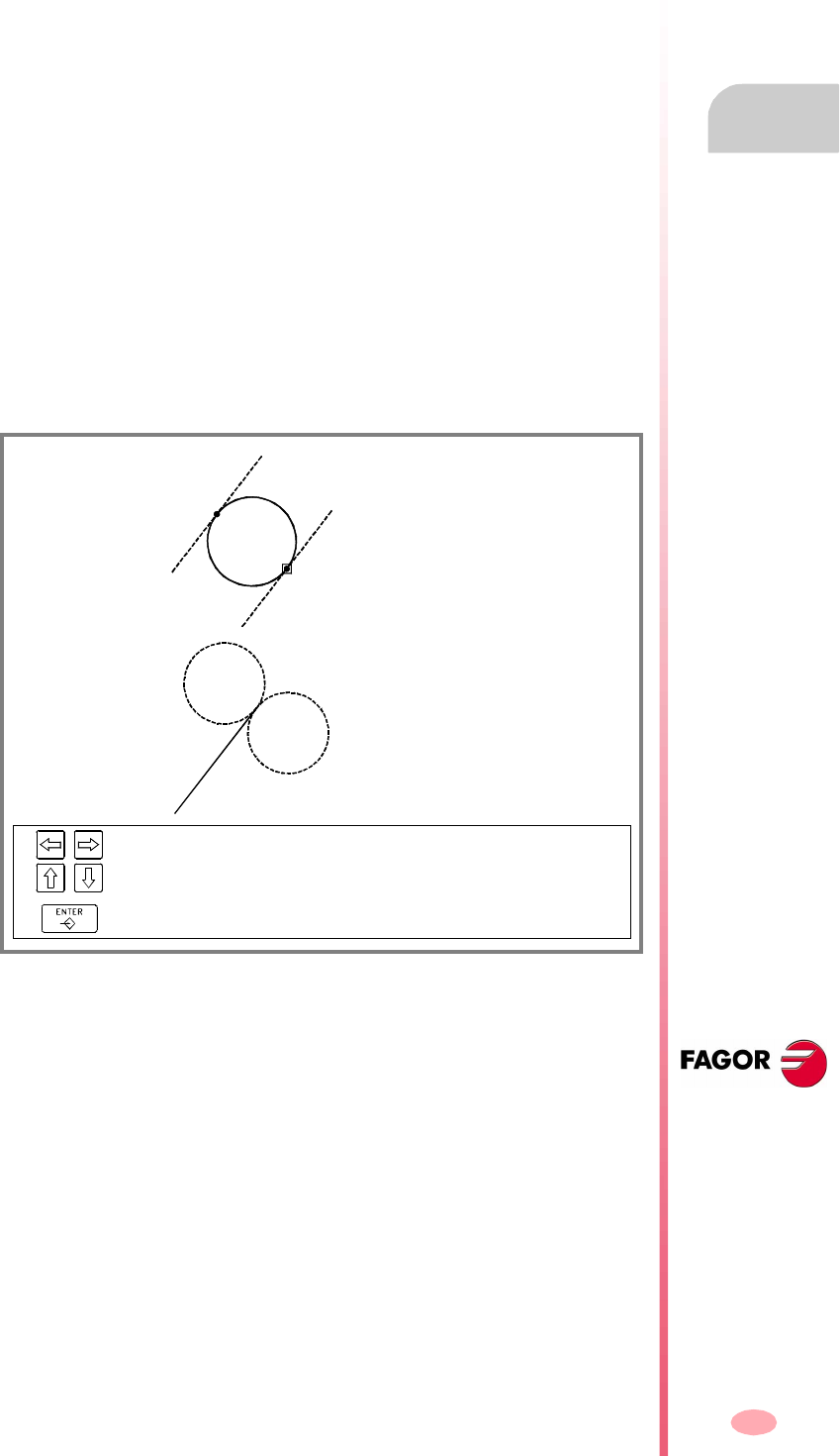
Operating manual
CNC 8070
EDITING-SIMULATION MODE
Profile editor
6.
(SOFT V03.0X)
137
6.9.2 Data editing
All data need not be defined; but it is recommended to define all the known data. To
define the profile data, proceed as follows:
1. Press the softkey corresponding to the data to be defined.
2. Key in the desired value (which may be a numeric constant or an expression). Use
the [SPACE] key to change the value of a non-numerical data (tangency, direction,
etc.).
3. Press [ENTER] to accept the defined value or [ESC] to reject it and return to the
previous one. If the entered value is accepted, the CNC will select the next data.
Once all the data has been defined, press the "Validate" softkey and the CNC will
show the profile that has been defined.
Displaying incomplete sections
If there isn't enough data to show the defined section, the CNC will draw as much
of it as it knows. The sections that are not fully defined will be shown with a dash line.
If there are more than one possibility, it will show the available options one by one
except the ones that could generate tangency errors later on; select the desired
option. The sections with several possibilities will be shown in green whereas the rest
of the sections will be shown in white.
X1 = ?
Y1 = ?
X2 = ?
Y2 = ?
Angle = 60º
Tangent = Yes
X1 = 40 Y1 = 30
X2 = ? Y2 = ?
Xc = ? Yc = ?
Radius = 20
Tangent = Yes
To select the available options.
To assume the selected option.

Operating manual
CNC 8070
6.
EDITING-SIMULATION MODE
Profile editor
(SOFT V03.0X)
138
6.9.3 Profile definition
With the softkey menu of this screen, it is possible to define any profile, a circular or
a rectangular one or to configure the graphics screen.
When accessing the editing menu, the softkey menu shows the following options:
Profile
To edit any profile by defining the straight and curved sections that make it up.
See "6.9.6 Defining any profile" on page 141.
Circle
For quickly defining a circular profile. See "6.9.4 Circular profile definition" on
page 139.
Rectangle
For quickly defining a rectangular profile. See "6.9.5 Rectangular profile
definition" on page 140.
Expanding a profile
For adding a straight line or an arc in any position of a previously edited profile.
Import profile
For importing a previously saved profile.
These profiles may also be imported in DXF format besides in ISO format.
Undo
To "undo" the last operation made.
Save and continue
To save the profile and continue editing. Using this key does not require that the
profile be completed.
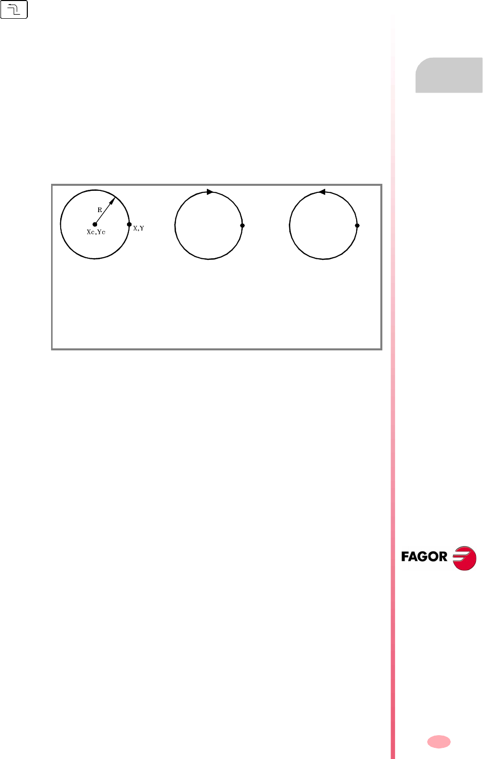
Operating manual
CNC 8070
EDITING-SIMULATION MODE
Profile editor
6.
(SOFT V03.0X)
139
6.9.4 Circular profile definition
X Y To define the coordinates of the profile's starting point.
Xcenter To define the profile's center coordinate along the abscissa axis.
Ycenter To define the profile's center coordinate along the ordinate axis.
Radius To define the profile radius.
Direction To define the direction of the profile (clockwise or counterclockwise).
Validate To accept and draw the defined profile.
The data is defined in the data area of the screen where the following information is
shown:
X1, Y1 Coordinates of the profile's starting point.
XC Profile's center coordinate along the abscissa axis.
YC Profile's center coordinate along the ordinate axis.
RADIUS Radius of the arc.
DIRECTION It indicates the direction of the profile.
The softkey menu shows the necessary options for defining a circular profile. To return
to the main menu, press the key for the previous menu.
Clockwise arc Counterclockwise arc
X Y Coordinates of the profile's starting point.
Xc, Yc Profile’s center coordinates.
RRadius of the profile.
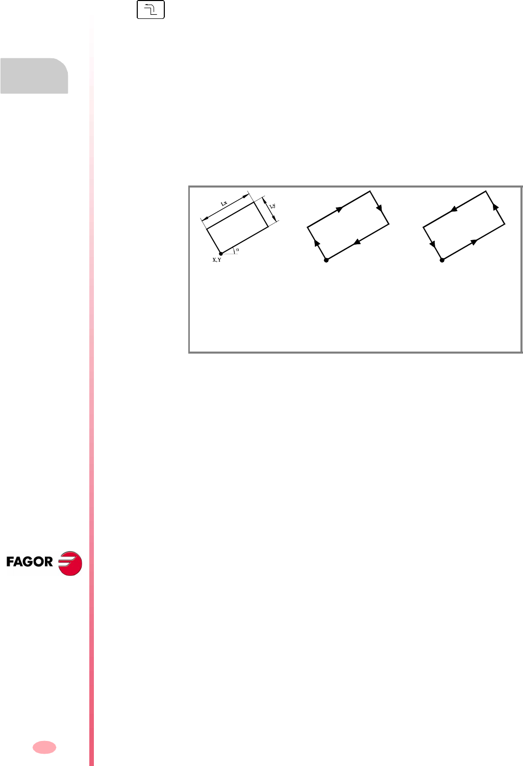
Operating manual
CNC 8070
6.
EDITING-SIMULATION MODE
Profile editor
(SOFT V03.0X)
140
6.9.5 Rectangular profile definition
X Y To define the coordinates of the profile's starting point.
Length X To define the profile's length along the abscissa axis.
Length Y To define the profile's length along the ordinate axis.
Angle To define the angle of the profile referred to the abscissa axis.
Direction To define the direction of the profile (clockwise or counterclockwise).
Validate To accept and draw the defined profile.
The data is defined in the data area of the screen where the following information is
shown:
X1, Y1 Coordinates of the profile's starting point.
XL Profile's length along the abscissa axis.
YL Profile's length along the ordinate axis.
ANGLE Angle of the profile with the abscissa axis.
DIRECTION It indicates the direction of the profile.
The softkey menu shows the necessary options for defining a rectangular profile. To
return to the main menu, press the key for the previous menu.
Clockwise arc Counterclockwise arc
X Y Coordinates of the profile's starting point.
Lx, Ly Length of the profile along both axis.
το Angle of the profile with the abscissa axis.

Operating manual
CNC 8070
EDITING-SIMULATION MODE
Profile editor
6.
(SOFT V03.0X)
141
6.9.6 Defining any profile
To define a new profile, the CNC request the starting point of the profile. Define it with
the relevant softkeys and press the "Validate" softkey. The graphic area will show the
profile's starting point.
Straight
To edit a straight section.
Clockwise arc
To edit a clockwise arc.
Counterclockwise arc
To edit a counterclockwise arc.
New profile
To edit a new profile.
Modify the last one
For modifying the last section of the profile.
Definition of a straight section
To define a straight section, the softkey menu shows the necessary options to define
the data for the section.
X Y To define the section's end point.
Angle To define the angle of the straight section with the abscissa axis.
Tangency To define whether the section is tangent to the previous path.
Validate To accept and draw the defined section.
The data is defined in the data area of the screen where the following information is
shown:
X1, Y1 Coordinates of the section's starting point. They cannot be modified because they
belong to the endpoint of the previous section.
X2, Y2 Coordinates of the section's endpoint.
ANGLE Angle of the straight section with the abscissa axis.
TANGENCY It indicates whether or not the section is tangent to the previous path.
Once the profile's starting point has been defined, the softkey menu will show the
necessary options to define the profile. To return to the main menu, press the key for
the previous menu.

Operating manual
CNC 8070
6.
EDITING-SIMULATION MODE
Profile editor
(SOFT V03.0X)
142
Definition of a curved section (clockwise or counterclockwise)
To define a curved section, the softkey menu shows the necessary options to define
the data for the section.
X Y To define the section's end point.
Center X To define the arc's center coordinate along the abscissa axis.
Center Y To define the arc's center coordinate along the ordinate axis.
Radius To define the arc radius.
Tangency To define whether the section is tangent to the previous path.
Validate To accept and draw the defined section.
The data is defined in the data area of the screen where the following information is
shown:
X1, Y1 Coordinates of the section's starting point. They cannot be modified because they
belong to the endpoint of the previous section.
X2, Y2 Coordinates of the section's endpoint.
Xc Coordinates of the section's center along the abscissa axis.
Yc Coordinates of the section's center along the ordinate axis.
RADIUS Radius of the arc.
TANGENCY It indicates whether or not the section is tangent to the previous path.

Operating manual
CNC 8070
EDITING-SIMULATION MODE
Profile editor
6.
(SOFT V03.0X)
143
6.9.7 Modify a profile and insert corners
To modify the defined profiles by either modifying or deleting the existing elements
or inserting new elements. Likewise, it is possible to insert rounding, chamfers and
tangential entries or exits.
When selecting this option, the softkey menu will show the necessary options to
modify the profile.
Modify element
It is possible to modify any data of a section of the profile.
Once the desired element has been selected, one may modify the type of section
(straight or arc) or its data. Once the element has been modified, press "Validate"
to confirm the changes.
The CNC recalculates the new profile according to the data used to define that
section and the next one (tangency, angle, etc.)
Insert element
To insert a new element in any position of the profile.
After selecting the section after which the element is to be inserted, select the type
of section (straight or arc) to be inserted, define its parameters and press the
"Validate" softkey.
The CNC recalculates the new profile according to the data used to define that
section and the next one (tangency, angle, etc.)
Delete element
To delete an element of the selected profile.
Once the element to be deleted has been selected, confirm the command by
pressing [ENTER].
The CNC recalculates the new profile.
Corners
To include rounding, chamfers, tangential entries or exits in the defined profile.
See "Corner definition" on page 144.
Additional ISO
For adding an ISO coded line to a previously closed profile.
Once the ISO coded line to be added has been entered, confirm the command
by pressing the [ENTER] key.
Operating manual
CNC 8070
6.
EDITING-SIMULATION MODE
Profile editor
(SOFT V03.0X)
144
Corner definition
To include rounding, chamfers, tangential entries or exits in the defined profile.
When selecting this option, the softkey menu shows the type of corners that can be
inserted.
Rounding
To insert a rounding at the profiles corners where it is possible.
Chamfer
To insert a chamfer at the profiles corners where it is possible.
Tangential entry
To add a tangential tool entry at the beginning of the profile.
Tangential exit
To add a tangential tool exit at the end of the profile.
Once the type of corner to be inserted has been selected, the CNC will highlight in
red one of the corners of the profile.
Select the profile corner to be modified and the CNC will request the value (radius
or size) of the corner to be inserted:
•For a rounding, enter the rounding radius.
•For a chamfer, enter the size of the chamfer.
•For a tangential entry, enter the entry radius.
•For a tangential exit, enter the exit radius.
After defining the value of the corner, press [ENTER] to insert the corner in the profile.
Then, one may select another corner or quit this mode by pressing [ESC].
Keys to select a corner
To select a corner of the profile.
To select a corner of another profile.

Operating manual
CNC 8070
EDITING-SIMULATION MODE
Profile editor
6.
(SOFT V03.0X)
145
6.9.8 Display area
The softkey menu of this screen may be used to modify the zoom of the graphics area.
When accessing the "display area" menu, the softkey menu shows the following
options:
Zoom +, zoom -
To enlarge or reduce the display area.
Use the arrow keys to move the drawings of the profiles. Use the "+" and "-" keys
of the keyboard to enlarge or reduce the drawings of the profiles.
Optimum area
It selects the best display area, i.e. it places the profile in the center of the graphics
area and selects the best zoom possible to show the whole profile.
Autozoom
When applying Autozoom, every time a new section is inserted which goes
beyond the screen, the profile will automatically be centered and zoomed in or
out to show the whole profile. This way, it will show the whole profile again.
Validate
It may be used to confirm the changes made.

Operating manual
CNC 8070
6.
EDITING-SIMULATION MODE
Profile editor
(SOFT V03.0X)
146
6.9.9 Work plane definition
The softkey menu of this screen may be used to modify the axes of the plane and
their directions.
When accessing the plane menu, the softkey menu shows the following options:
Abscissa axis
For selecting the abscissa axis among X, Y and Z.
Abscissa direction
For selecting the direction of the abscissa axis between + and -.
Ordinate axis
For selecting the ordinate axis among X, Y and Z.
Ordinate direction
For selecting the direction of the ordinate axis between + and -.
Validate
It may be used to confirm the changes made.

Operating manual
CNC 8070
EDITING-SIMULATION MODE
Profile editor
6.
(SOFT V03.0X)
147
6.9.10 End
It ends the profile editing session. When selecting this option, the softkey menu shows
the following options.
Save profile
It inserts the profile in the program and exits the profile editor.
Do not save profile
It does not insert the profile in the program and it exits the profile editor.
Continue
It does not insert the profile in the program and it goes on editing profile.
If the profile has been resolved, the CNC will insert it in the part program that is being
edited. If the profile cannot be resolved due to lack of data, the CNC will issue the
relevant message.

Operating manual
CNC 8070
6.
EDITING-SIMULATION MODE
Profile editor
(SOFT V03.0X)
148
6.9.11 Profile editor. Example 1
Profile definition without rounding, chamfers or tangential entries and exits.
Definition of rounding, chamfers and tangential entries and exits
Select the "CORNERS" option and define:
Press [ESC] to quit the "CORNER" option.
End of editing
Select the "END" option and save the profile. The CNC quits the profile editor and
inserts the profile in the part-program.
Starting point X = 80 Y =-20
Straight X = 80 Y =20
Straight X = 20 Y =20
Straight X = 20 Y =80
Straight X = 60 Y =80
Counterclockwise arc X = 100 Y =80 Center X = 80 Center Y = 80 Radius = 20
Straight X = 140 Y =80
Straight X = 140 Y =20
Straight X = 80 Y =20
Straight X = 80 Y =-20
Tangential entry Select point "1" Assign radius = 5 Press [ENTER]
Chamfer Select point "2" Assign size = 10 Press [ENTER]
Rounding Select point "3" Assign radius = 10 Press [ENTER]
Rounding Select point "4" Assign radius = 5 Press [ENTER]
Rounding Select point "5" Assign radius = 5 Press [ENTER]
Rounding Select point "6" Assign radius = 10 Press [ENTER]
Chamfer Select point "7" Assign size = 10 Press [ENTER]
Tangential exit Select point "1" Assign radius = 5 Press [ENTER]
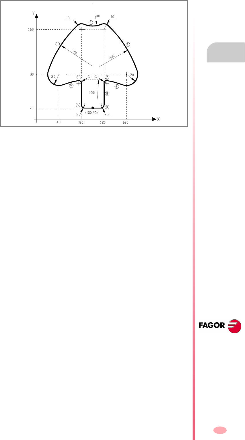
Operating manual
CNC 8070
EDITING-SIMULATION MODE
Profile editor
6.
(SOFT V03.0X)
149
6.9.12 Profile editor. Example 2
Definition of a profile without rounding.
Rounding definition "A" and "B".
Select the "CORNERS" option and define:
Press [ESC] to quit the "CORNER" option.
End of editing
Select the "END" option and save the profile. The CNC quits the profile editor and
inserts the profile in the part-program.
Starting point X = 100 Y =20
Straight X = 80 Y =20
Straight X = 80 Angle = 90
Counterclockwise
arc
(1) Center X = 75 Radius = 5 Tangency = Yes
Counterclockwise
arc
(2) Center X = 100 Radius = 150 Tangency = Yes
Clockwise arc Center X = 40 Center Y = 80 Radius = 20 Tangency = Yes
The CNC shows the options for section 2. Select the correct one.
The CNC shows the options for section 1. Select the correct one.
Clockwise arc (3) Radius = 200 Tangency = Yes
Clockwise arc Center X = 80 Center Y = 160 Radius = 10 Tangency = Yes
The CNC shows the options for section 3. Select the correct one.
Counterclockwise
arc
(4) Radius = 40 Tangency = Yes
Clockwise arc Center X = 120 Center Y = 160 Radius = 10 Tangency = Yes
The CNC shows the options for section 4. Select the correct one.
Clockwise arc (5) Radius = 200 Tangency = Yes
Clockwise arc Center X = 160 Center Y = 80 Radius = 20 Tangency = Yes
The CNC shows the options for section 5. Select the correct one.
Counterclockwise
arc
(6) Center X = 100 Radius = 150 Tangency = Yes
The CNC shows the options for section 6. Select the correct one.
Counterclockwise
arc
(7) Center X = 125 Radius = 5 Tangency = Yes
The CNC shows the options for section 7. Select the correct one.
Straight (8) X = 120 Y =20 Tangency = Yes
The CNC shows the options for section 8. Select the correct one.
Straight X = 100 Y =20
Rounding Select point "A" Assign radius = 5 Press [ENTER]
Rounding Select point "B" Assign radius = 5 Press [ENTER]
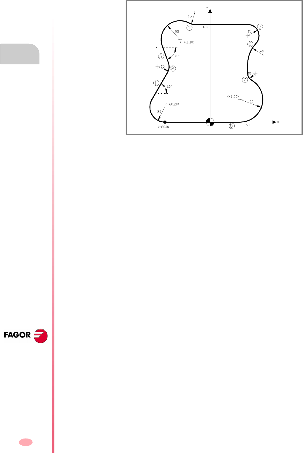
Operating manual
CNC 8070
6.
EDITING-SIMULATION MODE
Profile editor
(SOFT V03.0X)
150
6.9.13 Profile editor. Example 3
Profile definition.
End of editing
Select the "END" option and save the profile. The CNC quits the profile editor and
inserts the profile in the part-program.
Starting point X = -60 Y =0
Clockwise arc Center X = -60 Center Y = 20 Radius = 20
Straight (1) Angle = 60 Tangency = Yes
The CNC shows the options for section 1. Select the correct one.
Counterclockwise
arc
(2) Radius = 15 Tangency = Yes
Straight (3) Angle = -70 Tangency = Yes
Clockwise arc Center X = -40 Center Y = 110 Radius = 25 Tangency = Yes
The CNC shows the options for section 3. Select the correct one.
The CNC shows the options for section 2. Select the correct one.
Counterclockwise
arc
(4) Radius = 15 Tangency = Yes
Straight Y =130 Angle = 0 Tangency = Yes
The CNC shows the options for section 4. Select the correct one.
Clockwise arc (5) Center X = 50 Radius = 15 Tangency = Yes
The CNC shows the options for section 5. Select the correct one.
Counterclockwise
arc
(6) Radius = 40 Tangency = Yes
Straight X = 50 Angle = 270 Tangency = Yes
The CNC shows the options for section 6. Select the correct one.
Counterclockwise
arc
(7) Radius = 10 Tangency = Yes
Clockwise arc Center X = 40 Center Y = 30 Radius = 30 Tangency = Yes
The CNC shows the options for section 7. Select the correct one.
Straight (8) X = -60 Y =0 Tangency = Yes
The CNC shows the options for section 8. Select the correct one.
151
CNC 8070
(SOFT V03.0X)
7
MDI MODE
MDI mode selection
This work mode may be accessed from any channel. The blocks are executed in the
active channel.
The MDI mode lays over all the other work modes in such a way that when quitting
the MDI mode by pressing [ESC], the CNC goes into the work mode from where the
MDI mode was accessed.
Operations in MDI mode
The following operations are possible in this work mode:
•Edit and execute individual blocks.
•Save the set of blocks executed as an independent program.
The MDI mode may be accessed from any other operating mode, except when a
program is in execution (even it is interrupted) by pressing its relevant key.

Operating manual
CNC 8070
7.
MDI MODE
Appearance of the MDI mode
(SOFT V03.0X)
152
7.1 Appearance of the MDI mode
When this operating mode is active, it will be indicated at the top right side of the
general status bar.
This mode may be displayed with several screens. The current screen and the total
number of available screens are shown at the upper right hand side of the general
status bar.
Switching between the different screens is done by pressing the MDI mode accessing
key. The screen selection is rotary in such a way that when pressing this key on the
last screen, it shows the first one of the operating mode.
Standard configuration
The standard configuration of this work mode, described in this manual corresponds
to the one supplied by Fagor. In some cases, the manual shows a sample screen,
instead of that of the CNC in order to make it easier to understand.
These screens may be customized by the machine manufacturer changing its
contents as well as its appearance. They may also remove certain screens or add
some of their own.
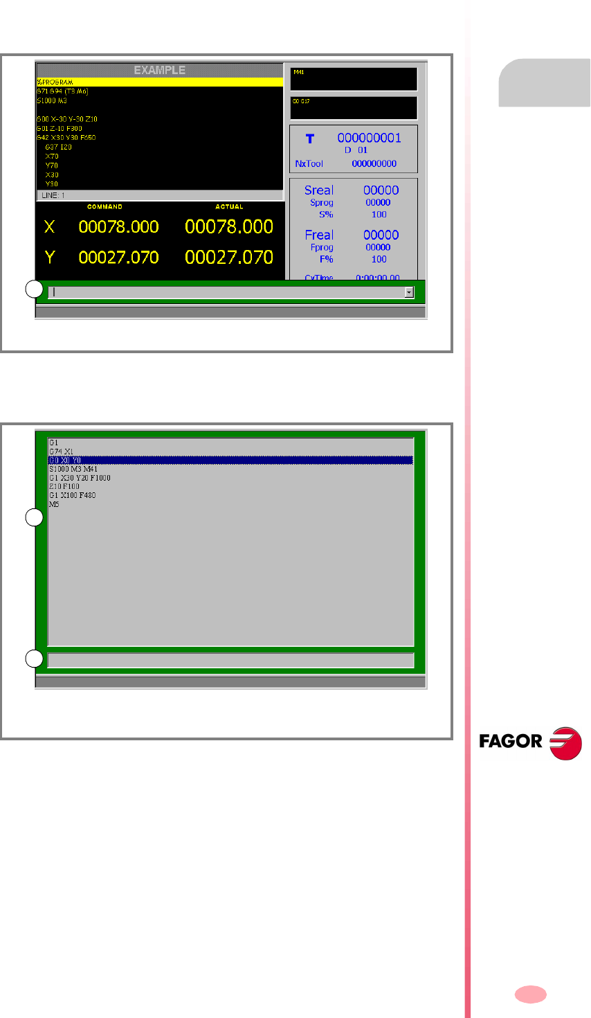
Operating manual
CNC 8070
MDI MODE
Appearance of the MDI mode
7.
(SOFT V03.0X)
153
7.1.1 Window description
As mentioned earlier, the MDI mode may be displayed with two different windows
(later sections of this chapter describe how to use them).
Standard window
The standard window only displays one edit line for editing new blocks.
Full screen
The full screen shows the blocks saved so far and an edit line for editing new blocks.
(A) Window for the MDI mode (Editing line).
(A) History of edited blocks.
(B) Edit line.
A
B
A
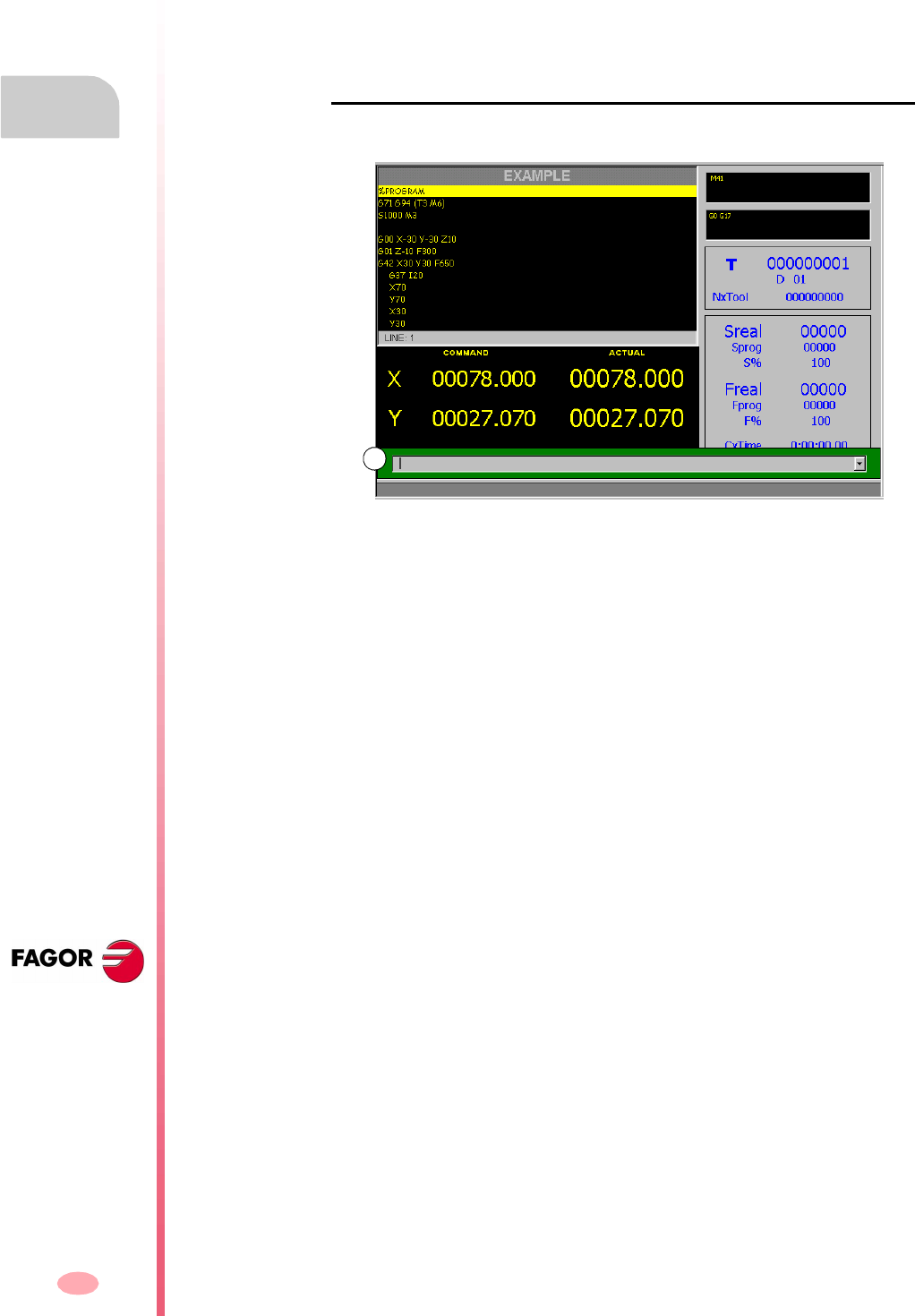
Operating manual
CNC 8070
7.
MDI MODE
Standard MDI window
(SOFT V03.0X)
154
7.2 Standard MDI window
This window only shows the edit line of the MDI mode.
It is possible to edit and execute new blocks or recover blocks saved in the block
history, which may be modified before executing them.
Description
The standard MDI mode window shows the following information:
A. Window for the MDI mode (Editing line).
Window where the blocks to be executed are edited. Blocks are edited one by one.
A
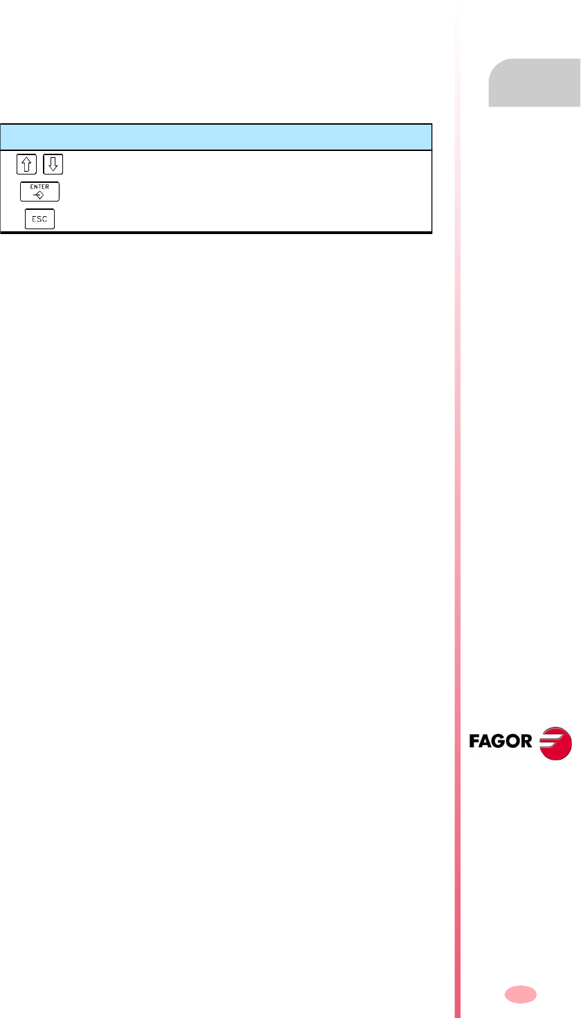
Operating manual
CNC 8070
MDI MODE
Standard MDI window
7.
(SOFT V03.0X)
155
7.2.1 Block editing and execution
In this window, it is possible to edit and execute new blocks or the ones saved in the
block history. Only the blocks previously executed will be saved in the block history.
While editing, it analyzes the syntax of the block being edited. When trying to execute,
if the block is incorrect, it shows a warning message and it does not execute it.
Block editing
The blocks may be edited directly on the edit line or may be recalled from the block
history.
The recalled blocks may be modified before executing them as if they were new ones.
Block execution
The block on the edit line is executed by pressing [START] at the operator panel. Once
the block has been executed is saved in the block history.
The [STOP] key interrupts the execution of the block. Press [START] again to resume
execution from where it was interrupted.
The [RESET] key cancels the execution of the block and resets the CNC to its initial
conditions.
Keys for selecting a block from history
To access the history and select a block.
To accept the selection and show the block on the edit line.
To cancel the selection and quit the MDI mode.
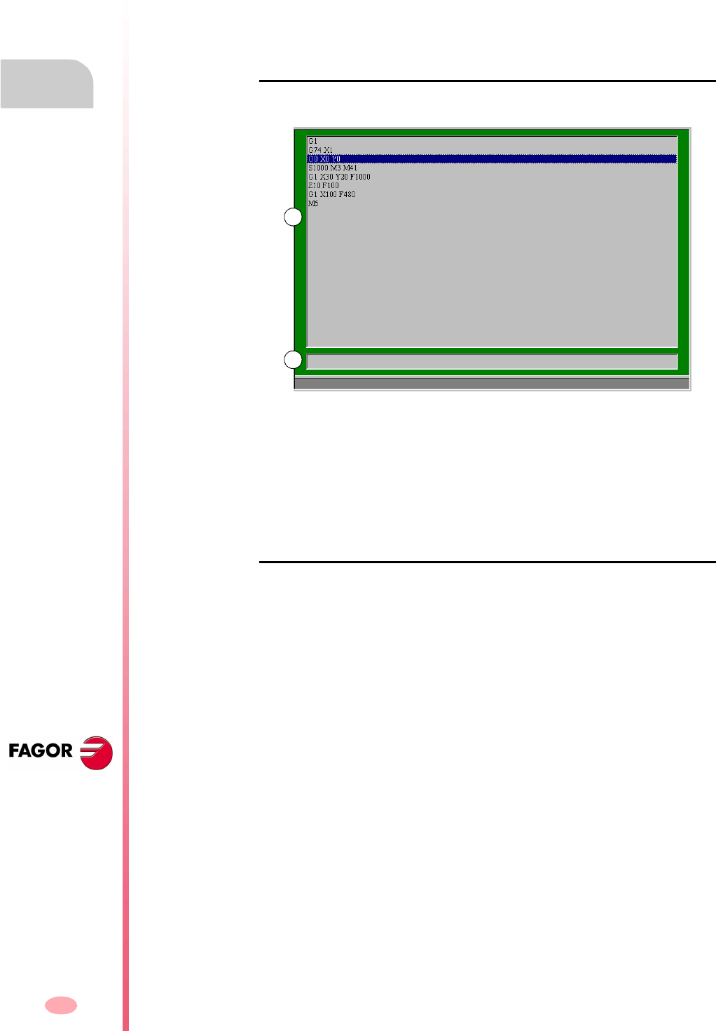
Operating manual
CNC 8070
7.
MDI MODE
Full MDI screen
(SOFT V03.0X)
156
7.3 Full MDI screen
This window shows the blocks saved so far and the edit line of the MDI mode.
It is possible to edit and execute new blocks or recover blocks saved in the block
history, which may be modified before executing them.
Description
The full MDI mode screen shows the following information:
A. History of edited blocks.
The block history shows a list of the blocks edited in MDI mode. Every time a new
block is edited, it is added to this history.
B. Edit line.
The blocks to be executed are edited on the edit line. Blocks are edited one by one.
Softkey menu
When selecting the full screen, the horizontal softkeys show the options related to
this window.
The options available in the softkeys menu are:
"New block"
It positions the cursor on the edit line.
"Modify"
Recovers the block selected by the cursor and it displays it on the edit line.
This option is the same as pressing [ENTER].
"Delete"
It deletes the block selected by the cursor.
"Cancel edit"
It cancels the editing of the block and it shows an empty edit line.
This option is only available when editing a block.
B
A

Operating manual
CNC 8070
MDI MODE
Full MDI screen
7.
(SOFT V03.0X)
157
"Delete all"
It deletes all the blocks from the block history.
"Save"
It saves all the history blocks as an independent program.
Operating manual
CNC 8070
7.
MDI MODE
Full MDI screen
(SOFT V03.0X)
158
7.3.1 Block execution
In this window, it is possible to edit and execute new blocks or the ones saved in the
block history.
Block editing
The blocks may be edited directly on the edit line or may be recalled from the block
history.
The recalled blocks may be modified before executing them as if they were new ones.
The blocks edited or modified appearing on the edit line may be executed or saved
in the block history.
Saving a block
Press [ENTER] to save a block in the history without executing it.
If it is a new block, it will be added to the history whereas if it is modified block, it will
replace the previous one in the history.
Block execution
The block on the edit line is executed by pressing [START] at the operator panel. Once
the block has been executed is saved in the block history.
The [STOP] key interrupts the execution of the block. Press [START] again to resume
execution from where it was interrupted.
The [RESET] key cancels the execution of the block and resets the CNC to its initial
conditions.
Keys for selecting a block from history
To access the history and select a block.
To accept the selection and show the block on the edit line.
To cancel the selection and quit the MDI mode.
Operating manual
CNC 8070
MDI MODE
Full MDI screen
7.
(SOFT V03.0X)
159
7.3.2 Save the blocks as a program
To save the block history as an independent program, press the "Save" softkey and
the CNC will show a list of the programs saved at the CNC.
To save the program:
1. Write the program name in the bottom window. To replace an existing program,
select it from the list.
2. Press [ENTER] to save the program or [ESC] to return to the MDI mode without
saving the program.
Keys for selecting a block from history
To switch windows.
To move the cursor thru the elements of the window.
To save the new program.
To cancel the selection and close the program listing.

Operating manual
CNC 8070
7.
MDI MODE
Full MDI screen
(SOFT V03.0X)
160

161
CNC 8070
(SOFT V03.0X)
8
USER TABLES
User table selection
The user tables consist of the following tables:
•Zero offset table.
•Clamp tables (fixtures).
•Table of arithmetic parameters, global, local and common.
In order to activate a fixture zero or part zero offset, those values must be previously
stored in the relevant CNC table.
What can you do in this work mode?
The following operations are possible in this work mode:
•Edit and modify the tables for zero offsets and parameters.
•Save the content of a table.
•Recover the content of a table.
•Print the content of a table.
•Initialize a table.
The CNC tables may be accessed from any other operating mode, even while a
program is in execution, by pressing the key for these tables.

Operating manual
CNC 8070
8.
USER TABLES
Appearance of the table mode
(SOFT V03.0X)
162
8.1 Appearance of the table mode
This operating mode consists of several tables. The various tables may be selected
using the horizontal softkeys.
Some tables are common to all the channels and others belong to each channel. In
this case, by default, they show the ones of the active channel; but it is possible to
access those of any other channel from the vertical softkey menu.
The zero offset tables and fixture offset tables are common to all the channels;
however, in each channel they show the axes of that channel. When applying an offset
in a channel, it is only applied to the axes that are part of the channel at the time.
The tables available are:
•Zero offset table.
•Fixture table.
•Table of global parameters. There is a table for each channel.
•Table of local parameters. There are seven tables for each channel, one table per
level.
•Table of common parameters. The table is common to all the channels.
Standard configuration
The standard configuration of this work mode, described in this manual corresponds
to the one supplied by Fagor. In some cases, the manual shows a sample screen,
instead of that of the CNC in order to make it easier to understand.
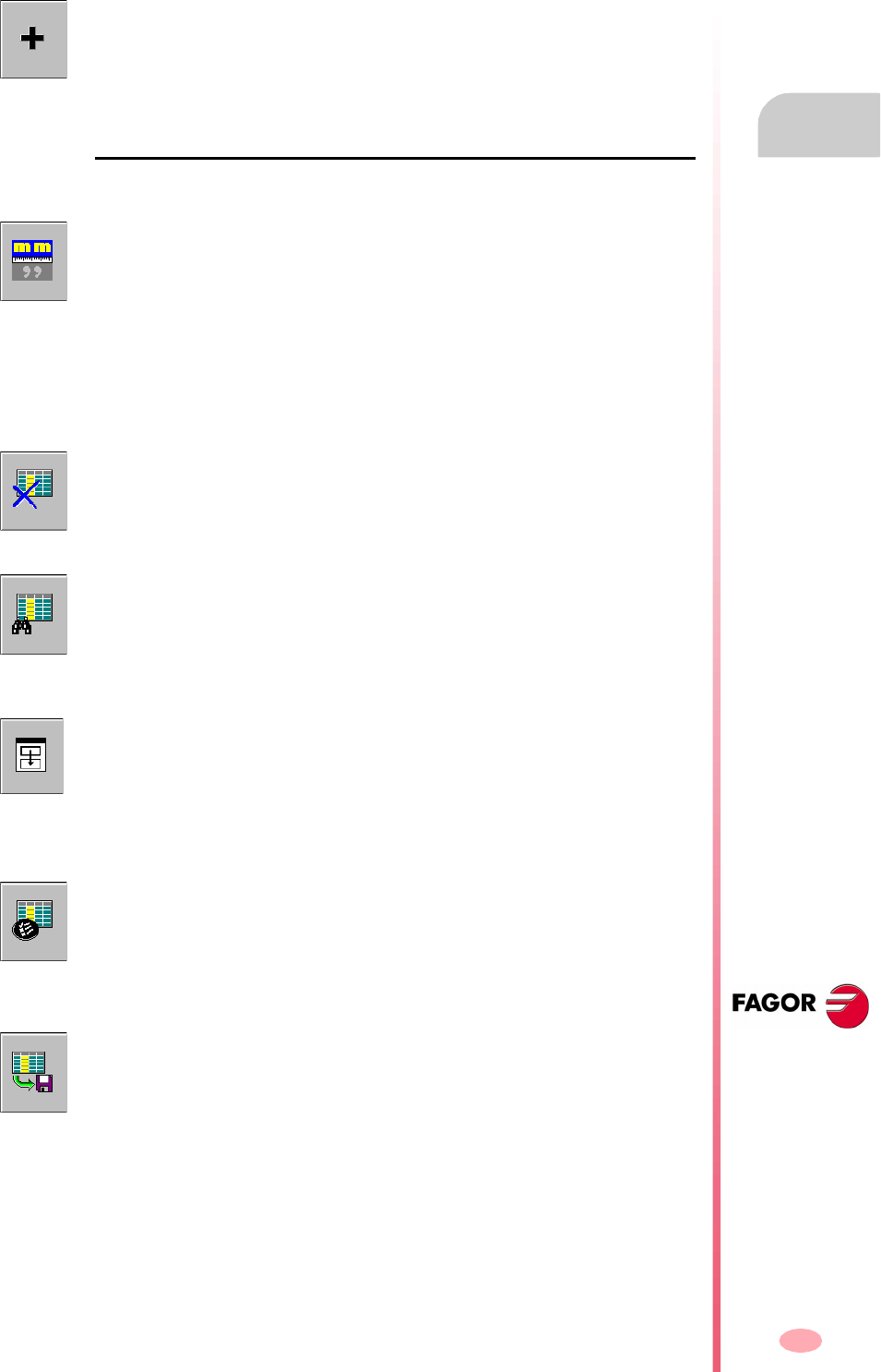
Operating manual
CNC 8070
USER TABLES
Appearance of the table mode
8.
(SOFT V03.0X)
163
8.1.1 Icon description (vertical softkeys)
The icons are activated with their associated softkey (F8 to F12).
List of icons
The icon menu offers all the options for the selected table. The group of icons of this
menu may be expanded with the softkey associated with the "+" icon that offers a new
set of icons.
Display units (millimeters/inches)
To toggle the units for the position of the linear axes. Toggling these units does not
affect the rotary axes which will always be displayed in degrees.
The icon highlights the units currently selected (millimeters or inches).
It must be borne in mind that the unit change is only valid for display and data entry.
A program assumes the units defined with the active function "G70" or "G71", or, when
not programmed, the units set by the machine manufacturer.
Initialize table
Resets all the table data to "0". The CNC will request confirmation of the command.
Find text
It is used to find a text or a value in the table.
When selecting this option, the CNC shows a dialog box requesting the text to be
found.
Accessing the tables of other channels
(This icon will only be available when using channels).
Some tables only show the data of the active channel. This icon gives access to the
tables of the other channels.
Select axes
It may be used to select the axes to be displayed in the tables.
When using several channels, only those axes assigned to the active channel may
be accessed.
Save tool
It saves the values of the table into a file. This file may be saved at the CNC, in a floppy
disk or at another CNC (or PC) connected through Ethernet.
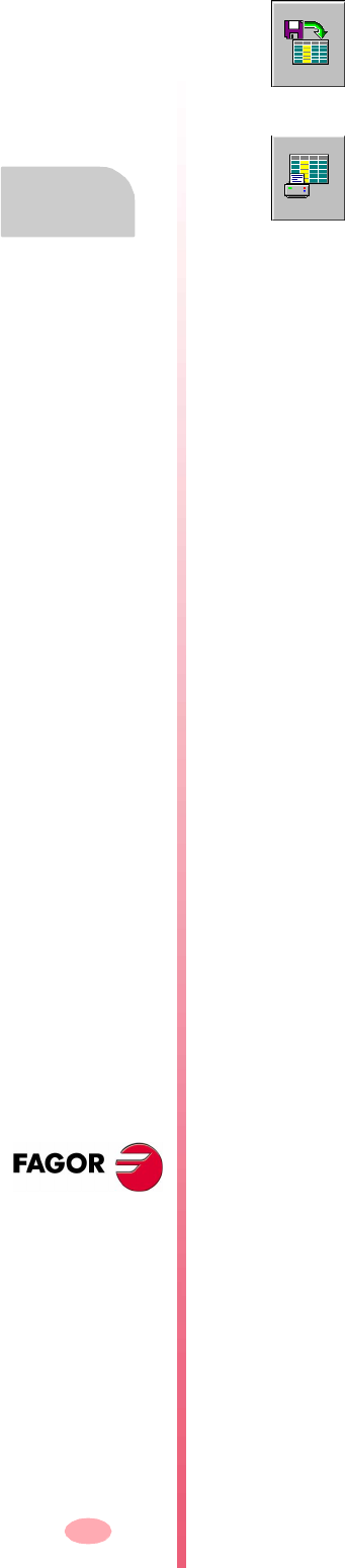
Operating manual
CNC 8070
8.
USER TABLES
Appearance of the table mode
(SOFT V03.0X)
164
Recall table
It restores the values of the table previously saved into a file.
Print table
It prints the contents of the table out to a printer connected to the CNC or as a file
(*.PRN format) at the CNC.
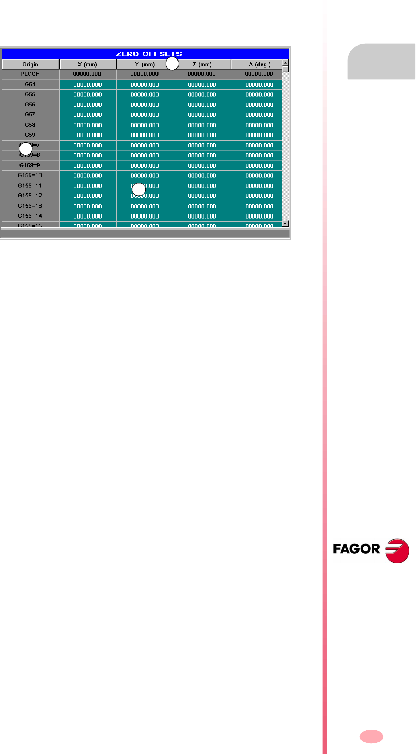
Operating manual
CNC 8070
USER TABLES
Zero offset tables
8.
(SOFT V03.0X)
165
8.2 Zero offset tables
This table stores the zero offsets for each axis. There are up to 20 absolute zero
offsets and a special one for the PLC.
Although the table is common to all the channels, when accessing from a channel,
it only shows the axes of that channel. The offsets of other channels may be accessed
from the vertical softkey menu.
A. Machine axes and display units (millimeters, inches or degrees).
B. Zero offsets.
C. Zero offset value in each axes of the channel.
The end of this chapter describes how to edit this table.
PLC offset
It cannot be directly defined in the table. The values are set from the PLC or from the
part-program using high-level variables.
It is used, for example, to correct deviations originated by machine dilatations.
The CNC always adds the PLC offset to the selected zero offset.
Absolute zero offsets
Besides setting the values directly in the table, they may also be set from the PLC
or via part-program using high-level variables.
The zero offsets are used to place the part zero at different positions of the machine.
When applying a zero offset, the CNC assumes as the new part zero the point set
by the selected zero offset referred to the clamp zero (if active).
To apply an absolute zero offset, it must be activated via program using the relevant
function.
A
B
C
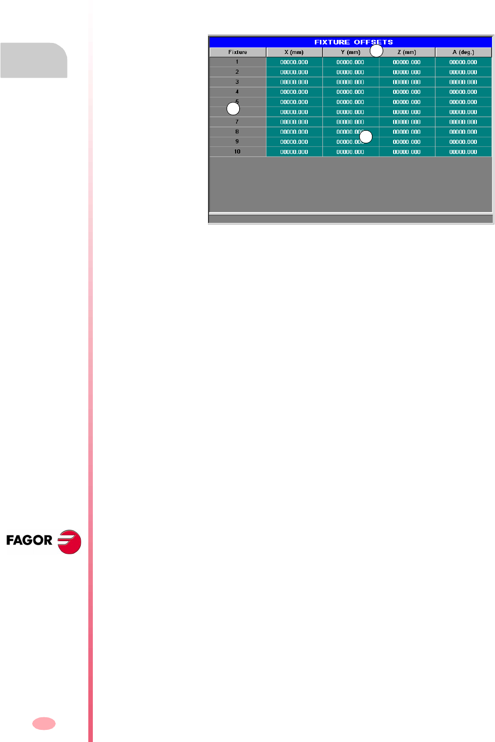
Operating manual
CNC 8070
8.
USER TABLES
Fixture table
(SOFT V03.0X)
166
8.3 Fixture table
This table stores the clamp offsets for each axis. There are up to 10 clamp offsets.
Although the table is common to all the channels, when accessing from a channel,
it only shows the axes of that channel. The offsets of other channels may be accessed
from the vertical softkey menu.
A. Machine axes and display units (millimeters, inches or degrees).
B. Clamp offset.
C. Clamp offset value in each axes of the channel.
The end of this chapter describes how to edit this table.
Fixture offset
Besides setting the values directly in the table, they may also be set from the PLC
or via part-program using high-level variables.
The clamp offsets are used to set the position of the clamping system of the machine.
When applying a clamp offset, the CNC assumes as new clamp zero the point set
by the selected offset referred to machine reference zero (home).
To apply a clamp offset it must be activated from the program using the relevant
variable.
A
B
C
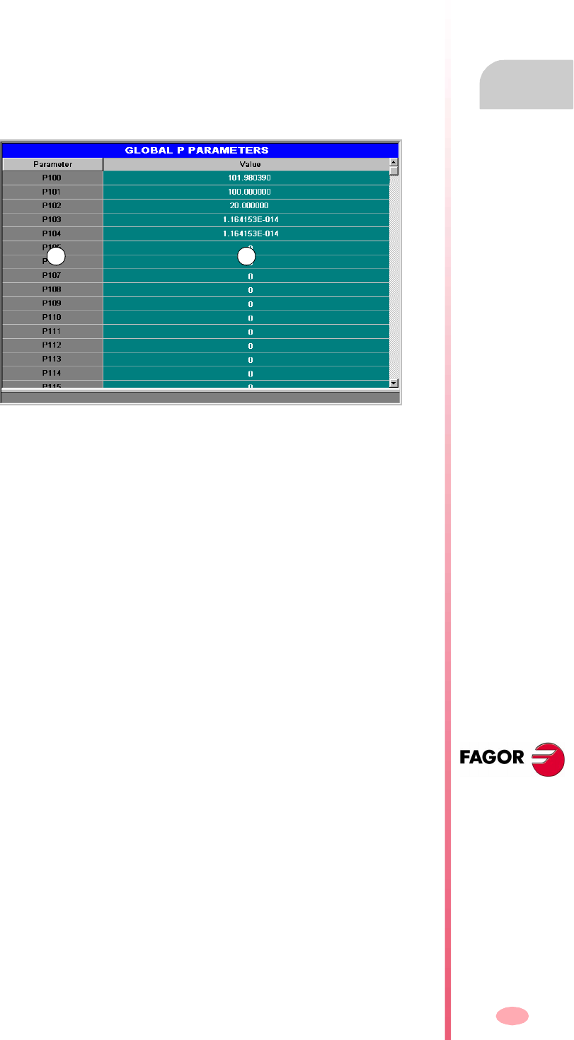
Operating manual
CNC 8070
USER TABLES
Arithmetic parameter tables
8.
(SOFT V03.0X)
167
8.4 Arithmetic parameter tables
There are the following arithmetic parameter tables:
•Common parameters.
•Global parameters.
There is a table for each channel.
•Local parameters.
There are seven tables for each channel, one table per nesting level (7 levels).
The CNC generates a new nesting level for local parameters every time parameters
are assigned to a subroutine.
A. Parameter list.
B. Parameter value.
The end of this chapter describes how to edit these tables.
Arithmetic parameters
The OEM defines the range of local and global parameters up to a maximum of 100
local parameters (P0-P99) and 9900 global parameters (P100-P9999).
When the local parameters are used in a subroutine calling block, they can also be
referred to by the letters A-Z (except "Ñ") in such a way that "A" is the same as P0
and "Z" is the same as P25. That is why the local parameter tables show the parameter
number next to their associated letter.
The parameter values may be set directly in the table or from the PLC or via part-
program. In this case, the table values are updated after carrying out the operations
indicated in the block being executed.
The parameter values may be displayed either in decimal notation (6475.873) or
scientific (0.654E-3).
A B
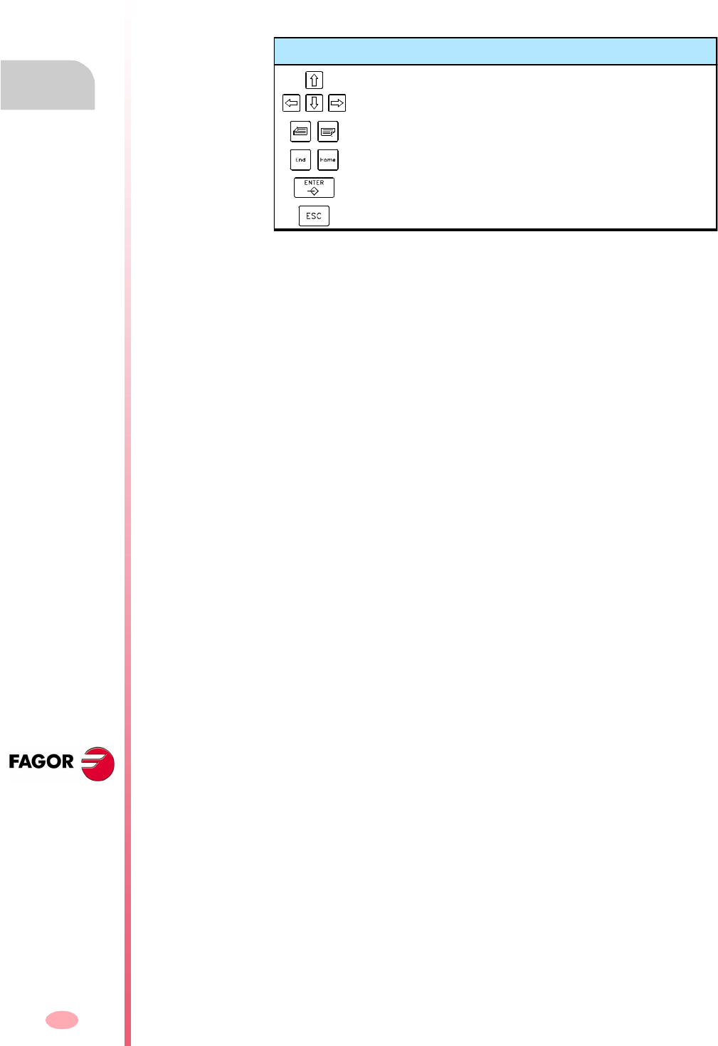
Operating manual
CNC 8070
8.
USER TABLES
Operations with tables
(SOFT V03.0X)
168
8.5 Operations with tables
8.5.1 Data editing
Select the desired table using the softkey menu:
To edit the table data, proceed as follows:
1. Use the cursor to select the cell whose value is to be changed.
2. Key in the new value.
3. Press [ENTER] to accept the new value or [ESC] to ignore the new value and
recover the previous one.
Keys for editing the table data
To move the cursor through the table cells.
To move the cursor page by page.
To move the cursor to the beginning or end of the table.
To validate the new value.
To ignore the defined value.
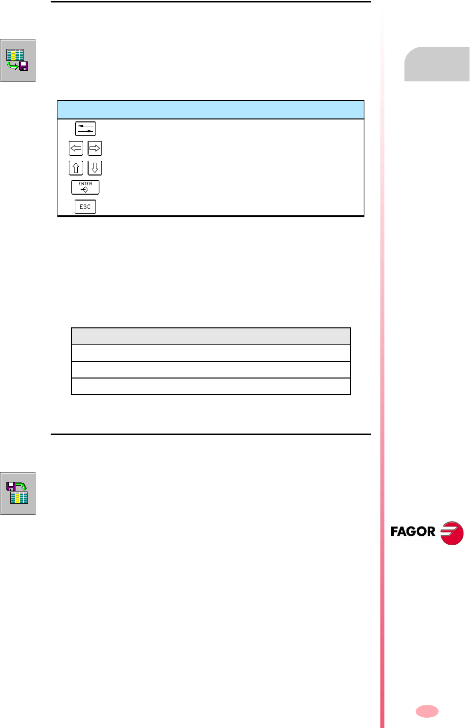
Operating manual
CNC 8070
USER TABLES
Operations with tables
8.
(SOFT V03.0X)
169
8.5.2 Save and recall tables
Saving a table
It may be used to save the table data, in ASCII format, in a file.
To save the table data, proceed as follows:
1. Select the destination folder.
2. Define the file name at the bottom window. To replace an existing file, select it from
the list.
3. Press [ENTER] to save the file or [ESC] to return to the table without saving the file.
Depending on the table being saved, the CNC will assign one of the following
extensions to the file:
Recall a table
It may be used to restore the table data, in ASCII format, from a file.
To recover the table data, proceed as follows:
1. Select the folder containing the file.
2. Select the file from the list or write its name in the bottom window.
3. Press [ENTER] to recall the data from the file or [ESC] to return to the table without
recalling the data.
After selecting the table whose data is to be saved, press the SAVE icon and the CNC
shows a list with the tables that are already saved.
Extension Table type
*.UPO Zero offset table.
*.UPF Fixture table.
*.UPP Parameter tables.
Keys for selecting a data file
To switch windows.
To close and open a folder submenu.
To move the cursor thru the elements of the window.
To save the new program.
To cancel the selection and close the programs listing.
After selecting the table whose data is to be restored, press the LOAD icon and the
CNC shows a list with the tables that are already saved.
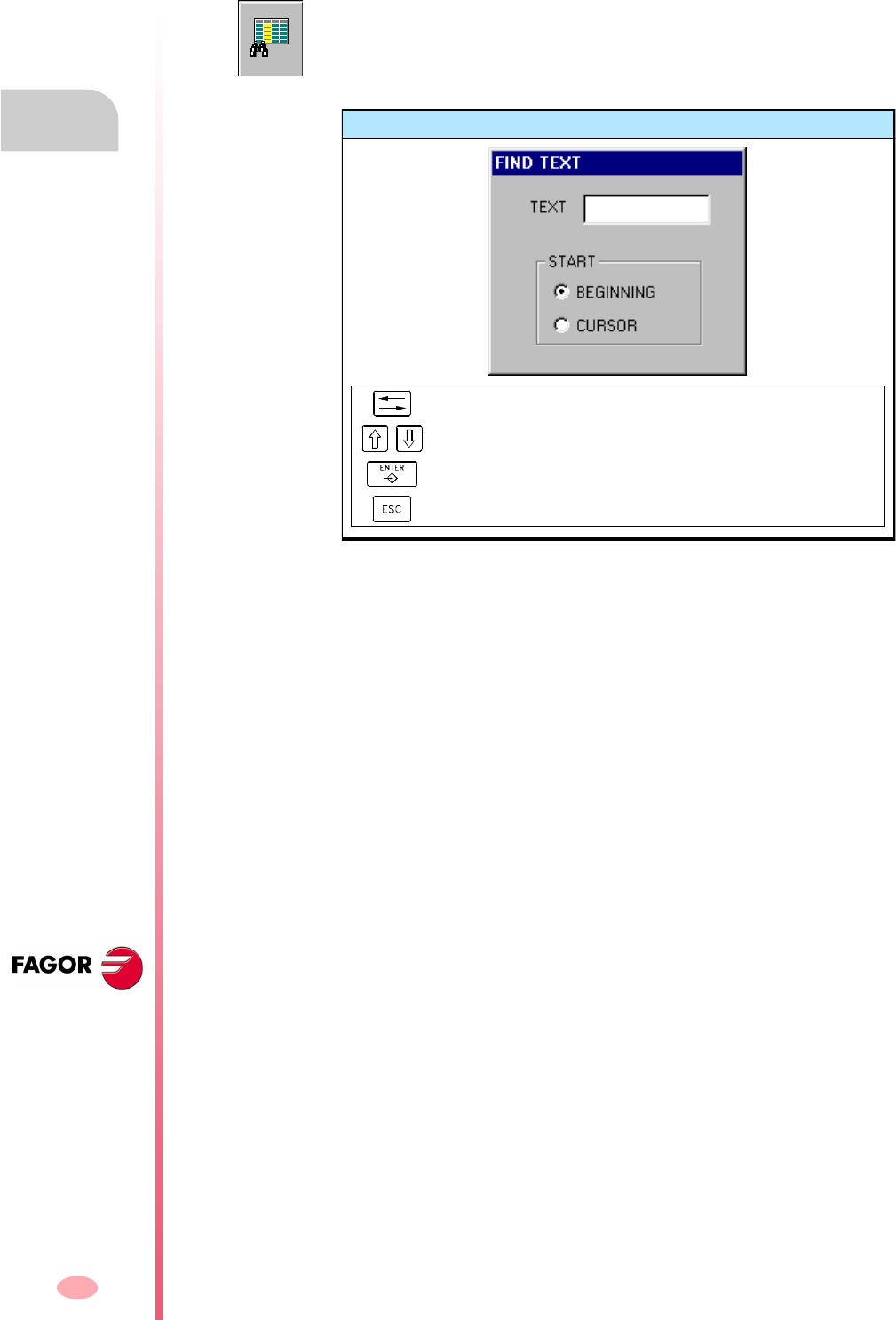
Operating manual
CNC 8070
8.
USER TABLES
Operations with tables
(SOFT V03.0X)
170
8.5.3 Find text
It is used to find text or a value in the table.
To perform the search, press the FIND icon and the CNC will show a dialog box
requesting the text or value to be searched. It is also possible to select whether the
search must start at the beginning of the table or at the current cursor position.
Find text
To move the cursor through the elements of the list.
It selects an option from a group.
To start the search.
To cancel the search and close the dialog box.
171
CNC 8070
(SOFT V03.0X)
9
TOOL AND MAGAZINE TABLE
Selecting the tool tables and magazine tables.
They may be divided into the following tables:
•Tool table.
•Active-tools table.
•Table for the status of the tool change process.
•Tool magazine tables.
In order to load a tool in the magazine or in the spindle, that tool must have been
previously defined in the corresponding table of the CNC.
What can you do in this work mode?
The following operations are possible in this work mode:
•Editing and modifying the tool table
•Display and manage the tool arrangement in the magazines and in the tool
changing arms (if any).
•Display the information about the tool change process; the operation carried out
when executing an M06, manager status, change status (in execution or at rest),
magazine involved in the change (if the change is taking place) and whether the
change process is or not in an error state.
•Load and unload a tool from the magazines through the spindle, using a
maneuver.
•Saving the table contents.
•Recalling the table contents.
•Printing the table contents.
•Initializing the tables.
The CNC tables may be accessed from any other operating mode, even while a
program is in execution, by pressing the key for these tables.
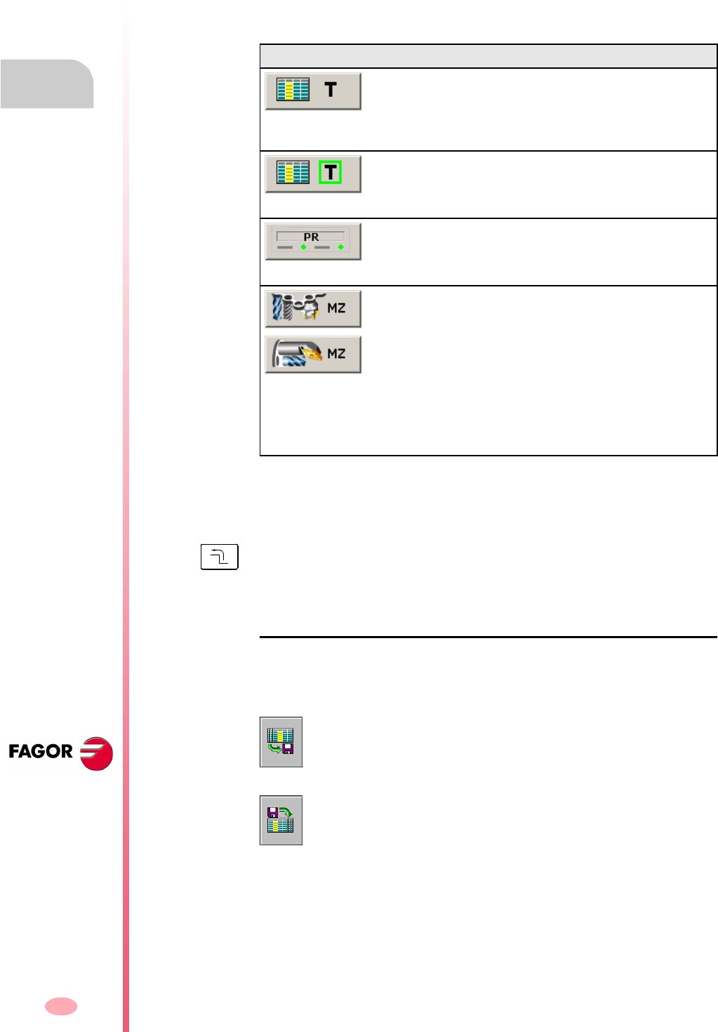
Operating manual
CNC 8070
9.
TOOL AND MAGAZINE TABLE
Showing tables and common operations
(SOFT V03.0X)
172
9.1 Showing tables and common operations
9.1.1 Table selection
This operating mode consists of several tables. The various tables may be selected
using the horizontal softkeys.
When selecting one of these tables, it is displayed on the screen and the vertical icon
menu shows the icons associated with that table. Later sections of this chapter show
a more detailed description of the icons and operations that may be carried out in each
table.
Simultaneous operations for all the tables
If no table is currently selected, the vertical softkey menu will show the following
softkeys to save or load all the tables. See "9.1.3 Save and load the tables" on page
174.
Softkey Table
Tool table.
This table defines the tools available and the data associated
with each one of them. This table is common to all the
magazines.
Active-tools table.
This table shows the tool that is active in each channel and the
data associated with it.
Change process.
This table monitors the tool changes being executed in each
channel.
Tool magazine table (there is one table per magazine)
For each magazine, it shows the tool distribution and the
remaining life time of each tool (if tool life monitoring is active).
If the magazine has a changer arm, it shows the tool located
in it.
The description of the magazine type can also be shown.
The icon associated with this table depends on the software
configuration (lathe or mill).
Pressing the key for the previous menu deselects the active table. When no table has
been selected, the vertical icon menu may be used to save and restore all the tables.
Save the tables
Saves the data of all the tables.
Recall the tables
It restores the data previously saved for all the tables.
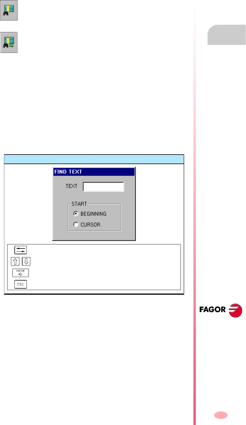
Operating manual
CNC 8070
TOOL AND MAGAZINE TABLE
Showing tables and common operations
9.
(SOFT V03.0X)
173
9.1.2 Search for a text in the tables
It is possible to search for a text or a value in the list of tools and magazine positions.
The search is carried out from the vertical softkey menu.
To start or resume the search, press [ENTER] and the focus will position on the first
match found. Every time one of the icons is pressed, it offers the option to search for
the next match or to define a new search.
The search may be canceled by pressing the [ESC] key.
Define the search criteria.
Every time one of these icons is pressed, it shows a dialog box to define the search
criteria. The following may be defined in this dialog box:
•The text or value to search for.
•The beginning point of the search, namely either from the beginning of the table
or from the cursor position.
This icon starts the search. Once the icon has been pressed, the CNC will
display a dialog box to define the search criteria. The defined criteria is
maintained until a new one is defined.
This icon is shown when a search criteria has been defined; it makes it
possible to search for the next match using the current search criteria.
Find text
To move the cursor through the elements of the list.
It selects an option from a group.
To start the search.
To cancel the search and close the dialog box.
Operating manual
CNC 8070
9.
TOOL AND MAGAZINE TABLE
Showing tables and common operations
(SOFT V03.0X)
174
9.1.3 Save and load the tables
From the vertical softkey menu, it is possible to make a backup copy of the table data
(recommended). With these files, it is possible to recover the table data when needed.
These tables are saved in the an ASCII file. These files may be saved at the CNC,
in a floppy disk or at another device (CNC, PC, etc.) connected through Ethernet. By
default, they are saved in the folder "C:\CNC8070\ MTB\ DATA" or in the last folder
selected by the user.
These tables are saved in the following files. The table monitoring the change
processes is informative only; it is not copied anywhere.
Considerations for saving and loading tables.
Although each table may be saved separately, it is recommended to always have a
copy of all the tables. Also, the following must be borne in mind when loading the
tables:
•Loading the tool table initializes the magazine tables and the active-tools table.
When changing the list of available tools, it may not be coherent with the tool
distribution in the magazine or in the spindles. This is why after loading this table
it is necessary to define (or load) the magazine tables and the active-tools table,
if any, in that order.
•Loading the magazine table initializes the active-tools table. This is because when
loading the magazine tables, the new tool arrangement may not be coherent with
the active tools. This is why after loading this table, it is necessary to load the
active-tools table.
Save the tables
The tables may be saved one by one or all of them simultaneously. In either case,
the action is carried out from the vertical softkey menu using one of the following icons.
After pressing the icon, the CNC will ask where to save the data files. Select the
desired folder and press [ENTER]. The selection process may be canceled by
pressing the [ESC] key.
Table File
Tool table. Tools.TPT
Active-tools table. Toolsact.TPA
Tool magazine table (if there is only one magazine). Magazine.TPM
Tool magazine table (if there are several magazines). Magazine1.TPM
· · ·
Magazine4.TPM
Saving all the tables at the same time.
To save all the tables at the same time, no table must be selected. See
"9.1.1 Table selection" on page 172.
Saving each table separately.
To save the tables one by one, select each table from the horizontal softkey
menu.
Operating manual
CNC 8070
TOOL AND MAGAZINE TABLE
Showing tables and common operations
9.
(SOFT V03.0X)
175
Recall the tables
It may be used to restore the data, in ASCII format, of the tables from the files. The
tables may be loaded one by one or all of them simultaneously. In either case, the
action is carried out from the vertical softkey menu using one of the following icons.
After pressing the icon, the CNC will ask the location of the data files. Select the
desired folder and press [ENTER]. The selection process may be canceled by
pressing the [ESC] key.
Order (sequence) to follow when loading the different tables.
As mentioned earlier, there are two ways to load the table data from the ASCII files;
loading all of them at the same time or selecting each table and loading its data.
Loading all the tables at the same time.
In this case, it is up to the CNC to set the order (sequence) used to load the data.
Order (sequence) to follow when loading the tables one by one.
This way, each table is selected and its data loaded. In this case, the following
sequence must be followed when loading the tables.
1. First load the tool table.
This table defines the system tools. Loading the tool table initializes the tables of
the magazines and the active-tools table.
2. Second, load the tool magazine tables.
Since the tool list has changed, if the magazine tables are not loaded, it is not
possible to assure that the new tools are the ones located in the magazine tool
or in the active-tools table.
3. Finally, load the active-tools table.
When loading the tables of magazines, it is unsure that the current tool positions
will be compatible with the active tools.
Loading all the tables at the same time.
To load all the tables at the same time, no table must be selected. See
"9.1.1 Table selection" on page 172.
Loading each table separately.
To load the tables one by one, select each table from the horizontal softkey
menu. To load the data of all the tables (recommended), follow a particular
loading order to guarantee data consistency.
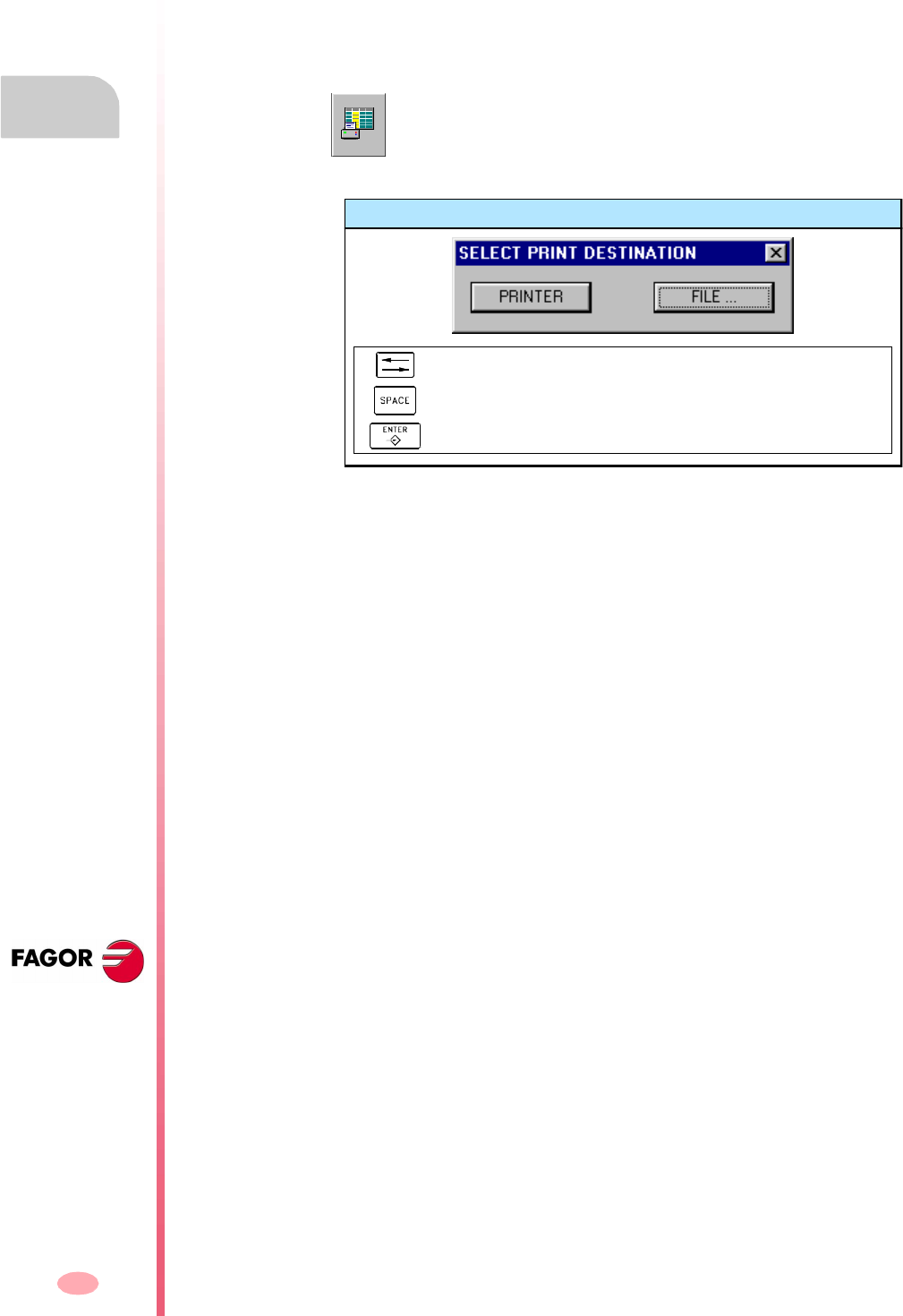
Operating manual
CNC 8070
9.
TOOL AND MAGAZINE TABLE
Showing tables and common operations
(SOFT V03.0X)
176
9.1.4 Printing the tables
Some of the tables may be printed in a printer accessible from the CNC or as a file
(PRN format). When the tables are saved as a file, it may be saved at the CNC, in
a floppy disk or at any other device (CNC, PC, etc.) connected through Ethernet. By
default, the files are saved in the folder "C:\CNC8070\ USERS\ Reports".
In either case, the action is carried out from the vertical softkey menu using the
following icon.
After selecting the target, press [ENTER] to start printing. Press [ESC] to cancel the
selection.
This icon starts printing. When pressing this icon, the CNC will show a
dialog box requesting the print destination for the table (printer or file).
Print destination
To select the print destination.
To print the drawing.
To cancel the printing.
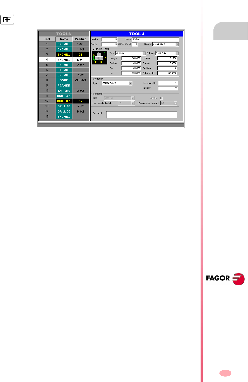
Operating manual
CNC 8070
TOOL AND MAGAZINE TABLE
Tool table
9.
(SOFT V03.0X)
177
9.2 Tool table
This table defines the tools available and the data associated with each one of them.
The tool list is common to the whole system, i.e. is common to all the available
magazines. Once the tools have been defined, they may be distributed in the various
magazines.
The left panel shows the list of available tools. For each tool, it indicates the position
and the magazine where it is located, whether it is a ground tool or the tool is active
in a channel.
The right panel shows the data of the tool selected on the list. From the vertical softkey
menu, it is possible to select the data shown on the right panel. See
"9.2.3 Description of the tool data" on page 181.
About the tools
Each tool is identified by its number, that is unique for the whole system; it cannot
be repeated in different magazines nor in ground tools. This table indicates the
position and the magazine where each tool is located, whether it is a ground tool or
the tool is active in a channel.
Ground tools
A ground tool is a tool that is not stored in any magazine and is loaded manually when
requested. Ground tools are also defined in the tool table, but they are not associated
with any magazine position.
Ground tool loading and unloading is global to the system; it is not associated with
any particular magazine or channel.
The table is divided in two panels. To switch panels, press the panel-change key.
Operating manual
CNC 8070
9.
TOOL AND MAGAZINE TABLE
Tool table
(SOFT V03.0X)
178
9.2.1 Description of the icons of the vertical softkey menu
The options of the vertical menuof softkeys depend on which table is active.
The options shown for the tool table are. Bear in mind that the table is divided into
two panels. There are options that are valid for both panels and options that are only
available on one of them.
The vertical softkey menu shows all the options for the selected table. The group of
options shown on this menu may be expanded with the softkey associated with the
"+" icon that offers a different set of options.
Display units (millimeters/inches)
It is used to change the units for data display. The change of units is only valid for
display and data entry. For programming, the CNC assumes the units set by the active
function G70 or G71.
The icon highlights the units currently selected (millimeters or inches).
Find text
To search for a text on a tool list. See "9.1.2 Search for a text in the tables" on page
173.
Add tool
(This icon is only available for the tool list).
It adds a new tool to the list.
Delete tool
(This icon is only available for the tool list).
It removes a tool from the list. A tool cannot be deleted if it is in the tool magazine.
Delete data
(This icon is only available for tool data).
It deletes the data where the cursor is. When deleting a data, it assumes its default
value.
Configuring the tool table
(This icon is only available for tool data).
It is used to configure the data shown in the tool table.
Initializing the table
(The table can only be initialized when the CNC is "READY").
It initializes the tool table. The CNC will request confirmation of the command.
Initializing the tables eliminates all the tools from the list. It also initializes the active-
tools table and the magazine tables because the available tools have been erased.
Save table
It saves the table data in a file. See "9.1.3 Save and load the tables" on page 174.

Operating manual
CNC 8070
TOOL AND MAGAZINE TABLE
Tool table
9.
(SOFT V03.0X)
179
Recall table
It recalls the table data previously saved in a file. See "9.1.3 Save and load the
tables" on page 174.
Bear in mind that loading the tool table initializes the magazine tables and the active-
tools table.
Print table
It prints the contents of the table out to a printer connected to the CNC or as a file
(PRN format) at the CNC. See "9.1.4 Printing the tables" on page 176.
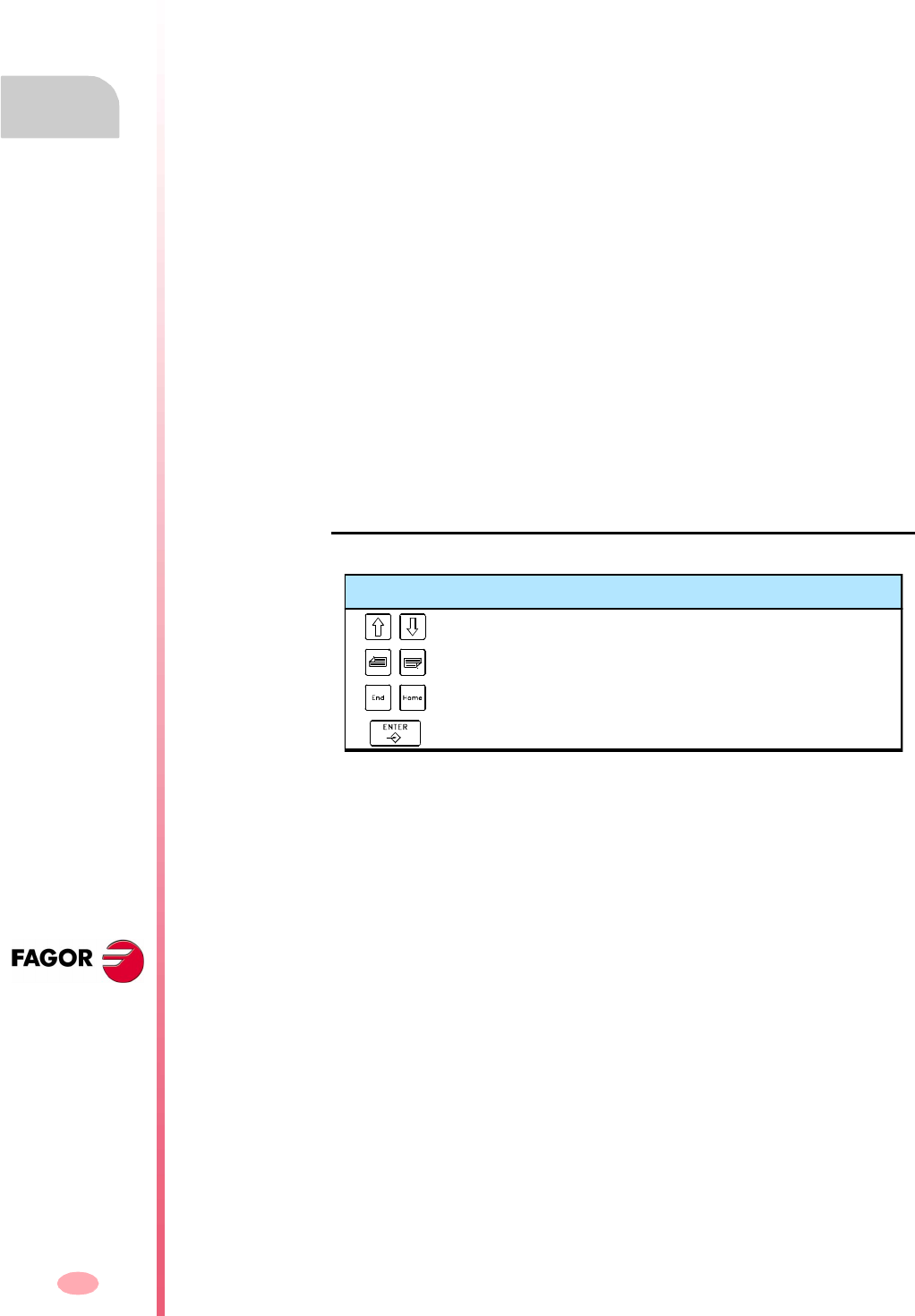
Operating manual
CNC 8070
9.
TOOL AND MAGAZINE TABLE
Tool table
(SOFT V03.0X)
180
9.2.2 The tool list
The tool list appears on the left panel of the tool table. The list shows the available
tools and their position. The CNC updates data of the list every time a tool change
is carried out.
Tool number
It is assigned automatically when the tool is added to the list. It may be modified by
the user in the data window.
Tool name
Name identifying the tool defined by the user in the data window. It may be edited
directly on the list.
Tool position
It indicates the position of the tool, in a magazine, in the spindle or in the claws of
the tool changer arm.
C1-C4 It is in one of the spindles.
M1-M4 It is in one of the magazines. In this case, it also indicates its
magazine position.
CH1-CH2 It is in the holders of the tool changer arm.
If none of these positions is indicated, it means that it is a ground tool. Ground tools
are not stored in the magazine and are loaded manually when requested.
How to move around on the tool list
Keys to select a tool from the list
To scroll list up and down line by line.
To move the cursor page by page through the list.
To move the cursor to the beginning or end of the list.
To access the data of the selected tool.
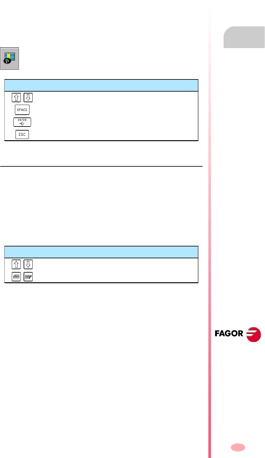
Operating manual
CNC 8070
TOOL AND MAGAZINE TABLE
Tool table
9.
(SOFT V03.0X)
181
9.2.3 Description of the tool data
The tool data appears on the right panel of the tool table. It shows the data of the tool
selected on the list.
This data must be defined by the user. When using tool life monitoring, the CNC is
in charge of updating the value of the actual (real) life.
Configuring the tool data display
The data being shown may be configured from the vertical softkey menu.
Description of the tool data
The tool data is grouped as follows:
•Tool identification.
•Tool geometry.
•Tool monitoring.
•Information for the magazine.
•Custom.
•Comment.
Tool identification
Information identifying the tool: number, name, family, number of tool offsets and
status.
Tool number
It is assigned automatically when the tool is added to the list. This number may be
changed if it is not in the magazine, in the spindle or on the tool changer arm.
The tool number may be any integer between 1 and 999999999; by default, it is
assigned the first available value on the list.
When entering an existing tool number, the CNC displays the data for that tool.
When pressing this icon, the CNC shows a dialog box for selecting the data
to be shown. To hide a data, cancel the relevant check box.
Keys to set the tool table
To move the cursor.
To activate/deactivate the selection box.
To accept the configuration defined.
To cancel the defined configuration.
Keys for selecting the table data
It selects the previous and next data of the same group.
It selects the first data of the previous or next group.
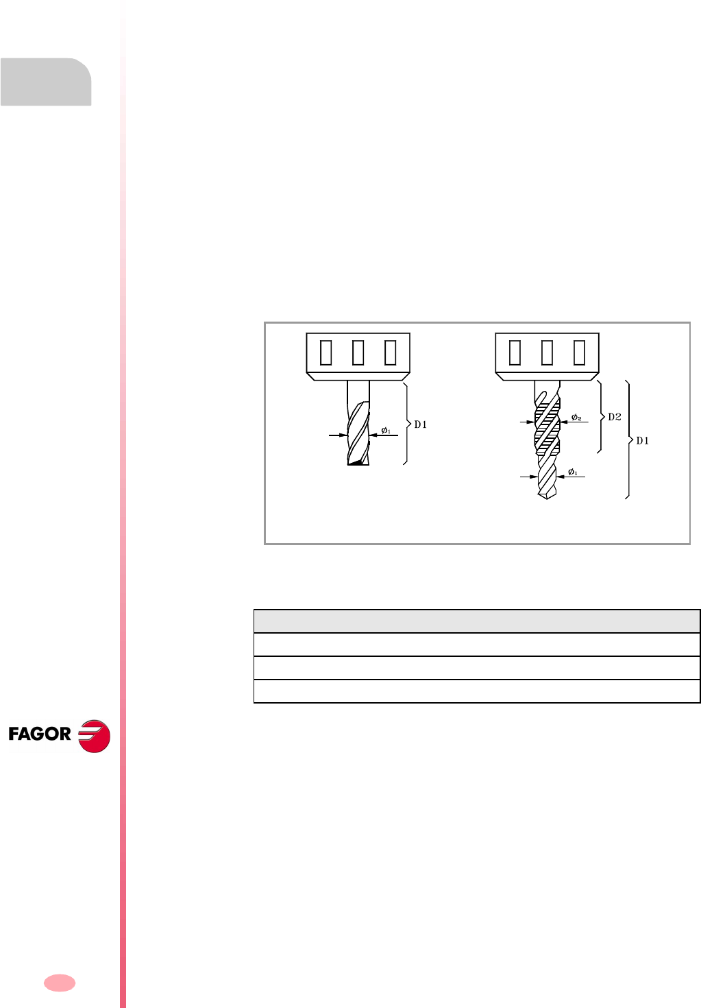
Operating manual
CNC 8070
9.
TOOL AND MAGAZINE TABLE
Tool table
(SOFT V03.0X)
182
Tool name
Name identifying the tool. This data can also be defined on the tool list.
The tool name may be up to 32-characters long.
Tool family
A tool family is a group of tools that share similar characteristics. This information is
used when using an automatic tool changer so the CNC can replace the worn-out
or rejected tool with a similar one.
When requesting a new tool, the CNC checks whether it is worn out (real life greater
than nominal life) or it has been rejected. If so, it selects the next tool in the table that
belongs to the same family.
The family or a tool may be any integer between 0 and 99999999. The ·0· family is
the same as not having a family; i.e. the tools belonging to the ·0· family cannot be
replaced with another one.
Tool offsets
Number of tool offsets. Each tool offset has different geometry and monitory data
associated with it.
A tool can have up to 8 offsets. When a tool has several offsets, their numbers must
be correlative (non-skipping).
Tool status
It indicates the tool status. The possible status are:
When using tool life monitoring, the "worn-out" and "rejected" indicators are also set
by the CNC when any of the previous cases occur.
Status Meaning
Available The tool is available.
Worn out The "real life" is greater than the "nominal life".
Rejected The tool has been rejected by the PLC.
Example of a milling tool with one offset (left) and two offsets (right).
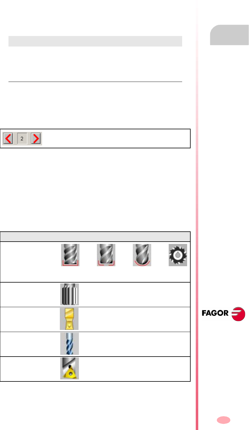
Operating manual
CNC 8070
TOOL AND MAGAZINE TABLE
Tool table
9.
(SOFT V03.0X)
183
Tool geometry
This area shows the data about the tool type and its dimensions. The geometry data
depends on the type of tool. The table only shows the data that makes sense for the
selected tool.
While defining the data, it shows various information graphics depending on the data
being defined. On the other hand, the bottom of the screen shows the description of
the data currently selected.
The data related to the geometry may be accessed with the following hotkeys:
Offset selection
The geometry data is associated with the tool offset. If the tool has been defined with
several offsets, it shows the number of the offset whose data is displayed, and it also
allows selecting the previous or next offset. To change offsets, place the focus on the
buttons and press [SPACE].
Operation type and tool
Regardless of the software installed, it is possible to define both milling and lathe
tools. The tool is defined depending on the operation it can carry out. If it is not the
right tool for any of the proposed operations, it must be assigned the operation
"Others".
Once the operation has been selected, the screen will show the available tools. It will
show a help graphic with the selected tool type.
The data to define the geometry of the tool will be relevant to the selected tool. It will
only show the data that makes sense for the selected tool.
Hotkey Access
L Length, length wear and edge length.
R Radius, radius wear, nose (tip) radius and nose (tip) radius wear.
A Penetration angle
O Offsets on each axis.
Offset number and selection of the previous or next offset. In
this case, it will display the data of the second tool offset.
Operation Tool type
Milling
(A) Flat endmill.
(B) Toric endmill.
(C) Ball endmill.
(D) Disk endmill.
Reaming
(A) Reamer.
Grooving/cutoff
(A) Square.
Drilling
(A) Drill bit.
Boring
(A) Quill.
(A) (B) (C) (D)
(A)
(A)
(A)
(A)
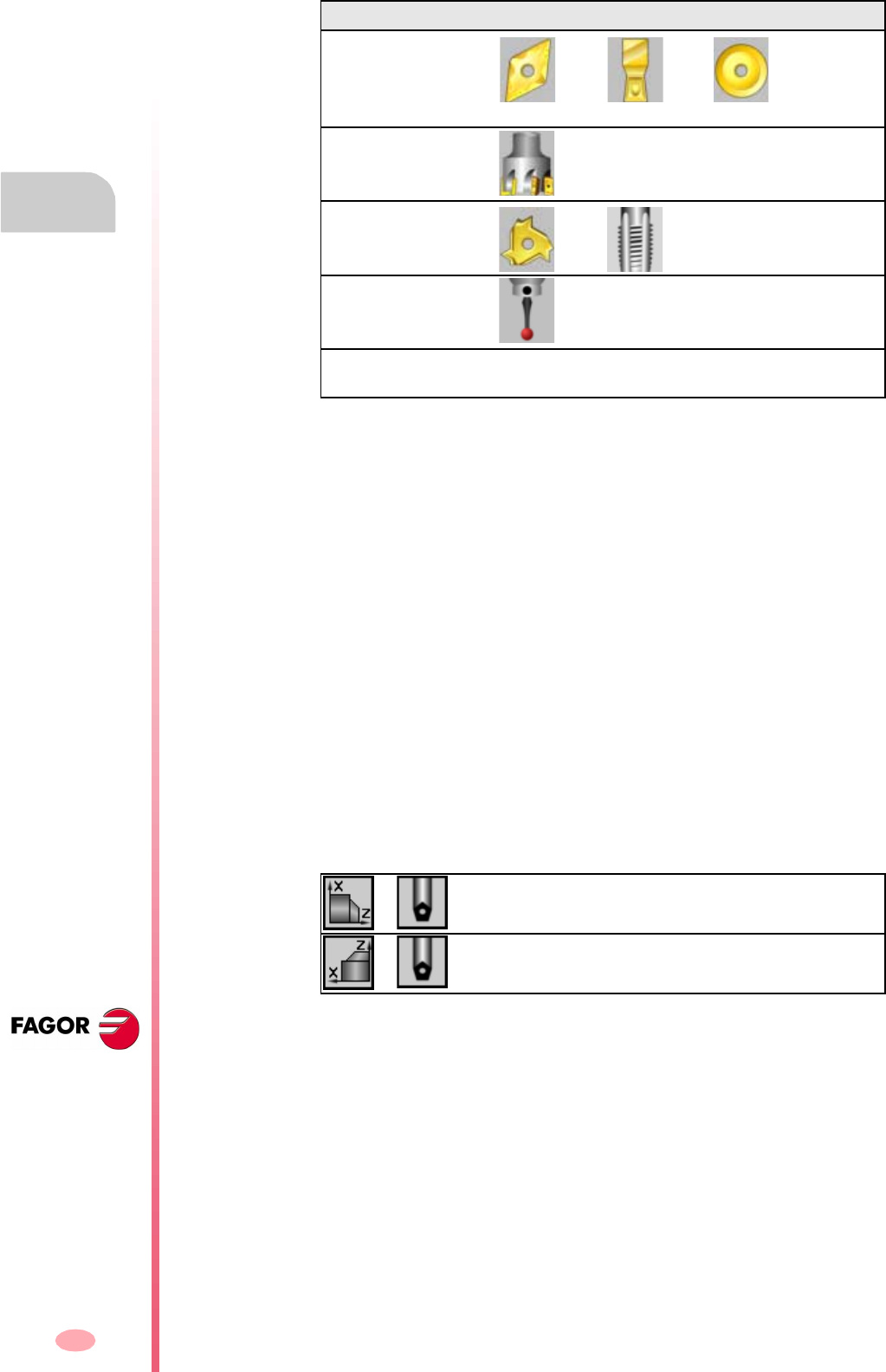
Operating manual
CNC 8070
9.
TOOL AND MAGAZINE TABLE
Tool table
(SOFT V03.0X)
184
Axis orientation in turning.
It is defined with an icon that is only displayed when defining a turning (lathe) tool.
The orientation of the axes is determined by the type of lathe (horizontal or vertical),
the position of the turret and the spindle position (on the right or on the left).
Location code or tool calibration point.
It is defined with an icon that is only displayed when defining a turning (lathe) tool.
The location code indicates which is the calibrated tool tip and, therefore, the point
controlled by the CNC to apply radius compensation. The location code depends on
the orientation of the machine axes.
Tool-holder orientation.
It is defined by an icon that is displayed in the following cases.
•On a lathe model, for all the tools.
•On a mill model, only for turning (lathe) tools.
The orientation of the tool holder indicates whether it is a tool for horizontal or radial
machining. For turning tools, the meaning of this icon depends on the orientation of
the tool axes.
Tur n in g
(A) Diamond.
(B) Square.
(C) Round.
Surface milling
(A) Surface milling
endmill.
Tapping
(A) Cutter.
(B) Tap.
Measuring probe
Others To define the tools that do are not suitable for the
proposed operations.
Horizontal lathe. Radial machining.
Vertical lathe. Longitudinal machining.
Operation Tool type
(A) (B) (C)
(A)
(A) (B)
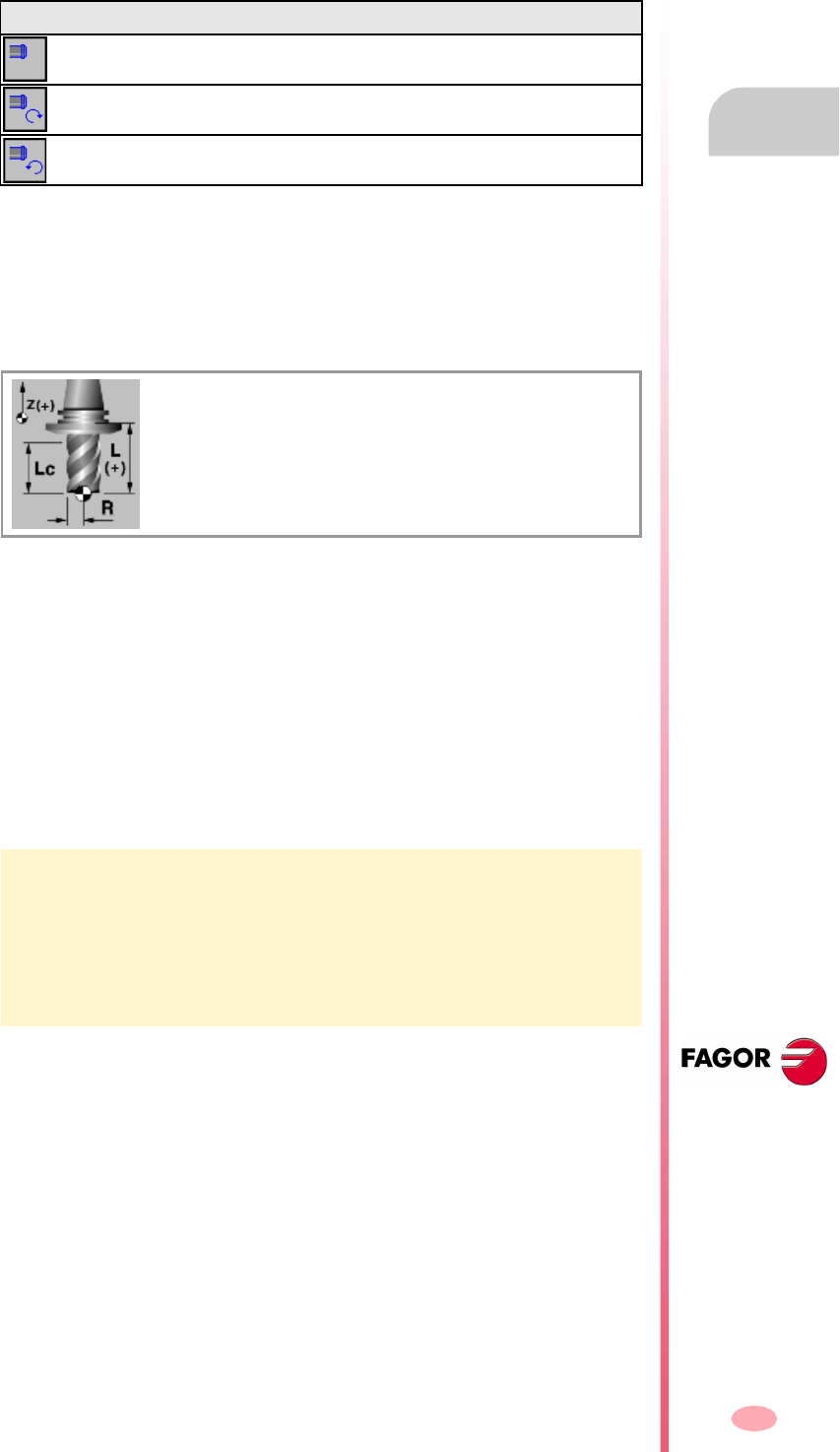
Operating manual
CNC 8070
TOOL AND MAGAZINE TABLE
Tool table
9.
(SOFT V03.0X)
185
Machining direction.
It is defined with an icon.
It indicates the tool's machining direction.
"L" - Tool length
This data is only shown on tools that are not for turning.
"R" - Tool radius
This data is only shown on tools that are not for turning.
"LW" - Length wear
Tool length wear offset. This data is only shown on tools that are not for turning.
The CNC will add this value to the nominal length to calculate the real tool length
("Length" + "L wear").
"RW" - Radius wear
Tool radius wear offset. This data is only shown on tools that are not for turning.
The CNC will add this value to the nominal radius to calculate the actual (real) tool
radius ("Radius" + "R wear").
"A" - Cutter angle
This data is only shown for turning tools.
"C" - Cutting angle
This data is only shown for turning tools.
Icon Machining direction.
Undefined direction.
Right-hand machining direction.
Left-hand machining direction.
A tool with a radius of 20mm and a length of 134mm has a radius wear of 0.2mm
and a length wear of 0.15mm, the tool table should be set as follows:
Radius = 20 mm. Wear R = -0.2 mm.
Length = 134 mm. Wear L = -0.15 mm.
The CNC assumes as real dimensions the following.
Real radius => 20 + (-0.2) = 19.8mm.
Real length => 134 + (-0.15) = 133.85 mm.
L Tool length.
R Tool radius.
Lc Cutting length.
Operating manual
CNC 8070
9.
TOOL AND MAGAZINE TABLE
Tool table
(SOFT V03.0X)
186
"B" - Cutter width
This data is only shown for turning tools.
"Rp" - Tool tip radius
Tool tip radius.
"RpW" - Tool tip radius wear
Tool tip radius wear.
The CNC will add this value to the nominal tool tip radius to calculate the actual (real)
tool tip radius ("Rp" + "Rp wear").
"Lc" - Cutting length
Length of the cutting edge.
"Ae" - Entry angle
This data is only shown on tools that are not for turning.
Penetration angle for pocket milling.
Tool offsets
On milling tools, it is used to define the tool position when using a tool holder or an
intermediate tooling.
On turning tools, it is used to define the tool length in each axis.
Tool offset wear
Tool offset distance.
A Cutter angle.
C Cutting angle.
B Cutter width.
Lc Cutting length.
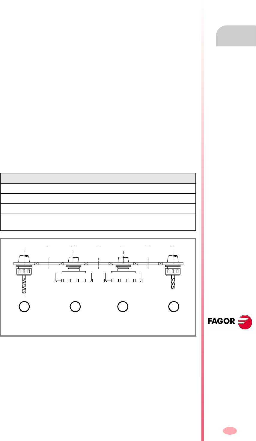
Operating manual
CNC 8070
TOOL AND MAGAZINE TABLE
Tool table
9.
(SOFT V03.0X)
187
Tool life monitoring
This group shows the data related to tool life monitoring. If a tool has been defined
with several offsets, it is possible to manage the status of each one.
When managing the live of two or more offsets of the same tool, the list of the
magazine positions (magazine table) only shows whether the tool has been rejected
or not.
Type
It is used to activate and select the type of tool life monitoring (in time or number of
operations).
Nominal life
Machining time (in minutes) or number of operations that the tool may carry out.
Real (actual) life
Machining time or number of operation the tool has carried out. The CNC updates
this value when the tool is being used.
Tool magazine
This information cannot be modified if the tool is in the spindle, on the changer arm
or in the magazine.
Size
Tool size. The size determines the number of positions (pockets) the tool occupies
in the magazine.
Positions to the right / Positions to the left
Space reserved in the magazine for the tool to the right and to the left of its position.
This data can be defined when the tool size is "custom".
Size Magazine positions it occupies.
Small It only occupies its position. It takes no extra position.
Medium It takes half of an additional position to the right and to the left.
Large It takes a full additional position to the right and to the left.
Custom The user defines the number of additional positions the tool
occupies to its right and to its left.
(A) Small tool.
(B) Large tool.
1234567
A ABB

Operating manual
CNC 8070
9.
TOOL AND MAGAZINE TABLE
Tool table
(SOFT V03.0X)
188
Special
The tool always occupies the same position in the magazine.
Custom
Data defined by the manufacturer.
Data 1 / Data 2
These data show, in numerical format, the information selected by the manufacturer.
Data 3 / Data 4
These data show, in binary format, the information selected by the manufacturer.
Comment
Comment associated with the tool.
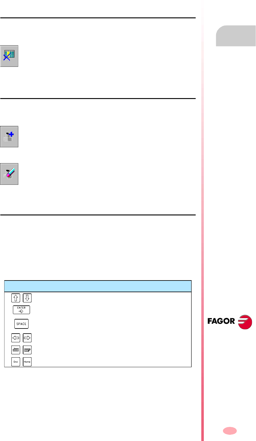
Operating manual
CNC 8070
TOOL AND MAGAZINE TABLE
Operations with the tool table
9.
(SOFT V03.0X)
189
9.3 Operations with the tool table
9.3.1 Editing the tool table
Initialize table
The table can only be initialized when the CNC is "READY". The table is initialized
from the vertical softkey menu.
Adding/removing a tool to/from the list
A tool may be added or deleted only when it is selected on the tool list. Both operations
are carried out from the vertical softkey menu.
Data editing
Proceed as follows to fill out the tool table data:
1. Select the tool to be set from the list and press [ENTER] to access its data.
2. Configure the table to show only the data that may be defined hiding the rest.
3. Define the tool data. Every time a new value is defined, press [ENTER] to validate
it.
4. Make a safety backup copy of the tool data out to a file.
When resetting the table, all the tools are deleted from the list, including
those in the spindle and on the tool changer arm. It also initializes the
active-tools table and the magazine tables because the available tools
have been erased.
Add a tool to the list.
It adds a new tool to the list. The tool is added to the list at the first free
position.
Remove a tool from the list.
It removes a tool from the list. A tool cannot be removed if it is in the
magazine, in the spindle or on the tool changer arm.
Keys for tool table editing
To move the cursor through the table data.
To validate the new value.
To activate/deactivate the selection boxes and open/close drop
lists.
To move the cursor whitin a data.
To select the line before or after the comment.
To move the cursor to the beginning or end of the comment line.
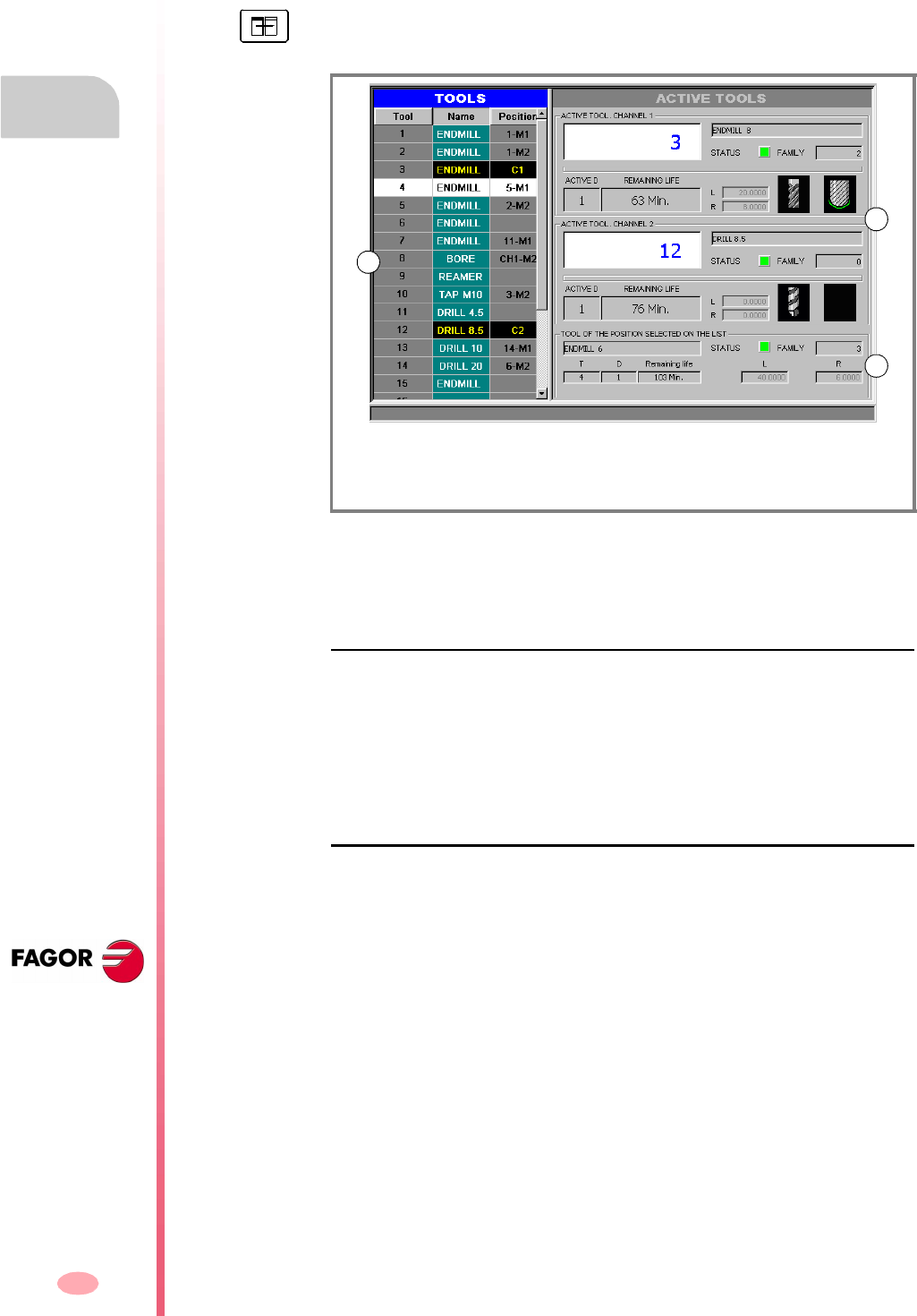
Operating manual
CNC 8070
9.
TOOL AND MAGAZINE TABLE
Active-tools table
(SOFT V03.0X)
190
9.4 Active-tools table
This table shows the list of available tools and which one is active in each channel.
The left panel shows the list of the available tools and the right panel shows the data
of the active tool in each channel.
Tool listing
For each tool, it indicates the position and the magazine where it is located, whether
it is a ground tool or the tool is active in a channel. The CNC updates data of the list
every time a tool change is carried out.
It is the same list that appears in the tool table. See "9.2.2 The tool list" on page 180.
Active tools
It shows the data of the active tool in each channel and also the data of the tool
selected on the list. It is also possible to change the tool of the spindle. See
"9.4.1 Changing the tool of the spindle" on page 191.
The tool data cannot be edited on this screen. The data shown here is defined in the
tool table.
The table is divided in two panels. To switch panels, press the panel-change key.
(A) Tool listing.
(B) Active tools.
(C) Tool selected on the list.
A
B
C

Operating manual
CNC 8070
TOOL AND MAGAZINE TABLE
Active-tools table
9.
(SOFT V03.0X)
191
9.4.1 Changing the tool of the spindle
It is possible to change the tool of the spindles from the active tools panel. The tool
to be placed must be defined in the tool table.
To change the active tool, follow these steps.
1. Use the cursor to select the active tool to be modified and enter the number of
the new tool.
2. Press the [CYCLE START] key to load the tool automatically or the [ENTER] key
to update the positions list after a manual tool change.
3. The tool list will show that the tool is in the spindle.
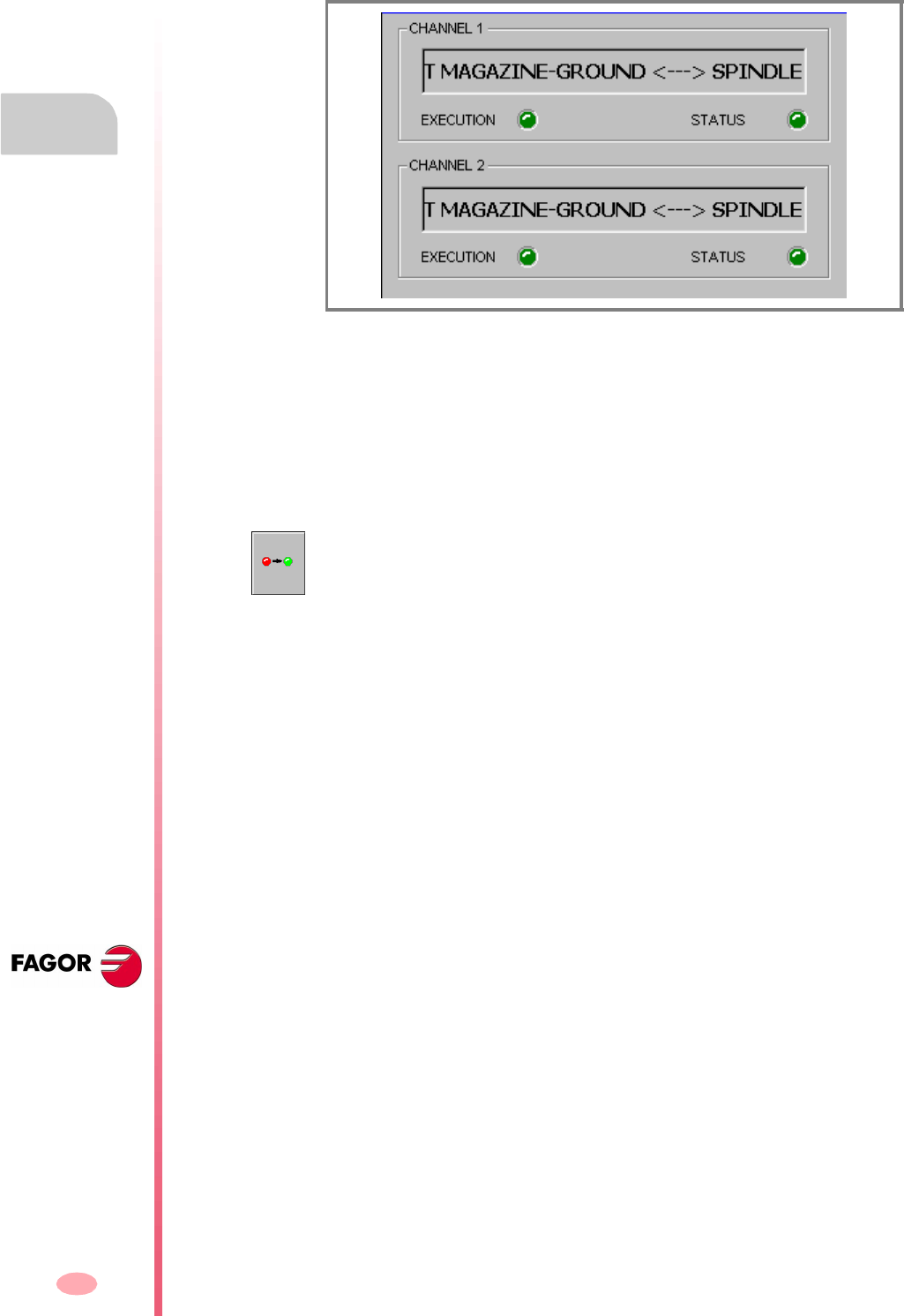
Operating manual
CNC 8070
9.
TOOL AND MAGAZINE TABLE
Table for the status of the tool change process
(SOFT V03.0X)
192
9.5 Table for the status of the tool change process
This screen monitors the tool changes being executed in each channel.
It indicates the following for each tool change process:
•The type of change selected and the magazine involved.
The type of change refers to the type of operation being carried out or to be carried
out when executing function M06. The possible types of change are load a tool
into the spindle or load and unload a ground tool from the magazine through the
spindle.
•The "execution " LED informs that the tool change process is running and that
the magazine is carrying out an operation.
•The "status" LED informs on whether the magazine is in an error state or not. To
eliminate the error condition, press the reset softkey in the magazine table.
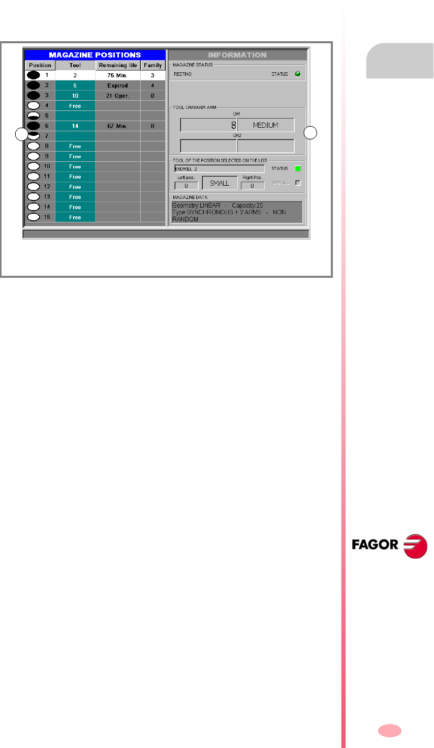
Operating manual
CNC 8070
TOOL AND MAGAZINE TABLE
Magazine table
9.
(SOFT V03.0X)
193
9.6 Magazine table
Up to four different magazines may be configured. Each magazine has a table
showing the tool distribution in the magazine and which table is in the spindle and
on each holder of the changer arm (if any).
The CNC updates the table data every time a tool is changed.
The table is divided in two panels.
The left panel shows the list of magazine positions. For each position, it indicates
whether it is free, disabled or has a tool. For each tool, it shows the remaining life time
(when using tool life monitoring) and the family it belongs to.
The right panel is informative only; it cannot be selected. This panel shows
information about the magazine status, about the tools in the tool changer arm and
about the tool selected on the list. Optionally, it may show information on the type and
configuration of the magazine.
(A) Magazine positions.
(B) Magazine information.
AB
Operating manual
CNC 8070
9.
TOOL AND MAGAZINE TABLE
Magazine table
(SOFT V03.0X)
194
9.6.1 Description of the icons of the vertical softkey menu
The options of the vertical menuof softkeys depend on which table is active.
The options shown for the tool table are.
The vertical softkey menu shows all the options for the selected table. The group of
options shown on this menu may be expanded with the softkey associated with the
"+" icon that offers a different set of options.
Load / unload a tool to / from the tool changer arm
(This icon is only available in magazines with tool changer arm).
It may be used to load and download a tool into the changer arm. See "9.7.2 Load
/ unload a tool to / from the tool changer arm" on page 201.
Find text
To search for a text on a tool list. See "9.1.2 Search for a text in the tables" on page
173.
Loading a tool into the magazine
The tool may be loaded into the magazine in two ways.
•Automatic loading (pressing [START]). A tool previously defined in the table is
loaded into the magazine. It is loaded from ground through the spindle.
•Manual loading (pressing [ENTER]). It assumes that the tool defined in the table
has already been manually loaded into the magazine. It updates the magazine
list.
See "9.7.1 Loading / unloading tools to / from the magazine" on page 199.
Unloading the tool from the magazine
The tool may be unloaded into the magazine in two ways.
•Automatic unload (pressing [START]). A tool defined in the table is unloaded from
the magazine. It is unloaded to ground through the spindle.
•Manual loading (pressing [ENTER]). It assumes that the tool defined in the table
has already been manually loaded from the magazine. It updates the magazine
list.
See "9.7.1 Loading / unloading tools to / from the magazine" on page 199.
Initializing the table
(The table can only be initialized when the CNC is "READY").
Initialize (reset) the magazine table. The CNC will request confirmation of the
command.
Initializing the tables eliminates all the tools from the list. It also initializes the active-
tools table because the tool arrangement in the magazine may have changed.
Save table
It saves the table data in a file. See "9.1.3 Save and load the tables" on page 174.
Operating manual
CNC 8070
TOOL AND MAGAZINE TABLE
Magazine table
9.
(SOFT V03.0X)
195
Recall table
It recalls the table data previously saved in a file. See "9.1.3 Save and load the
tables" on page 174.
Bear in mind that loading the magazine tool initializes the active-tools table.
Print table
It prints the contents of the table out to a printer connected to the CNC or as a file
(PRN format) at the CNC. See "9.1.4 Printing the tables" on page 176.
Enabling and disabling a magazine position
It enables or disables the magazine position selected with the cursor.
Resetting the magazine
It eliminates the error status of the tool manager. This icon is only available when
an error occurs at the tool manager.
Magazine information
It shows or hides the magazine data.

Operating manual
CNC 8070
9.
TOOL AND MAGAZINE TABLE
Magazine table
(SOFT V03.0X)
196
9.6.2 List of magazine positions
The list of magazine positions appears on the left panel of the tool magazine table.
For each position, it indicates whether it is free, disabled or has a tool. For each tool,
it shows the remaining life time (when using tool life monitoring) and the family it
belongs to.
Magazine position
The status of a position is indicated with a symbol next to the position number.
•The position is free (white filled circle).
•The position is semi-free (black-and-white filled circle).
•The position is occupied (black filled circle).
•The position is disabled (red filled circle).
Tool number
Number of the tool occupying the magazine position.
Remaining life
If the tool life monitoring is active, shows the remaining life, either in machining time
or in the number of operations to be carried out or the tool status (rejected or worn out).
Tool family
Family the tool belongs to, defined by the user in the tool table.
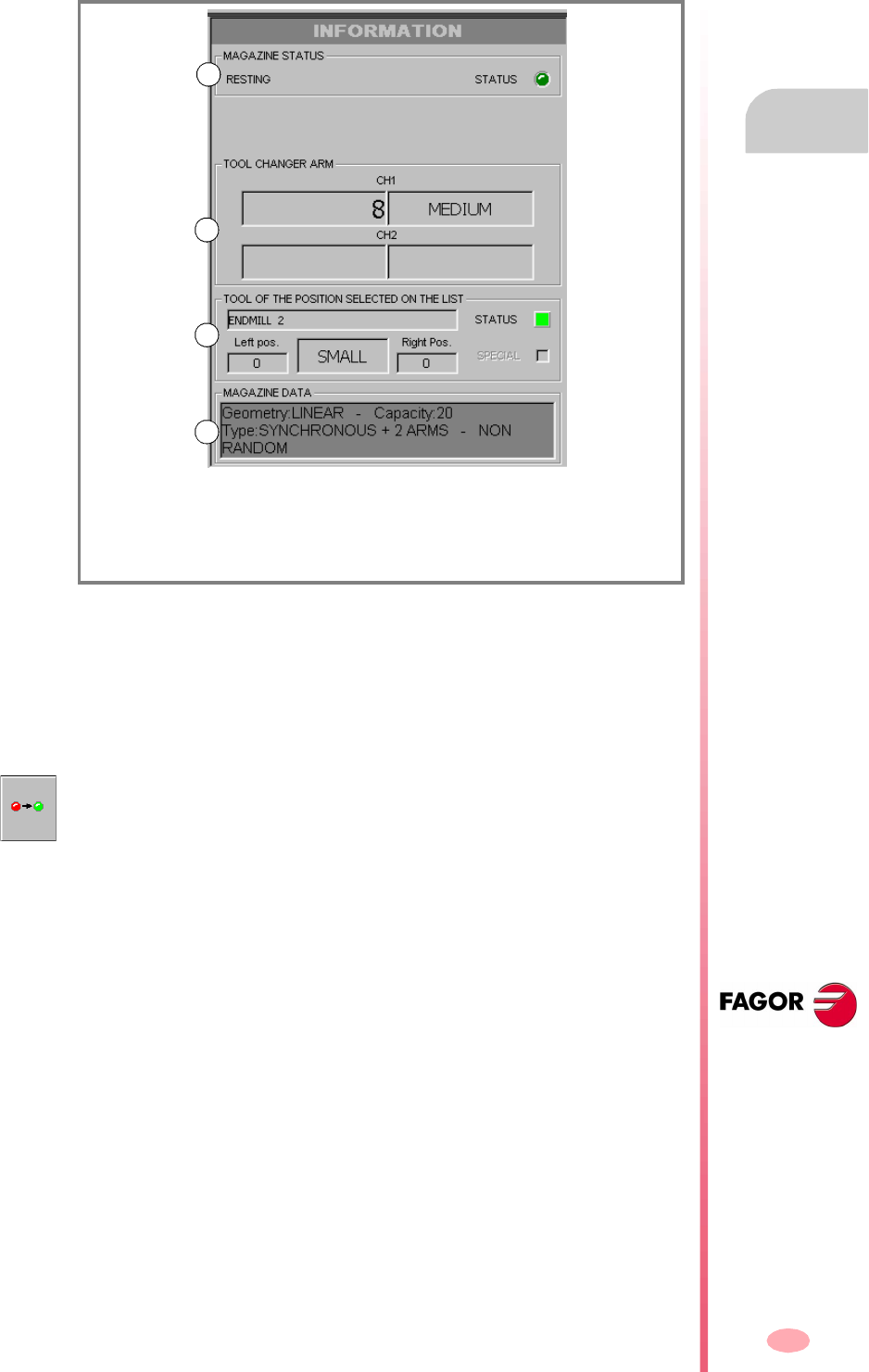
Operating manual
CNC 8070
TOOL AND MAGAZINE TABLE
Magazine table
9.
(SOFT V03.0X)
197
9.6.3 Magazine information
The right panel shows different information about the status of the tool magazine and
the tool changer arm. This information is grouped as follows:
Magazine status
This area shows the operation being carried out in the magazine.
In standby: The magazine is in standby.
Loading: A tool is being loaded into the magazine.
Unloading: A tool is being unloaded from the magazine.
Change status
If the magazine is involved in a tool change at a given time, it shows the information
about the status of that change; the operation is carried out when executing an M06,
manager status (in execution or at rest) and the status of the change process (whether
it is in error or not).
Tools in the changer arm
This area shows which are the tools that occupy each claw (holder) of the changer.
It shows the number and size of each tool.
(A) Magazine status.
(B) Tool in the claws of the changer arm.
(C) Tool selected on the list.
(D) Magazine data.
A
B
C
D
The "Status" led informs the user whether the magazine is in an error state or not.
To eliminate the error condition, press the reset softkey in the magazine table.

Operating manual
CNC 8070
9.
TOOL AND MAGAZINE TABLE
Magazine table
(SOFT V03.0X)
198
Tool information
It shows the data related to the magazine of the tool selected from the list. The "status"
led informs about the tool status.
Green The tool is available.
Yellow The tool life is about to expire.
Red The tool is expired (worn out) or has been rejected by the PLC.
Magazine data
Description of the type of magazine.
To show and hide this information, press the information softkey.
Operating manual
CNC 8070
TOOL AND MAGAZINE TABLE
Operations with the magazine table
9.
(SOFT V03.0X)
199
9.7 Operations with the magazine table
9.7.1 Loading / unloading tools to / from the magazine
The tools may be loaded and unloaded to/from the magazine manually or
automatically. When done manually, the positions list must be updated.
Manual load/unload
The operator places the tools directly in the magazine without using the CNC. Then,
the positions list must be updated.
Automatic load/unload
The operator places the tools in the spindle and the CNC places the tool in the
magazine. The positions list is updated automatically.
Initialize table
The table can only be initialized when the CNC is "READY". The table is initialized
from the vertical softkey menu.
Loading a tool
Depending on tool size, when it is loaded into the magazine, it may affect several
positions.
Magazine management using the "Load tool" softkey.
This type of management is valid for loading tools both automatically and manually.
After pressing the softkey, the user is asked what kind of loading to do.
1. Press the softkey associated with tool loading.
2. Enter the tool number and the magazine position to insert it. By default, it offers
the position selected on the list with the cursor.
3. Press the [CYCLE START] key to load the tool automatically by means of the
spindle or the [ENTER] key to update the positions list after loading manually.
Initializing the table eliminates all the data about the position of the tools
in the magazine. It also initializes the active-tools table because the tool
arrangement in the magazine has been changed.
The tool is loaded into the magazine using the vertical softkey menu. Only the tools
defined in the tool table may be loaded into the magazine and they must be defined
as ground tools. In other words, they must not be in any position of the magazine,
of the spindle or in the claws of the tool changer.
Even if the magazines are configured for not admitting ground tools while
machining, they may be loaded into the magazine through this maneuver.
i
Operating manual
CNC 8070
9.
TOOL AND MAGAZINE TABLE
Operations with the magazine table
(SOFT V03.0X)
200
Magazine management using the positions list.
This type of management is only valid for loading tools manually. It lets update the
list of positions after having placed the tools directly in the magazine, without using
the CNC.
1. Select a magazine position from the list and enter the number of the tool it
occupies it.
2. Press [ENTER] to update the positions list.
Unloading a tool
Magazine management using the "Unload tool" softkey.
This type of management is valid for unloading tools both automatically and manually.
After pressing the softkey, the user is asked what kind of loading to do.
1. Press the softkey associated with tool unloading.
2. Enter the number of the tool to be unloaded.
3. Press the [CYCLE START] key to unload the tool automatically to the spindle or
the [ENTER] key to update the positions list after unloading manually.
Magazine management using the positions list.
This type of management is only valid for unloading tools manually. It lets update the
list of positions after having removed the tools directly from the magazine, without
using the CNC.
1. Select a magazine position from the list and delete the number of the tool it
occupies it.
2. Press [ENTER] to update the positions list.
The tool is unloaded into the magazine using the vertical softkey menu. After
unloading a tool from the magazine, it becomes a ground tool.

Operating manual
CNC 8070
TOOL AND MAGAZINE TABLE
Operations with the magazine table
9.
(SOFT V03.0X)
201
9.7.2 Load / unload a tool to / from the tool changer arm
Nor can the tools that are in the holders of the tool changer arm be inserted in the
spindle.
To load or unload one of these tools:
1. Press the softkey associated with the operations with the changer arm.
2. Define the tool number in the positions of the tool changer arm.
When using a two-holder changer arm, there may not be tools in the spindle and
in the second holder of the changer arm at the same time.
3. Press [ENTER] to update the table.
A tool is loaded/unloaded to/from the claws (holders) of the changer arm using the
vertical softkey menu. To insert a tool in the holders of the changer arm (when
available), it must be placed in the magazine. Ground tools cannot be placed in the
claws (holders) of the tool changer arm.

Operating manual
CNC 8070
9.
TOOL AND MAGAZINE TABLE
Operations with the magazine table
(SOFT V03.0X)
202

203
CNC 8070
(SOFT V03.0X)
10
UTILITIES MODE
Utilities mode selection
Operations in this work mode
This work mode shows the files that may be accessed from the CNC and may be used
for the following operations:
•See the files stored at the CNC, in a floppy disk or at another CNC (or PC)
connected via Ethernet.
•Create new folders to save files.
•Select a file group and carry out operations such as copy, rename or delete files.
•Change file attributes.
•Do a file search based on a text already defined in them.
•Set a password to restrict the access to the customizing tool FGUIM, to machine
parameters and to the PLC.
•Make or restore a backup copy of the CNC data.
The utilities mode may be accessed from any other operating mode, even while a
program is in execution, by pressing the relevant key.

Operating manual
CNC 8070
10.
UTILITIES MODE
Appearance of the utilities mode
(SOFT V03.0X)
204
10.1 Appearance of the utilities mode
When this operating mode is active, it will be indicated at the top right side of the
general status bar. This mode only has one screen.
Standard configuration
The standard configuration of this work mode, described in this manual corresponds
to the one supplied by Fagor. In some cases, the manual shows a sample screen,
instead of that of the CNC in order to make it easier to understand.
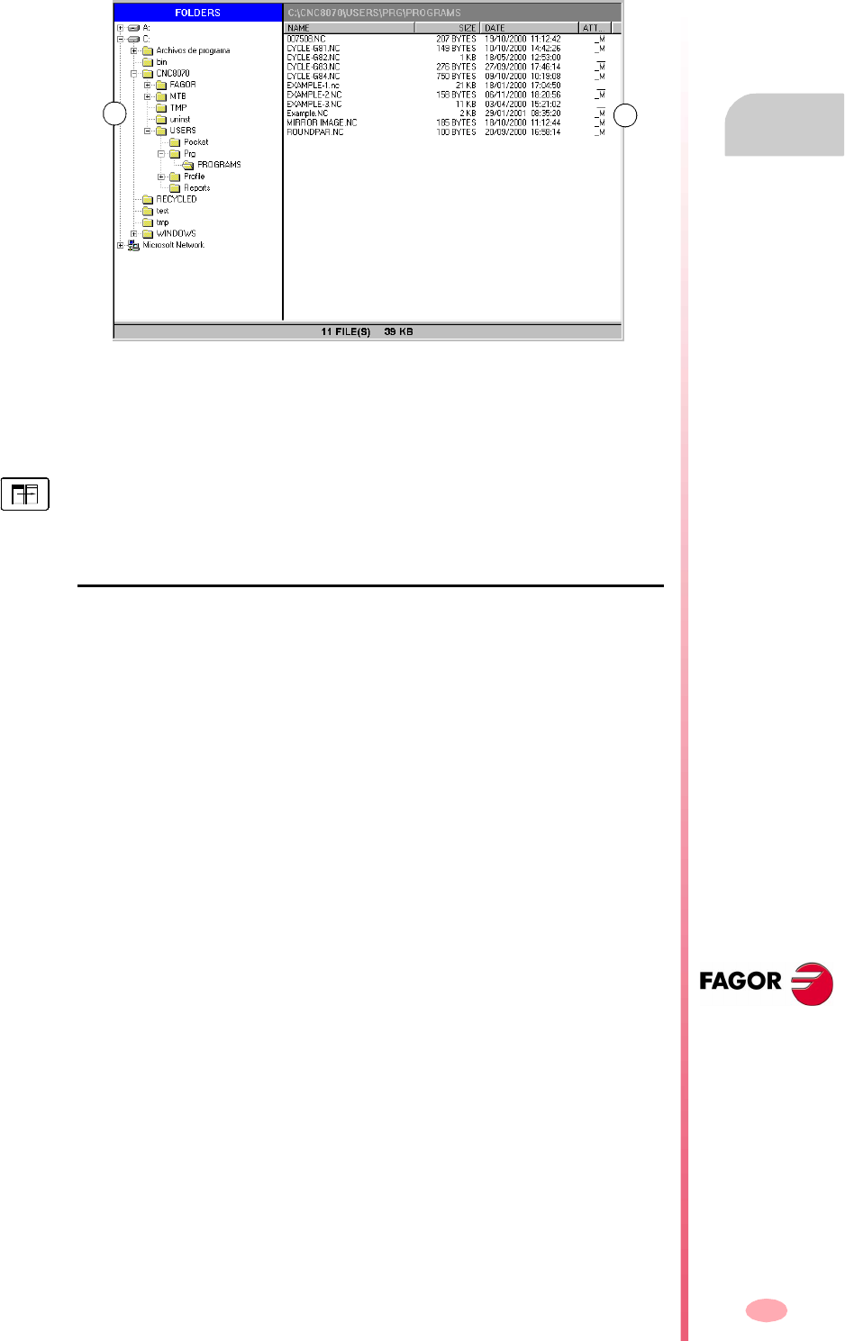
Operating manual
CNC 8070
UTILITIES MODE
Appearance of the utilities mode
10.
(SOFT V03.0X)
205
10.1.1 Screen description
The utilities mode screen shows the following information:
A. Folder tree.
It may show the folders of the CNC, of a floppy disk or another CNC (or PC)
connected via Ethernet.
B. List of files saved in the selected folder.
Softkey menu
When selecting the utilities mode, the horizontal softkey menu will show the options
related to this work mode.
AB
To switch windows, press the relevant key.
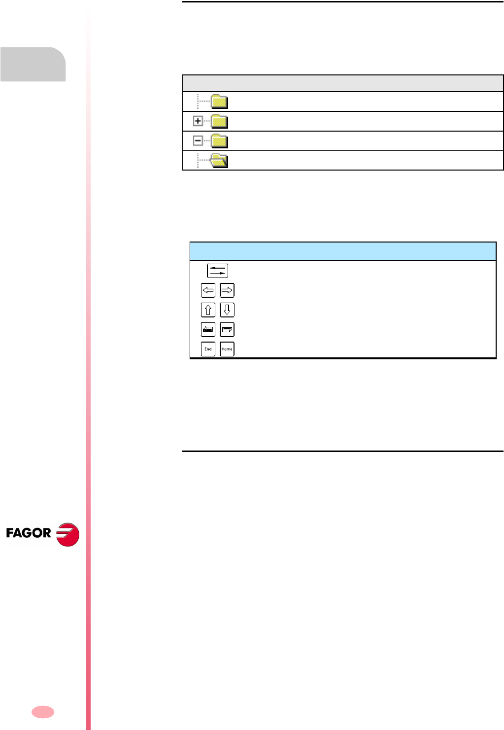
Operating manual
CNC 8070
10.
UTILITIES MODE
Appearance of the utilities mode
(SOFT V03.0X)
206
10.1.2 Window description
Folder tree
This window shows the folders that may be accessed from the CNC, as well their
structure. Besides the CNC folders, it may show those of a floppy disk or another CNC
(or PC) connected via Ethernet.
The folders may contain files and other folders.
To select a folder from the list:
•Move the cursor with the relevant keys.
•Using the alphanumeric keyboard, pressing a key will select the first element
starting with that letter. Pressing it again will select the second one and so on.
When selecting a folder, the CNC shows a list of the files it contains (See the
"10.2.2 Options" section of this chapter). Likewise, the bottom of the window will
show the number of files contained in the folder and the total size (bytes) they amount
to.
List of files
This window shows the files stored in the selected folder. Any of them may be deleted,
renamed, its protections changed and copied within the same device (CNC, PC,
floppy disk) or between two different devices.
This window offers the following information:
•The file name.
•The file size, in bytes.
•The time and date when the file was edited last.
•The attributes of the file.
Icon Description
It contains no folders.
It contains no folders and they are not shown here.
It contains folders and they are shown here.
The folder has been selected.
Keys to select a folder
To switch windows (folders or files).
To close and open a folder submenu.
To move the cursor thru the elements of the window.
To move the cursor page by page.
To move the cursor to the beginning or end of the list.
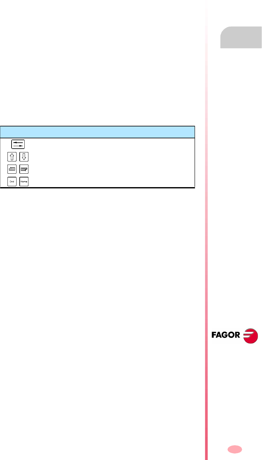
Operating manual
CNC 8070
UTILITIES MODE
Appearance of the utilities mode
10.
(SOFT V03.0X)
207
Attributes. Modifiable and hidden files
Only the letters of the attributes currently selected will be shown. Those not selected
will appear as "_" .
Select files from the list
To copy, rename, delete, etc. the files must be previously selected on the list. A file
may be selected from the list:
•Move the cursor with the relevant keys.
•Using the alphanumeric keyboard, pressing a key will select the first element
starting with that letter. Pressing it again will select the second one and so on.
•Using the "file search" option of the softkey menu permits looking for all the files
that contain the indicated text.
To select a group of files, keep the [SHIFT] key pressed while the moving the cursor.
To add or remove a file from the selection, keep the [CTRL] key pressed and place
the cursor on the file and press [SPACE] key.
H The file is hidden and it will not appear when selecting a program for editing
or execution.
Remember that a hidden file can still be deleted if its name is known. To
prevent that (if so wished) its "modifiable" attribute should be removed.
M The file may be modified; in other words, edited, copied, deleted, etc.
Keys to select a folder
To switch windows (folders or files).
To move the cursor thru the elements of the window.
To move the cursor page by page.
To move the cursor to the beginning or end of the list.
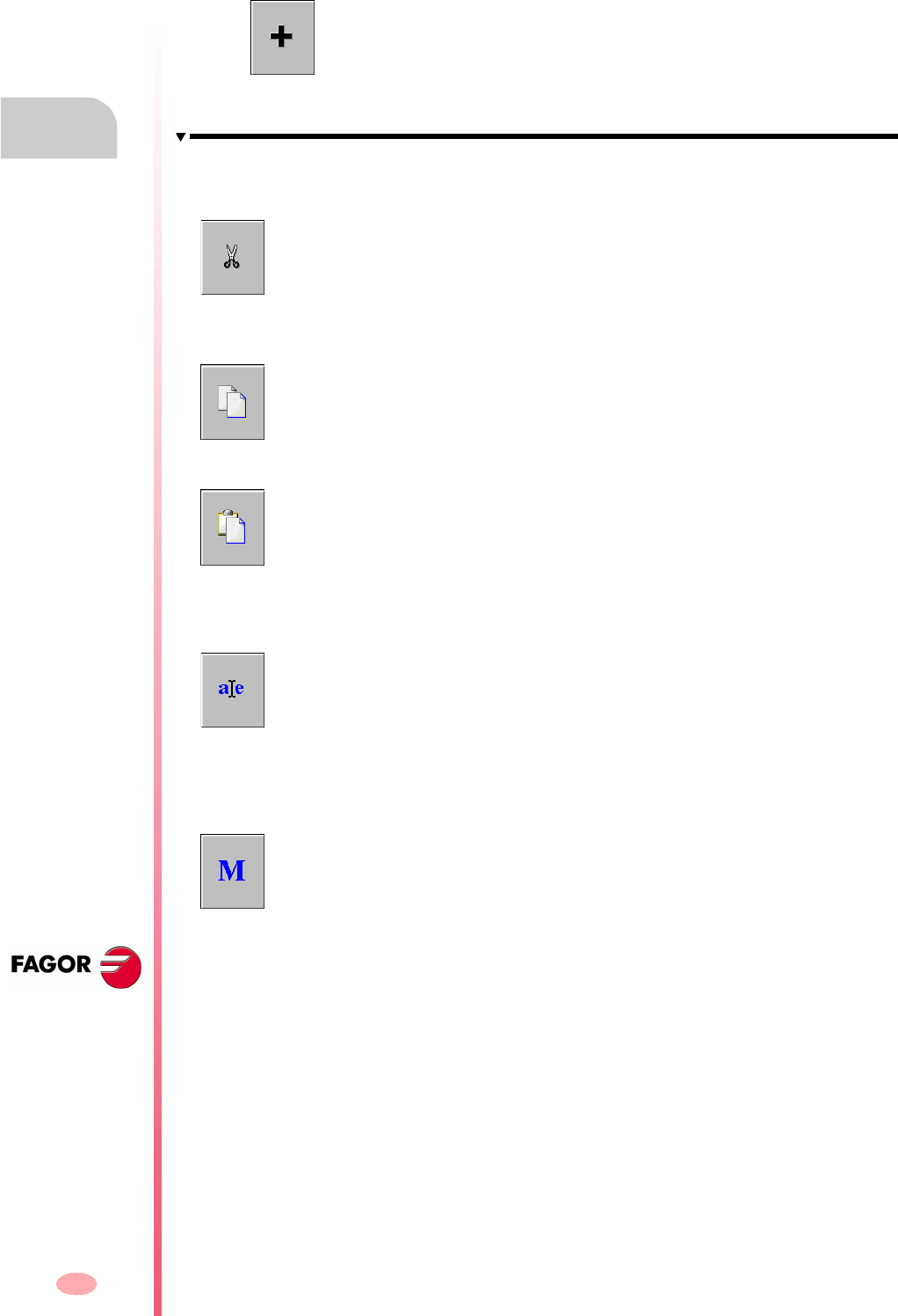
Operating manual
CNC 8070
10.
UTILITIES MODE
Appearance of the utilities mode
(SOFT V03.0X)
208
10.1.3 Vertical softkey menu (icons)
List of icons
The icon menu always shows all the icons related to the Utilities mode. The
group of icons of this menu may be expanded with the softkey associated with
the "+" icon that offers a new set of icons.
Cut
Copies the selected files on the clipboard. After pasting the content of the clipboard,
the files are deleted from the folder.
(This icon is only available when there is a file selected).
Copy
Copies the selected files on the clipboard.
(This icon is only available when there is a file selected).
Paste
Pastes the files from the clipboard into the selected folder. If the files were placed
using the "Cut" option, they will be removed from their original location.
The contents of the clipboard are not eliminated after "pasting". Therefore, this
pasting operation may be repeated as often as you wish.
Rename
It is used to change the name of the folder or file currently selected.
•When renaming a folder, if there is one already with the new name, the proposed
name change will be ignored and the folder will keep its original name.
•If when renaming a file, there is a previous file with the same name in the folder,
the new file replaces the previous one.
Modifiable file
It is used to change the "modifiable" attribute of the selected files. This attribute allows
protecting the files so they cannot be modified in the editing mode.
The attributes column shows the letter -M- indicating that the program may be
modified.
When a program is NOT modifiable, its contents may be viewed; but cannot be
modified.
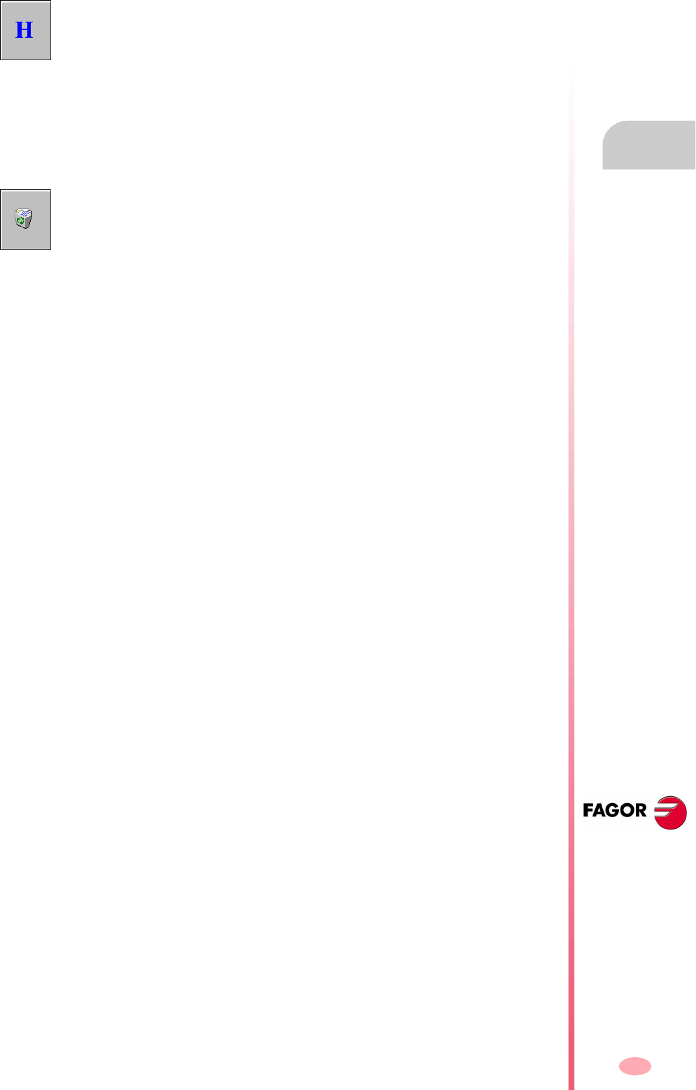
Operating manual
CNC 8070
UTILITIES MODE
Appearance of the utilities mode
10.
(SOFT V03.0X)
209
Hidden file
It is used to changed the "hidden" attribute of the selected files. This attribute allows
protecting the files so they are not displayed when selecting a program to be edited
or executed.
The attributes column shows the letter -H- indicating that the program will be hidden
(not visible).
However, a hidden program may be deleted if its number is known; therefore, it is
recommended to remove the modifiable attribute (M) in order to avoid deleting it.
Remove file
It is used for deleting the selected folder or files.
To delete the files, the CNC will show a dialog box requesting confirmation of the
command whereas the empty folders will be deleted directly without requesting
confirmation.
The folders can only be deleted if they are empty.

Operating manual
CNC 8070
10.
UTILITIES MODE
Utilities (Softkeys)
(SOFT V03.0X)
210
10.2 Utilities (Softkeys)
10.2.1 Sorted by
It is used to order the list of files.
The file list may be ordered alphabetically, by size, by data or by type. When pressing
the same ordering criteria twice, the CNC toggles from ascending to descending and
vice versa.
The softkey menu shows the ordering criteria currently selected (the softkey will
appear pressed).
10.2.2 Options
It is used to personalize how the program listing will be displayed on the screen.
Update
It updates the list of files showing the files of the folder currently selected. Only when
the "auto-update" option is not active.
Auto-update
When this option is selected (the softkey will appear pressed), every time a folder is
selected, the CNC will automatically update the list of files.
Column adjust
When this option is selected (the softkey will appear pressed), the columns of the file
lists will adjust to the text they contain so as to show the text that may be truncated
because it is too long.
Reset all
It closes the folder tree (layout) and it only shows the devices (floppy disk, Ethernet
network, etc. ) connected to the CNC.
Show hidden files
When this option is selected (the softkey will appear pressed), the file list shows all
the files of the selected folder even those having the "hidden" attributes. Otherwise,
these files will not be shown.
When selecting this option, the softkey menu shows the different ordering options.
To return to the previous menu, press the key for the previous menu.
When selecting this option, the softkey menu shows the following personalizing
options. To return to the previous menu, press the key for the previous menu.
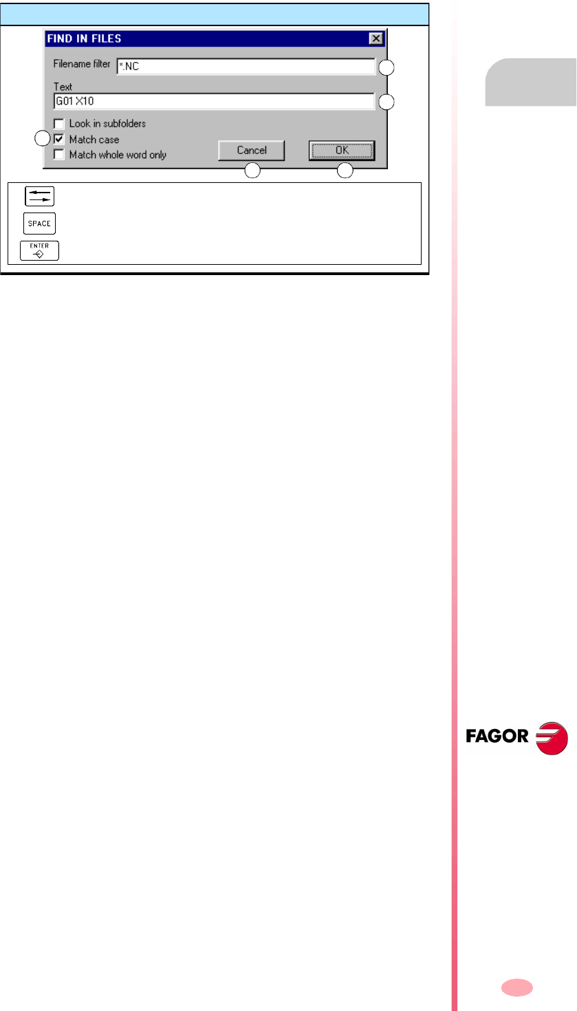
Operating manual
CNC 8070
UTILITIES MODE
Utilities (Softkeys)
10.
(SOFT V03.0X)
211
10.2.3 Search in files
It is used to search files. When selecting this option, the CNC shows a dialog box
where the following data may be defined:
A. Description of the files to be searched. The "*" and "?" wild characters may be
used on the search, meaning:
In such a way that:
B. Text included within the files.
C. Defines the search criteria.
•Look in the sub-folders.
•Ignore uppercase and lowercase.
•Consider the text to find as a whole word.
D. Start the defined search.
E. Cancel the defined search.
After defining the search options, place the cursor on one of the lower buttons to
accept (D) or cancel (E) the defined search and press [ENTER].
The file window will show the list of the programs found.
* Any character string.
? Any character.
* Looks for all the files.
*.NC Looks for all the files having the extension "NC".
exa*.* Looks for all the files beginning with "exa".
Find in file
To move the cursor through the elements of the list.
To activate/deactivate the selection box (C).
To start or cancel the defined search.
A
B
C
D E
Operating manual
CNC 8070
10.
UTILITIES MODE
Utilities (Softkeys)
(SOFT V03.0X)
212
10.2.4 Select all
It selects all the files of the list. The selection will be canceled by moving the cursor.
To add or remove a file from the selection, keep the [CTRL] key pressed and place
the cursor on the file and press [SPACE] key.
Having selected a group of files, they may be deleted, copied, cut or their attributes
may be changed by pressing the relevant icon.
10.2.5 Invert selection
It inverts the file selection made selecting the files that appeared unselected and vice
versa.
To add or remove a file from the selection, keep the [CTRL]
key pressed and place
the cursor on the file and press [SPACE] key.
Having selected a group of files, they may be deleted, copied, cut or their attributes
may be changed by pressing the relevant icon.
10.2.6 New folder
It is used to create a new folder to store files.
When selecting this option, the CNC shows a dialog box requesting the file name.
Write the new name and select one of the buttons to accept it or ignore it.
If when defining the folder name, there is already a folder with the same name, it will
NOT create the new folder.
Keys to select a folder
To move the cursor thru the elements of the window.
To move the cursor page by page.
To move the cursor to the beginning or end of the list.
Keys to select a folder
To move the cursor thru the elements of the window.
To move the cursor page by page.
To move the cursor to the beginning or end of the list.
Keys to select a folder
To move the cursor through the elements of the list.
To confirm the option selected with the cursor.

Operating manual
CNC 8070
UTILITIES MODE
Utilities (Softkeys)
10.
(SOFT V03.0X)
213
10.2.7 Protection passwords
The passwords may be used to define each of the codes that the user will have to
enter in order to access certain CNC functions. If entered correctly, it stores it and
it does not request it again unless the CNC is turned off. If the password is wrong,
the requested action cannot be carried out and it requests it again every time.
Press the "Passwords" softkey to access the password setting screen. The following
passwords may be defined.
•General password.
•PLC.
•Machine parameters.
•Customizing.
•Machine parameters for kinetics.
General password
It is requested when trying to access this password setting screen.
PLC
It is requested when trying to carry out the following actions at the PLC:
•Editing the PLC program. When entering the wrong password, the PLC program
opens as read-only.
•Adding a file to the project.
•Deleting a file.
•Renaming a file.
•Editing PLC messages. When entering the wrong password, the PLC messages
may be neither displayed nor edited.
•Generate PLC.
•When accessing to the "Commands" service options.
•In monitoring, when modifying the status of a resource.
Machine parameters
It is requested when trying to carry out the following actions in the machine parameter
table:
•Modifying the value of a parameter.
•Initialize a table.
•Loading a table.
Customizing
It is requested when entering the FGUIM application. When entering the wrong
password, it will not be possible to access the application.
Operating manual
CNC 8070
10.
UTILITIES MODE
Utilities (Softkeys)
(SOFT V03.0X)
214
Machine parameters for kinetics
It is requested when trying to carry out the following actions in the machine parameter
tables for the kinematics: If not set, it will apply the password used in the rest of the
machine parameters.
•Modifying the value of a parameter.
•Initialize a table.
•Loading a table.
How to set the protection passwords
Press the "Passwords" softkey to access the password setting screen. From this
screen, it is possible to define, modify or delete the passwords. If this screen is
protected, pressing the softkey will request the general password.
Each password may be up to 10 ASCII characters long. It is case sensitive.
The "Delete all" softkey deletes all the passwords defined.
Keys to set the password
To select the previous or next password.
It assumes the defined password.
To cancel the defined password.
It deletes the selected password.

Operating manual
CNC 8070
UTILITIES MODE
Utilities (Softkeys)
10.
(SOFT V03.0X)
215
10.2.8 Data safety backup. Backup - Restore
This option may be used to make a backup copy of the data of the MTB folder in order
to be able to restore this configuration later on if necessary. The backup is saved in
a single file.
Both the folder being backed up and the file name it is saved in may be configured.
When not indicated otherwise, it makes a backup of the "MTB" folder and it saves
it in the mtb.r file in unit –A:–.
Configuring backup options
The backup options may be defined using the "Backup options" softkey. As backup
options, it is possible to define both the folder being backed up and the name of the
file containing the data. By default, it makes a backup of the "MTB" folder and it saves
it in the mtb.r file in unit –A:–.
The CNC saves the defined options in a file called backup.ini. If this file does not exist
when making or restoring a backup, the default values will be used.
Making a data backup
The backup is made using the "automatic backup" softkey. Pressing this softkey
makes a safety copy of the data of the indicated folder. The data is saved in the
selected file.
When not indicated otherwise or if the backup.ini file does not exist, it will make a
backup of the "MTB" folder and will save it in the mtb.r file in unit –A:–
Restoring data from a backup file
Backup data is restored using the "Restore backup" softkey. Pressing this key copes
the data from the indicated file to its original folder; i. E. To the folder that was backed
up. If this folder does not exist, it creates it and goes on with the operation.
If the files being restored already exist, they will be overwritten; i.e. the ones in the
folder will be replaced by the ones in the backup.
The name of the file from which the backup is restored is defined in the backup.ini
file. If this file does not exist, it proceeds as follows:
1. It looks for the mtb.r file in unit –A:– and it restores it.
2. If this file does not exist, it restores the first backup file (extension –r–) of unit –A:–
3. If there is no backup file, it shows the relevant error message.

Operating manual
CNC 8070
10.
UTILITIES MODE
Utilities (Softkeys)
(SOFT V03.0X)
216
217
8070 CNC
(SOFT V03.0X)
11
PLC
In this operating mode, the PLC may be accessed to check its operation or the status
of the different PLC variables. It is also possible to edit and analyze the PLC program
as well as the message and error files of the PLC.
MDI mode selection
What can you do in this work mode?
In short, the PLC mode offers the following operations:
•Edit, modify or view the contents of the PLC project.
•Debug the PLC program by executing the different parts of the program separately
(first cycle, main module, periodic module).
•Analyze the behavior of the logic signals of the PLC program depending on a time
base and triggering conditions set by the user.
•Monitor the status of PLC resources and variables.
•See all the resources used in the PLC project and in which program of the project
they are being used.
•Run statistics on execution times of the PLC project and of the modules that form
it.
•Edit, modify or view the texts associated with the messages and errors of the PLC.
The PLC mode may be accessed either using the user key customized for it or from
the tasks window. The task window may be accessed with key combination
[CTRL]+[A].
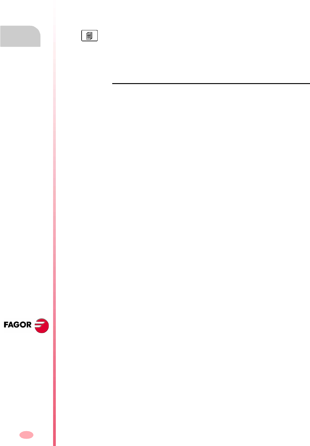
Operation manual
8070 CNC
11.
PLC
Appearance of the PLC mode
(SOFT V03.0X)
218
11.1 Appearance of the PLC mode
When this operating mode is active, it will be indicated at the top right side of the
general status bar.
This operating mode may be displayed with several screens. Each of them
corresponds to a PLC service. The exchange between the different services is carried
out with the list of services.
Standard configuration
The standard configuration of this work mode, described in this manual corresponds
to the one supplied by Fagor. In some cases, the manual shows a sample screen,
instead of that of the CNC in order to make it easier to understand.
The different services overlap each other. If several services active, it is possible to
switch from one to another using the relevant key, if it has been set accordingly. The
services are switched in a rotary manner, in such a way that when pressing on the
last active service, it shows the first one.
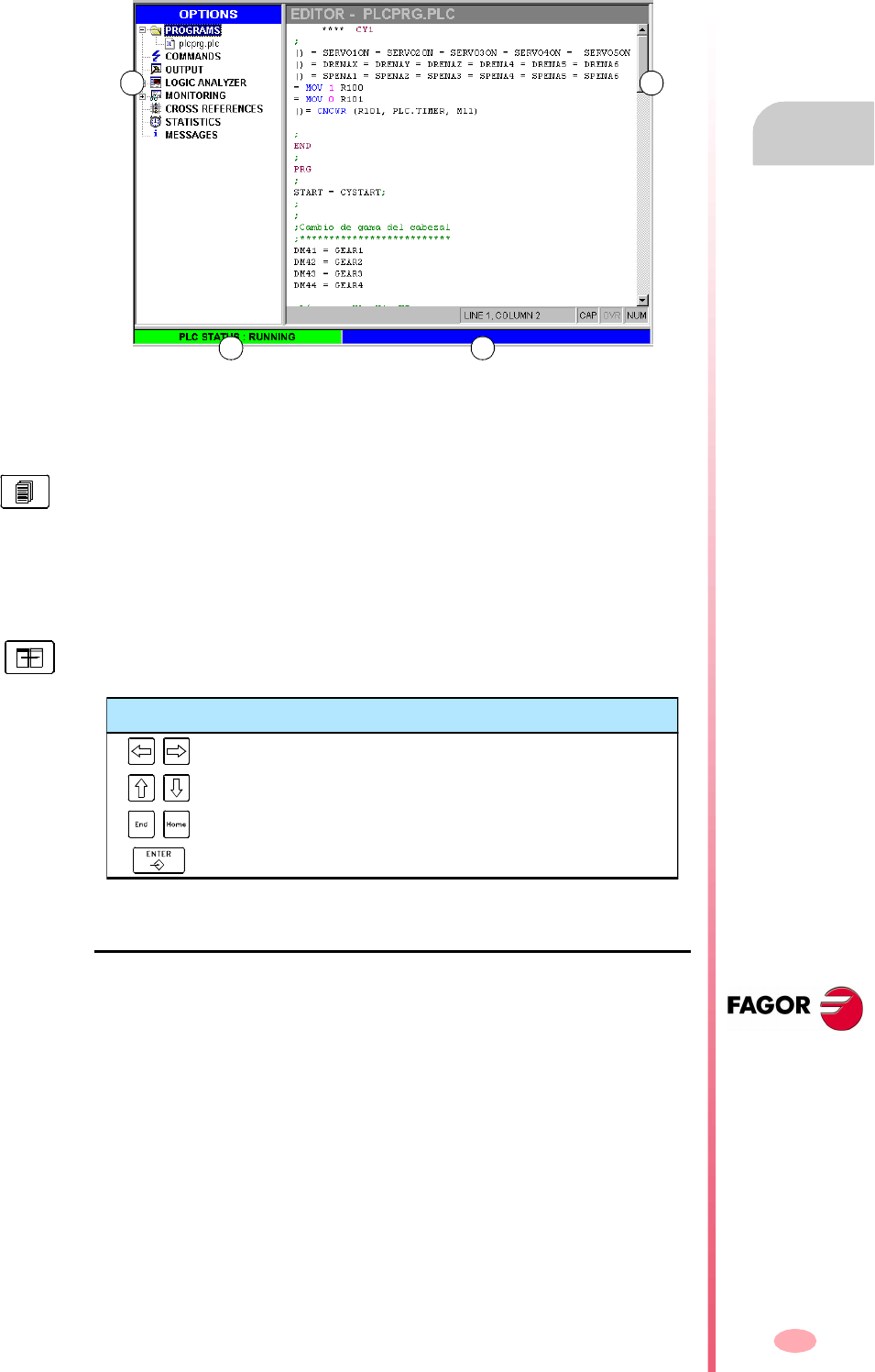
Operation manual
8070 CNC
PLC
Appearance of the PLC mode
11.
(SOFT V03.0X)
219
11.1.1 Screen description
The PLC mode screen shows the following information.
A. Service window.
It shows a list of the services available in the PLC environment.
B. Data window.
C. It shows the PLC status, running or stopped.
D. CNC messages.
Softkey menu
When selecting the PLC mode, the horizontal softkey menu will show the options
associated with the PLC service currently selected. The set of options offered by this
menu may be changed using the "+" softkey which offers a new set of options.
A B
C D
It shows the screen associated with the selected service, if any. The screens of
the different services overlap each other. If several services active, it is possible
to switch from one to another using the change key, if it has been set accordingly.
To close a screen, press [ESC].
To switch windows, press the relevant key.
Keys for selecting a service
To close and open the file list of a service.
To move the cursor thru the services of the window.
To move the cursor to the beginning or end of the list.
To acces the service selected with the cursor.
Operation manual
8070 CNC
11.
PLC
Appearance of the PLC mode
(SOFT V03.0X)
220
11.1.2 Icon description (vertical softkeys)
The icon menu always shows all the icons associated with the active PLC service.
The icons are activated with their associated softkey (F8 to F12).
List of icons
Show/hide the service window
It toggles between the shared usage of the area of the PLC environment (that displays
both the service window and the data window) and the full work screen (hiding the
service window so the data window is expanded covering the whole area of the PLC
environment).
Find text
It is used for searching a text in all the files of the project. The result will be shown
at the "Outputs" service.
Go to file
(It only appears when working with the "Outputs" or "Cross references" service).
If the cursor is positioned on the result of a text search, a compiling error or a PLC
resource, after selecting this option, it opens the corresponding file and the cursor
goes to the line it refers to.
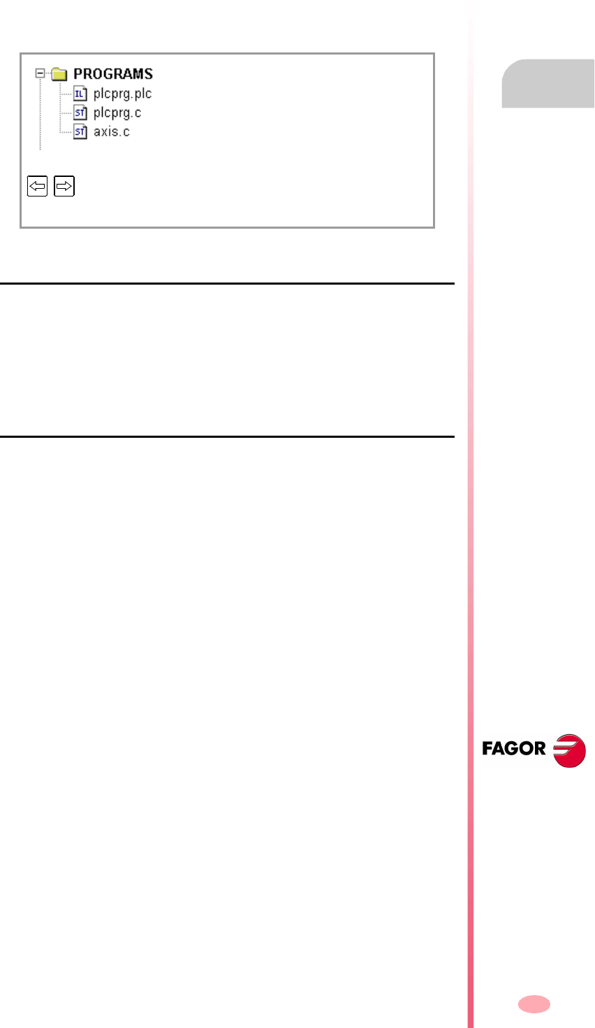
Operation manual
8070 CNC
PLC
"Programs" service
11.
(SOFT V03.0X)
221
11.2 "Programs" service
This service is used for managing the PLC project and its files. The PLC project may
consist of several files edited in any of the following languages:
•Equations or mnemonics (extension *.PLC).
•C language (extension *.C).
PLC project
The PLC project is a set of files that, once compiled, generate the PLC program.
When selecting the PLC project, the softkey menu will show the options to manage
that project. Among these options, it is possible to add files to the PLC project and
compile it.
Files of the PLC project
As mentioned earlier, the PLC project may consist of one or several files edited in
one of the following languages:
•Equations or mnemonics.
•C language.
One of the files of the PLC project may be edited in mnemonic languages (extension
*.PLC). The rest must be edited in "C" language (extension *.C).
When selecting a file, the softkey menu shows the options to manage that file. Among
these options, it is possible to edit and monitor the file. These options will show the
editing and monitoring screens.
PLC project
Files making up the PLC project
Selecting the PLC project, it shows or hides the list of its files.
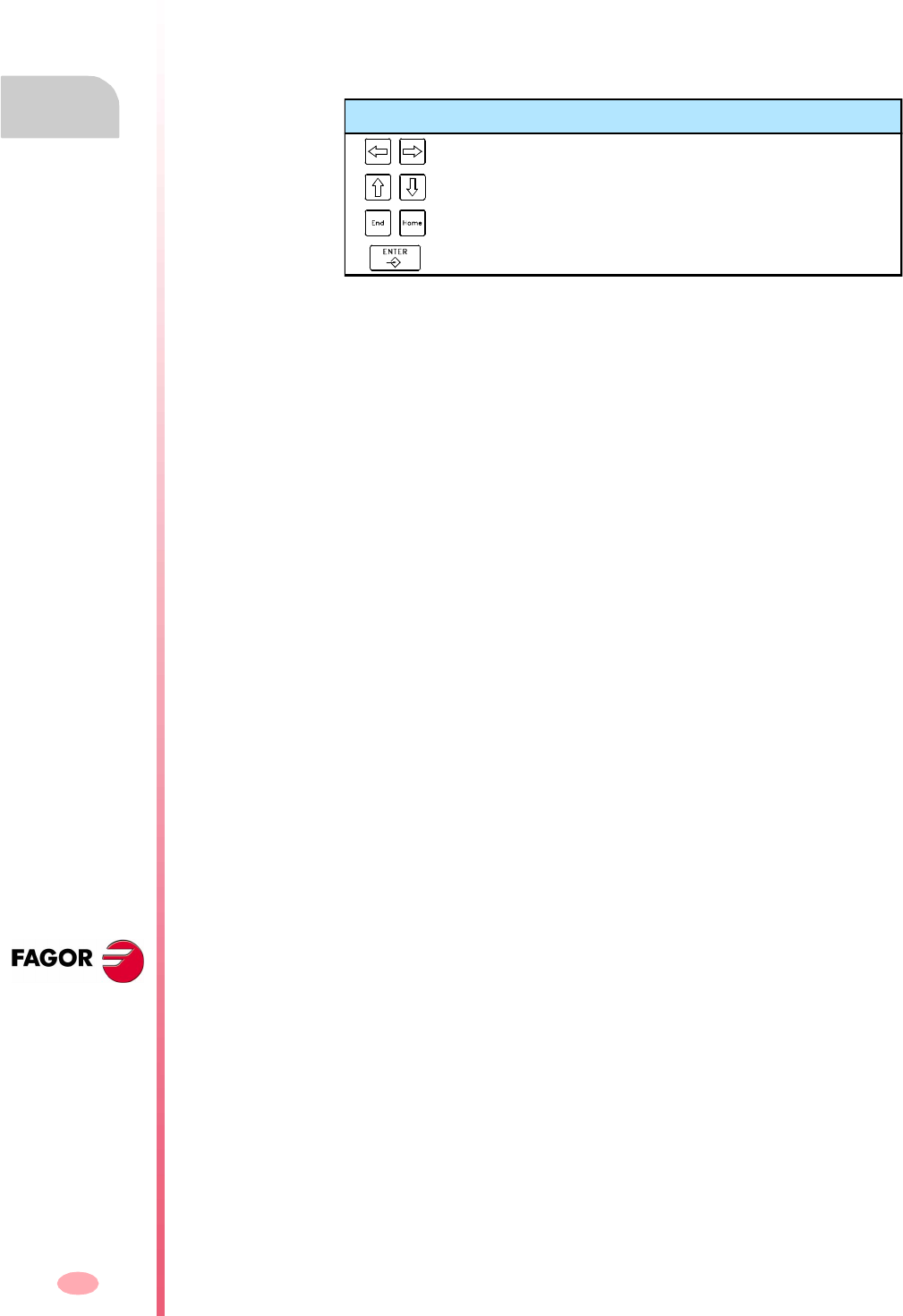
Operation manual
8070 CNC
11.
PLC
"Programs" service
(SOFT V03.0X)
222
11.2.1 PLC project (softkeys)
These options are used to create a PLC project and compile it to create the executable
PLC program.
PLC project "Add file"
It is used to add a file to the PLC project. This file may be a new one or an existing
one. When selecting this option, the CNC shows a list of the available files.
To add a file to the PLC project.
1. Select the file from the list or write its name in the bottom window.
2. Press [ENTER] to accept the selection and add the file or [ESC] to cancel the
selection and close the file listing.
When accepting the selection, the selected file will appear on the list that make up
the PLC project.
PLC project "Generate PLC"
It compiles and loads the PLC program based on the files that make up the PLC
project. If an error occurs during compilation, the program will not be generated and
the CNC will display a list of the detected errors.
Keys for selecting a service
To switch windows.
To move the cursor through the elements of the list.
To add the selected file.
To cancel the selection and close the program listing.
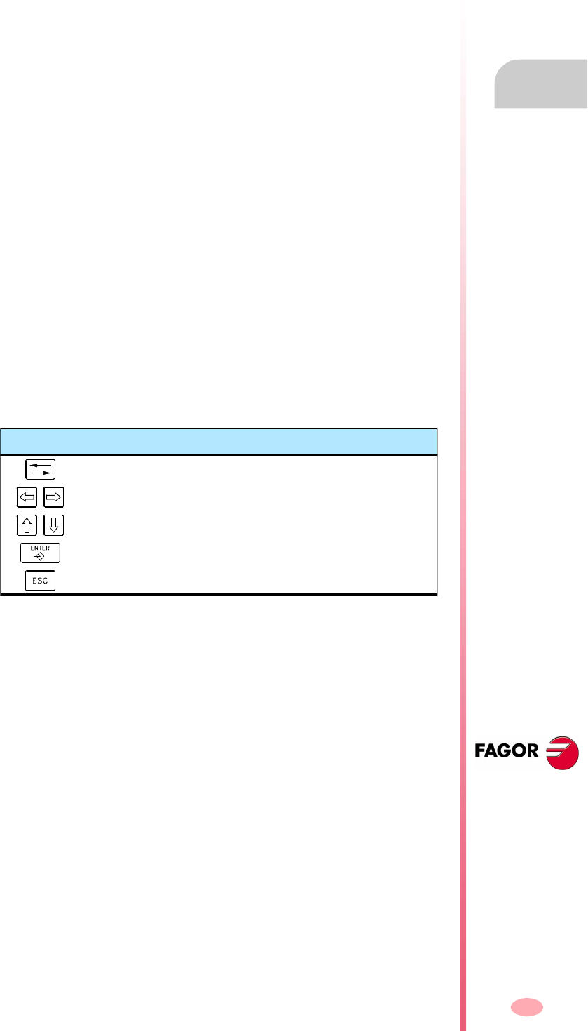
Operation manual
8070 CNC
PLC
"Programs" service
11.
(SOFT V03.0X)
223
11.2.2 Files of the PLC project PLC (Softkey)
When selecting a program of the PLC project at the service window, the softkey menu
will offers the following options.
Files of the PLC project "Edit"
It is used to edit the selected PLC file.
Selecting this option access the editing window (section on "11.3 Program editing"
in this chapter).
Files of the PLC project "Monitoring"
It is used to monitor the selected PLC file.
Selecting this option access the monitoring window (section on "11.5 Program
monitoring" in this chapter).
Files of the PLC project "Eliminate"
It deletes the selected file of the PLC project (the file will still be available in the CNC's
hard disk).
Files of the PLC project "Rename"
It is used to change the name of the selected file.
Files of the PLC project "Copy"
It is used to make a copy of the selected file.
When selecting this option, the CNC shows a list with the programs stored at the CNC.
To make a copy of the file:
1. Select the destination folder for the copy.
2. Define the file name at the bottom window. To replace an existing file, select it from
the list.
3. Press [ENTER] to copy the file or [ESC] to cancel the selection and close the file
listing.
Keys for selecting a service
To switch windows.
To close and open a folder submenu.
To move the cursor thru the elements of the window.
To save the new program.
To cancel the selection and close the programs listing.
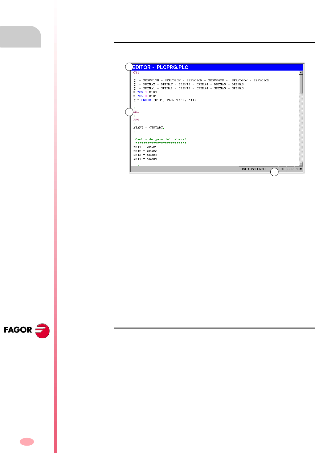
Operation manual
8070 CNC
11.
PLC
Program editing
(SOFT V03.0X)
224
11.3 Program editing
To edit a program, select it at the service window and select the "Edit" option of the
softkey menu. The CNC will access the program editor and will show the contents
of the selected program.
To close the edit window, press [ESC].
Editor description
The editing window shows the following information:
A. Title bar.
Name of the program selected for editing. An "*" next to the program name means
that the changes made to the program have not been saved (the program must
be saved so they do not get lost).
B. Edit area.
Program editing area showing its contents.
C. Status bar.
Information about cursor position and the status of the editor options such as:
Softkey menu
When accessing the PLC program editor, the horizontal softkey menu will show all
the options associated with editing a file.
CAP Capital letters. When active, the text is always written in capital
letters.
OVR Overwrite text. It toggles between overwriting and inserting text.
When active, it overwrites the existing text.
NUM Numeric keypad active.
A
B
C

Operation manual
8070 CNC
PLC
Program editing (softkeys)
11.
(SOFT V03.0X)
225
11.4 Program editing (softkeys)
11.4.1 Analyze
It analyzes the program searching for errors. The errors found will be displayed in the
"Outputs" service window.
11.4.2 File
It is used to restore, save, import or print a file.
File "Restore original"
This option will only be available when the "auto-save" option is active (the section
on "11.4.6 Customizing" in this chapter).
It is used to recover the original file without the changes made since the last time it
was opened. When selecting this option, the CNC requests confirmation of the
command.
File "Save"
This option will only be available when the "manual-save" option is active (the section
on "11.4.6 Customizing" in this chapter).
It is used for saving the file that is being edited.
File "Save as"
It is used to save the file, that is being edited, with a different name. After saving the
file, one keeps editing the new file.
File "Include program"
It is used to import the contents of a file saved at the CNC into the program that is
being edited.
File "Print"
It is used to print the file, that is being edited, out to a printer connected to the CNC.
To close this window and return to the editor, press [ESC]. To return to the editor
without closing the window, press the screen switching key.
When selecting this option, the softkey menu shows the available options. To return
to the main menu, press the key for the previous menu.

Operation manual
8070 CNC
11.
PLC
Program editing (softkeys)
(SOFT V03.0X)
226
11.4.3 Undo
To "undo" the last modifications made. The modifications are undone one by one
starting from the most recent one.
11.4.4 Operations with blocks
It is used to copy, cut and paste the information of a block or set of blocks and export
this information as an independent program.
This option is only available when there is a text selected in the program or on the
clipboard. To select a text in the program, keep the [SHIFT] key pressed while moving
the cursor.
Operations with blocks "Copy"
It copies the selected text onto the clipboard.
Operations with blocks "Cut"
Copies the selected text onto the clipboard and deletes it from the program.
Operations with blocks "Paste"
Pastes the contents of the clipboard into the program.
Operations with blocks "Copy to program"
Saves the selected texts as an independent program.
When selecting this option, the CNC shows a list of the available programs. To save
the text as a program:
1. Select the destination folder.
2. Define the file name at the bottom window. To replace an existing file, select it from
the list.
3. Press [ENTER] to save the program or [ESC] to cancel the selection and close
the program listing.
When selecting this option, the softkey menu shows the available options. To return
to the main menu, press the key for the previous menu.
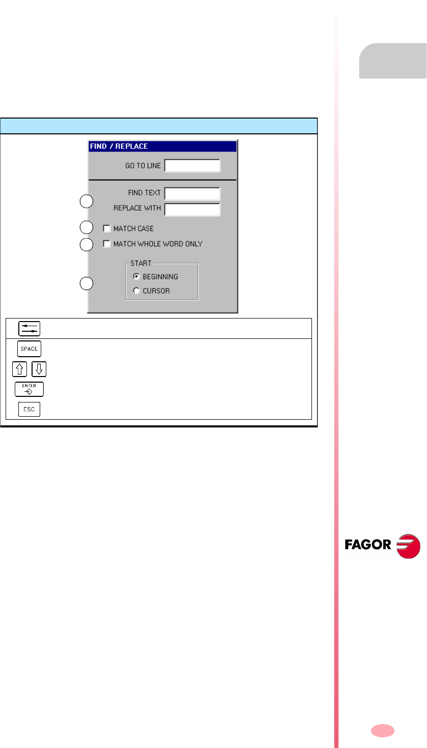
Operation manual
8070 CNC
PLC
Program editing (softkeys)
11.
(SOFT V03.0X)
227
11.4.5 Find/Replace
It is used for searching for a line or a text in a program. It can also replace a text with
another text.
When selecting this option, the CNC shows a dialog box requesting the line number
or the text to look for. When defining a text search, certain options may also be defining
that allow:
A. Replacing the text being searched with another in the program.
B. Ignore uppercase and lowercase.
C. Consider the text to find as a whole word.
D. Select whether the search starts at the beginning of the program or at the cursor
position.
After defining the search options, press [ENTER] to start the search or [ESC] to cancel
it.
The text found in the program will be highlighted and the softkey menu will show the
following options:
•Replace, to replace the highlighted text.
•Replace all, to replace the text throughout the whole program.
•Find next, to skip this text and keep on searching.
To end the search, press [ESC].
Find/replace
To move the cursor through the elements of the list.
To activate/deactivate the selection box (B) (C).
To select an option of a group (D).
To start the search.
To cancel the search and close the dialog box.
A
B
C
D
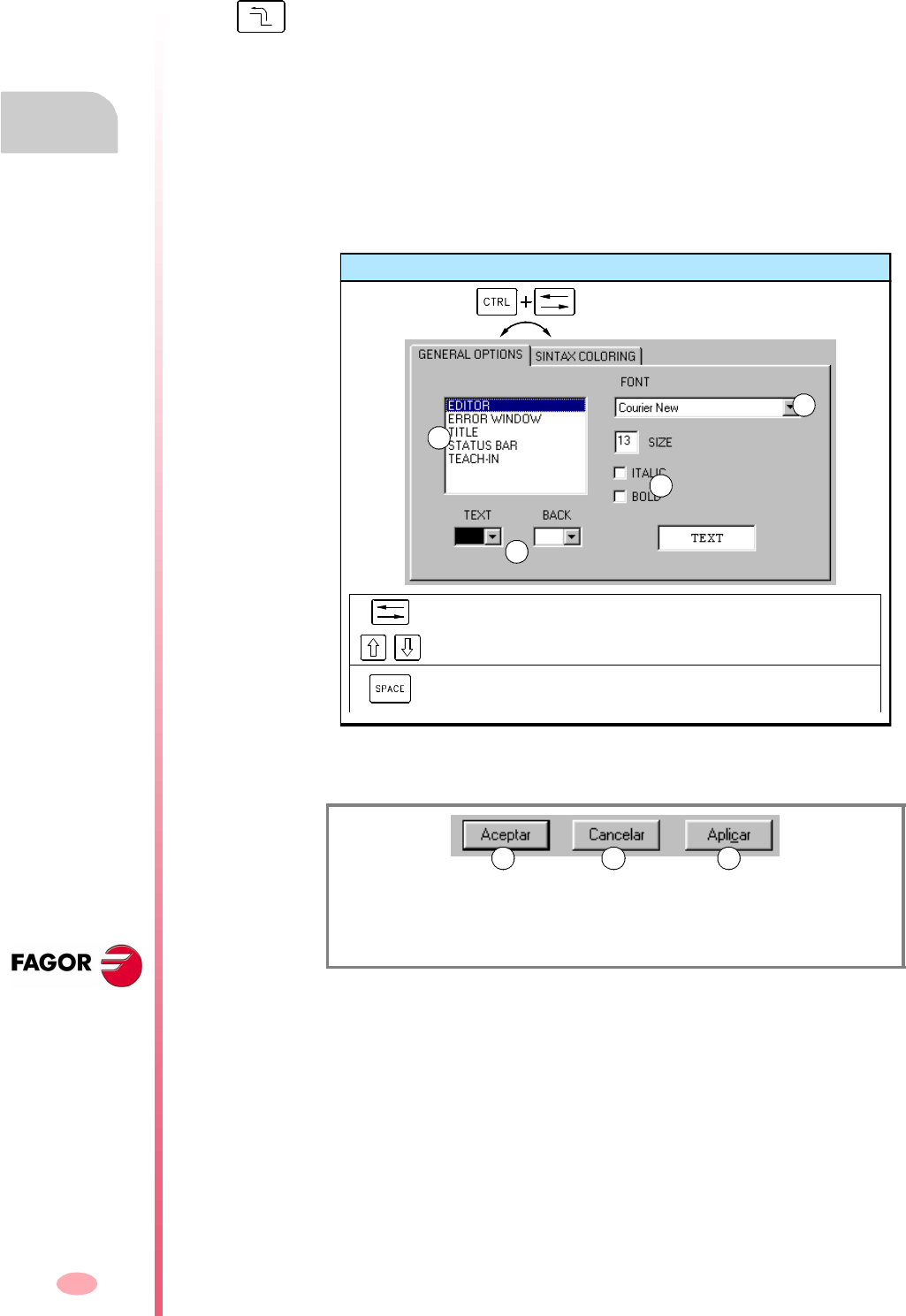
Operation manual
8070 CNC
11.
PLC
Program editing (softkeys)
(SOFT V03.0X)
228
11.4.6 Customizing
It is used for personalizing the appearance and properties of the editing window.
Customizing "Appearance" (looks)
It is used for personalizing the look of the different elements of the editing window
and the colors of the elements of the program.
When selecting this option, the CNC shows the dialog box with two panels. The first
one has the elements of the editing window that may be customized and the second
one those of the program. The panel is selected by the key combination
[CTRL]+[TAB].
After defining the new look, use the cursor to select one of the buttons here below
to accept or ignore the changes made and press [ENTER].
The dialog box may also be closed directly without accepting the changes by pressing
[ESC].
Customizing "Save always" & "Not always"
It is used to save the program automatically or manually.
•When "auto-save" is on, the CNC will automatically save the program after every
change.
•When "manual save" is active, the user must save the program (as explained in
the "11.4.2 File" section of this chapter).
When selecting this option, the softkey menu shows the available options. To return
to the main menu, press the key for the previous menu.
(A) To accept the changes and close the dialog box.
(B) To ignore the changes and close the dialog box.
(C) To apply the changes and close the dialog box.
Set aspect
To move the cursor through the elements of the list.
To select an option of a group (A).
To turn on/off the checkboxes (C), and to open/close the drop lists
(B).
A
B
C
B
A CB
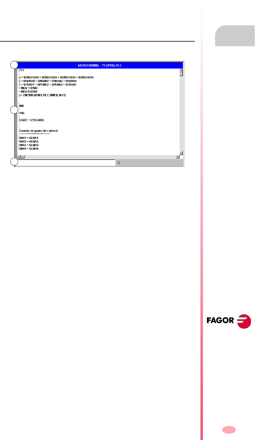
Operation manual
8070 CNC
PLC
Program monitoring
11.
(SOFT V03.0X)
229
11.5 Program monitoring
To monitor a program, select it from the list of the service window and select the
"Monitoring" option of the softkey menu. The CNC will display the monitoring window
and it will show the instructions of the selected program.
To close the monitoring window, press [ESC].
Description of the monitoring window
The editing window shows the following information:
A. Title bar.
It shows the name of the program that is being monitored.
B. Monitoring area.
It shows the status of the instructions being executed. It is a real-time monitoring.
Only the instructions that are being executed are monitored.
The PLC will show, in a different color, the instructions that are not being executed
such as the first cycle or those subroutines whose call is not active. The default
colors are:
C. Data entry area.
It is used to modify the values of the PLC resources.
Red Active variables.
Green Instruction that is not being executed.
Black Inactive variable or comment.
B
A
C
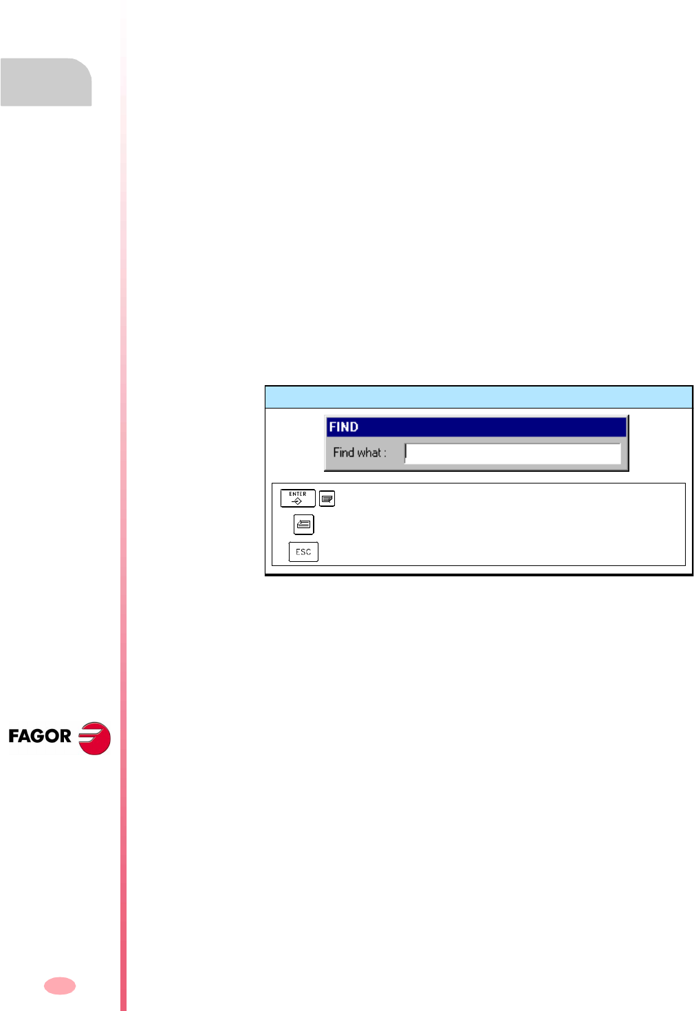
Operation manual
8070 CNC
11.
PLC
Program monitoring (softkeys)
(SOFT V03.0X)
230
11.6 Program monitoring (softkeys)
When selecting the "Monitoring" option of the softkey menu, the following options will
appear.
Monitoring "Size +"
Every time this softkey is pressed, the size of the text will increase.
Monitoring "Size -"
Every time this softkey is pressed, the size of the text will decrease.
Monitoring "Bold"
When selecting this option, the text of the program appears in bold.
Monitoring "OFF/ON"
It interrupts and resumes program monitoring. While monitoring is interrupted, the
resource status changes are not updated.
Interrupting the monitoring does not stop the execution of the PLC.
Monitoring "Find"
To find text in a program.
When selecting this option, the CNC shows a dialog box requesting the text to be
found. Key in the text and press [ENTER] to begin the search.
As the text is being searched, the cursor will position on the match found. To end the
search, press [ESC].
Monitoring "Customize"
It is used to personalize certain functions of the monitoring window. When selecting
this option, the CNC shows a dialog box with the options available for customizing.
Find
To search for the next program (in descending order).
To search for the previous program (in ascending order).
To end the search and close the dialog box.

Operation manual
8070 CNC
PLC
"Commands" service
11.
(SOFT V03.0X)
231
11.7 "Commands" service
The "Commands" service is used to debug the PLC program execution by taking
advantage of the possibility to execute the various parts of the program separately
(first cycle, main module and periodic module). This service also offers the possibility
of starting up and interrupting the execution of the PLC program.
When selecting this service, the horizontal softkey menu offers all the options
associated with this service.
11.7.1 Options of the "Commands" service (softkeys)
Commands "Run"
It starts the execution of the PLC program.
1. The first cycle (CY1) is executed once.
2. Cyclic execution of the main program (PRG) and the periodic module (PE).
The main program is executed according to the frequency defined by machine
parameter.
The periodic module is executed according to the frequency defined in the
program.
Commands "Stop"
It interrupts the execution of the PLC program.
Commands "CY1"
It executes the part of the program corresponding to the first cycle (CY1). The CNC
does not execute this option when the PLC program is running.
Commands "Cycle"
It executes the main program (PRG) once. The CNC does not execute this option
when the PLC program is running.
Commands "Resume"
It resumes the cyclic execution of the PLC program. The CNC does not execute this
option when the PLC program is running.
Commands "PE module"
It executes the periodic module (PE) once. The CNC does not execute this option
when the PLC program is running.
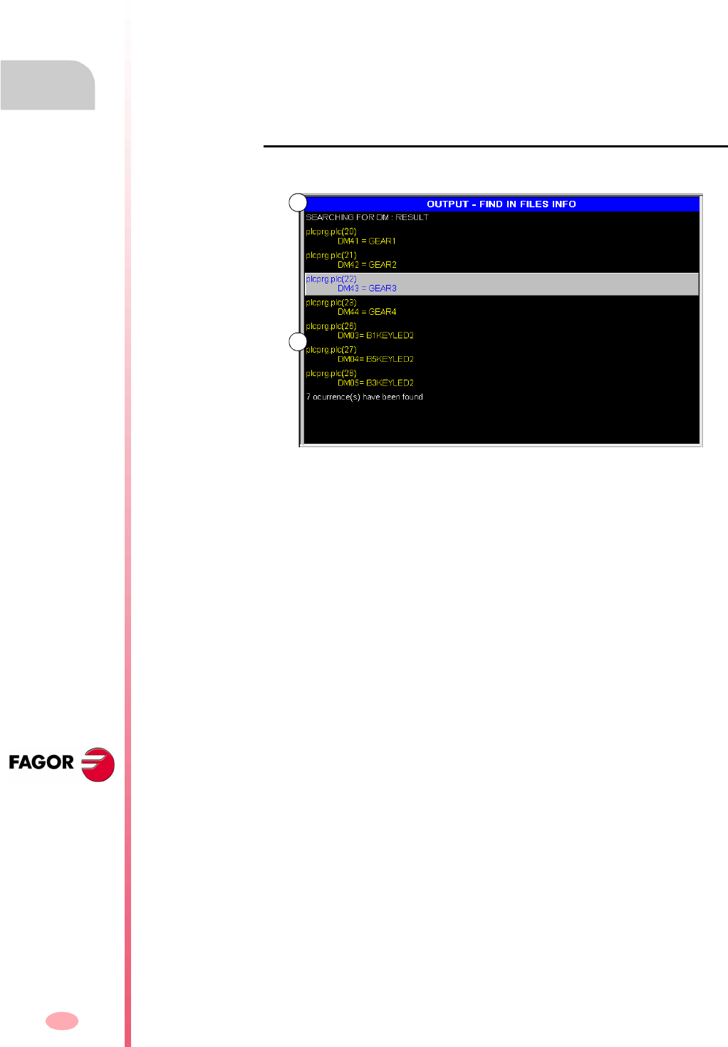
Operation manual
8070 CNC
11.
PLC
"Outputs" service
(SOFT V03.0X)
232
11.8 "Outputs" service
The "Outputs" service shows the following information:
•The result of generating (compiling) the PLC program.
•The result of analyzing a file of mnemonics.
•The result of text search in the files making up the PLC project.
Pressing the "Show" softkey accesses the screen of this service that shows this
information. To close the window, press [ESC].
Description of the outputs service
The screen of this service looks like this:
A. Title bar.
It shows the type of information displayed in the window (information about the
compilation, file analysis or a search).
B. Requested information.
It shows the requested information.
B
A
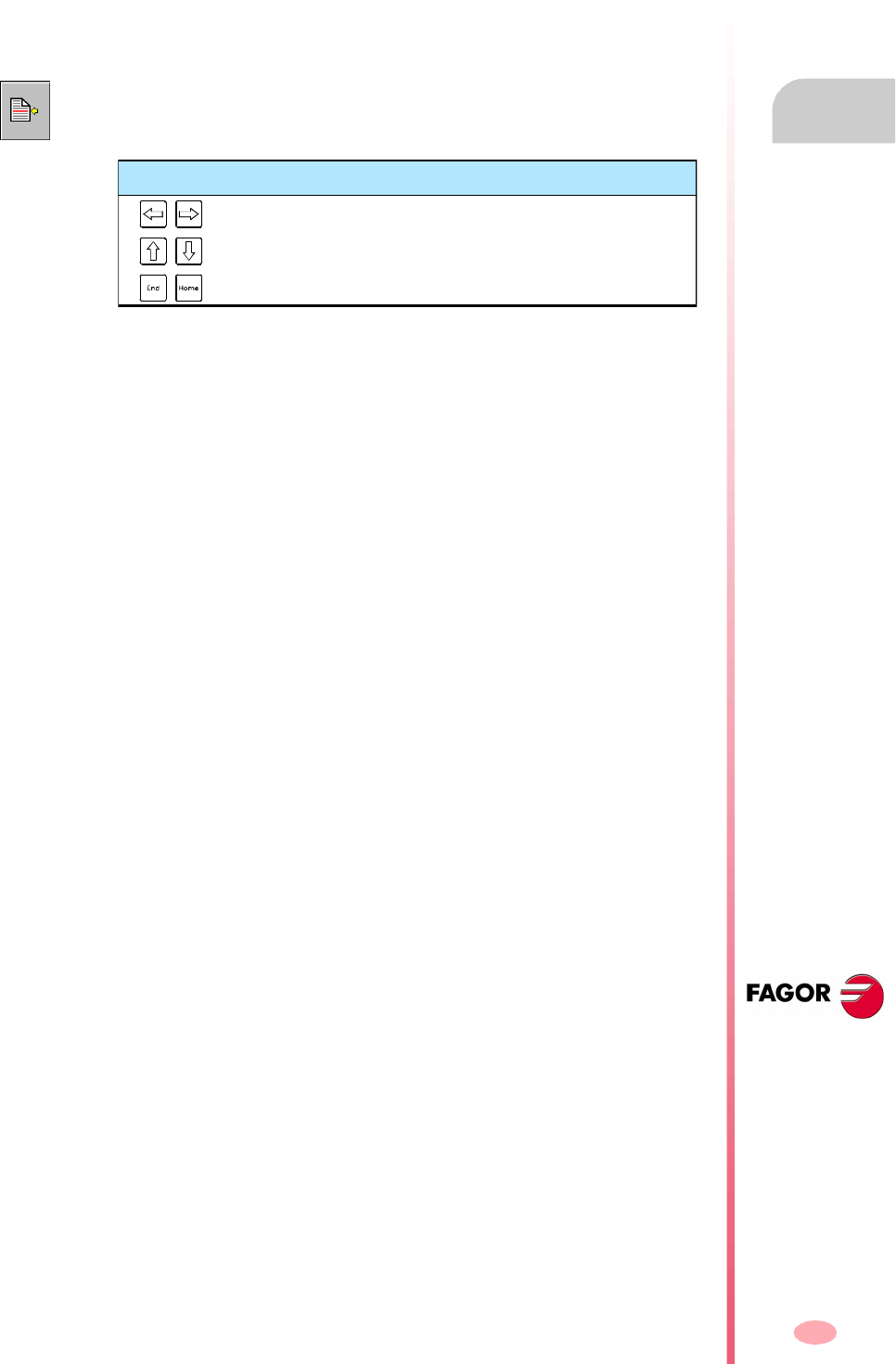
Operation manual
8070 CNC
PLC
"Outputs" service
11.
(SOFT V03.0X)
233
11.8.1 Options of the "Outputs" service
When accessing the "Outputs" service, the softkeys will show the following option.
Outputs "Compiling info"
It shows the result of compiling (generating) the PLC program. The screen shows a
list of warning or errors detected when compiling the PLC program.
Outputs "Checking info"
It shows the result of analyzing the file of mnemonics. The screen shows a list of the
error detected when analyzing the program.
After selecting a warning or error from the list, it is possible to go to the erroneous
line by pressing the relevant icon.
Outputs "Search info"
It shows the result of searching text in the programs making up the PLC project.
After selecting an element from the list, it is possible to go to its line by pressing the
relevant icon.
After selecting a warning or error from the list, it is possible to go to the erroneous
line by pressing the relevant icon.
Keys to move the cursor
To select the previous or next message or error.
To select the previous or next information page.
To select the first or last message or error from the list.
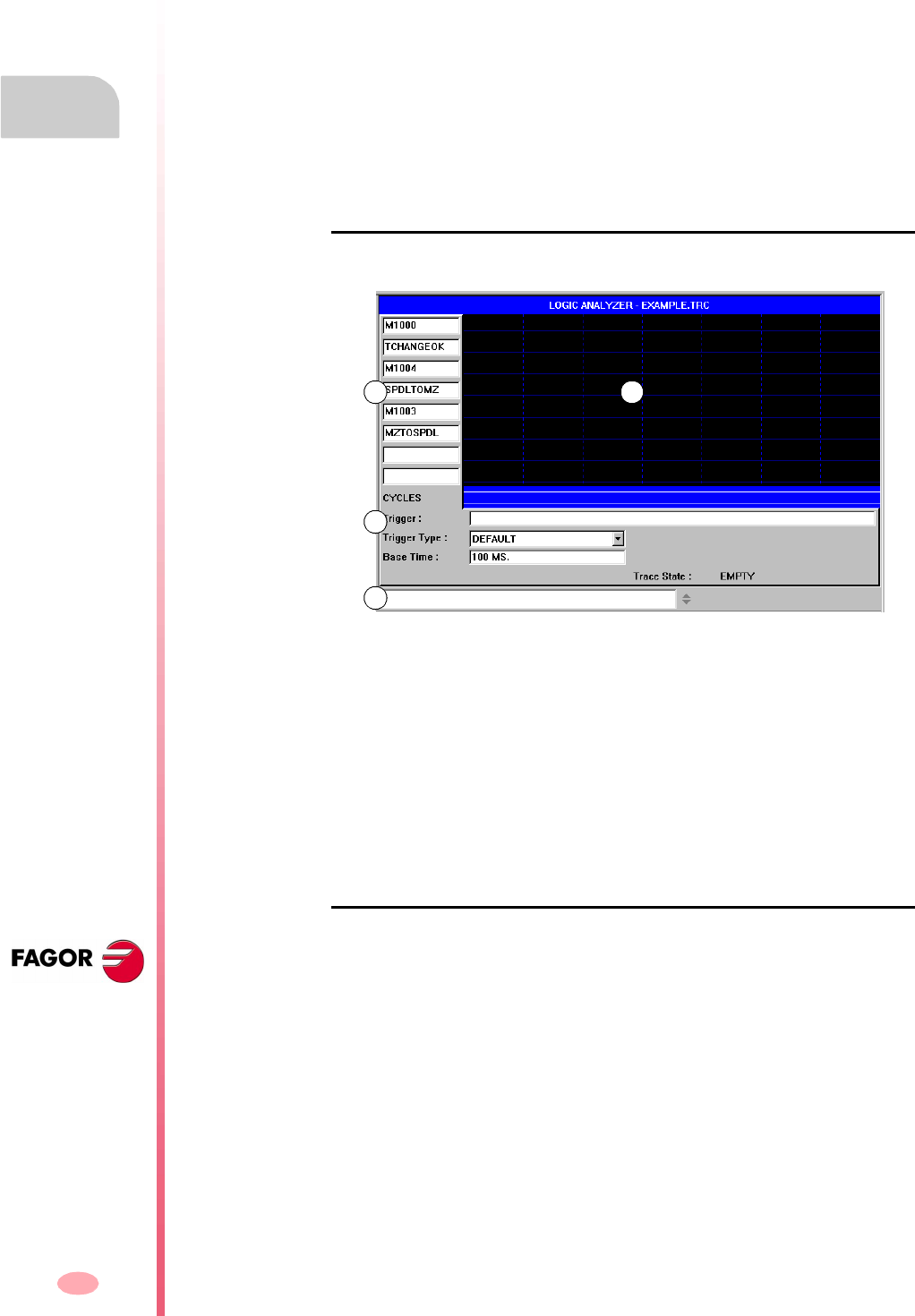
Operation manual
8070 CNC
11.
PLC
"Logic analyzer" service
(SOFT V03.0X)
234
11.9 "Logic analyzer" service
The "Logic analyzer" service is used to analyze the behavior of the logic PLC signals
according to a time base and certain trigger conditions set by the user.
Up to 8 PLC variables or expressions may be analyzed at the same time and the result
of the analysis (the traces) will appear on a graphic interface that facilitates the
interpretation of the data. Once the done capturing data, the user may:
•Modify the time base to display different zooms of the traces.
•Move along the traces to display points, times, time differences, etc.
To close the window, press [ESC].
Description of the logic analizer
The logic analyzer looks like this:
A. The data area is used to define the variables or expressions to be analyzed. Up
to 8 PLC variables or expressions may be defined.
B. The graphic area shows the traces for the defined PLC variables or expressions
and a trace of the PLC cycles with the indicated conditions.
Also, a vertical red line is displayed to indicate the trigger point (if any) and a green
line to indicate the cursor position.
C. The information area is used to define the data that conditions the display of the
traces (trigger, type of trigger, time base and trace status).
D. The data entry area is used to modify the PLC resources.
Softkey menus
When selecting the logic analyzer, the horizontal softkey menu offers all the options
associated with this service. The set of options offered by this menu may be changed
using the "+" softkey which offers a new set of options.
A B
C
D
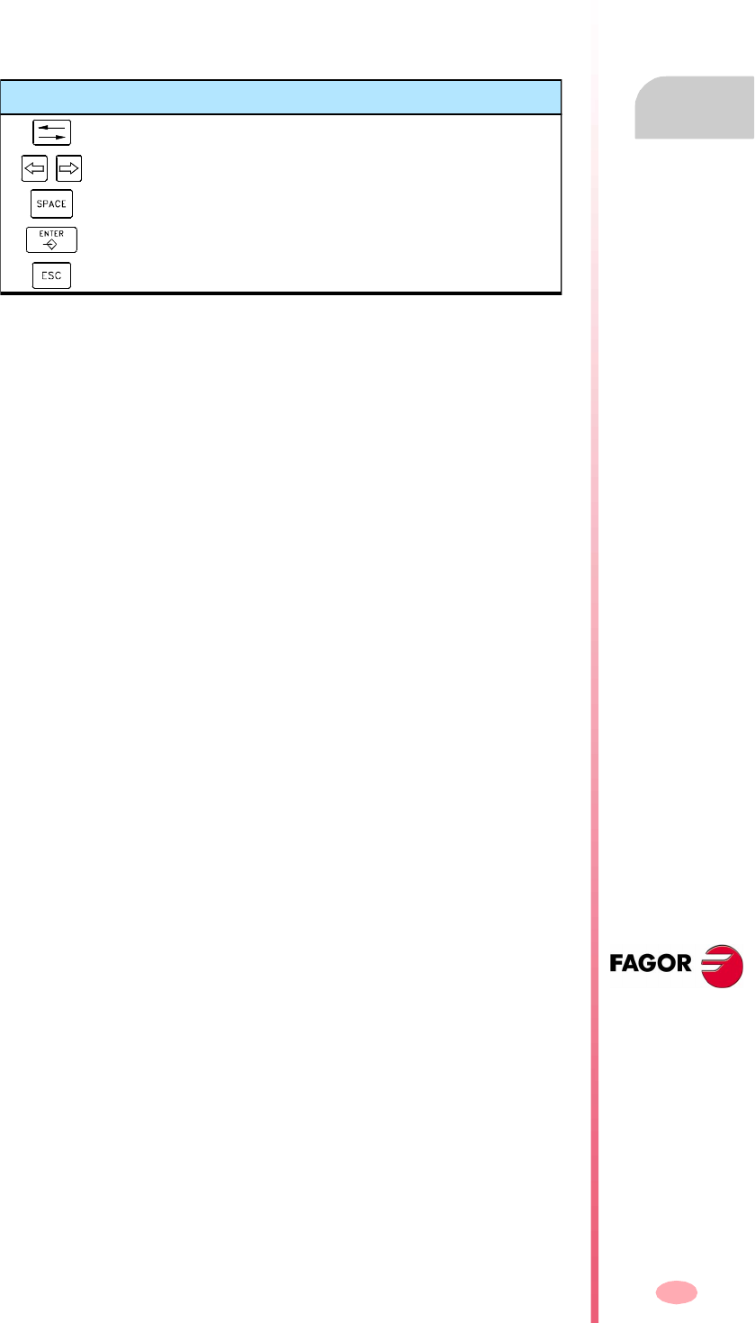
Operation manual
8070 CNC
PLC
"Logic analyzer" service
11.
(SOFT V03.0X)
235
11.9.1 Editing logic analyzer data
In order to capture trace data, the user must enter the variables or expressions to be
analyzed, the trigger type and conditions as well as the time based to be used to
display the captured values.
To edit this data, select the graphic area of the logic analyzer and press the "Edit view"
softkey to place the cursor on the data editing area.
Definition of variables
Up to 8 PLC variables or expressions may be defined to obtain their trace. The
definition of the expression cannot exceed 80 characters.
When modifying a variable, if there was already a trace of that expression, the trace
will be deleted when validating the new edition.
Trigger condition
A trigger condition is the one used to capture data and may be defined with a PLC
variable or expression. The definition of the expression cannot exceed 80 characters.
If the trigger condition is modified after a data capture, all the traces will be deleted
when validating the new condition.
Trigger type
It sets whether the data is to be captured "before", "after" or "before and after" the
selected trigger condition is met.
Time base
The operator may use this parameter to assign the timeframe to each vertical division.
The size of these divisions, therefore the resolution of these signals will be
determined by this time base. Consequently, the smaller the time base, the greater
the signal resolution.
By default The data capture starts and ends when the operator selects the
option to execute and stop the trace.
Before The data capture starts when the trigger condition is met and ends
when the operator selects the option to stop the trace.
Once the trace has been executed, the trigger signal will be shown
at the beginning of the trace.
After The data capture starts when the operator selects the option to
execute the trace and ends when the trigger condition is met.
Once the trace has been executed, the trigger signal will appear
at the end of the trace.
In the middle The data capture starts and ends when the operator selects the
option to execute and stop the trace.
Once the trace has been executed, the trigger signal will be shown
at the center of the trace.
Keys for defining the data of the logic analyzer
To move the cursor through the data.
To move the cursor whitin a data.
To display the drop list menus.
To validate the defined data.
To quit (cancels) editing data.
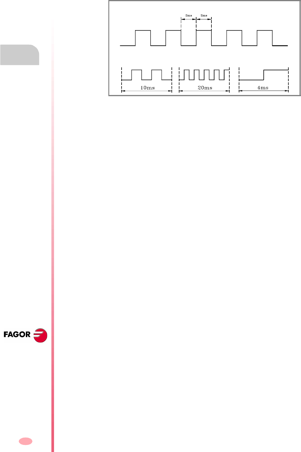
Operation manual
8070 CNC
11.
PLC
"Logic analyzer" service
(SOFT V03.0X)
236
The value is given in milliseconds or microseconds according to the active units and
the selected value will be displayed in the information area.
While the graphic window is selected, use the "+" and "-" keys to divide or multiply
this time base by two.
Start distance / Trigger distance
This data is only shown when there is a trace.
The value is updated when moving the indicator cursor of the graphic area. Its value
may also be edited, thus updating the cursor position in the graphic area.
Reference distance
This data is only shown when there is a trace already and the operator has put a
reference signal. It represents the time difference between the indicator cursor and
the reference signal.
The value is updated when moving the indicator cursor of the graphic area. Its value
may also be edited, thus updating the cursor position in the graphic area.
Trace status
This element cannot be edited, it automatically reflects the status of the trace. The
possible messages are:
•Empty.
•Beginning.
•Executing.
•Stopping.
•Full.
There is a mark that changes states every 2ms.
With a time base of 10ms, 20ms and 4ms it will look like this.
Start distance It represents the time difference between the indicator
cursor and the base point of the trace (beginning of the
trace if there is no trigger point or it has not been
reached).
Trigger distance It represents the time difference between the indicator
cursor and the trigger point (if it has taken place).

Operation manual
8070 CNC
PLC
"Logic analyzer" service
11.
(SOFT V03.0X)
237
11.9.2 Save, load and reset the analyzer configuration
Save the configuration
It is used to save the current configuration of the logic analyzer (PLC variables and
expressions, trigger conditions, graphic traces) into a file.
When selecting this option, the CNC shows a list of trace files (TRC) already saved.
To save the current configuration:
1. Define the file name at the bottom window. To replace an existing file, select it from
the list.
2. Press [ENTER] to save the configuration or [ESC] to return to the logic analyzer
without saving the configuration.
Load the configuration
It is used to recover a logic analyzer configuration that has been stored earlier.
When selecting this option, the CNC shows a list of trace files (TRC) already saved.
To load one of these files:
1. Define the file name at the bottom window or select it from the list.
2. Press [ENTER] to save the configuration or [ESC] to return to the logic analyzer
without loading the configuration.
Initialize the configuration
It is used to reset all the analyzer data eliminating the defined variables or expressions
as well as the trigger condition and trigger type. The traces are also deleted because
there are no variables to be analyzed.

Operation manual
8070 CNC
11.
PLC
"Logic analyzer" service
(SOFT V03.0X)
238
11.9.3 Execute and analyze trace
Execute trace / Stop trace
It used to start or stop the data capture to display the traces.
Analyze trace
It is used to analyze the different graphic aspects of the trace.
•Go to the beginning
It moves the indicator cursor and the current graphic view to the beginning of the
trace.
•Go to the end
It moves the indicator cursor and the current graphic view to the end of the trace.
•Go to the time
It moves the indicator cursor and the current graphic view to the time value set
by the operator with respect to the base point of the trace (starting point of the
trace if there is no trigger or to the trigger point if there is one).
•Go to trigger
It moves the indicator cursor and the current graphic view to the trigger point.
•Go to reference
It moves the indicator cursor and the current graphic view to the reference point
defined earlier.
•Set reference
It sets a reference point at the current cursor position for time difference
calculation.
•Remove reference
Removes the reference point defined earlier.
Trace view / Edit view
It toggles between the graphic window and the data and display conditions area.
MS (milliseconds) / US (microseconds)
It toggles between milliseconds (0.001
-3
seconds) and microseconds (10
-6
seconds).
Print
It is used to print the graph on a printer connected to the CNC or as a BMP file in the
CNC. When printing to a file, it is saved in the folder:
"C:\Cnc8070\Mtb\Plc\Watch\*.bmp"
When selecting this option, the softkey menu shows the options available for
analyzing the trace. To return to the main menu, press the key for the previous menu.
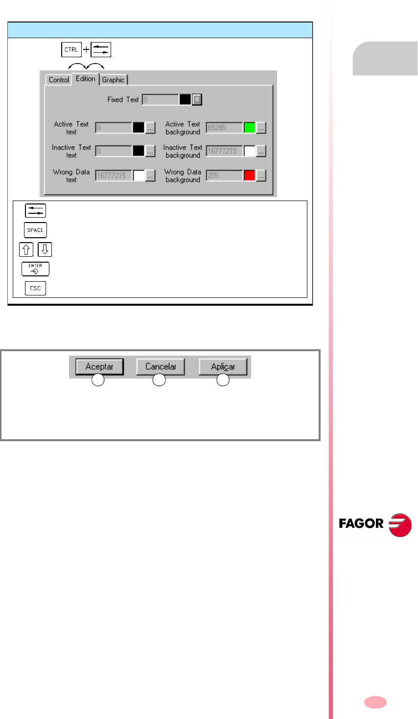
Operation manual
8070 CNC
PLC
"Logic analyzer" service
11.
(SOFT V03.0X)
239
11.9.4 Customize the appearance of the logic analyzer
It is used to customize the looks of the different elements of the logic analyzer.
When selecting this option, the CNC shows a dialog box with the options available
for customizing.
After defining the new look, use the cursor to select one of the buttons here below
to accept or ignore the changes made and press [ENTER].
The dialog box may also be closed directly without accepting the changes by pressing
[ESC].
(A) To accept the changes and close the dialog box.
(B) To ignore the changes and close the dialog box.
(C) To apply the changes and close the dialog box.
Set aspect
To move the cursor through the elements of the list.
To show the color palette.
To select a color from the palette
Accep the selection in the color palette
It cancels the selection in the color palette.
A CB
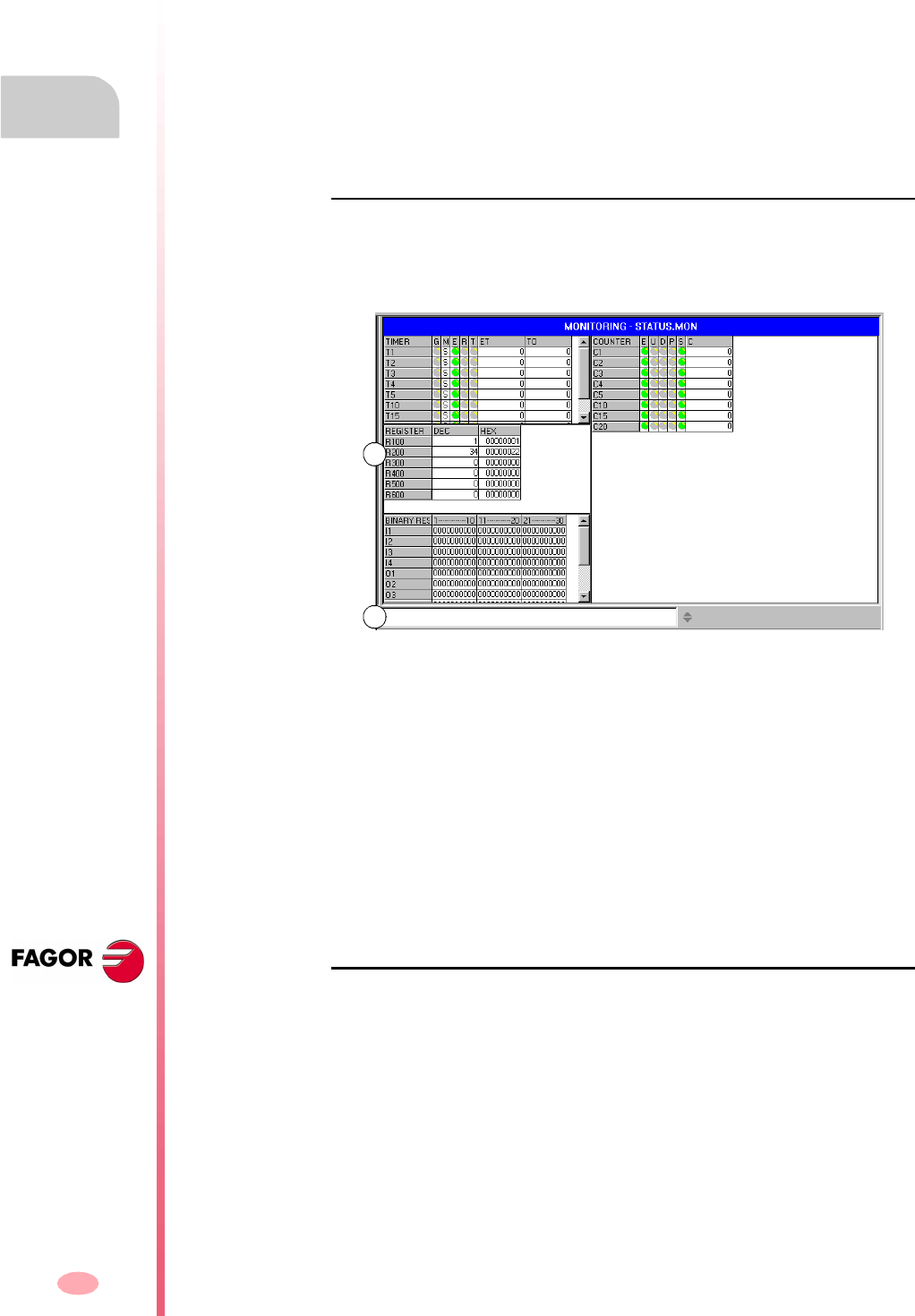
Operation manual
8070 CNC
11.
PLC
"Monitoring" service
(SOFT V03.0X)
240
11.10 "Monitoring" service
This service is used to analyze the status of the various PLC variables and resources.
When selecting the "Monitoring" option at the service window, it will show a list with
the three resource files used last. This will let you recover one of them without having
to define it again.
Pressing the "Show" softkey access the service screen. If a file was selected from
the list, it will show the resources defined in it. To close the monitoring window, press
[ESC].
Description of the monitoring service
This service screen is divided into several windows that may be accessed with the
window switching key.
The monitoring screen looks like this:
A. Resources selected for monitoring.
It shows the user resources and symbols being analyzed. They are shown
grouped in the following tables:
Each of them shows information on the status of those resources.
B. Data entry area.
It is used to define the user resources and symbols to be analyzed and modify
their values by directly assigning a value to them.
Softkey menus
When selecting this service, the horizontal softkey menu will show all the options
associated with resource monitoring. The set of options offered by this menu may be
changed using the "+" softkey which offers a new set of options.
Timers Counters
Registers Binary resources
A
B

Operation manual
8070 CNC
PLC
"Monitoring" service
11.
(SOFT V03.0X)
241
11.10.1 Description of resource tables
As mentioned earlier, the user resources and symbols defined are displayed in
different tables. Each table shows the following information.
Timers
This table shows the timers and user defined symbols for the timers and their status.
This table has the following fields:
The inputs and outputs that are high will be indicated with a green symbol.
Registers
This table shows the registers and user symbols defined for the registers as well as
their values.
The values may be shown in decimal, hexadecimal or binary format.
Binary resources
This table shows the binary resources (inputs, outputs, messages, errors) and the
user defined symbols for the binary resources as well as information on the their
status.
Counters
This table shows the counters and user symbols defined for the counters as well as
their status.
This table has the following fields:
The inputs and outputs that are high will be indicated with a green symbol.
G It indicates whether any of the trigger inputs of the timer is active (TG1,
TG2, TG3 or TG4).
M Timer status:
S - Stopped.
T - Timing.
D - Disabled.
E Status of the Enable input (TEN).
R Status of the Reset input (TRS)
T Status output.
ET Elapsed time.
TO Remaining time.
E Status of the enable input (CEN).
U Status of the Count-up input (CUP).
D Status of the Countdown input (CDW).
P Status of the preset input (CPR).
S Status output.
C Value of the internal count of the counter.
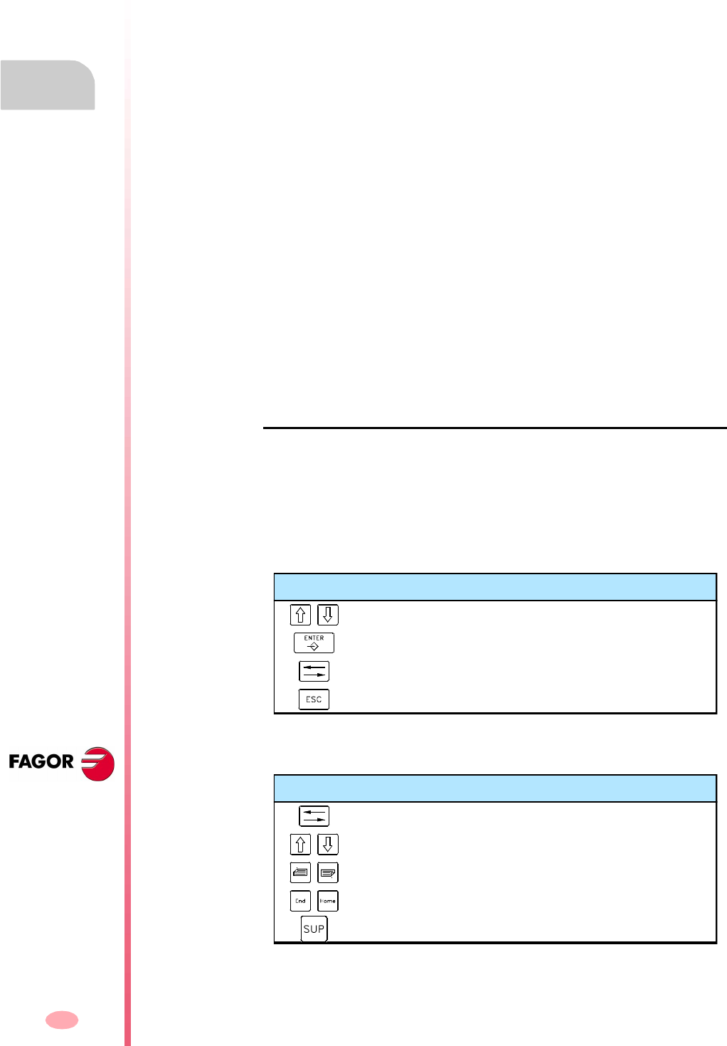
Operation manual
8070 CNC
11.
PLC
"Monitoring" service
(SOFT V03.0X)
242
11.10.2 Definition of the table resources
Each table shows the following resources and user symbols:
Timer table
•Timers (T1...T256).
•User symbols defined for the timers.
Counter table
•Counters (C1...C256).
•User symbols defined for the counters.
Register table
•Registers (R1...R1024).
•User symbols defined for the registers.
•PLC-CNC register variables.
Binary resource table
•Inputs (I1...I1024) and outputs (O1...O1024).
•Marks (M1...M8192).
•Messages (MSG1...MSG256) and errors (ERR1...ERR256).
•User symbols defined for the binary resources.
•CNC-PLC boolean variables.
When defining a resource or user symbol, it will be added to the corresponding table.
Data entry
The resources and user symbols of the tables are defined at the data entry area. Their
values may be changed by directly assigning a value to them (M110=1, R300=34).
If it is a hexadecimal value, it must be preceded by the "$" sign (M10=$1, R200=$20).
The window saves the last "N" assignments so they can be recalled later on. In order
to make selecting easier, it is possible to display a window with the list of the
assignments already made.
To remove a resource or user symbol from a table, select that element and press
[SUP].
Keys for defining the data of the logic analyzer
To select the assignments.
To assume the selected assignments.
To show the list of the assignments made.
To close the list of the assignments made.
Keys for defining the data of the logic analyzer
To select one of the tables.
To moves the cursor element by element.
To move the cursor page by page in the table.
To move the cursor to the beginning or end of the table.
To delete the selected resource of the table.
Operation manual
8070 CNC
PLC
"Monitoring" service
11.
(SOFT V03.0X)
243
11.10.3 Options of the "Monitoring" service (softkeys).
When accessing the "Monitoring" option of the softkey menu, the following options
will be available.
Save set
It is used to save the set of defined resources into a file.
When selecting this option, the CNC displays a window with the list of the files (.MON)
currently saved. To save a set of defined resources:
1. Define the file name at the bottom window. To replace an existing one, select it
from the list.
2. Press [ENTER] to save the program or [ESC] to cancel the selection and close
the program listing.
Load set
It is used to recover the set of resources previously saved into a file.
When selecting this option, the CNC shows a window with the list of available files.
To load one of these files:
1. Define the file name at the bottom window or select it from the list.
2. Press [ENTER] to load the selected file or [ESC] to cancel the operation and close
the program listing.
Binary
It toggles between displaying the register values in decimal and hexadecimal format
or only in binary.
Visibility
It shows or hides certain resource tables.
Add row
It increases the size of the active window (where the cursor is) by adding a file to it.
Remove row
It decreases the size of the active window (where the cursor is) by removing a row
from it.
Data input
It selects the data entry area.
Clear all
It deletes all the resources from the tables.
To move the cursor through the active tables.
To move the cursor through the active tables.
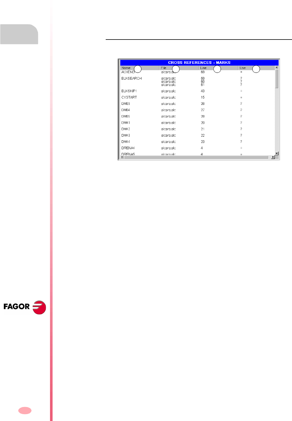
Operation manual
8070 CNC
11.
PLC
"Cross references" service
(SOFT V03.0X)
244
11.11 "Cross references" service
The "Cross references" service may be used to obtain information about the PLC
resources being used in the PLC project.
Pressing the "Show" softkey accesses the window of this service. To close the cross-
reference window, press [ESC].
Description
The screen of this service looks like this:
A. Name of the resources being used by the PLC project.
B. File of the PLC project where the resource is being used.
C. Line, within the file, containing the resource.
D. How the resource is being used.
For the inputs, outputs, marks and registers:
For the timers.
For the counters.
? The resource is used as a consultation.
= The resource is used as an action.
TG Timer trigger.
T Status consultation.
TEN Enable input.
TRS Reset input.
C Status consultation.
CPR Counter preset.
CEN Enable input.
CUP Count-up input.
CDW Countdown input.
A B C D
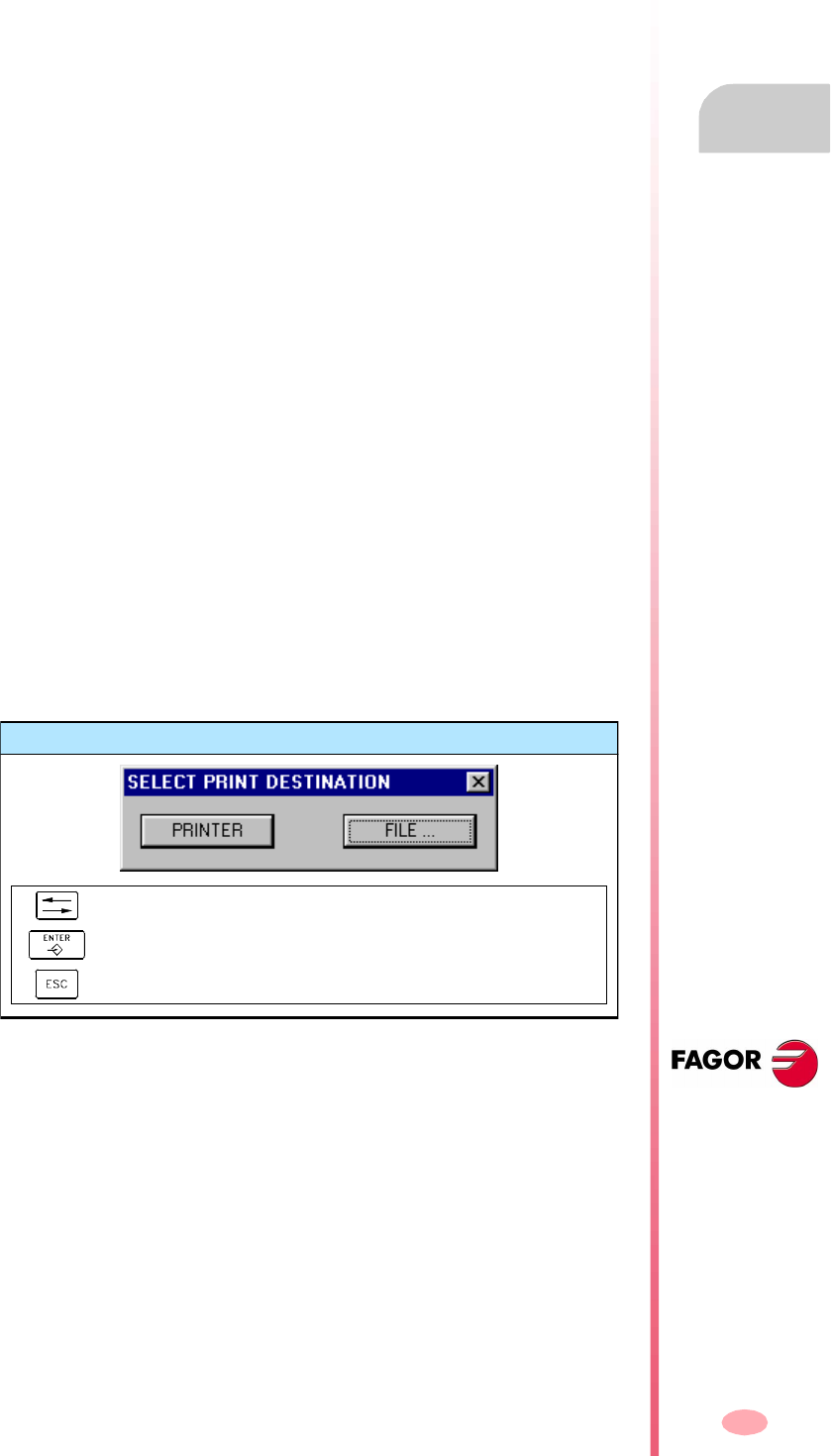
Operation manual
8070 CNC
PLC
"Cross references" service
11.
(SOFT V03.0X)
245
11.11.1 Options of the "Cross reference" service (softkeys)
When accessing the "Cross reference" service, the softkey menu will offer the
following options:
Inputs
It shows information about the inputs.
Outputs
It shows information about the outputs.
Marks
It shows information about the marks.
Registers
It shows information about the registers.
Timers
It shows information about the timers.
Counters
It shows information about the counters.
Print
It is used to print the cross reference tables out to a printer connected to the CNC
or as a "*.PRN" file at the CNC. When printing to a file, it is saved in the folder:
"C:\Cnc8070\Users\Reports\*.prn"
When selecting this option, the CNC shows a dialog box requesting the destination
for the file (printer or file). When printing to a file, it is possible to select the name and
location of the file.
After selecting the destination, press [ENTER] to print the table or [ESC] to cancel it.
Print destination
To select the print destination.
To print the drawing.
To cancel the printing.
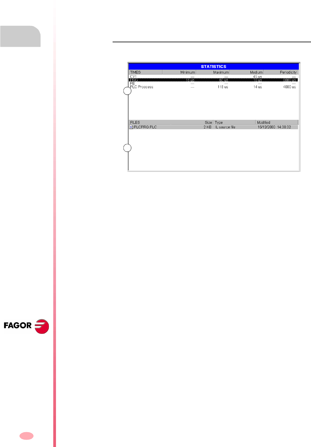
Operation manual
8070 CNC
11.
PLC
"Statistics" service
(SOFT V03.0X)
246
11.12 "Statistics" service
The "Statistics" service may be used to obtain information about the execution times
of the PLC and the files making up the PLC project.
Pressing the "Show" softkey access the service screen. To close the statistics screen,
press [ESC].
Description
The screen of this service looks like this:
A. Execution time-table.
This table shows the following data (from left to right):
•Modules making up the PLC program.
•Minimum module execution time.
•Maximum module execution time.
•Average module execution time.
•Module execution frequency.
B. PLC file table.
This table shows the following data (from left to right):
•Files making up the PLC project.
•Size of each file.
•File type.
•Date last modified.
A
B
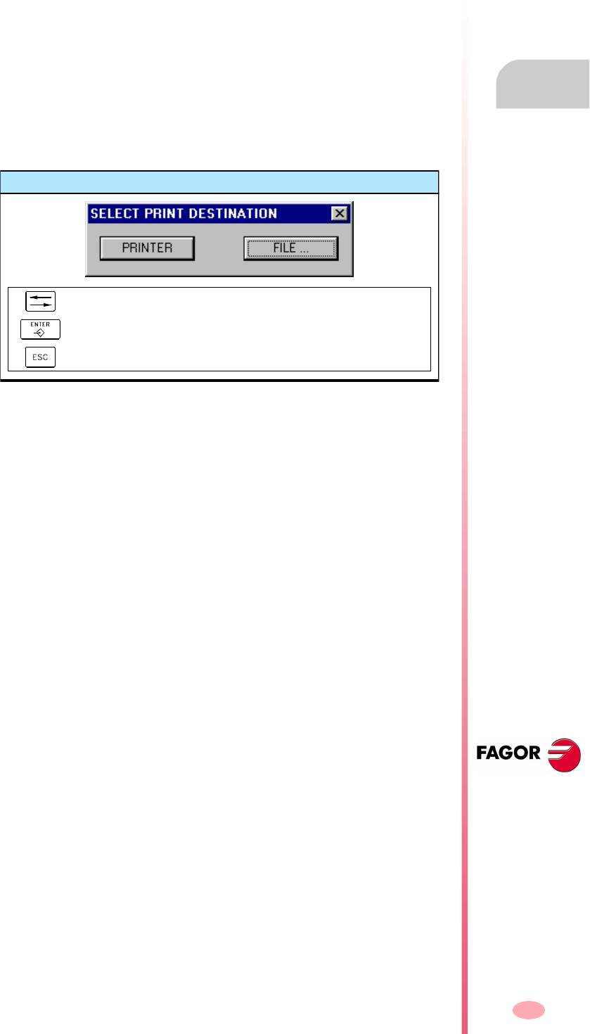
Operation manual
8070 CNC
PLC
"Statistics" service
11.
(SOFT V03.0X)
247
11.12.1 Options of the "Statistics" service (softkeys)
Refresh
It refreshes the table information.
Print
It is used to print the tables out to a printer connected to the CNC or to a file (*.PRN)
at the CNC. When printing to a file, it is saved in the folder:
"C:\Cnc8070\Users\Reports\*.prn"
When selecting this option, the CNC shows a dialog box requesting the destination
for the file (printer or file). When printing to a file, it is possible to select the name and
location of the file.
After selecting the destination, press [ENTER] to print the table or [ESC] to cancel it.
Print destination
To select the print destination.
To print the drawing.
To cancel the printing.
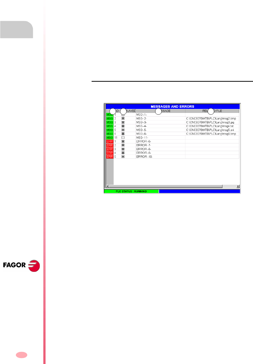
Operation manual
8070 CNC
11.
PLC
"Messages" service
(SOFT V03.0X)
248
11.13 "Messages" service
The "Messages" service may be used to edit the texts associated with PLC messages
and errors. These files may also be displayed and edited (and thus translated into
other languages) using any text editor.
The message and error files are stored in the folder:
"C:\CNC8070\MTB\PLC\LANG"\<language>" corresponding to the language active
at the CNC. To use messages and errors in other languages, copy the files to the folder
of the desired language.
On CNC power-up, the messages and errors are loaded from the folder
corresponding to the language active at the CNC.
Pressing the "Show" softkey access the service screen. To close the message
window, press [ESC].
Description
This screen shows the messages (MSG) and errors (ERR) defined at the PLC. The
screen shows the following table:
A. Message or error identifier.
Number, between 1 and 256, that identifies the message (MSG) or the error
(ERR). The numbering needs not be sequential.
B. Display of the additional information files.
It indicates whether to show or not the file for additional information when
displaying the message. When it comes to errors, it cannot be edited.
C. Text of the message or error displayed for the user.
D. Address of the additional information file.
It may be a text file (*.txt), image file (*.bmp, *.jpg), a combination of both (*.htm,
*.html) or a video (*.avi). When it comes to errors, it cannot be edited because
they cannot be assigned an information file.
A B C D

Operation manual
8070 CNC
PLC
"Messages" service
11.
(SOFT V03.0X)
249
11.13.1 Options of the "Messages" service (softkeys)
Save
It saves the message and error table into a file in ASCII format (*.MEF).
The contents of the table may be saved at the CNC, in a floppy disk or in another CNC
(or PC) via Ethernet.
Load
It recovers the table values saved earlier in the hard disk of the CNC.
Print
It prints the message and error table out to a printer connected to the CNC or as a
file (*.PRN format) at the CNC.
New message
It is used to define a new message in the table.
New error
It is used to define a new error in the table.
Select information
It selects the file for additional information.
Delete
It deletes the selected message or error from the table.
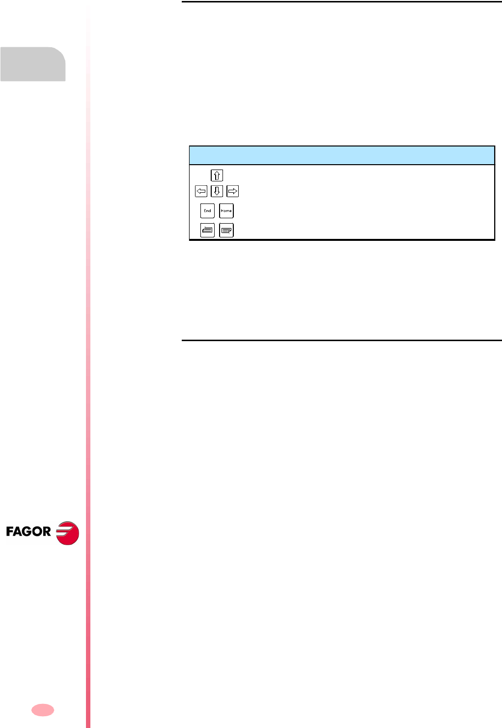
Operation manual
8070 CNC
11.
PLC
"Messages" service
(SOFT V03.0X)
250
11.13.2 Editing the message and error table
Messages
To add a new message to the table, press the "New message" softkey. The CNC adds
a new row to the table and it identifies it with the label -MSG-, indicating that it
corresponds to a message.
To edit or modify the table data, use the cursor to select the cell whose value is to
be changed and define the data as follows:
•The number and text of the message is entered directly from the keyboard.
•The "show" option is turned on and off with the [SPACE] key.
•The file for additional information may be entered directly or may be selected with
the "Select Info" softkey.
Press [ENTER] every time a data is edited to accept the new value or [ESC] to cancel
it.
To delete a message from the table, select it with the cursor and press the "Delete"
softkey.
Errors
To add a new error to the table, press the "New error" softkey. The CNC adds a new
row to the table and it identifies it with the label -ERR-, indicating that it corresponds
to an error.
To edit or modify the table data, use the cursor to select the cell whose value is to
be changed and define the data as follows:
•The number and text of the error are entered directly from the keyboard.
•The "show" option and the file for additional information cannot be edited.
Press [ENTER] every time a data is edited to accept the new value or [ESC] to cancel
it.
To delete an error from the table, select it with the cursor and press the "Delete"
softkey.
Keys for defining the data of the logic analyzer
To move the cursor to the upper, lower, left or right cell.
To move the cursor to the beginning / end of the row.
To move the cursor to the beginning/end of the column.
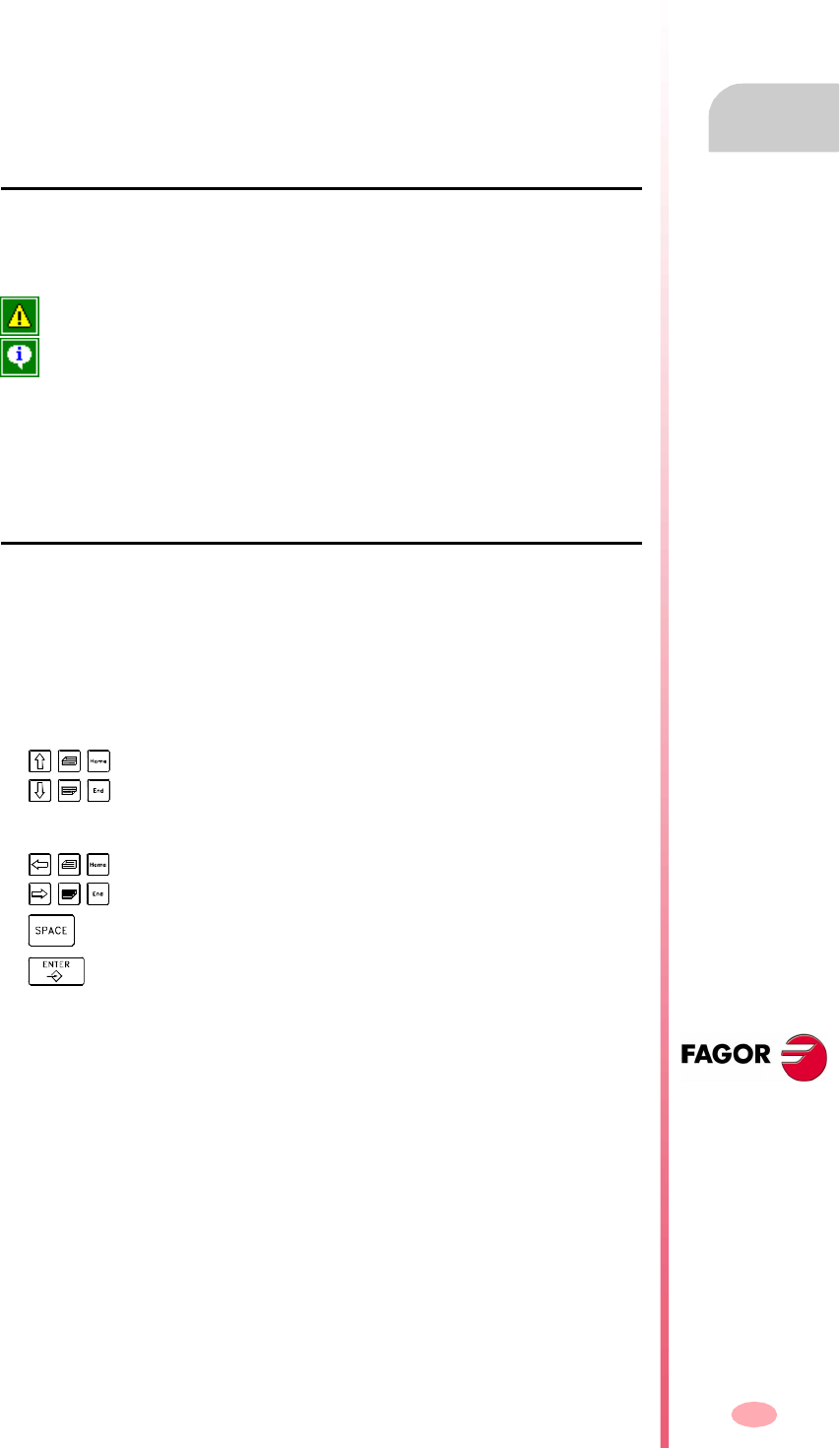
Operation manual
8070 CNC
PLC
"Messages" service
11.
(SOFT V03.0X)
251
11.13.3 Displaying PLC messages
When activating a message (marks "MSG1" through "MSG256"), the PLC message
window (top right ) shows the message number and its associated text. If the message
has been defined so it shows a file with additional information, it will be displayed at
full screen (if the file does not exist, a blue screen will be displayed).
If there are several active messages, it will display the one with highest priority (the
one with lowest number). It will also show the "+" sign next to the PLC message
window to indicate that there are more messages activated by the PLC.
Message window
In order to expand the PLC message window and display the active message list,
press the key combination [CTRL]+[M]. The list will show a symbol next to each
message to indicate that it has a file with additional information associated with it.
To display a message, select it with the cursor and press [ENTER]. If the message
has an additional information file, it will be displayed on the screen. To close the
additional information window, press [ESC].
File with additional information
The files with additional information, defined by the machine manufacturer, may be
displayed automatically when activating the message (if so defined in the message
table) or when requested by the user (at the message window).
The following keys are available to move around in the additional information window
depending on the type of file displayed (TXT, BMP, JPG, HTM, HTML or AVI):
•TXT, BMP, JPG, HTM, HTML file.
•AVI file.
It does not have a file with additional information.
It has a file with additional information.
To move the window contents up or down one line, one page or
everything.
To stop and moves the video forward or backward 1 frame, 5 frames
or the whole video.
To stop the video.
To play the video.

Operation manual
8070 CNC
11.
PLC
"Messages" service
(SOFT V03.0X)
252
11.13.4 Displaying PLC errors
When activating an error (marks "ERR1" through "ERR256"), part-program execution
is interrupted and the center of the screen displays a window with the error number
and its associated text.
Error window
When there is an active error, no other action but deleting it is allowed.
Although the error window disappears from the screen when pressing [ESC], the
error state is not eliminated. To get out of the error state, press [RESET].
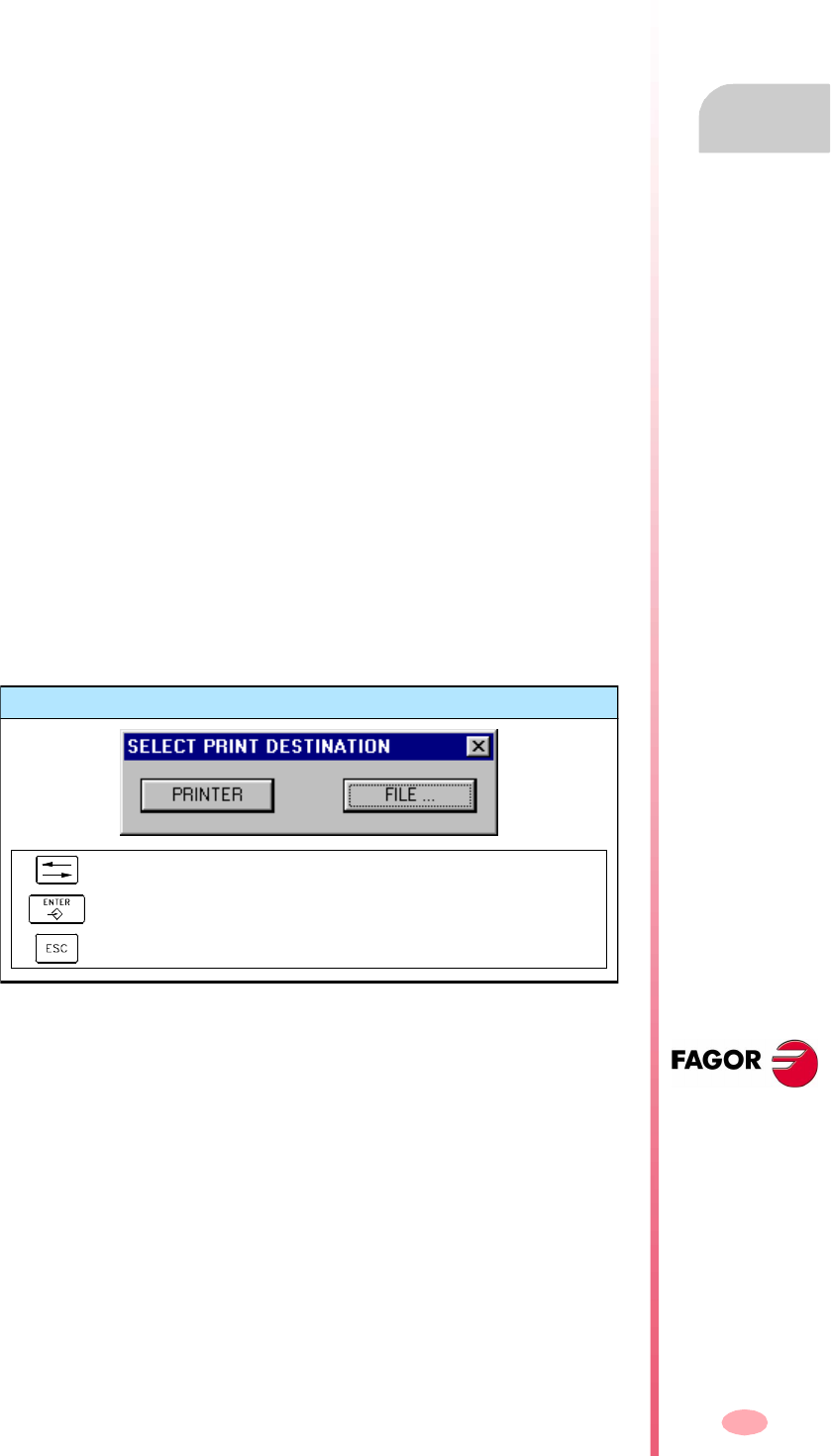
Operation manual
8070 CNC
PLC
"Messages" service
11.
(SOFT V03.0X)
253
11.13.5 Save, load and print a message and error table
Save table
To save the table data, press the "Save" softkey and the CNC will show a list with the
files saved at the CNC.
To save the table data:
1. Select the destination folder.
2. Define the file name at the bottom window. To replace an existing file, select it from
the list.
3. Press [ENTER] to save the file or [ESC] to cancel the operation.
The file will be saved with the extension: *.MEF.
Load table
To recover the table data, press the "Load" softkey, the CNC will show a list with the
files available at the CNC.
To load the table data:
1. Select the folder where the file is.
2. Select the file or write its name at the bottom window.
3. Press [ENTER] to accept the selection or [ESC] to cancel it and close the file
listing.
Print table
It prints the message and error table out to a printer connected to the CNC or as a
file (*.PRN format) at the CNC. When printing to a file, it is saved in the folder:
"C:\Cnc8070\Users\Reports\*.prn"
When selecting this option, the CNC will show a dialog box requesting the destination
for the table (printer or file).
After selecting the destination, press [ENTER] to print the table or [ESC] to cancel it.
Print destination
To select the print destination.
To print the drawing.
To cancel the printing.

Operation manual
8070 CNC
11.
PLC
"Messages" service
(SOFT V03.0X)
254

255
CNC 8070
(SOFT V03.0X)
12
MACHINE PARAMETERS
In order for the machine tool to be able to properly execute the programmed
instructions, the CNC must know the specific data of the machine such as feedrates,
accelerations, feedback, automatic tool change, etc.
This data is set by the machine manufacturer and must be defined in the machine
parameter table.
Selecting the machine parameter tables
What can you do in this work mode?
The machine parameter operating mode offers the following operations:
•Edit and modify the machine parameter tables.
•Validate the machine parameter tables.
•Saving the table contents.
•Recalling the table contents.
•Printing the table contents.
•Initializing the tables.
The machine parameter tables may be edited in this mode or be copied from a floppy
disk or other peripheral connected to the CNC via Ethernet.
The machine parameter tables may be accessed either using the user key if it has
been set accordingly or from the task window. The task window may be accessed
with key combination [CTRL]+[A].

Operating manual
CNC 8070
12.
MACHINE PARAMETERS
(SOFT V03.0X)
256
Parameter setting
To set the machine parameter tables, proceed as follows:
1. Edit the values of the tables.
First, set the general machine parameters because they define the axes of the
machine, thus the axis machine parameters.
The general machine parameters can also be used to define the data for the cross
compensation.
Use the axis machine parameters to determine whether leadscrew error
compensation will be applied or not and define the data of the corresponding
table.
2. Validate the table data.
This operation is a must after defining the parameters of the tables and every time
any of the data is modified.
3. Save the data of the table.
It is recommended to save the data of the machine parameter table so as to have
a backup copy of them. The data may be stored at the CNC, in a floppy disk or
at another CNC (or PC) connected through Ethernet.

Operating manual
CNC 8070
MACHINE PARAMETERS
Appearance of the machine parameter tables
12.
(SOFT V03.0X)
257
12.1 Appearance of the machine parameter tables
When this mode is active, it will be indicated at the top right side of the general status
bar.
The available machine parameter tables are:
•General parameters.
•Axis and spindle parameters.
•Jog parameters.
•Parameters related to the "M" functions.
•Parameters for kinetics.
•Parameters for the magazines.
•HMI parameters.
•OEM parameters.
Standard configuration
The standard configuration of this work mode, described in this manual corresponds
to the one supplied by Fagor. In some cases, the manual shows a sample screen,
instead of that of the CNC in order to make it easier to understand.
This operating mode consists of several tables. The various tables may be selected
using the horizontal softkeys. If while one of the tables is selected, the previous menu
key is pressed, that table will be deselected.
Operating manual
CNC 8070
12.
MACHINE PARAMETERS
Appearance of the machine parameter tables
(SOFT V03.0X)
258
12.1.1 Icon description (vertical softkeys)
The icons are activated with their associated softkey (F8 to F12).
List of icons
The icon menu offers all the options for the selected table. The group of icons of this
menu may be expanded with the softkey associated with the "+" icon that offers a new
set of icons.
Display units (millimeters/inches)
To toggle between the two types of units used to represent the parameters that
depend on those units (coordinates, feedrates, etc.).
The icon highlights the units currently selected (millimeters or inches).
Initialize table
It resets all the parameters to their default values.
The CNC will request confirmation of the command.
Find text
It is used to find a text or a value in the table.
When selecting this option, the CNC shows a dialog box requesting the text to be
found.
Validate table
For validating the table data. If there is no table selected, all the data of all the tables
will be validated.
This table is necessary after changing a data. In certain cases, the CNC will have
to turned off and back on in order for the data to be validated.
Save tool
It saves the values of the table into a file. If there is no table selected, all the data of
all the tables will be saved.
This file may be saved at the CNC, in a floppy disk or at another CNC (or PC)
connected through Ethernet.
Recall table
It restores the values of the table previously saved into a file. If there is no table
selected, all the data of all the tables will be recalled.
Print table
It prints the contents of the table out to a printer connected to the CNC or as a file
(*.PRN format) at the CNC.

Operating manual
CNC 8070
MACHINE PARAMETERS
Appearance of the machine parameter tables
12.
(SOFT V03.0X)
259
Activate TEACH-IN
It is used for activating the TEACH-IN work mode in order to set the leadscrew and
cross compensation tables.
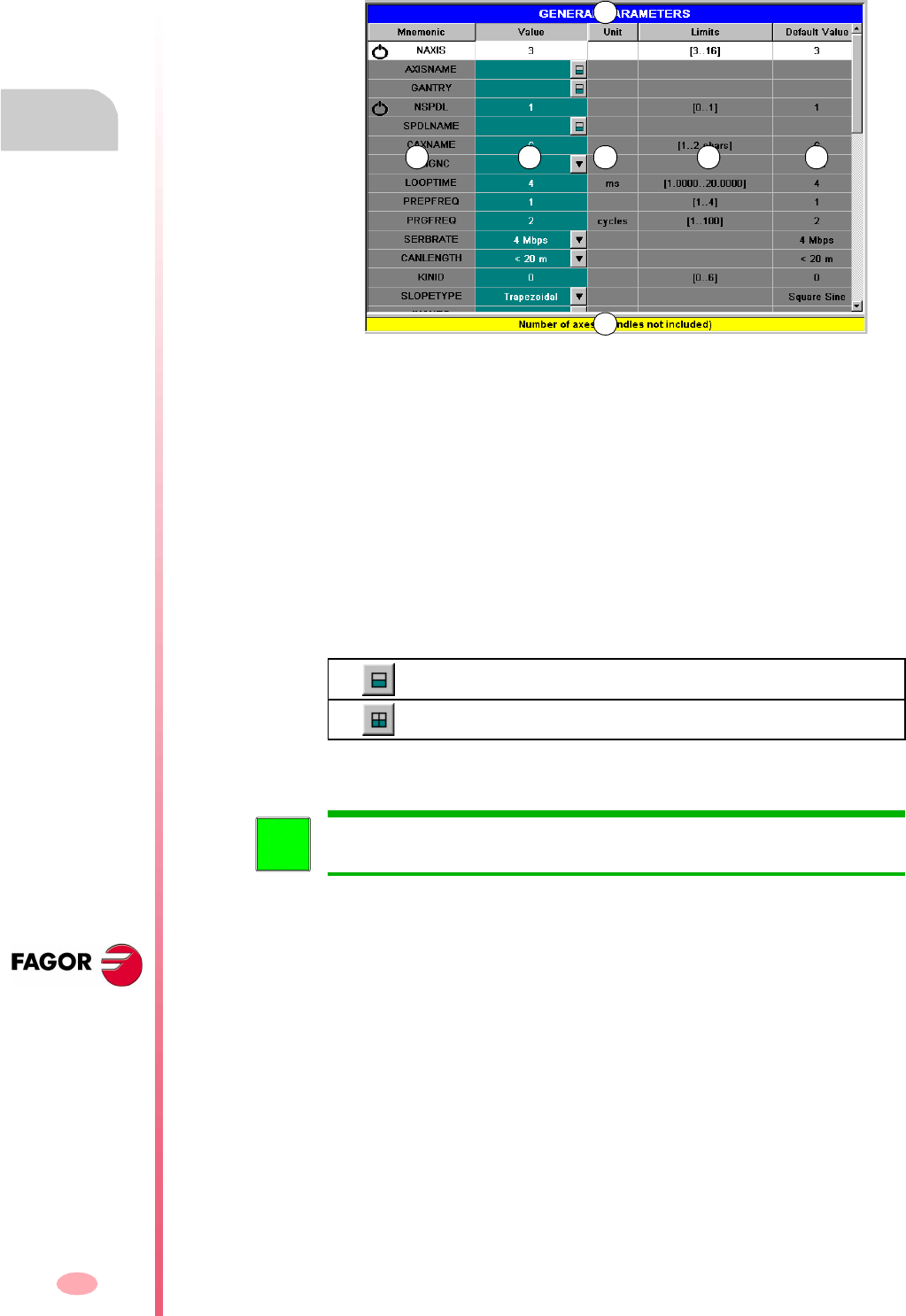
Operating manual
CNC 8070
12.
MACHINE PARAMETERS
Parameter table description
(SOFT V03.0X)
260
12.2 Parameter table description
The machine parameter tables have the following structure:
A. Name of the selected machine parameter table.
B. Parameter list.
C. Parameter value, set by the user.
D. Units used to define the parameter.
E. Limit values for the parameter.
F. Default value of the parameter.
G. Parameter description.
The section on "12.3.1 Data editing and validation" in this chapter shows how to
edit the parameters of the tables.
Certain parameters cannot be edited; they only access a set of parameters or a data
table. These parameters will be identified as follows.
To access the data associated with the parameter, select the parameter with the
cursor and press [ENTER]. To return to the previous parameter table, press [ESC].
To access a group of parameters.
To access a data table.
A
B C D E F
G
To obtain further information about the data appearing in the table, refer to the
chapter on machine parameters of the Installation and Start-up Manual.
i
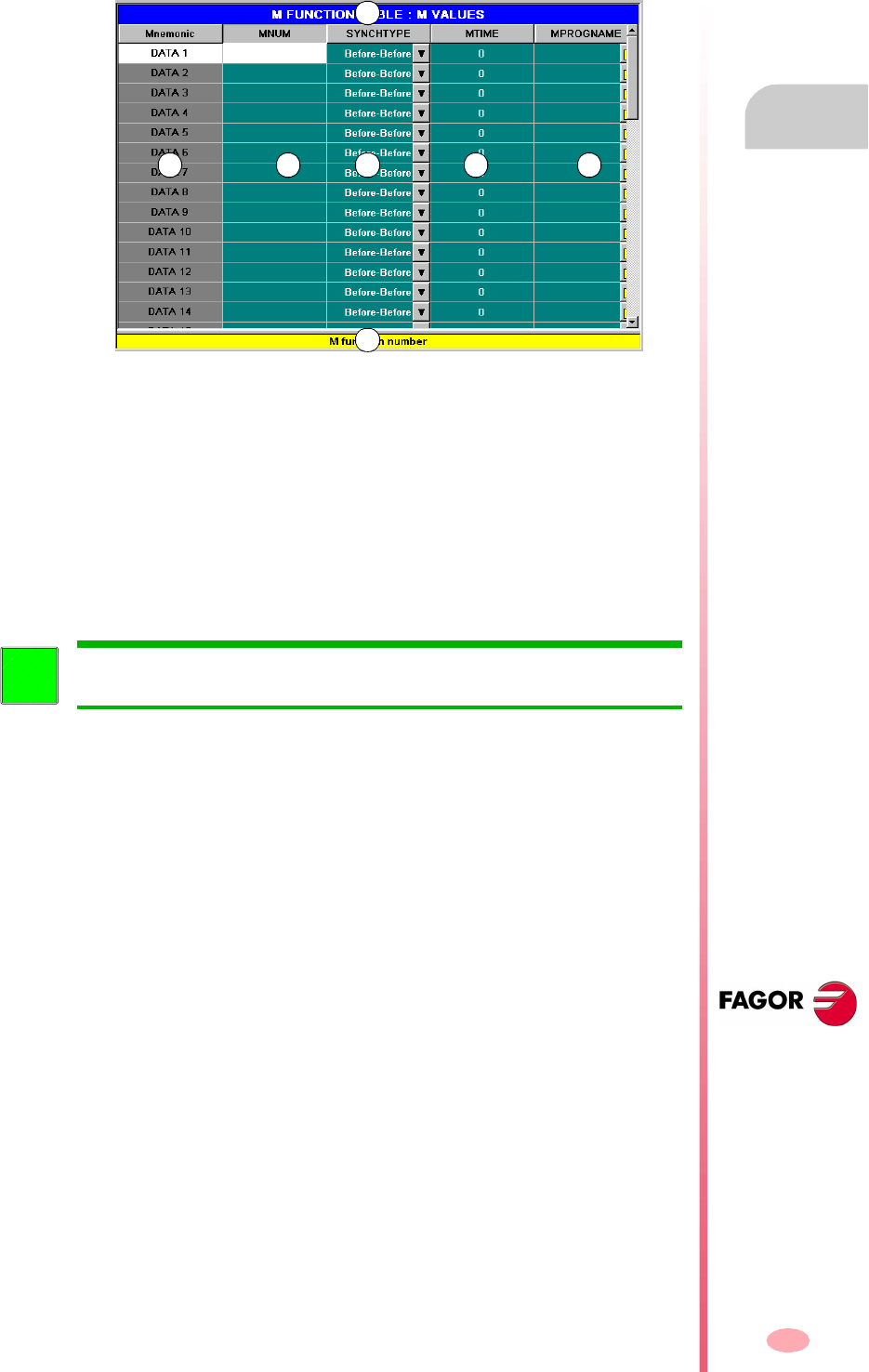
Operating manual
CNC 8070
MACHINE PARAMETERS
Parameter table description
12.
(SOFT V03.0X)
261
12.2.1 "M" function setting table
This table is accessed using the M-function machine parameter "DATA" and it has
the following structure:
A. Name of the selected machine parameter table.
B. Order number.
C. List of user defined "M" functions.
D. Type of synchronism.
E. Time for execution time estimate.
F. Associated subroutine.
G. Parameter description.
The section on "12.3.1 Data editing and validation" in this chapter shows how to
edit the parameters of the tables.
A
B C D E F
G
To obtain further information about the data appearing in the table, refer to the
chapter on machine parameters of the Installation and Start-up Manual.
i
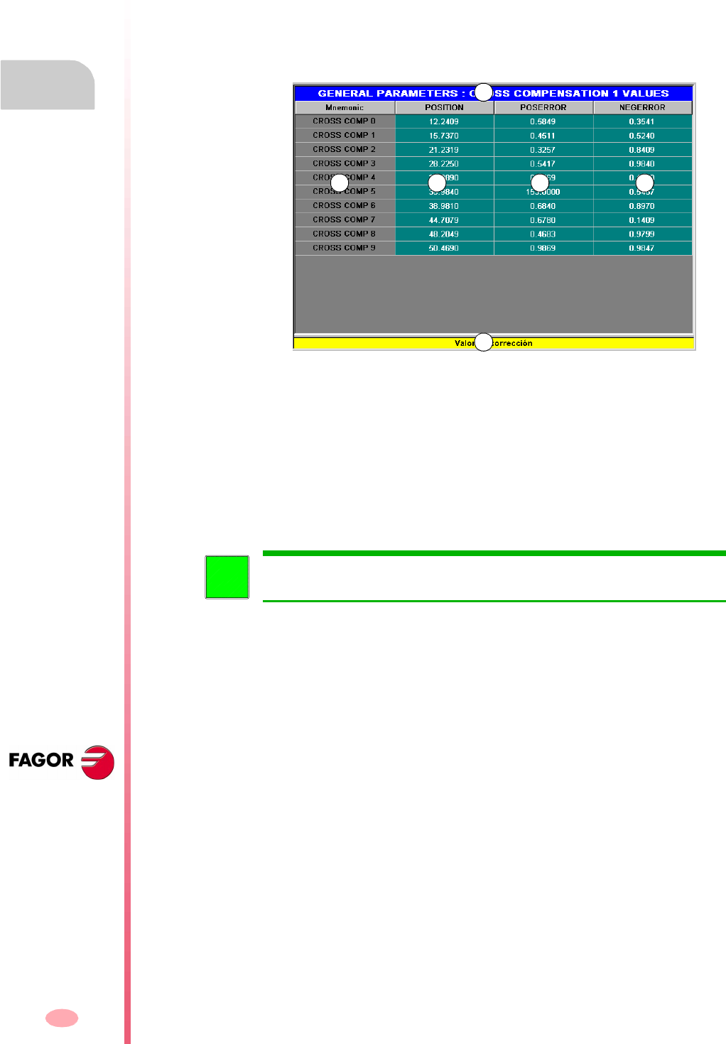
Operating manual
CNC 8070
12.
MACHINE PARAMETERS
Parameter table description
(SOFT V03.0X)
262
12.2.2 Compensation table
There are two types of compensation table:
•Leadscrew error compensation, which is accessed with the axis machine
parameter "COMPENSATION".
•Cross compensation, which is accessed with the general machine parameter
"CROSS COMP".
These compensation tables have the following structure:
A. Name of the selected machine parameter table.
B. Compensation point.
C. User defined axis position.
D. Amount of error to compensate in the positive direction.
E. Amount of error to compensate in the negative direction.
F. Parameter description.
The section on "12.3.1 Data editing and validation" in this chapter shows how to
edit the parameters of the tables.
A
B C D E
F
To obtain further information about the data appearing in the table, refer to the
chapter on machine parameters of the Installation and Start-up Manual.
i
Operating manual
CNC 8070
MACHINE PARAMETERS
Operations with tables
12.
(SOFT V03.0X)
263
12.3 Operations with tables
12.3.1 Data editing and validation
Use the softkey menu to select the desired machine parameter table. To edit the table
data, proceed as follows:
1. Use the cursor to select the parameter whose value is to be set.
2. Key in the desired value. If [SUP] is pressed, the parameter will assume the default
value.
3. Press [ENTER] to accept the new value or [ESC] to ignore the new value and
recover the previous one.
Parameter types
Certain parameters can only assume specific values. These parameters will be
identified as follows.
Depending on the type of values they can assume, they will be defined as follows:
•If the parameter may assume a value between specific limits, enter the desired
value.
If the value exceeds those limits, the parameter will assume its default value.
•If the parameter contains a list of options, press [ENTER] to display the drop list
and select one of those options.
•If the parameter refers to a file, press [ENTER] and the CNC will show the list of
available files.
Data validation.
To validate certain parameters, restart the CNC. These parameters will be identified
with the following symbol next to their name:
The parameter has a list of options.
The parameter refers to a file.
After editing or modifying the table data, the new values must be validated so they
are assumed by the CNC. To validate the data, press the VALIDATE icon.
Restarting the CNC required.
Operating manual
CNC 8070
12.
MACHINE PARAMETERS
Operations with tables
(SOFT V03.0X)
264
12.3.2 Save and recall tables
Saving a table
It may be used to save the table data, in ASCII format, in a file.
Use the softkey menu to select the table whose data is to be saved. If no table is
selected, all the data of all the tables will be saved.
To save the table data, proceed as follows:
1. Select the destination folder.
2. Define the file name at the bottom window. To replace an existing file, select it from
the list.
3. Press [ENTER] to save the file or [ESC] to return to the tables without saving the
file.
The files are saved with the extension *.MP.
Recall a table
It may be used to restore the table data, in ASCII format, from a file.
Use the softkey menu to select the table whose data is to be recalled (restored). If
no table is selected, all the data of all the tables will be recalled.
To recall the table data, proceed as follows:
1. Select the folder containing the file.
2. Select the file from the list or write its name in the bottom window.
3. Press [ENTER] to recall the data or [ESC] to return to the tables without recalling
the data.
After selecting the table whose data is to be saved, press the SAVE icon and the CNC
shows a list with the tables that are already saved.
Keys for selecting a data file
To switch windows.
To close and open a folder submenu.
To move the cursor thru the elements of the window.
To save the new program.
To cancel the selection and close the programs listing.
After selecting the table whose data is to be restored, press the LOAD icon and the
CNC shows a list with the tables that are already saved.
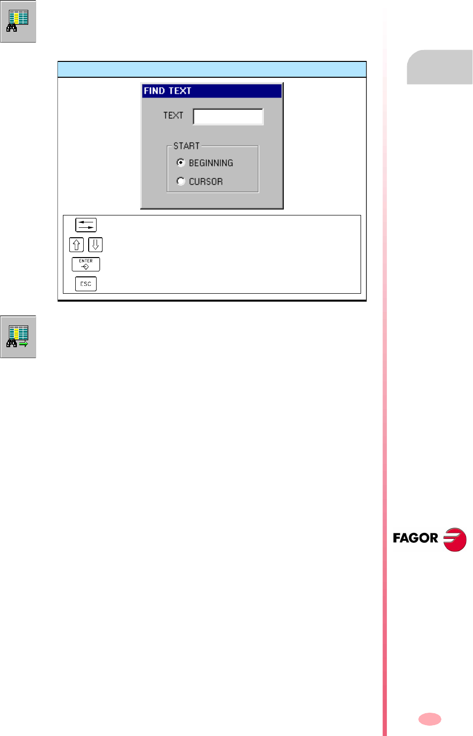
Operating manual
CNC 8070
MACHINE PARAMETERS
Operations with tables
12.
(SOFT V03.0X)
265
12.3.3 Find text
It is used to find text or a value in the table.
To perform the search, press the FIND icon and the CNC will show a dialog box
requesting the text or value to be searched. It is also possible to select whether the
search must start at the beginning of the table or at the current cursor position.
Find text
To move the cursor through the elements of the list.
It selects an option from a group.
To start the search.
To cancel the search and close the dialog box.
To start the search, press [ENTER] and the cursor will position on the text found.
Pressing this FIND icon again will allow repeating the search or defining a new one.

Operating manual
CNC 8070
12.
MACHINE PARAMETERS
Operations with tables
(SOFT V03.0X)
266

267
CNC 8070
(SOFT V03.0X)
13
SETUP ASSISTANCE
The set of utilities of the setup assistance is meant to speed up and simplify the
machine setup procedure. The setup assistance offers the following utilities.
•The oscilloscope.
•The circularity (roundness) test.
•The bode diagram.
It must be borne in mind that these utilities are assistance tools that only show the
system's response to the various adjustments; it is always up to the technician to
choose the best adjustment.
The oscilloscope
The oscilloscope is an assistance tool for adjusting the CNC and the drives. This utility
can graphically show 4 previously selected variables, modify their values and check
the different responses of the system.
Using the oscilloscope, it is possible to edit the CNC's machine parameters that affect
the adjustment; it is also possible to modify at the Sercos
®
drives the variables that
have writing permission. In any case, a protection password is required for modifying
the CNC's machine parameters or the drive's variables.
The Bode diagram
The Bode diagram is an assistance tool for adjusting the CNC and the drives. This
utility may be used to obtain the Bode diagram of the response amplitude depending
on the frequency of the input signal.
With this tool, it is possible to insert a sinusoidal signal into an axis, so that changing
the frequency and analyzing the response provides the behavior of the axes at
different frequencies and will give the user an idea of how it behaves with any signal.
This diagram may be used to check the system's gain, the bandwidth and the
mechanical resonance. All this helps achieve the proper adjustment of the loops,
analyze mechanical problems and check the final features.
Operating manual
CNC 8070
13.
SETUP ASSISTANCE
(SOFT V03.0X)
268
The circularity (roundness) test
This tool helps improve and adjust the axis reversal peak, an effect that appears when
the axes reverse their moving direction. With this utility, a circle may be executed with
the axes and graphically show the result. This graphic shows the difference between
the actual (real) coordinate obtained from the feedback device and the theoretical
coordinate calculated at each point.
The same screen showing the graphics also shows the machine parameters that
affect the movement reversal. These parameters may be modified while running the
test, thus being possible to evaluate the response of the system to these changes
and optimize the adjustment on the go.
Selection of setup assistance
The different tools are accessed from the horizontal softkey menu.
Setup assistance may be accessed either using the user key if it has been set
accordingly or from the task window (by selecting the Tuni ng option). The task window
may be accessed with key combination [CTRL]+[A].
The oscilloscope.
The Bode diagram.
The circularity (roundness) test.
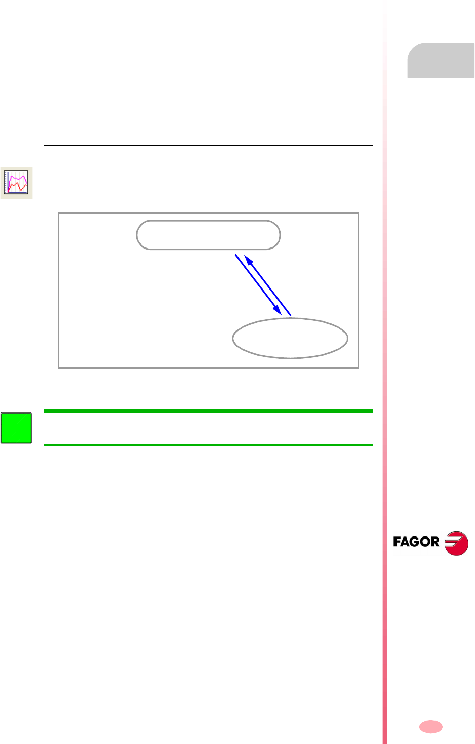
Operating manual
CNC 8070
SETUP ASSISTANCE
Oscilloscope
13.
(SOFT V03.0X)
269
13.1 Oscilloscope
The oscilloscope is an assistance tool for adjusting the CNC and the drives. This utility
can graphically show 4 previously selected variables, modify their values and check
the different responses of the system.
Using the oscilloscope, it is possible to edit the CNC's machine parameters that affect
the adjustment; it is also possible to modify at the Sercos
®
drives the variables that
have writing permission. In any case, a protection password is required for modifying
the CNC's machine parameters or the drive's variables.
The oscilloscope is an assistance tool that only shows the response of the system
to the various settings (adjustments); it is up to the technician to choose the best
adjustment.
How to access the oscilloscope
This utility is one of the features of setup assistance. Together with the circularity test
and the bode diagram, it helps speed up and simplify the machine setup process.
The oscilloscope may be accessed from the softkey menu for setup assistance.
Setup assistance
Oscilloscope function
The oscilloscope function requires Sercos communication and a drive version
V06.01 or later. Otherwise, the CNC will show the error "Access denied".
i
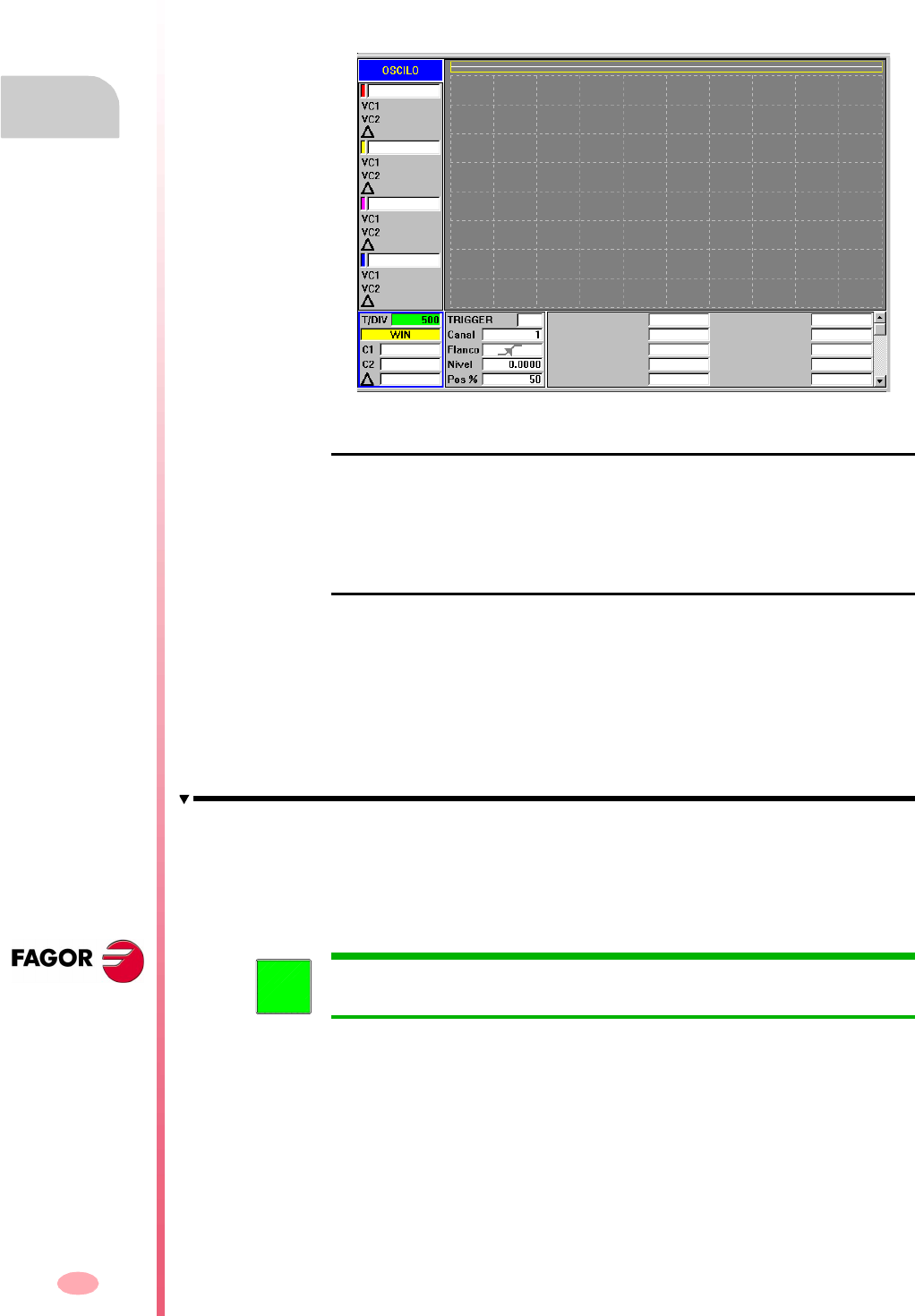
Operating manual
CNC 8070
13.
SETUP ASSISTANCE
Oscilloscope
(SOFT V03.0X)
270
13.1.1 Interface description
The screen of the oscilloscope function looks like this, with two clearly different parts.
The left side and the lower side show the data of the variables to be shown, the trigger
data, the time base and the parameters that may be acted upon. The top right side
shows the variables graphically.
The graphics window
It is the area showing a graphic representation of the selected variables. For each
variable, it shows the scale used to draw it.
The data area
It is the area where the user interacts with the system. It allows defining the graphic
environment, the variables to be display, the trigger configuration, the time base
configuration and the values of the parameters involved.
Some of this data may also be defined at the configuration screen. See
"Configuration screen" on page 275.
Variables to be displayed
It is the area where the user select the variables to be shown in the graphics window.
Up to 4 variables may be displayed at the same time.
This window does not allow selecting the color of each variable being displayed.
To change the color of any variable, it must be done at the configuration
screen.
i

Operating manual
CNC 8070
SETUP ASSISTANCE
Oscilloscope
13.
(SOFT V03.0X)
271
Trigger data
In this area, the user may select the trigger conditions. The options offered by this
trigger data area are:
Trigger
It indicates when the data capture begins.
If not selected, the data capture begins as soon as the user gives the command to
begin. The "Flank", "Level" and "Position" data are ignored.
If selected, the trigger condition must be specified with the "Flank", "Level" and
"Position" data.
Channel
It indicates which variable or channel (CH1, CH2, CH3, CH4) is to be used as
reference or trigger condition.
Flank
It may be up-flank (leading edge) or down-flank (trailing edge).
It is taken into account when trigger has been selected.
Trigger level
It sets the value to be assumed by the variable to start capturing data.
It is taken into account when trigger has been selected.
Position (%)
It is taken into account when Trigger has been selected.
It is defined as a percentage, between 0% and 100%. It indicates the number of
samples to be taken before the Trigger. For example, a 10% position indicates that
10% of the total number of programmed samples will be taken before the Trigger and
the remaining 90% after that instant.
The Trigger condition is evaluated after gathering the indicated % of samples. If the
position is defined as 50% and the Trigger condition takes place after taking 10% of
the samples, it is ignored until capturing 50% of the samples.
Machine parameters to be set
In this area of the data window, it is possible to directly change the values of up to
20 machine parameters to be adjusted.
Operating manual
CNC 8070
13.
SETUP ASSISTANCE
Oscilloscope
(SOFT V03.0X)
272
Softkey menu
Horizontal softkey menu
The horizontal softkey menu offers the following options:
Softkey CONFIG
It access the configuration screen. It may be used to define which variables will
be displayed, their scale, colors, time base, the Trigger, the trigger condition, the
parameters to act upon, etc.
Softkey DATA
It accesses the data processing submenu. This submenu serves to save and load
the captured trace as well as the configuration defined for it.
It may also be used to send data of the captured trace out to printer or to a file.
Softkey OVERLAP CHANNELS
Wit this option, several channels may be overlapped.
When this option is selected, the softkey color changes to red.
Softkey AUTOSCALE
When autoscaling a channel, the system determines the proper vertical scale and
offset so the signal appears as enlarged as possible inside its graphic area.
Enlarge screen
With this option, it is possible to enlarge the graphics window to the left, using the
area that shows the variables to be displayed. Pressing the same softkey returns
the screen to the previous size.
Softkey FREEZE SCREEN
The display is "frozen" without interrupting the data capture. When this option is
selected, the softkey shows "Resume".
This softkey only appears on the horizontal softkey menu if the capture is in
continuous mode. To set the capture in continuous mode, change the "mode"
option of the configuration screen.
Softkey BEGIN CAPTURE
Start taking data to show it graphically.
When this option is selected, the softkey shows "Stop".
i
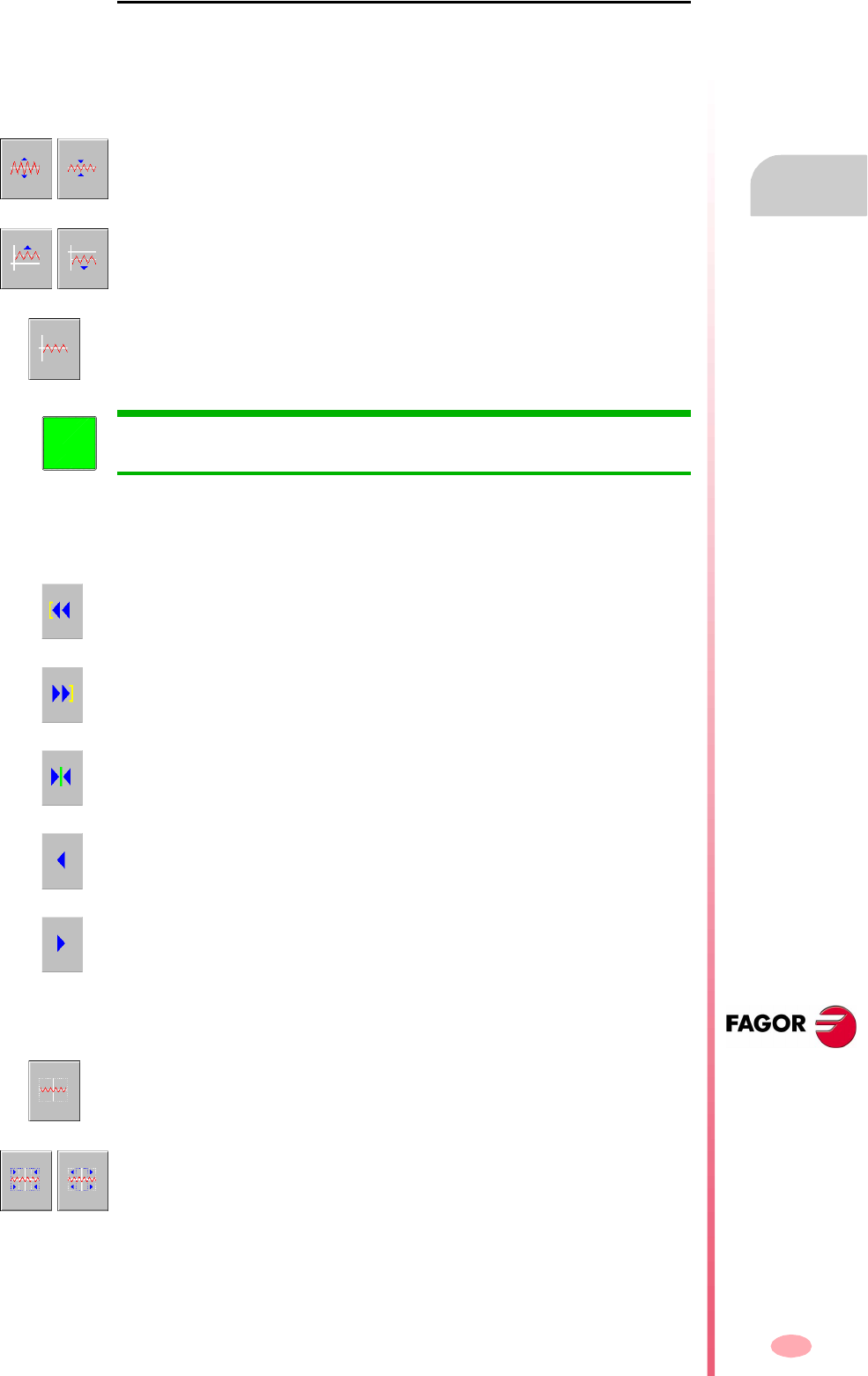
Operating manual
CNC 8070
SETUP ASSISTANCE
Oscilloscope
13.
(SOFT V03.0X)
273
Vertical softkey menu
Depending on which data has the focus, the vertical softkeys show different options.
Focus on a variable of a channel
When the focus is on any of the variables, the vertical softkeys will be:
Focus on the "WIN" field
With win, it shows the oscilloscope window where it is. When the focus is on this field,
the vertical softkeys will be:
Focus on the "T/Div" field
When the focus is on the "T/Div" field, the following softkeys will appear.
The scale of the graphic may be changed with the "scale" softkeys. The new scale
value will appear on the graphic next to the corresponding variable.
The graphics of the desired channel may be moved up and down using the offset
softkeys.
This softkey may also be used to center the graphics.
When the focus is on any of the variables, a new variable name may be either
keyed in or selected without having to go to "CONFIG".
i
It takes the window to the beginning.
It takes the window to the end.
It takes the window to the trigger. If there is no trigger, it will go to the center of the
window.
Moves the window to the left.
Moves the window to the right.
Using the autoscale softkey, the oscilloscope selects the right time scale so the signal
appears as large as possible inside its corresponding graphic area.
It increases or decreases the time scale.
Operating manual
CNC 8070
13.
SETUP ASSISTANCE
Oscilloscope
(SOFT V03.0X)
274
Focus on the "C1" or "C2" field
Cursors "C1" and "C2" may be used to analyze each signal of the last data capture.
These two cursors may be used to obtain the position in milliseconds of each signal
and the time difference between them "∆".
When the focus is on one of the fields "C1" or "C2", the following vertical softkeys will
appear.
Focus on the "parameter name" field
As with variables, by selecting the various parameters, it is possible to change their
names and values.
When pressing "Enter" after changing the name of a parameter, use the up, down,
left and right arrow keys to move the focus to the next field to change the value of
that parameter. After changing the parameter value and pressing "Enter", the focus
does not go on to the next field. Use the arrow keys to go on to the next parameter.
When the focus is on this field, the 4 vertical softkeys will be:
Takes the cursor to the beginning.
Takes the cursor to the end.
Takes the cursor to the trigger. If there is no trigger, it will go to the center of the window.
Moves the cursor to the left.
Moves the cursor to the right.
It increases the value of the parameter in the amount indicated on the configuration
screen.
It decreases the value of the parameter in the amount indicated on the configuration
screen.
It resets the parameter to its default value.
It validates the value given to the parameter.
From the "CONFIG" mode, a screen may be accessed where it is possible to
define the list of parameters to be displayed.
i
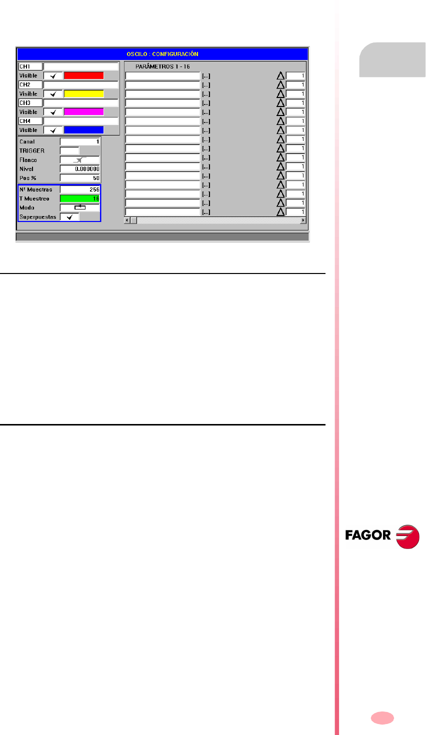
Operating manual
CNC 8070
SETUP ASSISTANCE
Oscilloscope
13.
(SOFT V03.0X)
275
13.1.2 Configuration screen
The configuration screen may be accessed with the horizontal softkey "CONFIG".
This screen looks like this with two clearly different areas. The left side shows the data
of the variables to be displayed, the trigger data and the time base. The right side
shows the parameters to be acted upon and the amount to increase/decrease the
values of those parameters.
Selection of the variables to be displayed, trigger and time base
It is the area where the user selects the variables to be displayed at the graphics
window, the trigger options and the time base. Up to 4 variables may be displayed
at the same time.
When typing the name of any variable incorrectly, the CNC will show the error "Access
denied".
Besides the trigger data and the base time, this window may be used to select the
color used to display the variable and whether it will be visible or not.
Parameter selection and increase/decrease
It is the area where the user selects the parameters upon which to act. To the right
of each parameter, there is a square used to increase/decrease of its value.
This way, when the focus is on the value of a variable on the main screen, pressing
the vertical softkey "V+" will increase the parameter value in the amount set on the
configuration screen.
By default, the increase/decrease value of a parameter is initialized to 1.
Operating manual
CNC 8070
13.
SETUP ASSISTANCE
Oscilloscope
(SOFT V03.0X)
276
13.1.3 Configure and execute the oscilloscope function
In the oscilloscope mode, from a single screen, it is possible to select the variables
to be analyzed, the trigger conditions and the machine parameters of the CNC or the
drive that may be modified.
Operating procedure
Execute a part-program to move the axis or axes to be adjusted. Once the program
is running, go into the adjustment mode and access the oscilloscope function.
Define the variables to be analyzed, the trigger conditions and the machine
parameters of the CNC or the drive that may be modified.
Data capture and later analysis of the data.
Once the data capture has been interrupted or completed, it is possible to analyze
the signals and modify the parameters that have been previously selected in order
to improve the machining conditions.
Repeat the capture, the analysis and the modification of parameters until obtaining
the best machining conditions.
Recommendations
Execute endless repetitive movements. After adjusting the axes individually, readjust
the interpolating axes together.
The user must determine which is the best adjustment, the oscilloscope function is
just an assistance tool.
Operation
To enter or modify a data on the screens, it must be selected; in other words, it must
have the editing focus on it.
Use the [©] [ª] keys to select another editable data or field. It is a rotary selection,
if the [©] key pressed when the first element of the screen is selected, the focus goes
to the last element whereas if the [ª] is pressed when the last element is selected,
the focus goes to the first element.
Not all the fields are editable, only the ones that may be selected can be edited, those
having the focus. There are two types of editable fields:
Editable values:
They may be assigned a value, either a two-digit number or alphanumeric
(numbers and letters). Before validating the data, it is checked out and if it is not
correct, it will not be accepted and a warning message will be issued.
Values that may be selected:
The possible data are fixed one of them must be selected. Use the [¨] [§] keys
to see the possible values. For this type of values that are icons, the [SPACE] key
has the same effect as the [¨] key.
When capturing 1 or 2 variables of the same drive, the capture will be done
by the drive itself and the CNC will be in charge of drawing the results.
When capturing more than 2 variables or 2 variables from different drives, in
order to synchronize data, the capture will be done by the CNC and the
sampling period will be the CNC's cycle time.
i
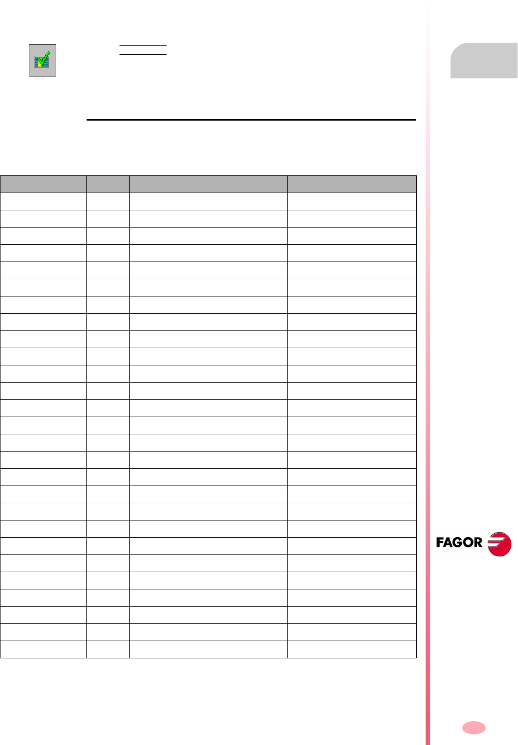
Operating manual
CNC 8070
SETUP ASSISTANCE
Oscilloscope
13.
(SOFT V03.0X)
277
13.1.4 Machine parameter editing
Here is a list of machine parameters and variables of the drive that may be modified
from the oscilloscope.
The new values are assumed by the CNC after pressing [ENTER] and they are
maintained until the unit is turned off. Once the setup is completed, the changes must
be saved so they can be effective next time the CNC is turned on.
Axis or spindle machine parameters that may be edited
The table indicates the parameters that will be assumed at the beginning of the next
block. For this to be so, the instruction "#SYNC POS" must be programmed after each
motion block.
If the machine parameters are protected, when accessing any of them, the CNC will
display a window requesting a password.
Use the VALIDATE softkey to save the data. The CNC saves the new values in the
CNC tables and/or in the drive tables accordingly.
CNC Drive Associated variable Update
PRELOAD MPG.PRELOAD[tandem] Immediate
PRELFITI MPG.PRELFITI[tandem] Immediate
TPROGAIN MPG.TPROGAIN[tandem] Immediate
TINTIME MPG.TINTIME[tandem] Immediate
TCOMPLIM MPG.TCOMPLIM[tandem] Immediate
INPOSW MPA.INPOSW.[set].axis Immediate
BACKLASH PP58 MPA.BACKLASH.[set].axis Immediate
G00FEED MPA.G00FEED.[set].axis Beginning of next block
MAXVOLT MPA.MAXVOLT.[set].axis Immediate
PROGAIN PP104 MPA.PROGAIN.[set].axis Immediate
FFGAIN PP216 MPA.FFGAIN.[set].axis Immediate
MANFFGAIN PP216 MPA.MANFFGAIN.[set].axis Immediate
ACFWFACTOR MPA.ACFWFACTOR.[set].axis Immediate
ACFGAIN PP217 MPA.ACFGAIN.[set].axis Immediate
MANACFGAIN PP217 MPA.MANACFGAIN.[set].axis Immediate
LACC1 MPA.LACC1.[set].axis Beginning of next block
LACC2 MPA.LACC2.[set].axis Beginning of next block
LFEED MPA.LFEED.[set].axis Beginning of next block
ACCEL PP42 MPA.ACCEL.[set].axis Beginning of next block
DECEL PP42 MPA.DECEL.[set].axis Beginning of next block
ACCJERK MPA.ACCJERK.[set].axis Beginning of next block
DECJERK MPA.DECJERK.[set].axis Beginning of next block
ESTDELAY MPA.ESTDELAY.[set].axis Immediate
SERVOOFF MPA.SERVOOFF.[set].axis Immediate
MINANOUT MPA.MINAOUT[.set].axis Immediate
BAKANOUT PP2 MPA.BAKANOUT.[set].axis Immediate
BAKTIME PP3 MPA.BAKTIME.[set].axis Immediate
Operating manual
CNC 8070
13.
SETUP ASSISTANCE
Oscilloscope
(SOFT V03.0X)
278
Variables that may be modified at the Sercos drive
Besides the parameters shown in the previous table, the user may access any
variable having a writing permission if he knows its name. To do this, use the following
nomenclature:
Indicate the axis, the name of the parameter and the set separated by a period.
When modifying any parameter of the previous table, the change is effective
immediately without having to reset or restart the unit even when there is a program
in execution.
The drive parameters modified with this method are functional immediately, but these
values will be lost when the drive is turned off. Use the "Save to flash" option to
maintain the modified values of those machine parameters.
Drive Name Update
CP1 CP1.axis Immediate
CP2 CP2.axis Immediate
CP3 CP3.axis Immediate
CP30 CP30[set].axis Immediate
CP31 CP31[set].axis Immediate
CP32 CP32[set].axis Immediate
NP1 NP1.axis Immediate
RP1 RP1.axis Immediate
RP2 RP2.axis Immediate
RP3 RP3.axis Immediate
RP4 RP4.axis Immediate
RP51 RP51.axis Immediate
RP52 RP52.axis Immediate
RP53 RP53.axis Immediate
RP54 RP54.axis Immediate
SP1 SP1[set].axis Immediate
SP2 SP2[set].axis Immediate
SP50 SP50.axis Immediate
SP51 SP51.axis Immediate
TP10 TP10.axis Immediate
TP11 TP11.axis Immediate
TP12 TP12.axis Immediate
TP13 TP13.axis Immediate
TP14 TP14.axis Immediate

Operating manual
CNC 8070
SETUP ASSISTANCE
Oscilloscope
13.
(SOFT V03.0X)
279
Saving, loading and resetting the condigurations
When defining a new configuration of variables to be displayed and parameters
modified at the oscilloscope, the system allows saving that configuration into a file.
Likewise, the system allows loading a configuration that was saved previously or
resetting the current configuration.
Save
To save the current configuration, go to the configuration screen and press the "Save"
softkey.
After this, a new screen appears showing the available configurations with the focus
on the last one.
Also, it is possible to rename the new configuration whose extension must be "osc".
Load
To load a previously saved configuration, go to the configuration screen and press
the "Load" softkey.
Then, a new screen appears showing a list of previously saved configurations, being
possible to select any of them.
Reset
Pressing the "Reset" softkey of the configuration screen deletes or initializes the
current configuration. There are neither variables nor parameters selected and the
rest of conditions (colors, trigger, etc.) assume the values assigned by default.
Operating manual
CNC 8070
13.
SETUP ASSISTANCE
The Bode diagram
(SOFT V03.0X)
280
13.2 The Bode diagram
The Bode diagram is an assistance tool for adjusting the CNC and the drives. This
utility may be used to obtain the Bode diagram of the response amplitude depending
on the frequency of the input signal.
With this tool, it is possible to insert a sinusoidal signal into an axis, so that changing
the frequency and analyzing the response provides the behavior of the axes at
different frequencies and will give the user an idea of how it behaves with any signal.
This diagram may be used to check the system's gain, the bandwidth and the
mechanical resonance. All this helps achieve the proper adjustment of the loops,
analyze mechanical problems and check the final features.
The Bode diagram is an assistance tool that only shows the response of the system
to the various settings (adjustments); it is up to the technician to choose the best
adjustment.
How to access the Bode diagram
The Bode diagram may be accessed from the softkey menu for setup assistance.
Setup assistance
Bode
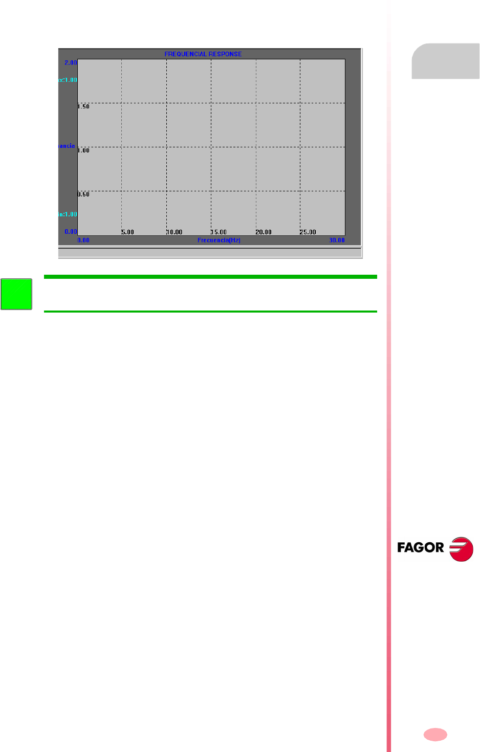
Operating manual
CNC 8070
SETUP ASSISTANCE
The Bode diagram
13.
(SOFT V03.0X)
281
13.2.1 Interface description
The Bode screen looks like this with a single area for the graphics window that shows
the Bode diagram.
Besides the Bode diagram, the graphics window shows in dark blue the maximum
and minimum gains, in black the gain and frequency values of each line of the grid
and in light blue the maximum and minimum values obtained when analyzing the axis
The colors mentioned earlier for the different data shown on the screen are
the default ones. Use the "Options" softkey to change them.
i
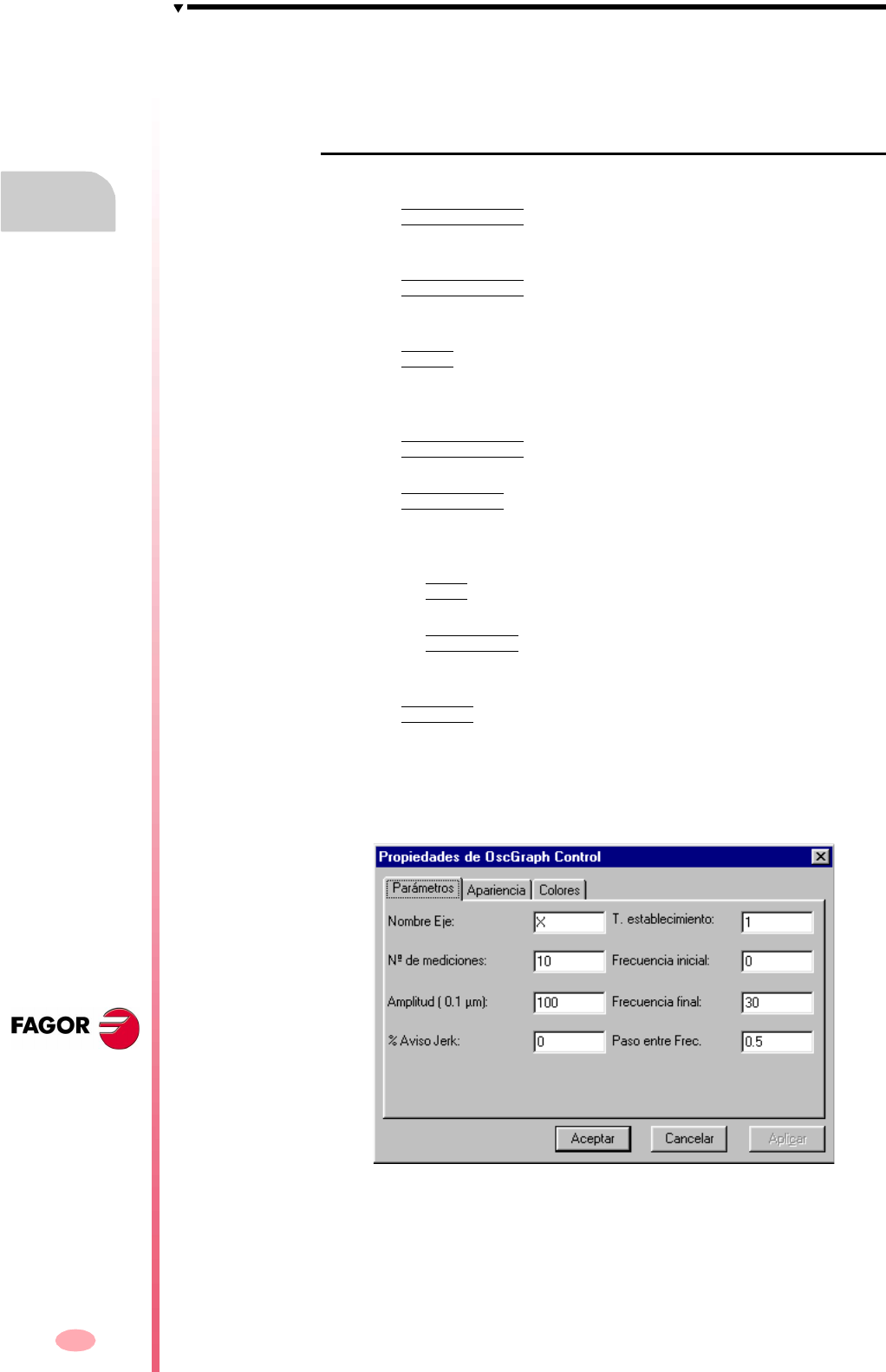
Operating manual
CNC 8070
13.
SETUP ASSISTANCE
The Bode diagram
(SOFT V03.0X)
282
Softkey menu
There are some horizontal and vertical softkeys for changing the various options:
Horizontal softkey menu
The horizontal softkey menu offers the following options:
Softkey ANALYZE AXIS
This softkey begins the estimation of the frequency response of the selected axis
by means of the options.
Softkey END ANALYSIS
This softkey ends the estimation of the frequency response of the selected axis
by means of the options.
Softkey PRINT
This softkey serves to send the Bode graph as a bitmap out to a printer or to a
file. This makes it possible to print the screen. The border is removed when
printing the screen.
Softkey CLEAR SCREEN
This softkey initializes the graphics.
Softkey DIMENSIONS
This softkey serves to modify the maximum and minimum gains represented in
the graphics. Pressing this options displays a new menu with two horizontal
softkeys.
•Softkey EDIT
This softkey serves to edit the limit values.
•Softkey AUTOMATIC
This softkey adjusts the limits to the maximum and minimum values obtained
from analyzing the axis.
Softkey OPTIONS
This softkey serves to configure the data for the analysis and the way the graphics
will look. This option gives access to the following configuration windows:
1. Parameters window:
This window may be used to configure the data used to analyze the axes.
These data are:
Axis name: Name of the axis to be analyzed.
Number of measurements: Number of measurements for each frequency (it
shows the average between the maximum and the minimum response
amplitudes of each repetition)
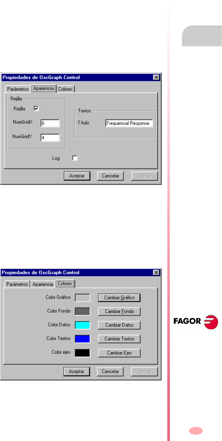
Operating manual
CNC 8070
SETUP ASSISTANCE
The Bode diagram
13.
(SOFT V03.0X)
283
Amplitude: Amplitude of the sinusoidal signal that is generated.
% Jerk warning: Factor over the jerk parameter to issue the "jerk exceeded"
warning.
Settle T.: Waiting time from when it starts generating the signal for each
frequency until the data is being taken into account.
Initial frequency: Frequency from which the analysis begins.
Final Frequency: Last frequency being analyzed.
Pitch between Freq: The frequency being analyzed is incremented with this
pitch (step) from the initial frequency until exceeding the final one thus
completing the analysis.
2. Aspect window:
This window serves to configure the way the graphics will look.
The fields that may be configured are:
Grid: Display/Hide the grid.
NumGridX: Number of horizontal lines of the grid.
NumGridY: Number of vertical lines of the grid.
Title: Title of the graph.
Log: Gain in decibels and logarithmic representation in frequency.
3. Colors window:
This window serves to configure the colors of the graphics.
Graphics color: Background color of the graph.
Background color: Background color of the control.
Data color: Color of the captured data.
Text color: Text color of the graph.
Operating manual
CNC 8070
13.
SETUP ASSISTANCE
The Bode diagram
(SOFT V03.0X)
284
Axis color: Grid color.
Vertical softkey menu
When defining a new configuration, the system permits saving that configuration in
a file. Likewise, the system permits loading a previously saved configuration.
The vertical softkey menu offers the options to save and load configurations:
Softkey SAVE
Press the "save" softkey to save the current configuration.
After this, a new screen appears showing the available configurations.
It is also possible to rename the new configuration.
Softkey LOAD
Press the "load" softkey to load a previously saved configuration.
Then, a new screen appears showing a list of previously saved configurations,
being possible to select any of them.
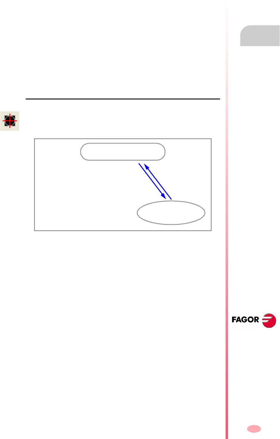
Operating manual
CNC 8070
SETUP ASSISTANCE
The circularity (roundness) test
13.
(SOFT V03.0X)
285
13.3 The circularity (roundness) test
This tool helps improve and adjust the axis reversal peak, an effect that appears when
the axes reverse their moving direction. With this utility, a circle may be executed with
the axes and graphically show the result. This graphic shows the difference between
the actual (real) coordinate obtained from the feedback device and the theoretical
coordinate calculated at each point. This difference is shown projected radially.
The same screen showing the graphics also shows the machine parameters that
affect the movement reversal. These parameters may be modified while running the
test, thus being possible to evaluate the response of the system to these changes
and optimize the adjustment on the go.
The circularity (roundness) test diagram is an assistance tool that only shows the
response of the system to the various settings (adjustments); it is up to the technician
to choose the best adjustment.
How to access the circularity (roundness) test
The circularity (roundness) test may be accessed from the softkey menu for setup
assistance.
Setup assistance
Circularity (roundness)
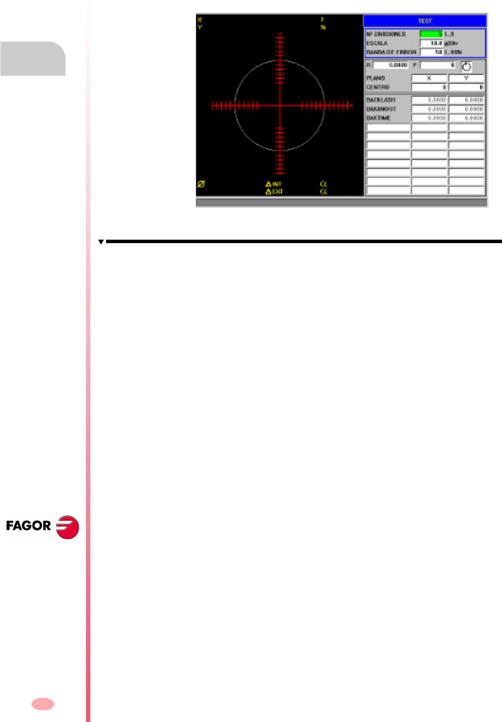
Operating manual
CNC 8070
13.
SETUP ASSISTANCE
The circularity (roundness) test
(SOFT V03.0X)
286
13.3.1 Interface description
The screen of the circularity test looks like this, with two clearly different parts. A
graphics window that shows the result of the test and a data area for interacting with
the system.
The graphics window
It is the area that shows, graphically, the result of the test.
The graphic shows the two moving axes and the theoretical circle of the interpolation
that will be carried out. As the test is being run, the positioning error at each point
is drawn on the circle. This error is shown projected radially.
Superimposed on the graphics, it shows the following additional data that is updated
by the CNC.
•The real coordinates of the axes.
•Programmed feedrate and % applied.
•Diameter of the displayed circle.
•Maximum and minimum error over the theoretical radius and angular position
where it has been detected.

Operating manual
CNC 8070
SETUP ASSISTANCE
The circularity (roundness) test
13.
(SOFT V03.0X)
287
The data area
It is the area where the user interacts with the system. It offers a set of data for defining
the graphic environment, the subroutine that will be used to generate the machine
movement and the machine parameters involved in the adjustment. Selecting one
of the data frames the group of parameters it belongs to.
Graphic environment data to be configured
•Number of divisions on both sides of the theoretical circle.
•Scale or value in microns of each division.
•Error margin. Percentage of the area that is occupied by the error margin
(divisions area).
See "Machine parameter editing" on page 277.
Movement subroutine
The circular interpolation is carried out using a subroutine. See "Define and execute
the movement subroutine" on page 291.
The following data is taken into consideration when executing the subroutine.
•Plane where the circle is executed.
•Circle center coordinates.
•Circle radius.
•Programmed feedrate.
•Turning direction.
Parameters to be set
To make the adjustment, it is possible to change the CNC machine parameters or the
drive machine parameters involved. See "Adjustment of the machine parameters
involved" on page 293.
It is possible to interact with up to 11 different machine parameters. Some of these
parameters are always visible, but some may be defined at will. For each parameter,
it shows its value on each axis of the work plane.
To see the whole list of parameters that may be defined, see section
"13.3.8 Machine parameters that may be modified".
Operating manual
CNC 8070
13.
SETUP ASSISTANCE
The circularity (roundness) test
(SOFT V03.0X)
288
Softkey menu
Horizontal softkey menu
The horizontal softkey menu offers the following options.
Softkey SIMPLE.
It captures the data of a full circle.
Softkey CONTINUOUS.
It captures data continuously.
Softkey STOP
It stops the data capture. This softkey is shown when data capture is running.
Softkey CLEAR
It deletes the graphic representation. It may be done while the capture is running;
in that case, it goes on with the graphic representation.
Softkey LOAD.
It loads a previously saved configuration.
Softkey SAVE.
It saves the configuration defined.
Vertical softkey menu
The vertical softkey menu offers the following options.
This softkey only stops the data capture. It does not stop the movement of the
axes. To stop the movement of the axes, press the [STOP] key of the operator
panel.
i
Softkey VALIDATE.
It saves the values of the machine parameters in the tables of the CNC and/or
the drive accordingly.
When changing the values of the machine parameters, the changes are effective
immediately. However, these changes are maintained only during the current
session of the CNC; i.e. until the unit is turned off. On power-up, it assumes the
values stored in the tables.
Softkey INITIALIZE.
It resets the window data to its default values.

Operating manual
CNC 8070
SETUP ASSISTANCE
The circularity (roundness) test
13.
(SOFT V03.0X)
289
13.3.2 Configuring and executing the circularity (roundness) test
The process consists in executing a circle with the axes of the machine and verifying
it on its graphic representation. The graphic shows the difference between the actual
(real) coordinate obtained from the feedback device and the theoretical coordinate
calculated in that point. This difference is shown projected radially.
The interpolation of the machine axes and the point capture for the graphics are
initiated separately. The data capture is handled from the softkey menu whereas the
movement of the axes is controlled from the operator panel.
The adjustment process is repeated until obtaining the best adjustment of the axes.
The circularity (roundness) test diagram is an assistance tool that only shows the
response of the system to the various settings (adjustments); it is up to the technician
to choose the best adjustment.
How to execute the circularity (roundness) test
Basically it is done as follows. Each of these points is described in more detail in the
indicated chapter.
The configuration used may be saved in a file for later.
1. Before initiating the process, certain aspects must be configured as well as the
graphic environment, the circular interpolation, the values of the parameters
involved, etc. See "13.1.4 Machine parameter editing" on page 277.
A previously saved configuration may be used.
2. Execute a circular interpolation of the machine axes. The axes must be moving
before the data capture starts. See "13.3.4 Define and execute the movement
subroutine" on page 291.
3. Initiate the data capture and the graphic simulation. Once the axes are moving,
the data capture for the graphics may begin. While capturing data, the position
error at each point is drawn on the graphics. See "13.3.5 Data capture for the
graphic" on page 292.
4. Optimize the adjustment by changing some machine parameters of the CNC or
of the drive. This makes it possible to evaluate the system response to these
changes and optimize the adjustment. See "13.3.6 Adjustment of the machine
parameters involved" on page 293.
5. Save the modified values and the configuration used. See "13.3.7 Validate the
changes and save the configuration used" on page 295.
Move through the data
To enter or modify a data, it must be selected; i.e. it must have the editing focus on
it. To select a data, use the [§][¨][©][ª] keys.
The data are accepted with the [ENTER] key. Before accepting a data, it is checked
out and if the data is not correct, it is not accepted.
Operating manual
CNC 8070
13.
SETUP ASSISTANCE
The circularity (roundness) test
(SOFT V03.0X)
290
13.3.3 Configure the graphic environment
This operation may be carried out before or during the test. If they are modified during
the test, the screen is cleared and the graphic representation goes on.
The following graphic characteristics may be defined from the data window.
•Number of divisions on both sides of the theoretical circle.
•Scale or value in microns of each division.
•Error margin. Percentage of the area that is occupied by the error margin
(divisions area).
Initialize the data
When accessing the circularity test, it assumes the values used last. Pressing the
INITIALIZEsoftkey restores the default values.
Number of divisions 5
Scale: 10 microns/division
Error margin: 50 %
Bear in mind that the softkey INITIALIZE initializes all the data of the
window, including the values of the machine parameters.
i

Operating manual
CNC 8070
SETUP ASSISTANCE
The circularity (roundness) test
13.
(SOFT V03.0X)
291
13.3.4 Define and execute the movement subroutine
In order to run the test, the axes of the machine must be executing a circular
interpolation. The axes must be moving before initiating the point capture and they
must keep moving during the whole process. To achieve this, a repetitive movement
must be executed.
Subroutine associated with the circularity test
The circular interpolation is executed with the subroutine associated with the
circularity test. This subroutine is located in the folder "C:\CNC8070 \MTB \SUB
\testcirc_vx.nc", where vx indicates the subroutine version and neither its name nor
its location must be changed. This subroutine may be modified by the OEM to adapt
it to his needs.
Some data of the subroutine are defined in this window.
•Plane where the circle is executed.
•Circle center coordinates.
•Circle radius.
•Programmed feedrate.
•Turning direction of the axes. The turning direction is given by an icon. To change
the turning direction, place the focus on the icon and press [SPACE].
Execute the associated subroutine
Press the [START] key to execute the subroutine. The subroutine data cannot be
modified while it is being executed. The movement must be stopped before editing
any of the data.
When trying to execute the subroutine, if it is not in its pre-established location, the
CNC interprets that it does not exist and it creates a predefined one.
Example of a subroutine
The following example executes a repetitive circular movement in the XY plane. In
this case, the repetitive movement is carried out in an endless loop using the "GOTO"
command. The movement is stopped with the [STOP] key of the operator panel.
The movement of the axes is managed from the operator panel. The softkey
menu only controls the data capture for the graphics.
i
%testcirc_V1
G1 G5 X0 Y0 F1000
N10:
G2 X0 Y0 I10 J0
$GOTO N10
M29
Operating manual
CNC 8070
13.
SETUP ASSISTANCE
The circularity (roundness) test
(SOFT V03.0X)
292
13.3.5 Data capture for the graphic
Once the graphic representation has been defined and the machine axes are being
interpolated, the point capture for the graphics may begin.
The point capture is initiated from the softkey menu. The point capture may be either
simple, where the graph is made once (a single whole circle), or continuous where
the graph is redrawn for every interpolation of the machine (after every whole circle).
The machine parameters may be modified while capturing points. See "Adjustment
of the machine parameters involved" on page 293.
Simple data capture
Data capture is initiated with the SIMPLE softkey. It deletes the graph and starts
drawing the circularity error enlarged to the defined scale.
The capture ends after a whole circle or when the STOP softkey is pressed.
Continuous point capture
Data capture is initiated with the CONTINUOUS softkey. It deletes the graph and
starts drawing the circularity error enlarged to the defined scale.
The capture ends when the STOP softkey is pressed.
When modifying the machine parameters, it is possible to see the new graph over
the previous one or press the CLEAR key to only see the new one.
Stop the point capture
Press the STOP softkey to stop the data capture. It stops the simple or continuous
data capture at any time.
Once the data capture is completed, two lines are drawn on the graph indicating the
angular position of the maximum and minimum error.
Delete the graphic representation
Use the CLEAR softkey to delete the graph. It deletes the graph and the data shown
over it.
It may be pressed at any time, even while it is being drawn.
When capturing points in the circularity test, they are not drawn on the
graphics of the CNC.
i
This softkey only stops the data capture. It does not stop the movement of the
axes. To stop the movement of the axes, press the [STOP] key of the operator
panel.
i

Operating manual
CNC 8070
SETUP ASSISTANCE
The circularity (roundness) test
13.
(SOFT V03.0X)
293
13.3.6 Adjustment of the machine parameters involved
The best adjustment of the backlash peak may require modifying the value of certain
machine parameters. This may be done directly in this window, thus without having
to go to the machine parameter table.
When turning the CNC on, it assumes the new values in the CNC tables and/or in
the drive tables accordingly. When changing these values, the changes are effective
immediately and are assumed by the CNC until the unit is turned off. Once the setup
is completed, the changes must be validated so they can be effective next time the
CNC is turned on.
The parameters may be modified before or during the test.
Selection of the parameters to be displayed
It is possible to interact with up to 11 different machine parameters. Some of these
parameters are always visible, but some may be defined at will. However, the CNC
will only admit the valid parameters for this type of adjustment.
BACKLASH
BAKANOUT Additional velocity command pulse
BAKTIME Duration of the additional velocity command pulse
To see the whole list of parameters that may be defined, see section
"13.3.8 Machine parameters that may be modified". When using Fagor Sercos
drives, the drive parameters may also be adjusted.
How to select the parameters
The parameter setting area shows three data columns. The parameters are defined
in the first column. The rest of the fields show the parameter value for each axis.
The list of valid parameters is shown when editing a parameter or pressing [SPACE].
Use the [©][ª] keys to move through the list and [ENTER] to select one of them. Once
selected, the rest of the fields show the parameter value for each axis.
To select the parameters of the drive, simply write their names.
Save the value of the parameters
The new data is assumed by the CNC until the unit is turned off. Once the setup is
completed, the changes must be saved so they can be effective next time the CNC
is turned on.
Use the VALIDATE softkey to save the data. The CNC saves the new values in the
CNC tables and/or in the drive tables accordingly.
When quitting the circularity test without having saved the parameters, the CNC will
show a message warning about it and will give a chance to save them.
Operating manual
CNC 8070
13.
SETUP ASSISTANCE
The circularity (roundness) test
(SOFT V03.0X)
294
Password-protected parameters
If the machine parameters are protected, a password will be requested when trying
to modify them. If entered correctly, it stores it and it does not request it again unless
the CNC is turned off. If the password is wrong, the values cannot be modified and
it requests it again every time.
The test may be executed even when not knowing the access password, but the
machine parameters cannot be changed.
The access passwords are determined from the utilities mode.
Initialize the value of the parameters
When turning the CNC on, it assumes the new values set by the manufacturer in the
CNC tables and/or in the drive tables accordingly. The values used the last time will
be kept for when accessing the test again later.
Pressing the INITIALIZE softkey sets the values assigned to the parameters as
"default values" in the tables, not those set by the manufacturer.
Bear in mind that the INITIALIZE softkey initializes al the data of the window.
i
Operating manual
CNC 8070
SETUP ASSISTANCE
The circularity (roundness) test
13.
(SOFT V03.0X)
295
13.3.7 Validate the changes and save the configuration used
Validate the parameters
The new data is assumed by the CNC until the unit is turned off. Once the setup is
completed, the changes must be saved so they can be effective next time the CNC
is turned on.
When quitting the circularity test without having saved the parameters, the CNC will
show a message warning about it and will give a chance to save them.
Save and load the configuration
The system permits saving the current configuration into a file in ASCII format
(extension "TST"). This file only contains the configuration. It contains neither the
graphics nor the values of the machine parameters. When loading a configuration,
the parameters assume the value they have at the time.
Save the configuration
Press the SAVE softkey to save the current configuration. Select the folder and the
file name and press [ENTER]. If there is a configuration already saved with the same
name, it will ask whether it is to be replaced or not.
By default, the configuration is saved in the folder "C:\CNC8070 \MTB \DATA" or in
the last folder selected by the user.
Load the configuration
Press the LOAD softkey to load a previously saved configuration. Select the folder
and the file name and press [ENTER].
Use the VALIDATE softkey to save the data. The CNC saves the new values in the
CNC tables and/or in the drive tables accordingly.
The configuration saving option does not update the machine parameter
table. To do that, use the VALIDATE softkey.
i
Operating manual
CNC 8070
13.
SETUP ASSISTANCE
The circularity (roundness) test
(SOFT V03.0X)
296
13.3.8 Machine parameters that may be modified
General machine parameters
Axis machine parameter
Parameter Units Update
PRELFITI ms Immediate
PRELOAD % Immediate
TCOMPLIM % Immediate
TINTIME ms Immediate
TPROGAIN % Immediate
Parameter Units Update
BACKLASH mm(inch) or degrees Immediate
BAKANOUT rpm Immediate
BAKTIME ms Immediate
ACCEL mm(inch)/s
2
or degrees/s
2
Beginning of the next block
ACCJERK mm(inch)/s
3
or degrees/s
3
Beginning of the next block
ACFGAIN % Immediate
ACFWFACTOR ms Immediate
DECEL mm(inch)/s
2
or degrees/s
2
Beginning of the next block
DECJERK mm(inch)/s
3
or degrees/s
3
Beginning of the next block
FFGAIN % Immediate
G00FEED mm(inch) or degrees Beginning of the next block
INPOSW mm(inch) or degrees Immediate
LACC1 mm(inch)/s
2
or degrees/s
2
Beginning of the next block
LACC2 mm(inch)/s
2
or degrees/s
2
Beginning of the next block
LFEED mm(inch) or degrees Beginning of the next block
MANACFGAIN % Immediate
MANFFGAIN % Immediate
MAXVOLT mV Immediate
PROGAIN 1000/min Immediate
SERVOOFF Immediate

297
CNC 8070
(SOFT V03.0X)
14
DDSSETUP
This operating mode may be used to set up Sercos drives by editing their parameters
and variables.
DDSSetup mode selection
What can you do in this work mode?
In short, this operating mode offers the following operations:
•See the list of Sercos drives connected to the CNC.
•Change the access level for drive parameters.
•View and change the parameters and variables of the drives.
•Display the list of errors being generated by the drive.
•Monitor in real time the value of the drive variables.
•View the status of the operation being carried out at the drive and the status of
the digital inputs and outputs.
•Generate velocity commands.
The DDSSetup mode may be accessed either using the user key customized for it
or from the tasks window. The task window may be accessed with key combination
[CTRL]+[A].

Operating manual
CNC 8070
14.
DDSSETUP
Appearance of the DDSSetup mode
(SOFT V03.0X)
298
14.1 Appearance of the DDSSetup mode
When this operating mode is active, it will be indicated at the top right side of the
general status bar.
The active services are switched in a rotary manner, in such a way that when pressing
on the last active service, it shows the first one.
This operating mode consists of several services. As these services are being
activated, they overlap each other. If several services active, it is possible to switch
from one to another using the relevant key, if it has been set accordingly.
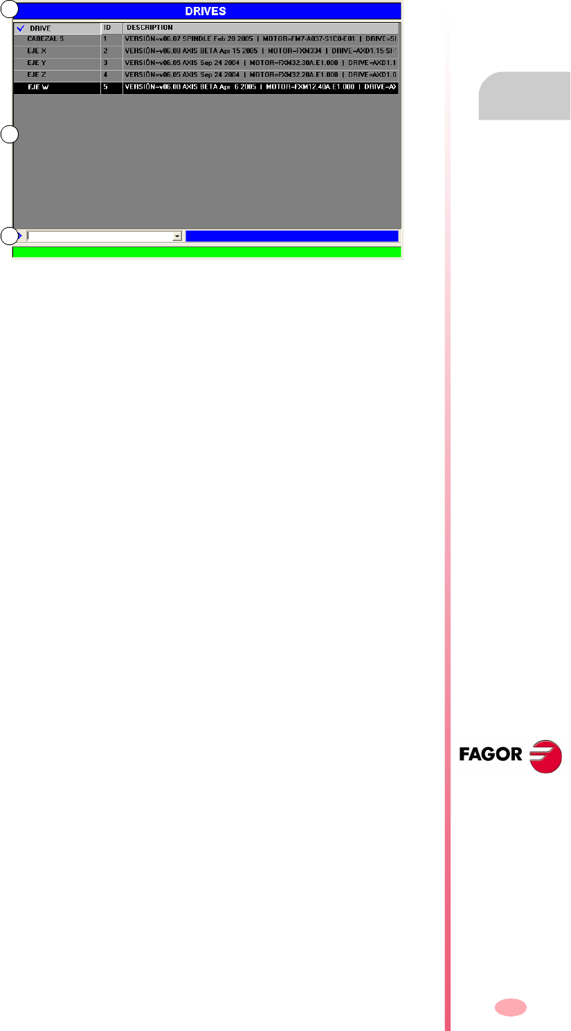
Operating manual
CNC 8070
DDSSETUP
Appearance of the DDSSetup mode
14.
(SOFT V03.0X)
299
14.1.1 Screen description
The DDSSetup screen shows the following information.
A. Title bar that shows the name of the active service.
B. Main window.
C. Command bar.
A
B
C

Operating manual
CNC 8070
14.
DDSSETUP
Appearance of the DDSSetup mode
(SOFT V03.0X)
300
14.1.2 Vertical softkey menu (icons)
List of drives.
Shows the list of Sercos drives connected to the CNC. It shows a short description
of each drive.
Drive accessing level change.
Change the access level for drive parameters and variables. This softkey shows a
window that requests the password to quit the basic level and access a new level.
"Parameters and variables" service.
Shows the list of parameters and variables of the drive. You may choose whether to
show the list of parameters, the list of variables or both.
"Error management" service.
It shows the list of errors detected by the drive. The errors are shown in the order they
come up.
It is also possible to disable some errors.
"Monitoring" service.
It shows a list of variables that are selected by the user.
"Information" service.
This service monitors the status of the operation being carried out at the drive and
the status of the digital inputs and outputs of the drive.
Command simulator.
This option may be used to configure and start up the internal command generator
of the drive.
Select the command bar.
It directly selects the command bar of the DDSSetup. From the command bar, it is
possible to execute different commands of the drive, check variables and modify their
value is they may be written.
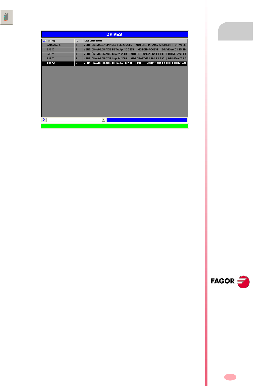
Operating manual
CNC 8070
DDSSETUP
List of drives
14.
(SOFT V03.0X)
301
14.2 List of drives
This service shows a list of Sercos drives connected to the CNC. For each drive, it
shows the name of the axis associated with it, its identifier and a short description
for it, such as software version, motor ID and the ID of the drive itself.
The command bar is located at the bottom of the window. See "14.3 Command bar"
on page 302.
This screen is the one shown by default when accessing the DDSSetup. It can also
be accessed from any other service using the relevant softkey.
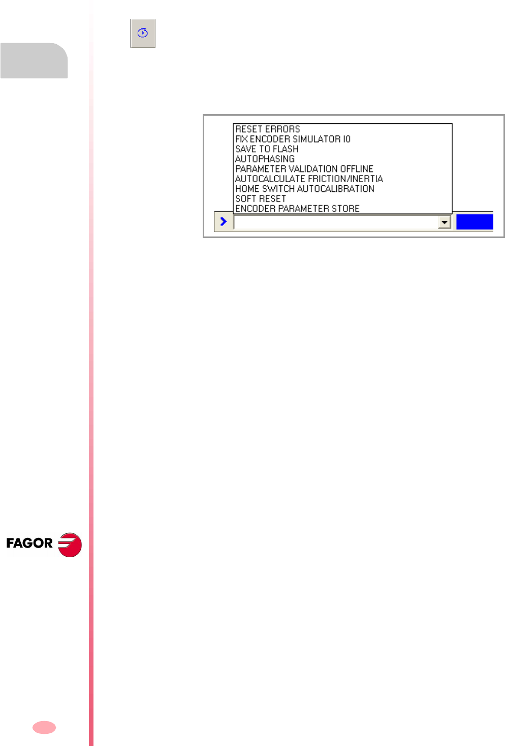
Operating manual
CNC 8070
14.
DDSSETUP
Command bar
(SOFT V03.0X)
302
14.3 Command bar
The command bar is available in various services of the DDSSetup mode. From the
command bar, it is possible to execute different commands of the drive, check
variables and modify their value is they may be written.
Executing commands of the drive
The drop list offers the following commands. To execute one of them, select it from
the list and press [ENTER].
•Resetting errors.
•Setting the encoder simulator reference mark (I0).
•Transferring parameters from RAM to Flash.
•Autophasing.
•Validating.
•Calculating friction and inertia.
•Auto-calibration of the HomeSwitch .
•Soft Reset.
•Saving parameters at the encoder.
Consulting and modifying drive variables
Read-only variables may be consulted (those with the "R" indicator on the attributes
column). Read-write variables may be consulted and/or edited (those with the "RW"
indicator on the attributes column). See "14.5 –Parameters and variables–
service." on page 305.
If a variable has been written, pressing [ENTER] reads its value. If a value is assigned
to a variable, when pressing [ENTER], it assumes the new value.
The command bar may be selected with the window changing key, same as the rest
of the screen elements or using its associated softkey.

Operating manual
CNC 8070
DDSSETUP
Command bar
14.
(SOFT V03.0X)
303
Variables may be identified using their mnemonic or their Sercos identifier. Refer to
the drive's manual to know the list of available variables.
If not indicated otherwise, it accesses the variables of the drive selected in the service.
To access those of a particular drive, select it in the service or add a suffix with the
axis name to the mnemonic (or Sercos ID).
PV210 Consulting the PV210 variable.
S36 Consulting the variable SV1 (Sercos ID = 36).
RV9 = 23 It assigns the value of 23 to the variable RV9.
S36 = 100 It assigns the value of 100 to variable S36 (Sercos ID = 36).
PV210.Y It consults the variable PV210 of the Y axis drive.
S36.S Consulting variable (Sercos ID = 16) of the spindle drive.
Operating manual
CNC 8070
14.
DDSSETUP
Changing the drives accessing level
(SOFT V03.0X)
304
14.4 Changing the drives accessing level
The parameters, variables and commands of the drive are organized by access
levels. To access each parameter, the drive must be configured at the access level
required by that parameter. A password is needed to access each level.
The available access levels are the following:
•Basic level (USER)
It is the default level, it is accessed when entering the DDSSetup mode. It requires
no password.
The user level gives access to a group of parameters that slightly changes the
operation of the drive.
•Intermediate level (OEM)
This level gives access to a large group of parameters that depend on the motor
connected, they set how the electronics of the drive is adapted to that motor.
•Maximum level (FAGOR)
This level gives full access to all the variables, parameters and commands of the
system.
This softkey is used to change the access level for drive parameters. Pressing this
softkey shows a window that requests the password to quit the basic level and access
a new level.
The Fagor level gives access to a group of parameters depending on the
drive's electronics and they factory set.
Only technicians from Fagor Automation are granted a FAGOR access level.
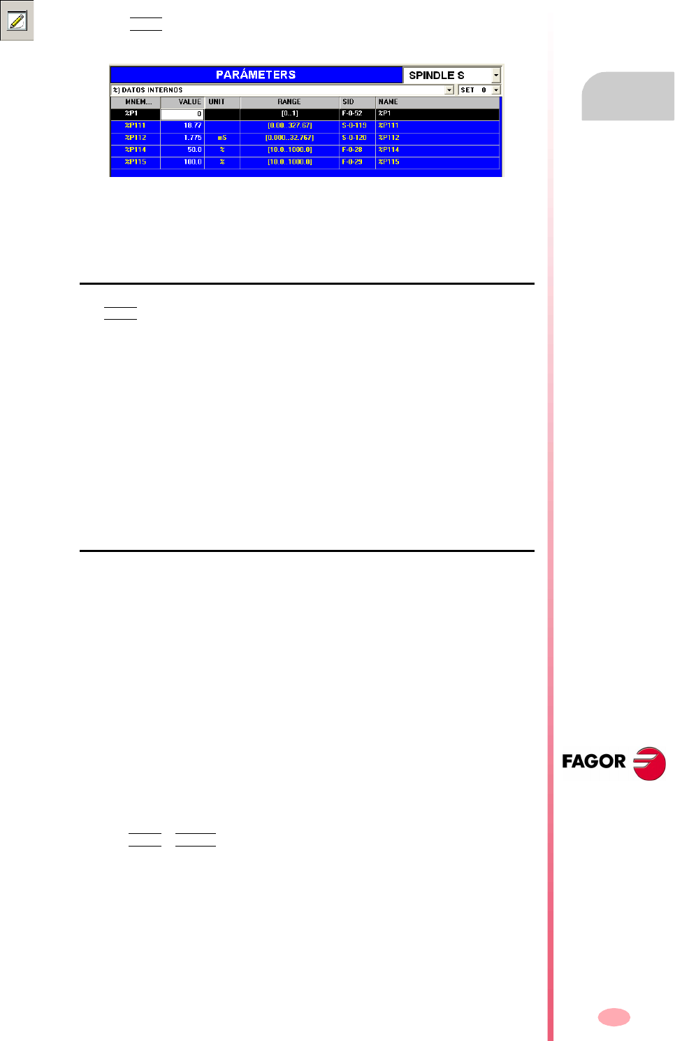
Operating manual
CNC 8070
DDSSETUP
–Parameters and variables– service.
14.
(SOFT V03.0X)
305
14.5 –Parameters and variables– service.
The command bar is located at the bottom of the window. See "14.3 Command bar"
on page 302.
Selection of the elements to be displayed
The VIEW softkey of the horizontal menu may be used to choose displaying either
the parameters and variables, only the parameters or only the variables.
From the top of the window, it is possible to select:
•The drive whose parameters and/or variables are to be consulted.
•The group of parameters and/or variables to work with. Once selected, the list will
show the elements of the selected group.
•The set of parameters to be consulted. Those parameters and/or variables that
have sets will display the values of that set. Also, its identifier will show the selected
set (e.g. for set 4 of the variable SP2, it will show SP2.4)
Parameters with a set will not be affected by the change.
List of variables and parameters
The list of variables and parameters offers the following information.
•Mnemonic of the variable or of the parameter.
•Current value at the drive.
•Units being used.
•Valid range of values. If it is a string of characters, it will show the maximum length
permitted.
•Sercos identifier.
•Name of the variable or of the parameter.
Editing the values
The values, of parameters or variables with write permission are edited in the Value
field. If the new value is accepted, the list shows the change.
The changes are saved in the drive's RAM memory. To save the change permanently,
use the "DATA + FLASH" option of the horizontal menu.
This service shows the list of parameters and/or variables of the drive. It is selected
with the VIEW softkey of the horizontal menu.
Operating manual
CNC 8070
14.
DDSSETUP
–Parameters and variables– service.
(SOFT V03.0X)
306
How to make a backup copy of the data
The DATA softkey of the horizontal menu offers a series of options to make a backup
copy of the values.
•The SAVE softkey saves the values of the parameters and variables into a file.
•The LOAD softkey restores the values of the parameters and variables from a
previously saved file.
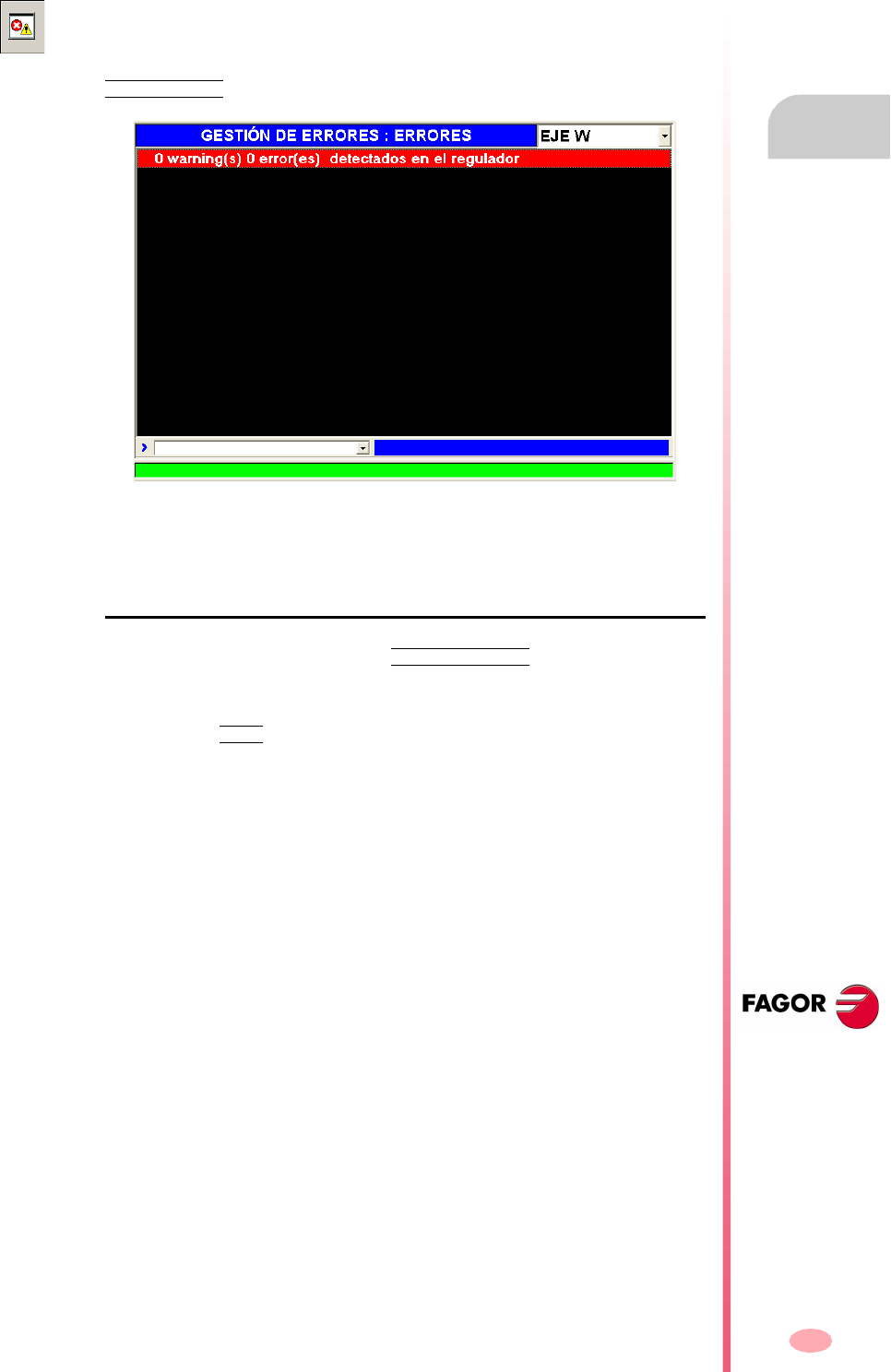
Operating manual
CNC 8070
DDSSETUP
–Error management– service.
14.
(SOFT V03.0X)
307
14.6 –Error management– service.
The command bar is located at the bottom of the window. See "14.3 Command bar"
on page 302.
Disabling the errors
To disable an error of the drive, use the ERROR LISTING softkey of the horizontal
menu. This softkey shows the whole list of possible errors. To disable the desired
ones, checkmark the box on the left.
Then, press the SEND softkey to send the list to the drive. To make the error disabling
effective, execute the command DC1 (reset errors) from the command bar.
Disabling the errors requires an OEM or FAGOR access level. See "14.4 Changing
the drives accessing level" on page 304. Even then, only resettable errors may be
disabled, even if the list also shows the non-resettable errors.
This service shows the list of errors detected by the drive. The errors are shown in
the order they come up.
Once the cause of the error has been corrected, the errors may be reset with the
ERROR RESET softkey of the horizontal menu.
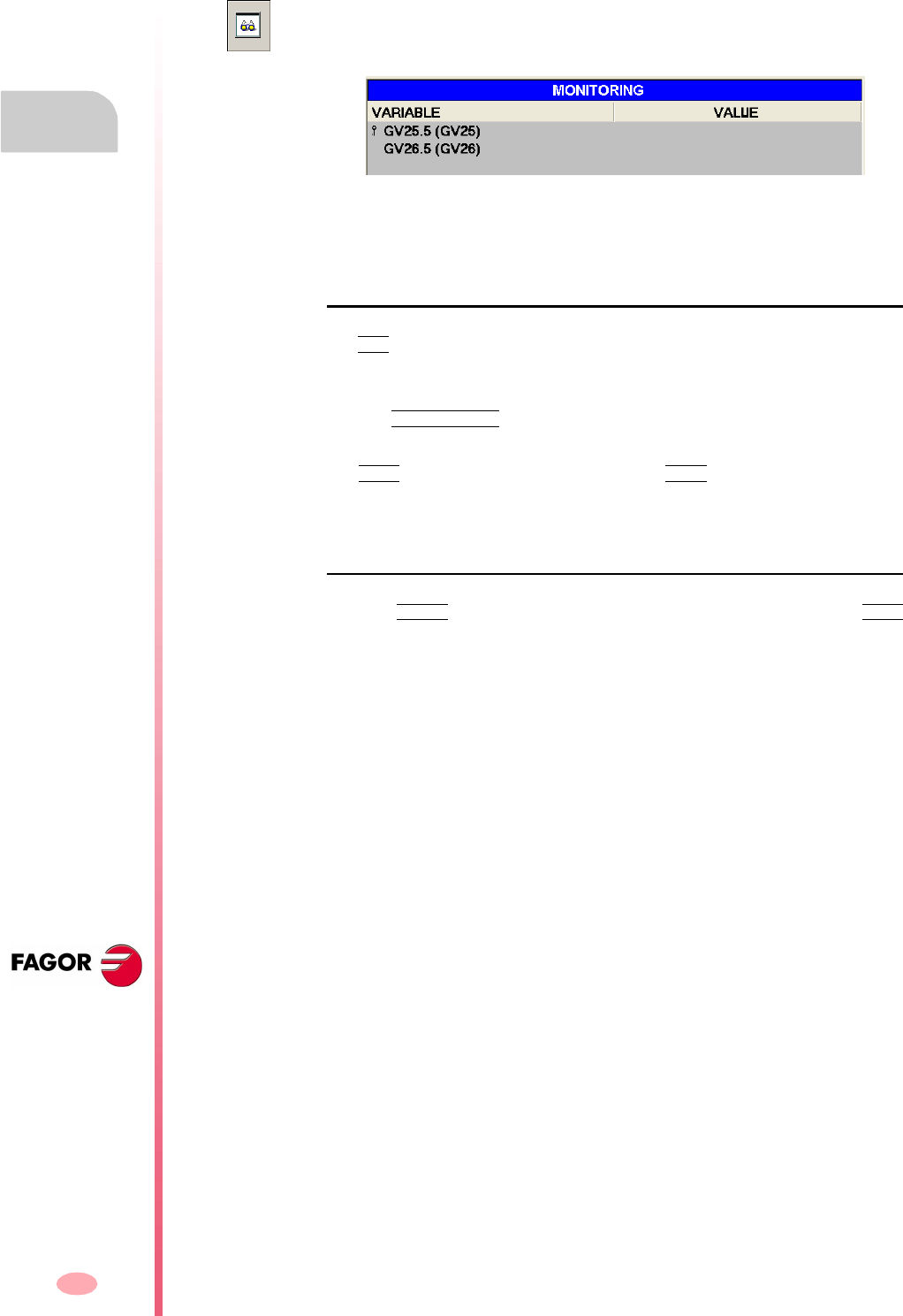
Operating manual
CNC 8070
14.
DDSSETUP
–Monitoring– service
(SOFT V03.0X)
308
14.7 –Monitoring– service
The command bar is located at the bottom of the window. See "14.3 Command bar"
on page 302.
List of variables or parameters
The ADD softkey shows a window where one can select the variables or parameters
to be monitored and they will be shown on the screen. Variables and parameters of
any drive may be selected.
Use the INITIALIZE softkey to clear the whole list. To delete a variable or
parameter from the list, select it and press the [DEL] key.
The SAVE softkey saves the list into a file and theLOAD softkey restores the list from
a file.
Monitoring the status of variables or parameters
Press the START softkey of the horizontal menu to start monitoring. Press the STOP
softkey to stop monitoring.
This service monitors the value of the parameters and variables of the drive. The user
selects the variables and parameters to be monitored.
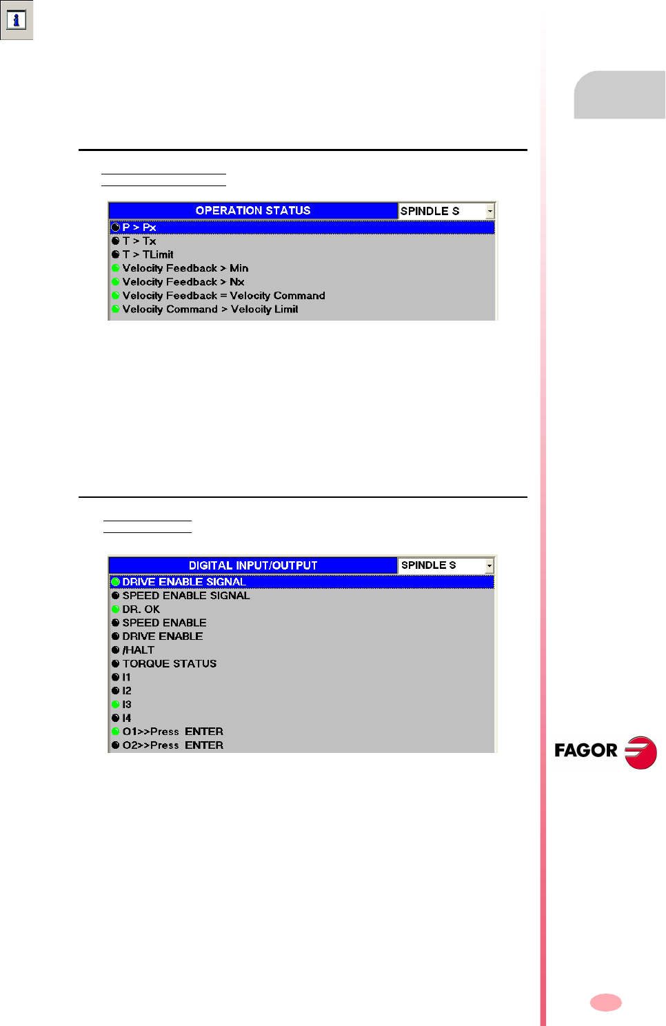
Operating manual
CNC 8070
DDSSETUP
–Information– service
14.
(SOFT V03.0X)
309
14.8 –Information– service
The command bar is located at the bottom of the window. See "14.3 Command bar"
on page 302.
Monitoring the status of the operations of the drive
The OPERATION STATUSsoftkey of the horizontal menu gives access to this option.
This screen monitors the status of the operation being carried out at the drive. The
drive whose operations are to be monitored is selected at the top of the window.
There is a led for each operation and it shows the status of the operation at the drive.
Green led Operation active.
Black led Operation inactive.
Monitoring the status of the operations of the drive
The DIGITAL I/Osoftkey of the horizontal menu gives access to this option.
This screen monitors the status of the digital inputs and outputs of the drive. The drive
whose digital I/O's are to be monitored is selected at the top of the window.
There is a led for each digital input and output of the drive and it shows its status.
Green led Input or output active.
Black led Input or output inactive.
This service monitors two types of information. It shows the status of the operation
being carried out at the drive, on the other hand it shows the status of the digital inputs
and outputs of the drive.

Operating manual
CNC 8070
14.
DDSSETUP
–Information– service
(SOFT V03.0X)
310
Type of inputs and outputs
The inputs and outputs may be grouped as follows.
•Inputs and outputs that cannot be assigned.
These inputs and outputs indicate the status of the drive's control signals.
•Inputs and outputs that may be assigned.
Variables and/or parameters of the drive may be associated with inputs and
outputs (analog and digital).
Those digital outputs that have not been associated with any parameter or
variable may be forced to become active or inactive using the button on the left
of their led.
Speed enable Drive enable Error Reset
LSC Status DR. OK PROG. OK
Master Speed Enable Master Drive Enable Master Halt
Torque Status
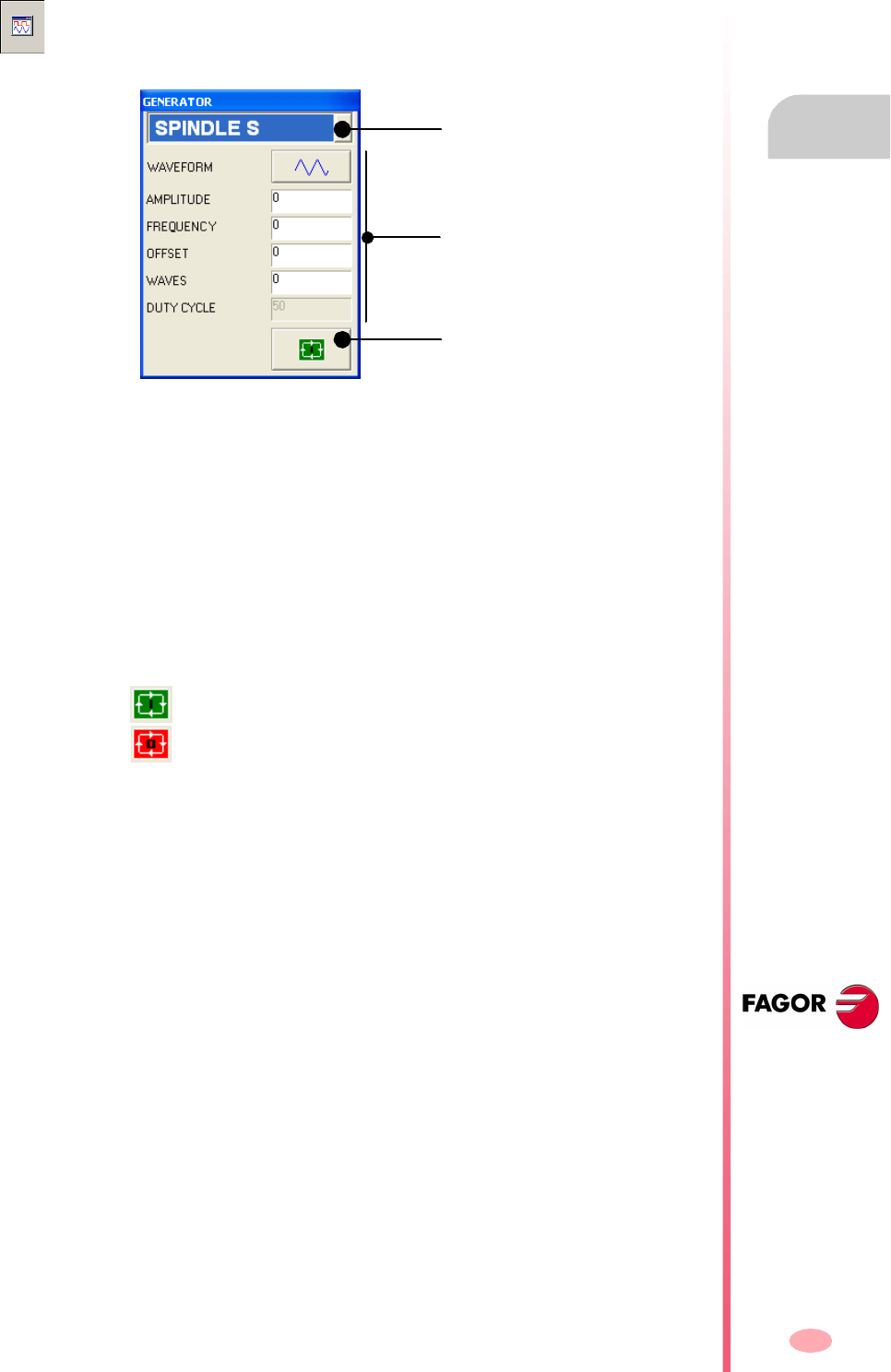
Operating manual
CNC 8070
DDSSETUP
Command generator
14.
(SOFT V03.0X)
311
14.9 Command generator
The fields to be configured at the generator are:
Shape To select the type of signal to be generated with the drive
(sinusoidal or square).
Amplitude Signal amplitude.
Frequency Signal frequency.
Offset Signal Offset.
Waves Number of waves to generate. When set to 0 (zero), the
waves are generated continuously, without interruption.
Duty Cycle Percentage of the wave at 1/0 (only on squarewaves).
The internal command generator is turned on and off using the lower buttons.
This option may be used to configure and start up the internal command generator
of the drive. In the configuration, it is possible to establish the shape of the signal,
its amplitude, period, etc.
It turns the command generator on.
It turns the command generator off.
Selected drive
Turn the command generator
on.
Configuration of the command
generator.

Operating manual
CNC 8070
14.
DDSSETUP
Command generator
(SOFT V03.0X)
312
313
CNC 8070
(SOFT V03.0X)
15
DIAGNOSIS
This operating mode may be used to test the hardware and software of the PC that
the CNC is based upon.
•System information.
•Information about the modules that make up the CNC software.
•Information about the elements connected to the CNC through the CAN bus and
SERCOS.
The diagnosis is a testing and displaying tool; it cannot be used to modify the
displayed values.
Diagnosis mode selection
The diagnosis mode may be accessed either using the user key customized for it or
from the tasks window. The task window may be accessed with key combination
[CTRL]+[A].

Operating manual
CNC 8070
15.
DIAGNOSIS
Appearance of the diagnosis mode
(SOFT V03.0X)
314
15.1 Appearance of the diagnosis mode
When this operating mode is active, it will be indicated at the top right side of the
general status bar.
This operating mode may be displayed with several screens. Each one corresponds
to an element of the CNC configuration.
Standard configuration
The standard configuration of this work mode, described in this manual corresponds
to the one supplied by Fagor. In some cases, the manual shows a sample screen,
instead of that of the CNC in order to make it easier to understand.
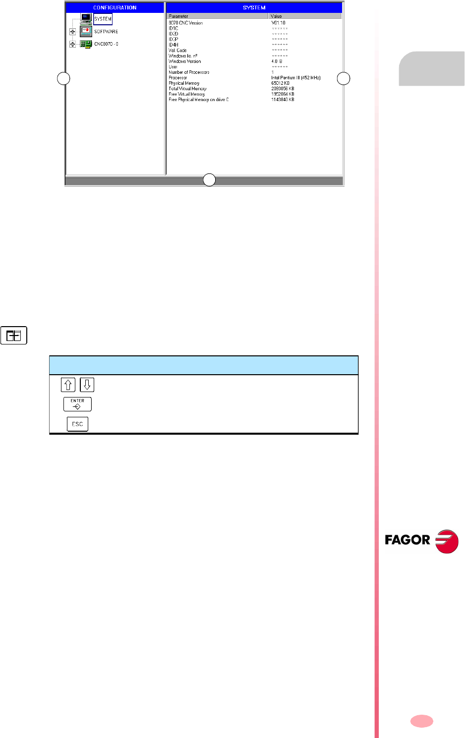
Operating manual
CNC 8070
DIAGNOSIS
Appearance of the diagnosis mode
15.
(SOFT V03.0X)
315
15.1.1 Screen description
The diagnosis screen shows the following information.
A. It shows the hardware and software configuration of the CNC.
System diagnosis: Information on the system elements; CNC version, user name,
microprocessor(s) used, status of the various system memories, etc.
Software diagnosis: Information about the modules that make up the CNC
software and the software options installed.
CNC8070 diagnosis: Information about the elements connected to the CNC
through the Can bus and Sercos (drives, input/output cards, etc.).
B. Diagnosis of the selected element.
C. CNC messages.
A B
C
To switch windows, press the relevant key.
After selecting an element of the configuration
Hide or display the list of resources of an element.
To move the cursor through the elements of the list.
To move the cursor to the beginning or end of the list.
Operating manual
CNC 8070
15.
DIAGNOSIS
Appearance of the diagnosis mode
(SOFT V03.0X)
316
15.1.2 Icon description (vertical softkeys)
The icon menu always shows all the icons related to this work mode.
The icons are activated with their associated softkey (F8 to F12).
List of icons
Update data
It is used to update (refresh) the data of the diagnosis window.
Print table
It prints the information of the configuration out to a printer connected to the CNC or
as a file at the CNC (in *.PRN format).
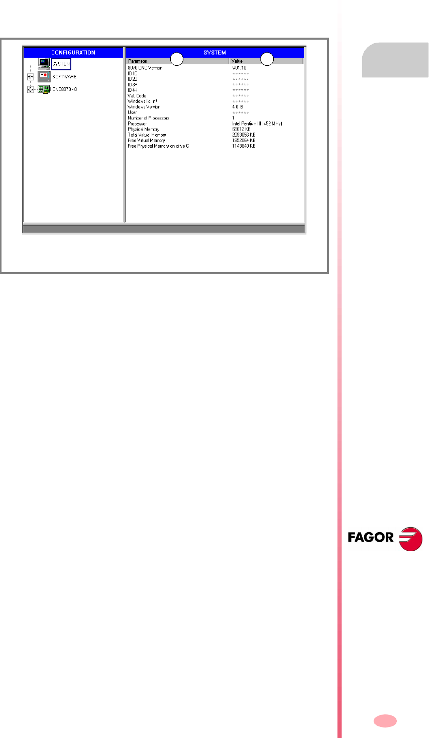
Operating manual
CNC 8070
DIAGNOSIS
Configuration diagnosis
15.
(SOFT V03.0X)
317
15.2 Configuration diagnosis
15.2.1 System diagnosis
When selecting this configuration element, the diagnosis window shows the list of the
system elements and their values.
(A) System elements.
(B) Element values.
A B
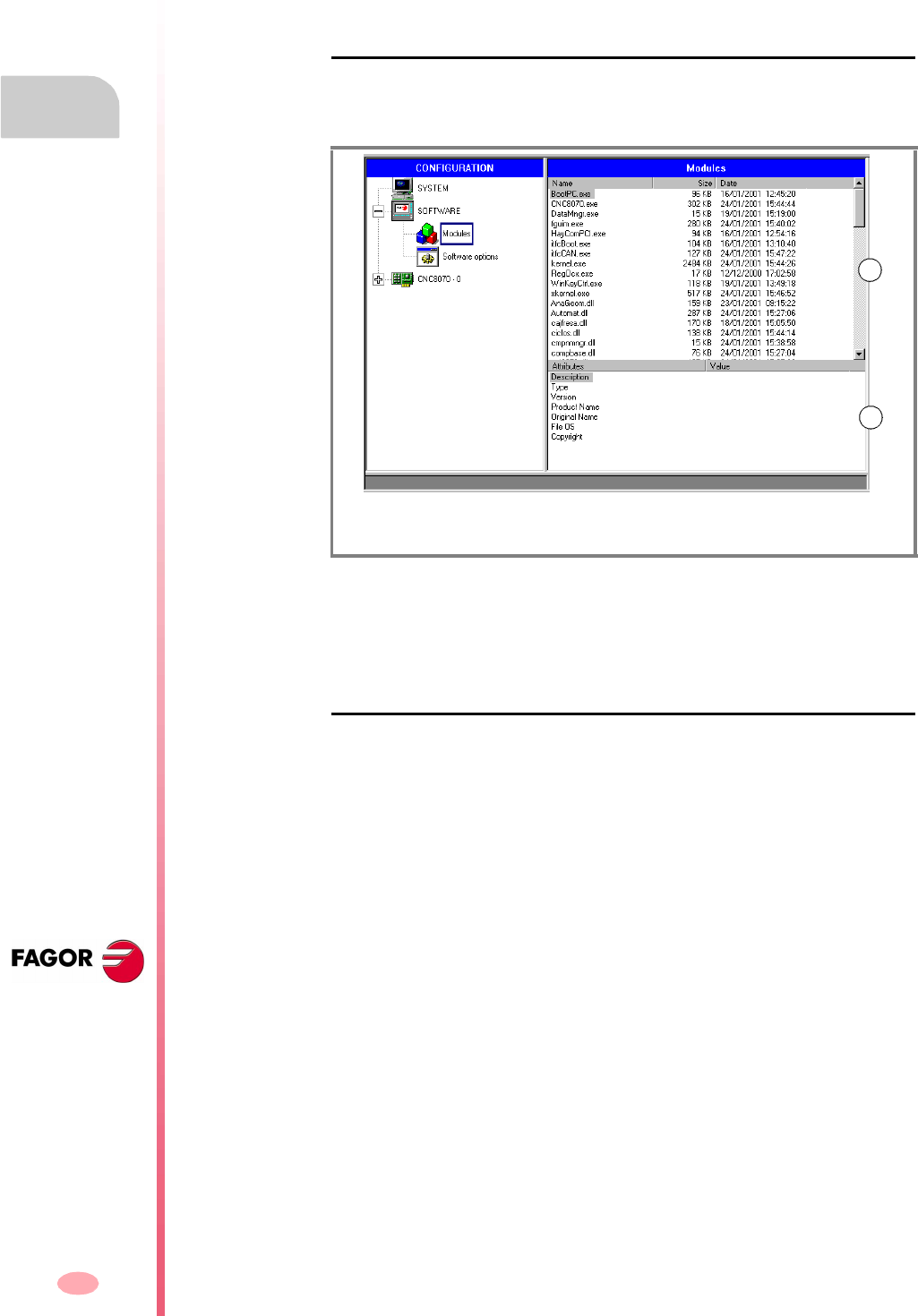
Operating manual
CNC 8070
15.
DIAGNOSIS
Configuration diagnosis
(SOFT V03.0X)
318
15.2.2 Software diagnosis
This option may be used to analyze the modules that make up the CNC software and
the software options installed.
Module information
When selecting this configuration element, the diagnosis window shows the list of the
modules that make up the CNC software.
It shows the size of each module (in bytes) and the date it was created. When
selecting a module from the list, the bottom of the screen shows more detailed
information.
Software options
When selecting this element of the configuration, the diagnosis window shows the
software options currently installed.
It also shows the horizontal softkey VALIDATION CODE for entering the resulting
validation code according to the hardware ID of the unit and the desired options.
(A) Modules listing.
(B) Detailed information of the selected module.
A
B
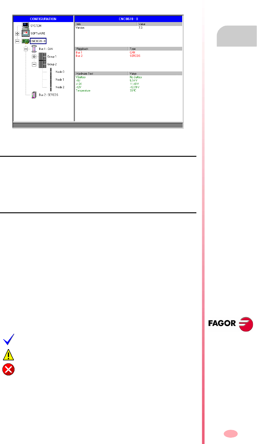
Operating manual
CNC 8070
DIAGNOSIS
Configuration diagnosis
15.
(SOFT V03.0X)
319
15.2.3 Hardware diagnosis. CAN bus and SERCOS
When selecting this element of the configuration, the diagnosis window shows the
software identification of the CNC's communications board (version, boot,
checksum) and the type of buses connected to it. Likewise, it monitors the different
voltage and temperature alarms.
Sercos bus configuration
•Listing of nodes and drive associated with each one of them.
For each drive, it indicates its software version, type of drive and the motor
connected to it.
Can bus configuration
•Resources connected and their status.
•Groups connected and number of nodes that make up each group (detected and
active).
Detailed information of the selected group.
•Group resources and their status.
•Information about the nodes that make up the group.
Detailed information of the selected node.
•Software version, boot and checksum of the code.
•Node status.
•Resources of each module.
The symbol next to the node indicates its status and its possible association.
Active.
Active, but in error.
Inactive.

Operating manual
CNC 8070
15.
DIAGNOSIS
Sercos diagnosis
(SOFT V03.0X)
320
15.3 Sercos diagnosis
General information about the bus
General purpose, it shows the following information about the Sercos bus.
General information about the bus
It shows the following information for each drive.
General information
Error information
Information on the last operation carried out by the service channel
Version SERCON chip version.
Loop time Time between two synchronization messages (MST). It is the same as general
parameter LOOPTIME.
T2 Time from the MST until the CNC starts sending the telegram with the position
commands (MDT).
T3 Time from the MST until the drives have the position commands.
T4 Time from the MST when the drives read the feedback values.
TL Time from the MST until the RT IT takes place at the CNC.
Distortion errors Distortion error counter at the CNC.
Ring errors Sercos ring error counter.
Phase Current Sercos phase.
Phase status Phase status (0 = OK).
Logic ID and name Name and driveID (number of the rotary switch) of the Sercos axes.
T1 Time from the MST until the drive starts sending its telegram (AT).
Control word Contents of the drive's control word.
Status word Contents of the drive's status word.
Name Name of the Sercos axis.
"Reset Hard" counter Number of times that the drive has been reset.
Distortion errors Counter of distortion errors detected at the drive.
AT errors Counters of AT reception errors of each drive.
ID Processed Sercos ID.
Element Processed data (Name, Units, min/max Value, Status, Value, Attributes).
Process Operation carried out (Read, Write).
Command status In processes with commands, it indicates its status.
Error code Operation error code (0 = OK).

Operating manual
CNC 8070
DIAGNOSIS
Save the CAN configuration for the start-up test.
15.
(SOFT V03.0X)
321
15.4 Save the CAN configuration for the start-up test.
Saving a CAN configuration to a file serves to check the CAN configuration is correct
when starting the system up. The CAN configuration must only be saved to a file after
having verified that it is correct.
Save the CAN configuration.
When the CAN bus level is selected, it shows the SAVE softkey that may be used to
save the current CAN configuration. The configuration is saved in the file C:\Cnc8070
\mtb \data \canData.tab.
This file contains the number of groups present in the bus, the number of modules,
the number of inputs and outputs, etc.
Verify the CAN configuration during power-up.
To verify the configuration, the information must be previously saved to the file
canData.tab.
During the power-up process, the data saved in the canData.tab file is compared with
the data read during power-up. If when comparing the data, they are not the same,
the corresponding error message is issued.
"The CAN configuration is not the same as the one saved in the file"
Once the error is detected, it will keep coming up even after a reset. There two ways
to correct the error:
•Power up the CNC again with the original CAN configuration; the one saved in
the canData.tab file
•Save the new CAN configuration. The CAN configuration must only be saved to
a file after having verified that it is correct.

Operating manual
CNC 8070
15.
DIAGNOSIS
Generate a report with the system information
(SOFT V03.0X)
322
15.5 Generate a report with the system information
A report with all the information offered by the diagnosis mode may be obtained from
any section of the diagnosis mode. This information may be printed or saved to a file.
This produces a document with all the information about the FAGOR system installed
on a machine such as the software version, status of the remote modules, installed
drives and motors, etc.
When printing to a file, it is possible to select the name and location of the file.
To print the information, use the "Print" icon. When pressing this icon, the CNC will
show a dialog box requesting the print destination for the document (printer or file).
CNC 8070
(SOFT V03.0X)
323
Operating manual
CNC 8070
(SOFT V03.0X)
324
Operating manual
