Fargo Electronics OMNI5121 Omni Key Reader User Manual
Fargo Electronics Inc Omni Key Reader
UserManual.wiki
>
Fargo Electronics
>
OMNI5121 User Manual
User Manual
Navigation menu
Upload a User Manual
Namespaces
Wiki Guide
HTML
PDF
Info
Views
User Manual
Discussion / Help
Navigation


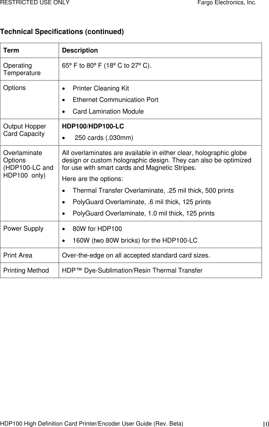
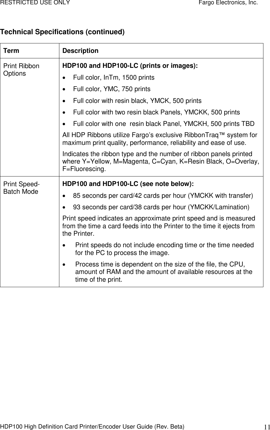
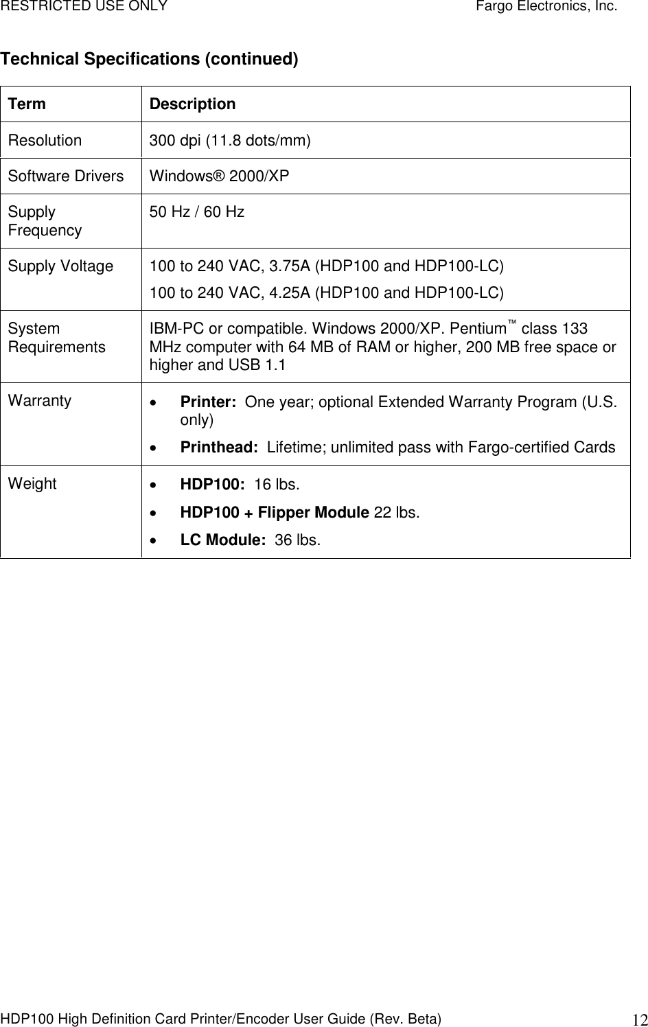
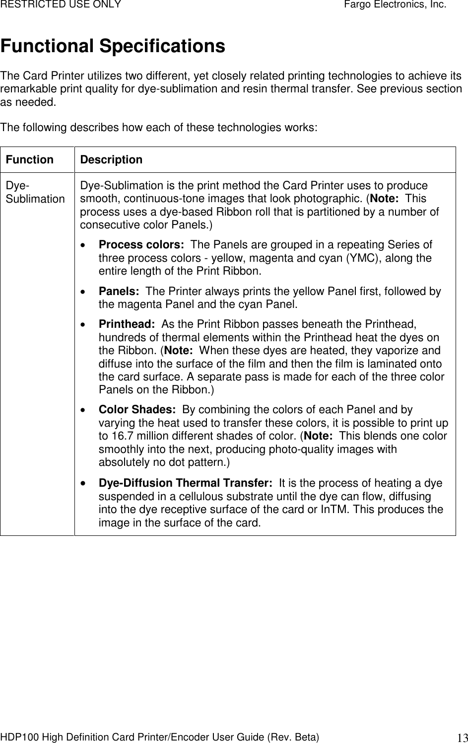
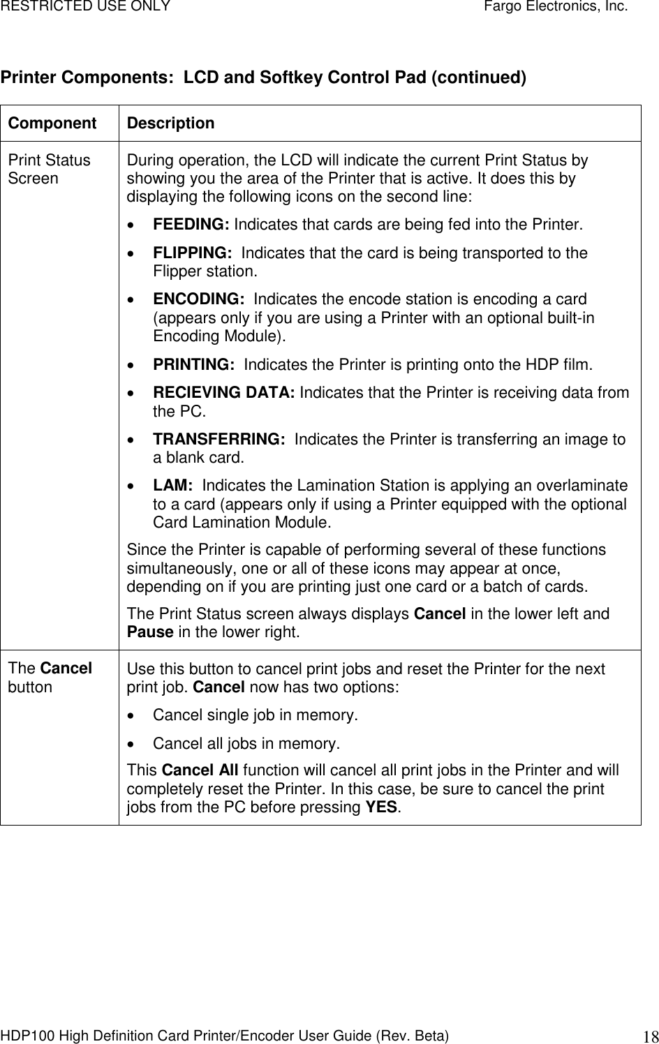
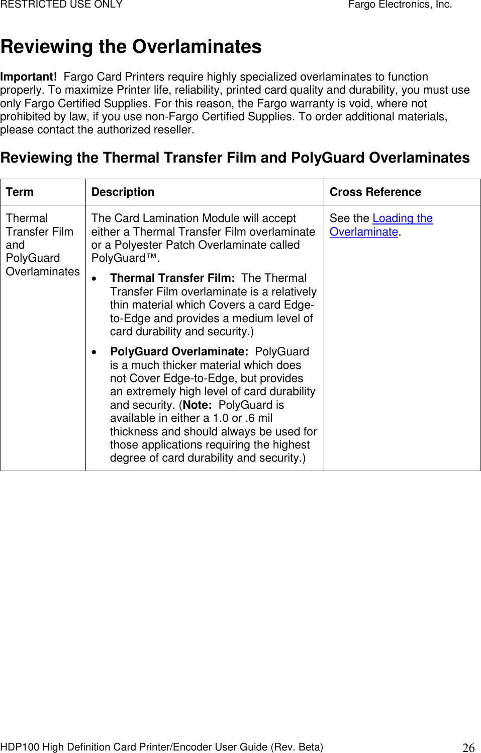
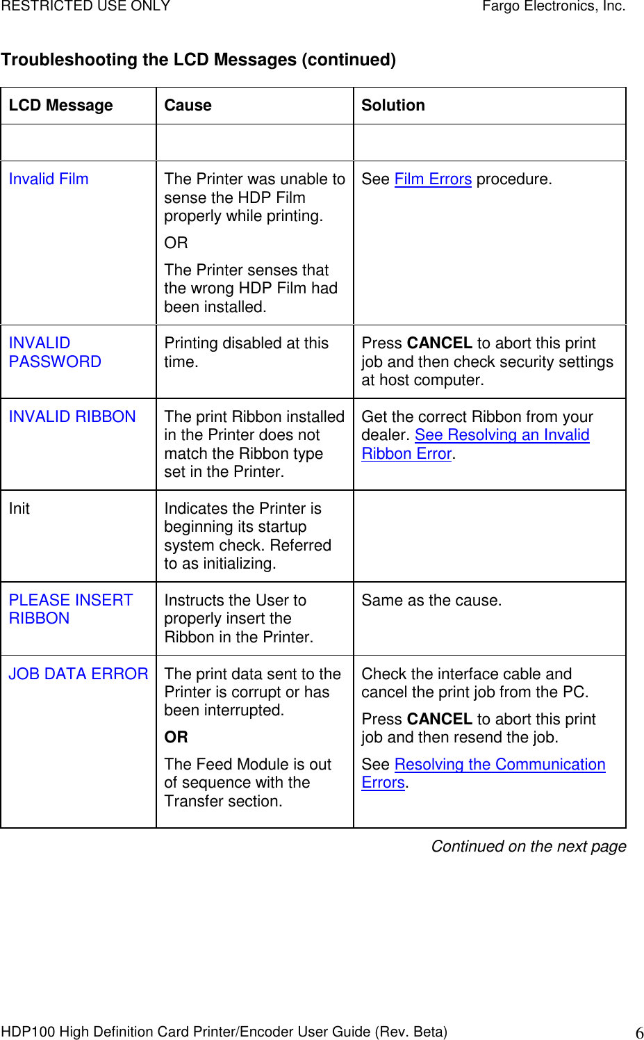
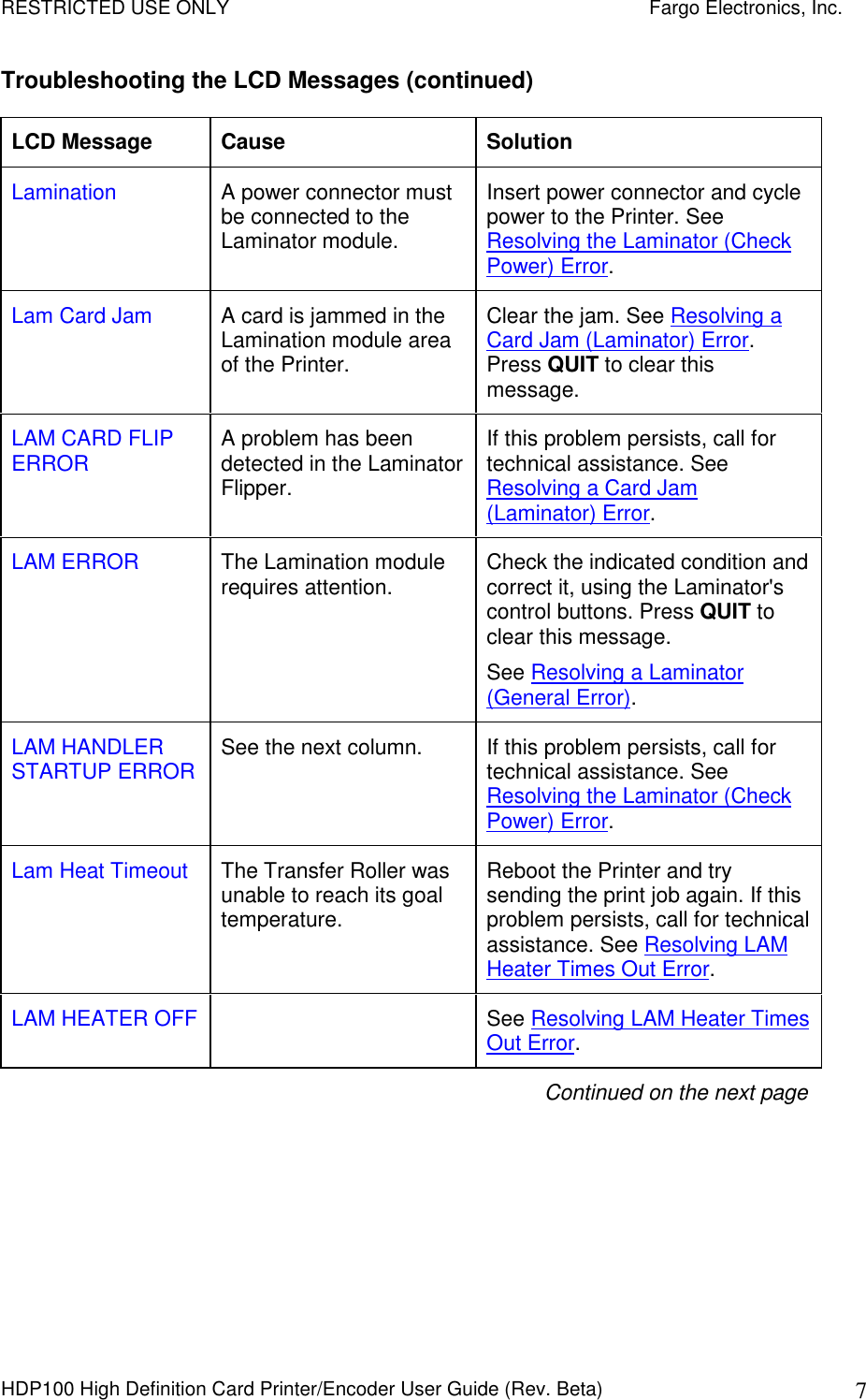
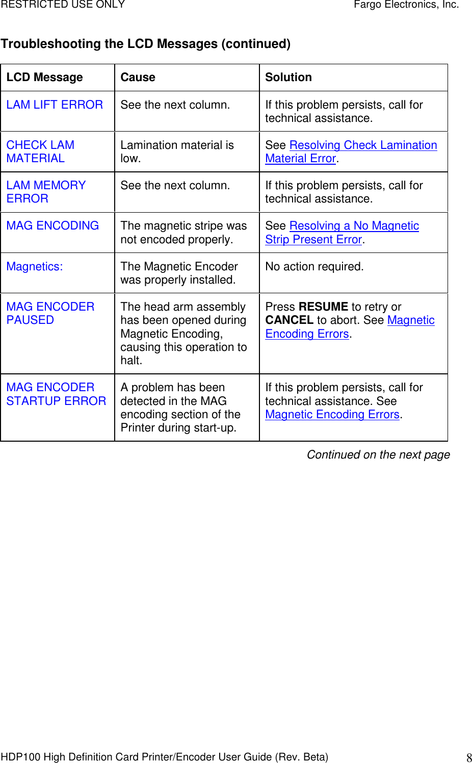
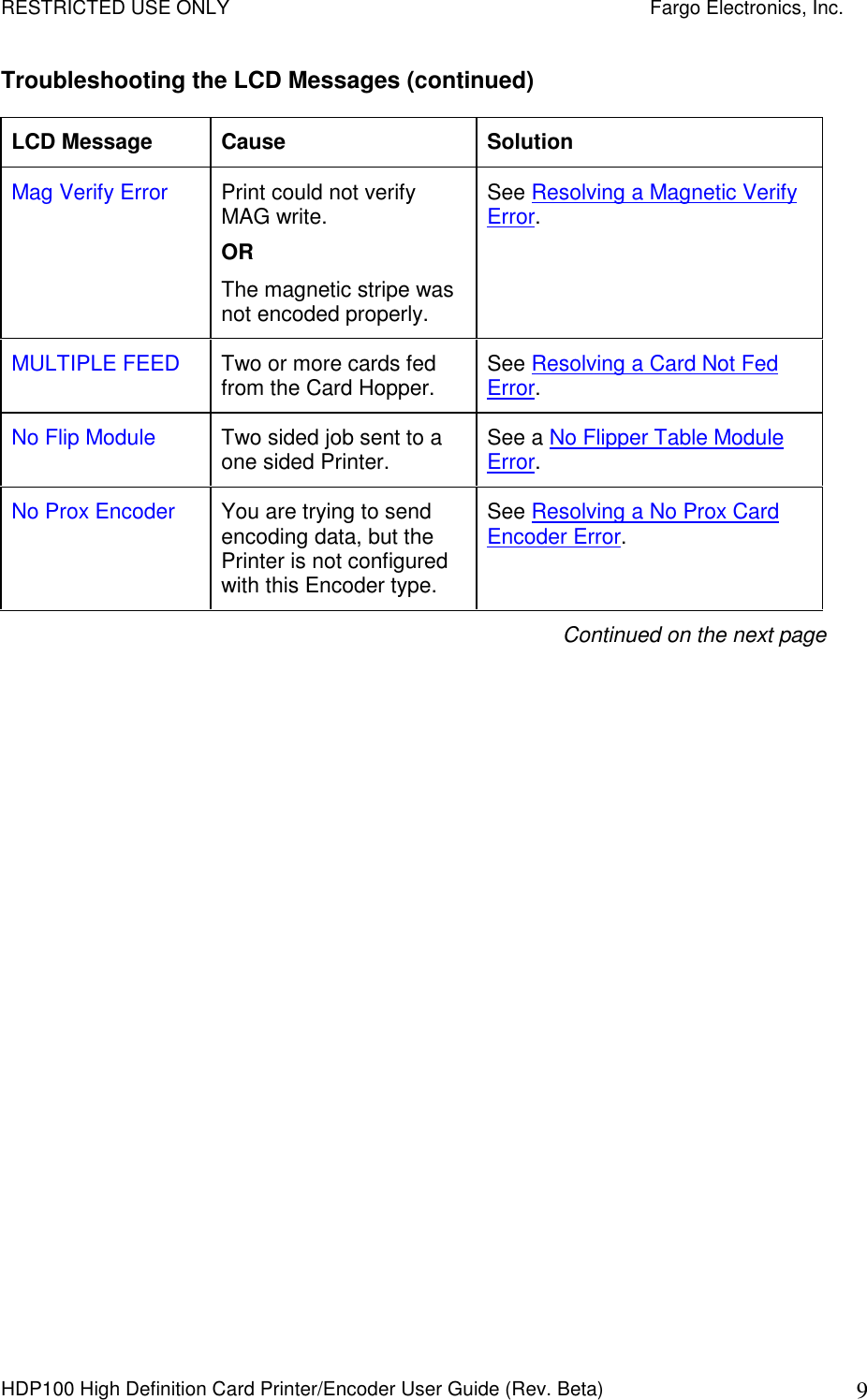
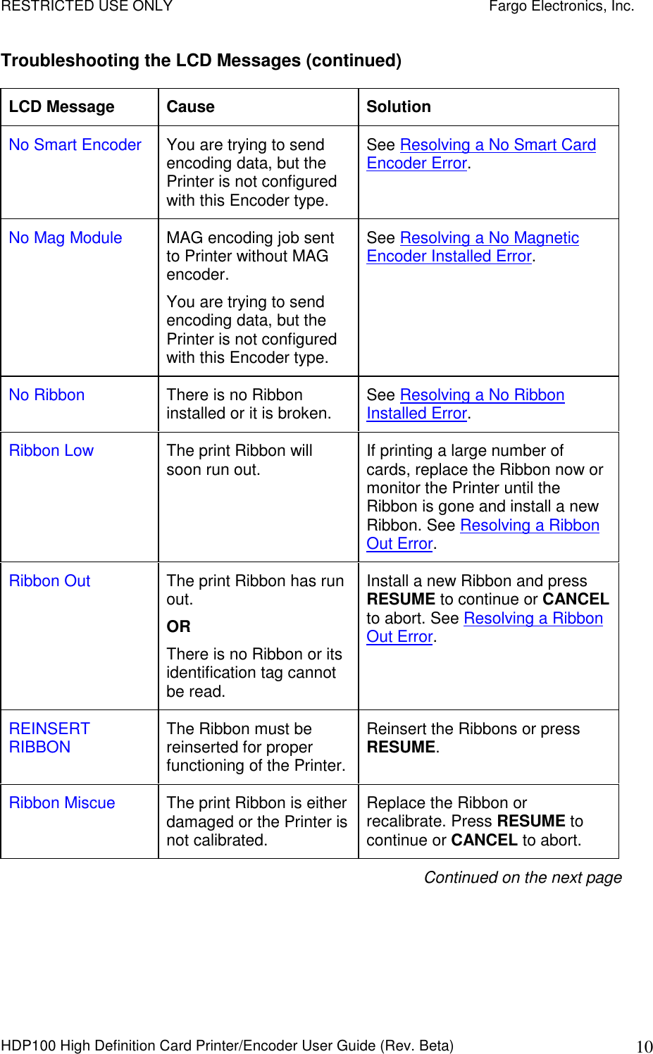
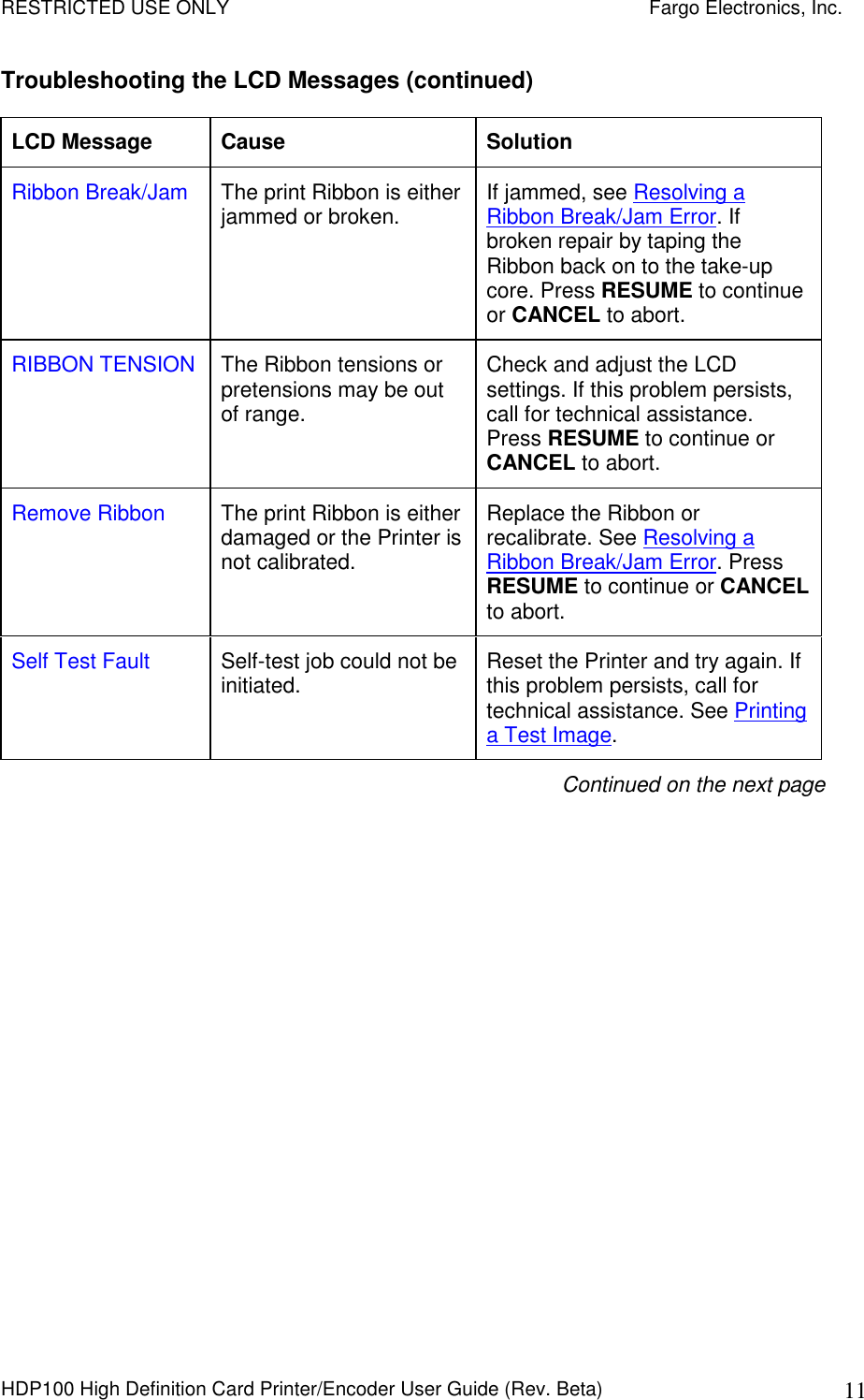
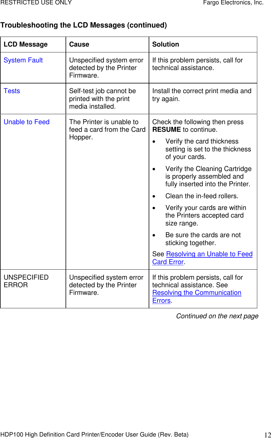
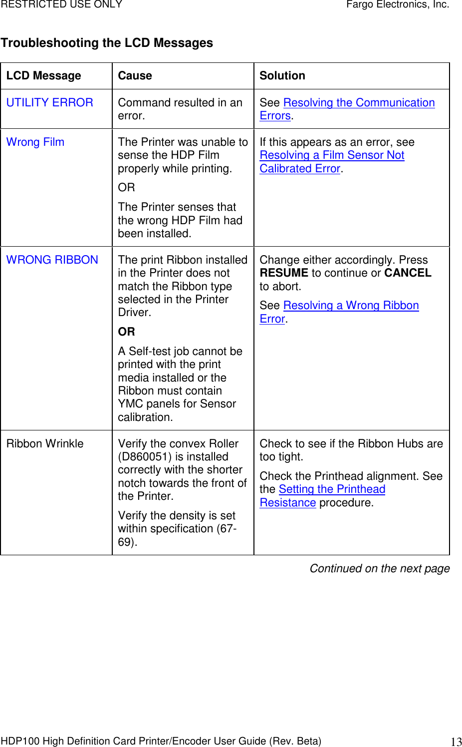
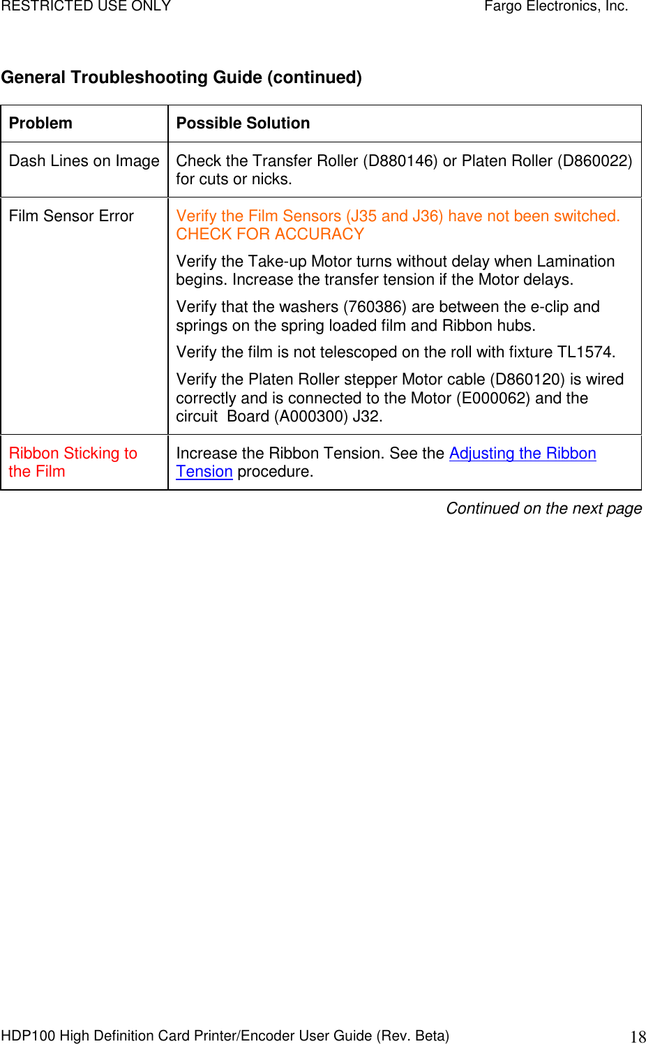
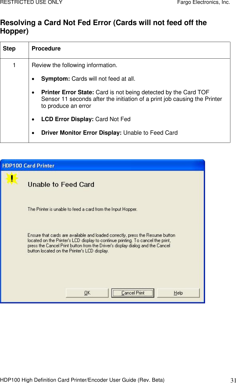
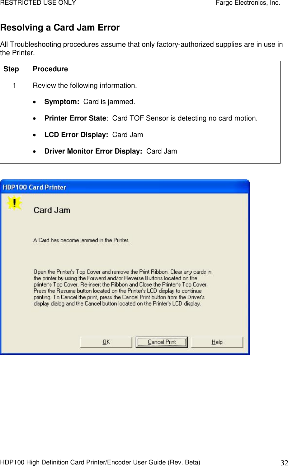
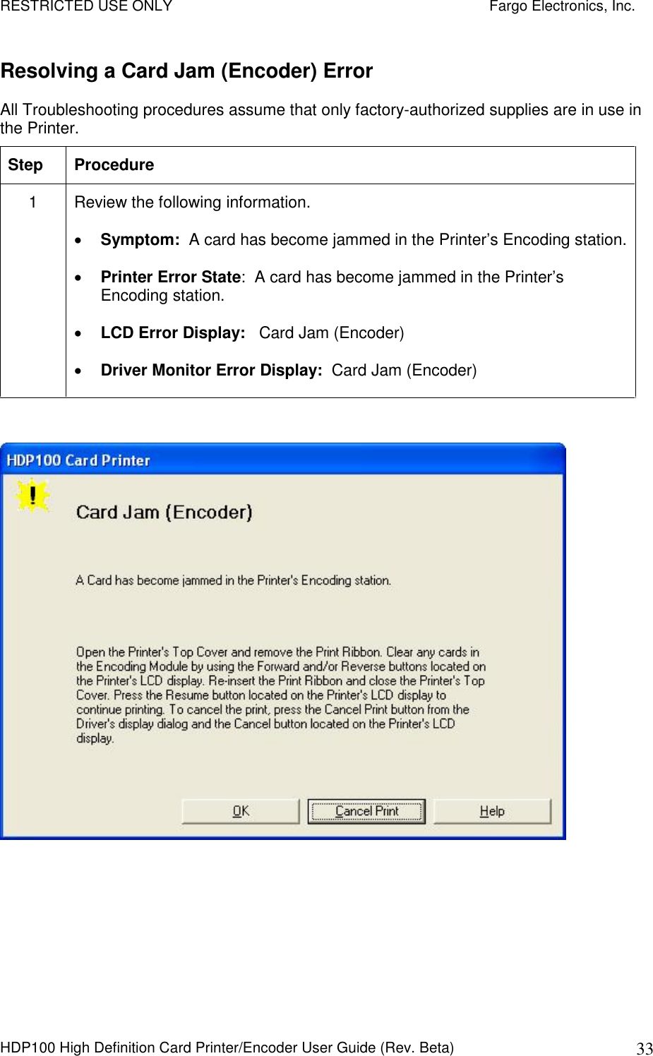
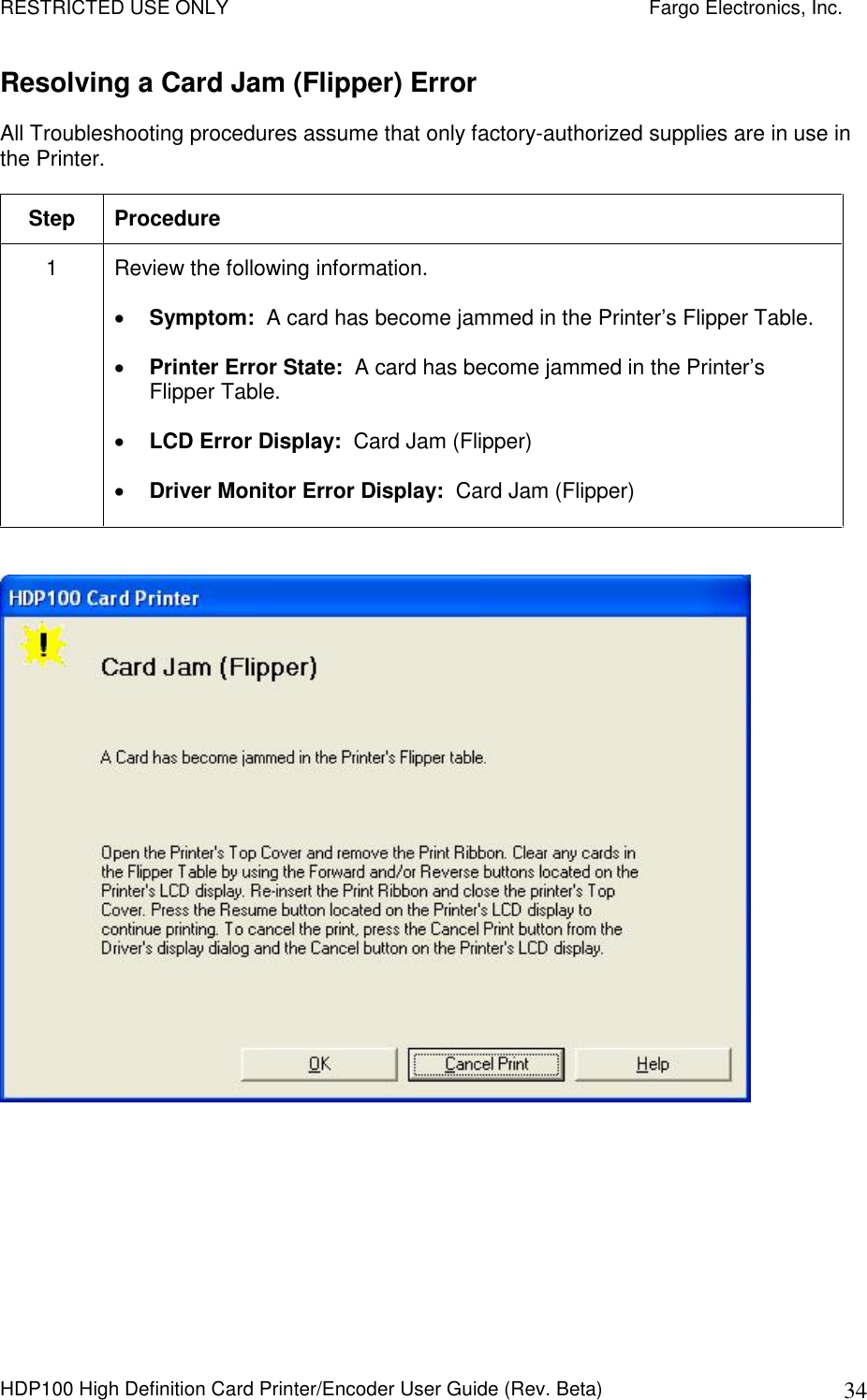
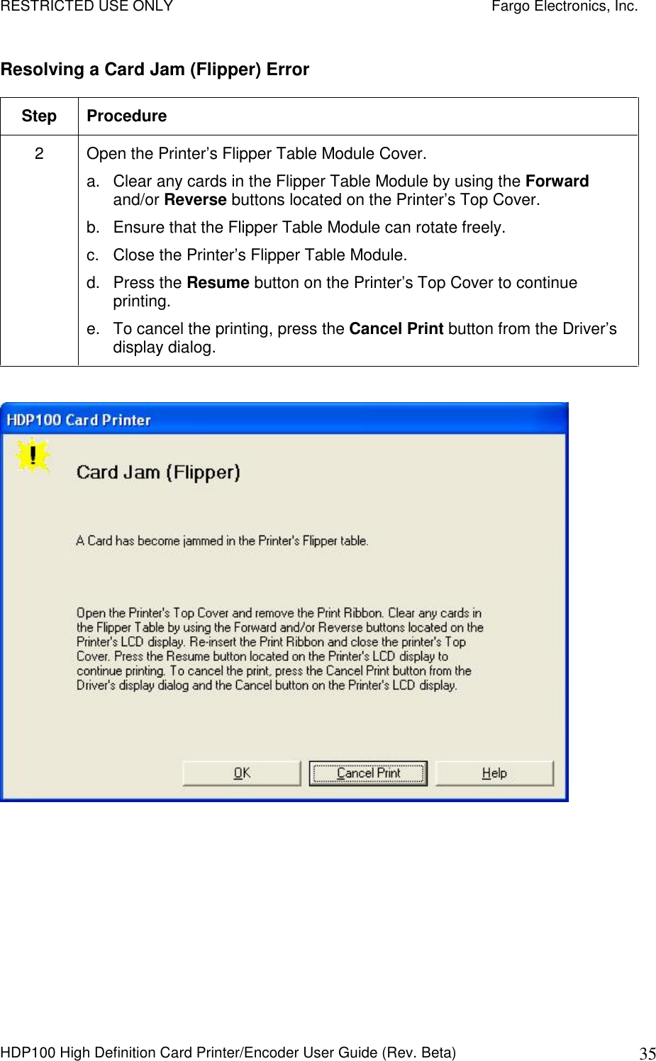
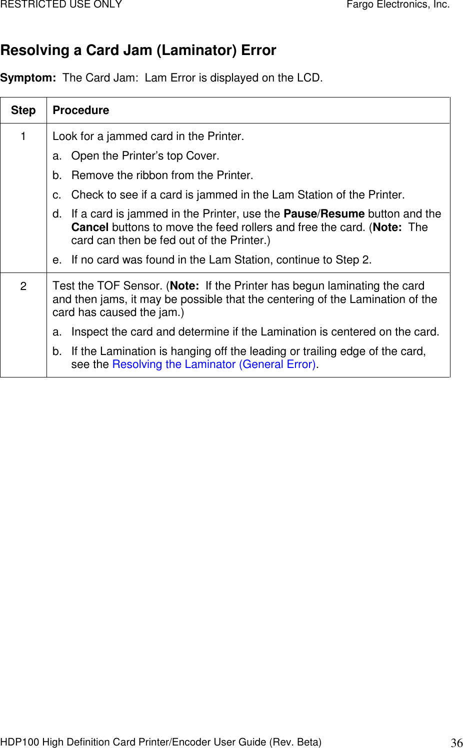
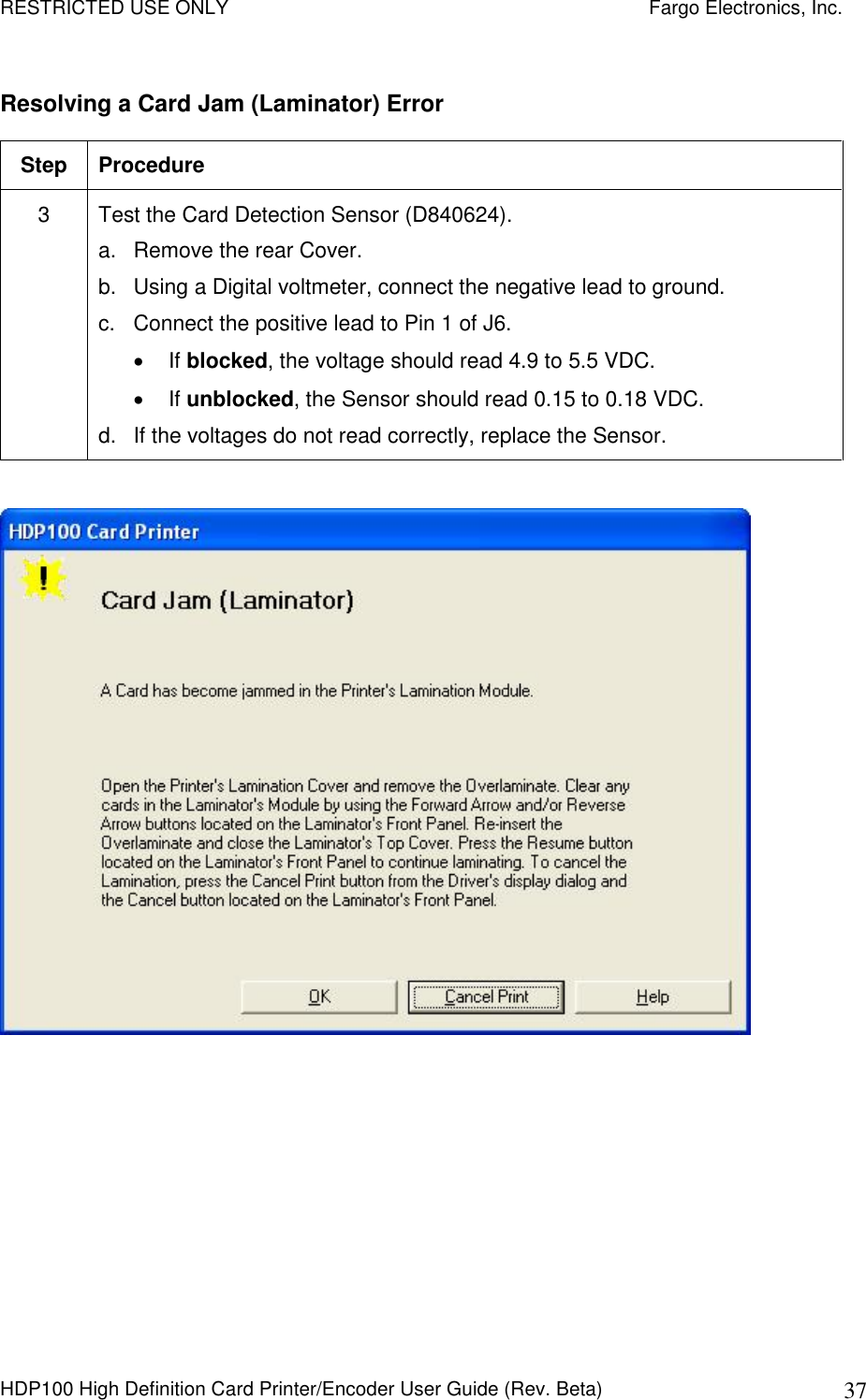
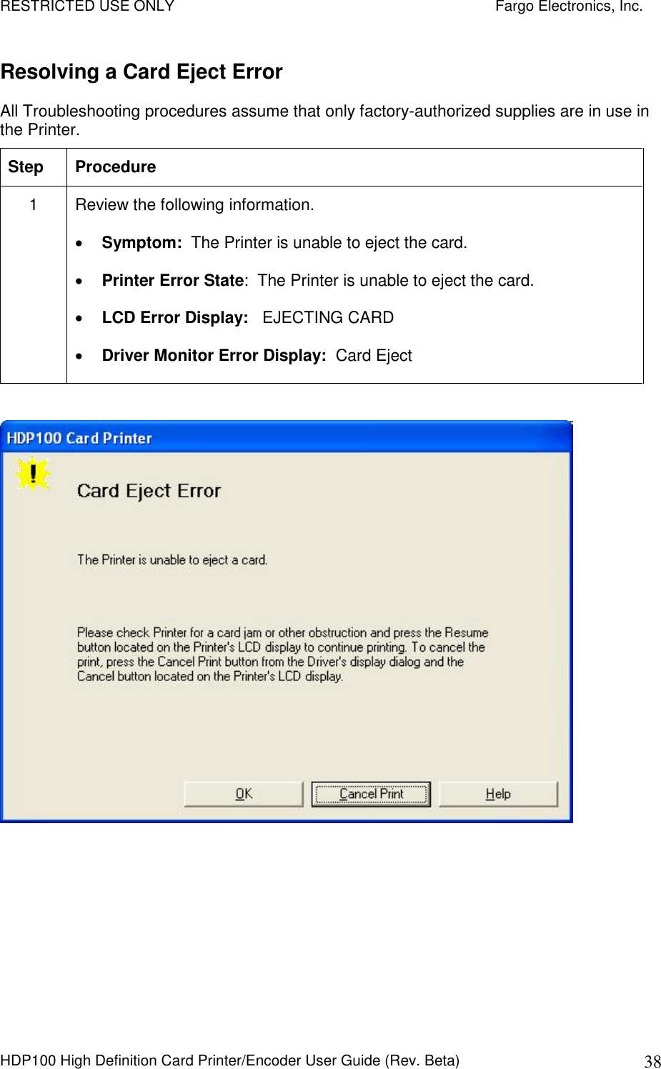
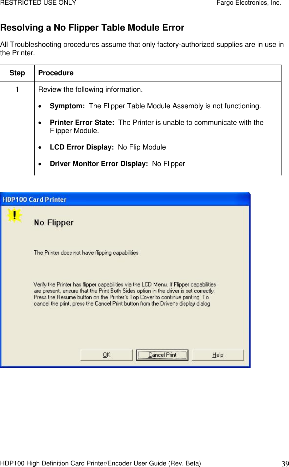
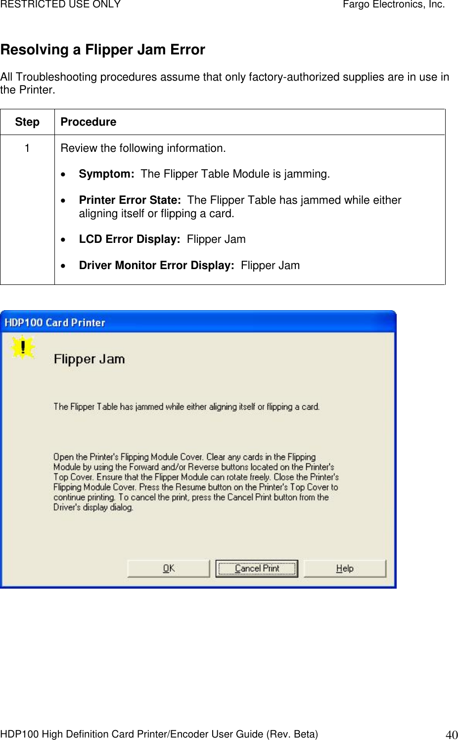
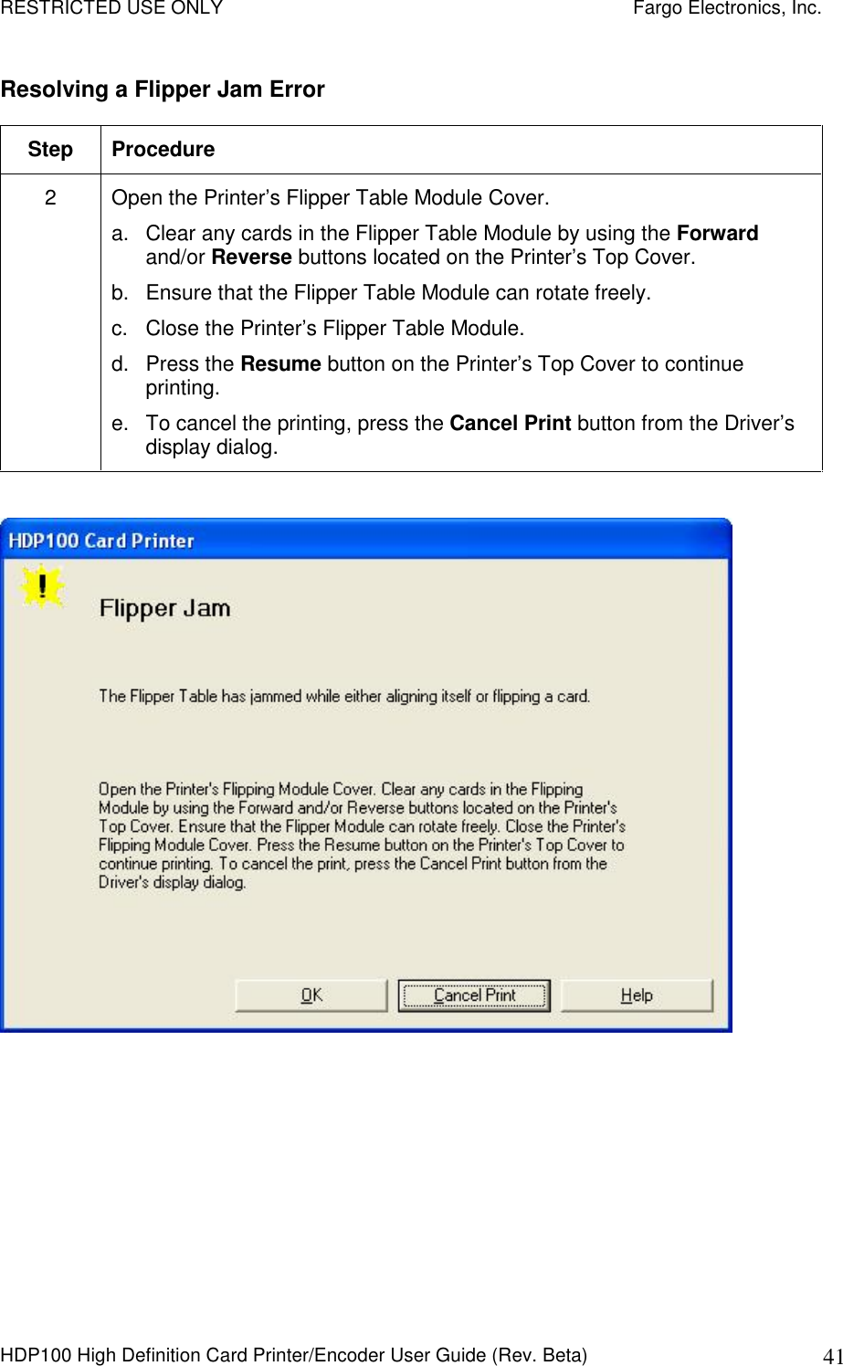
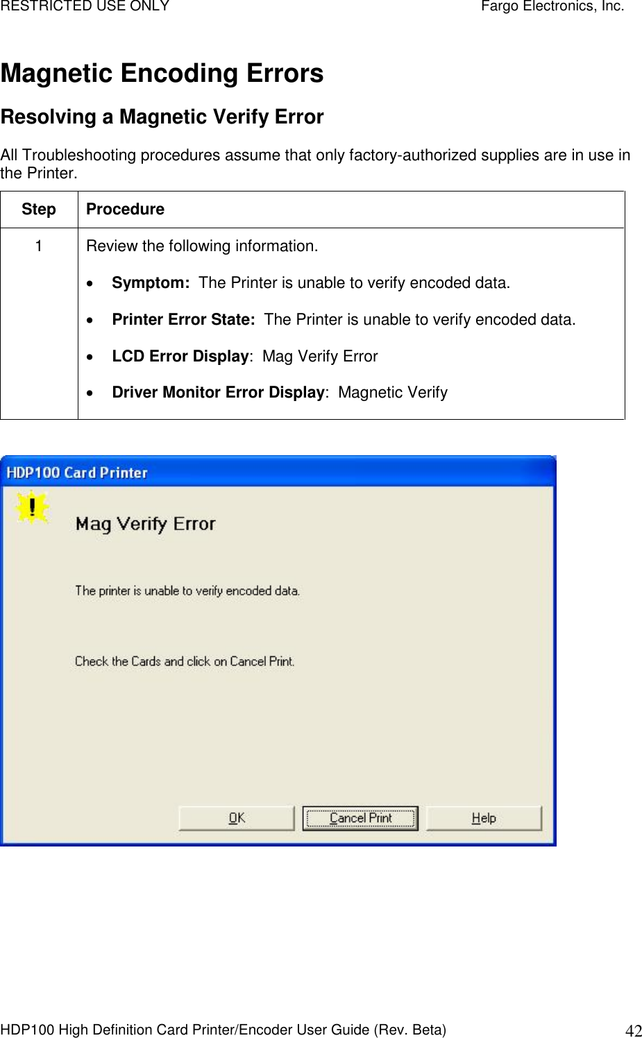
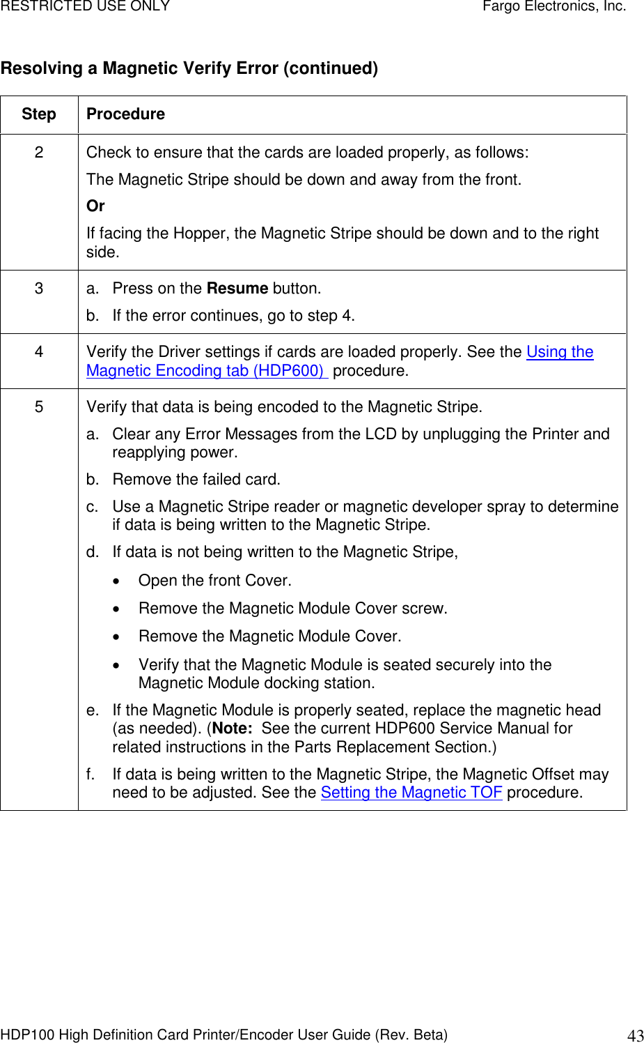
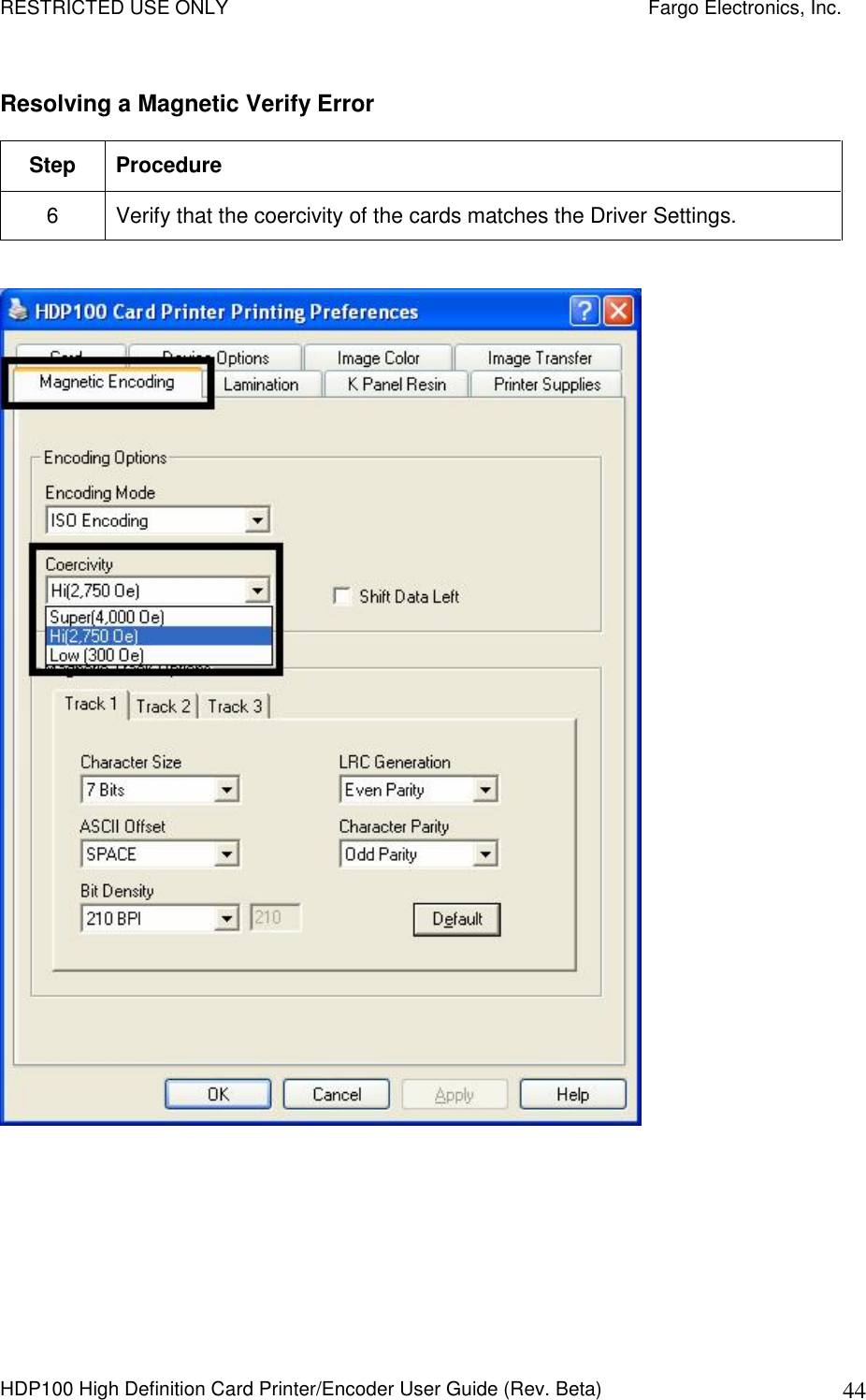
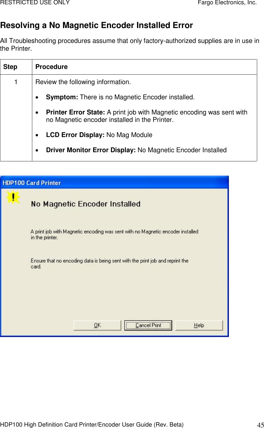
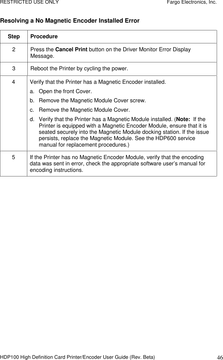
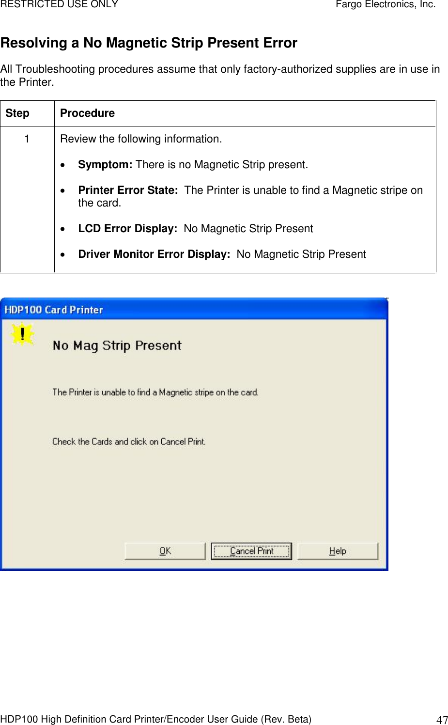
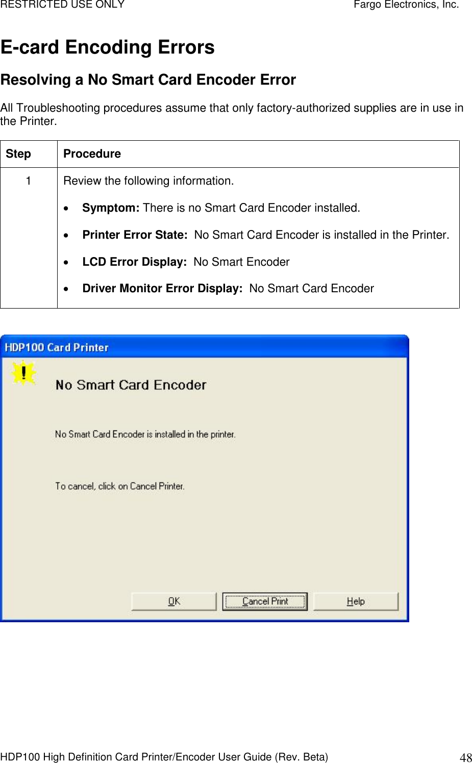
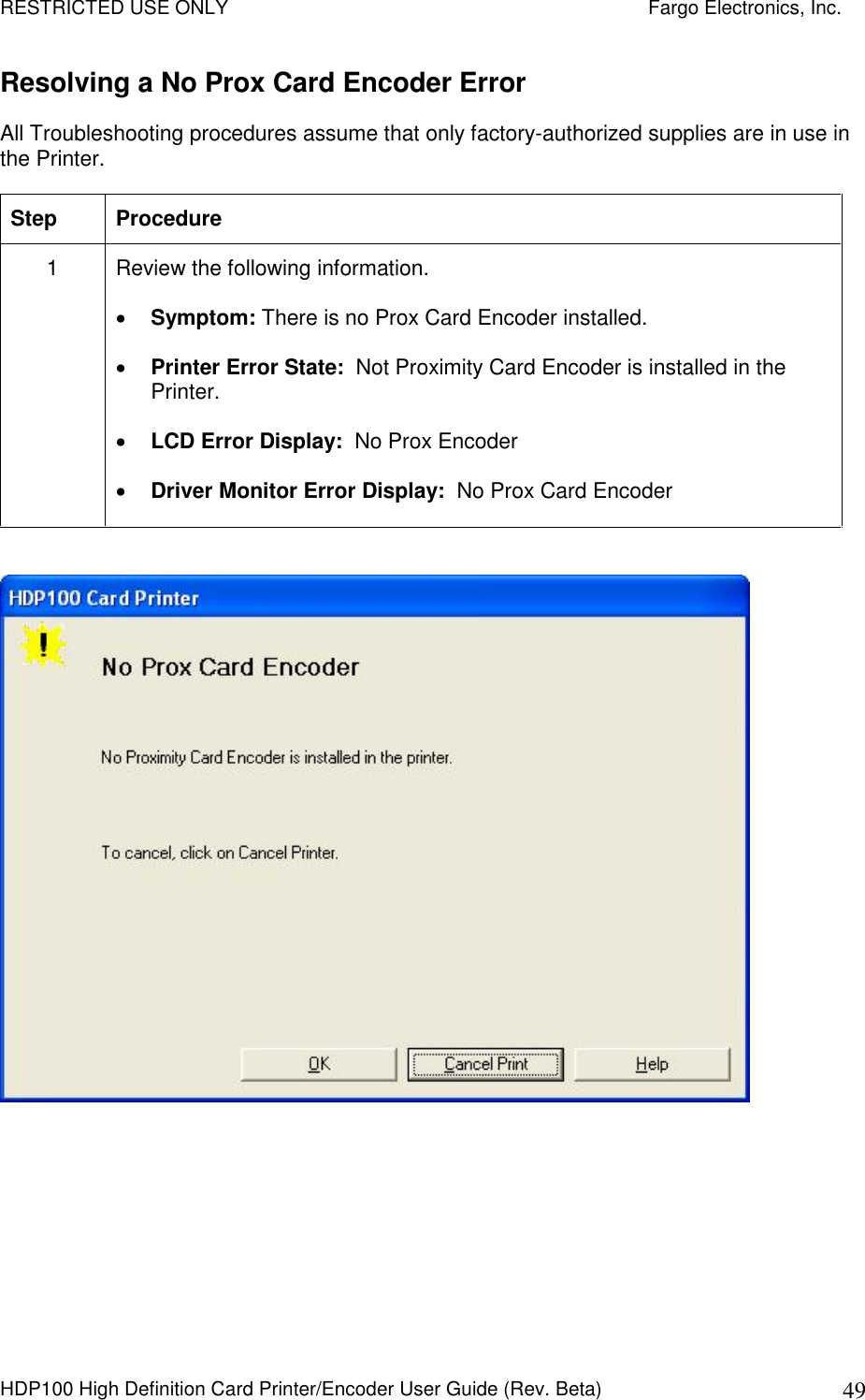
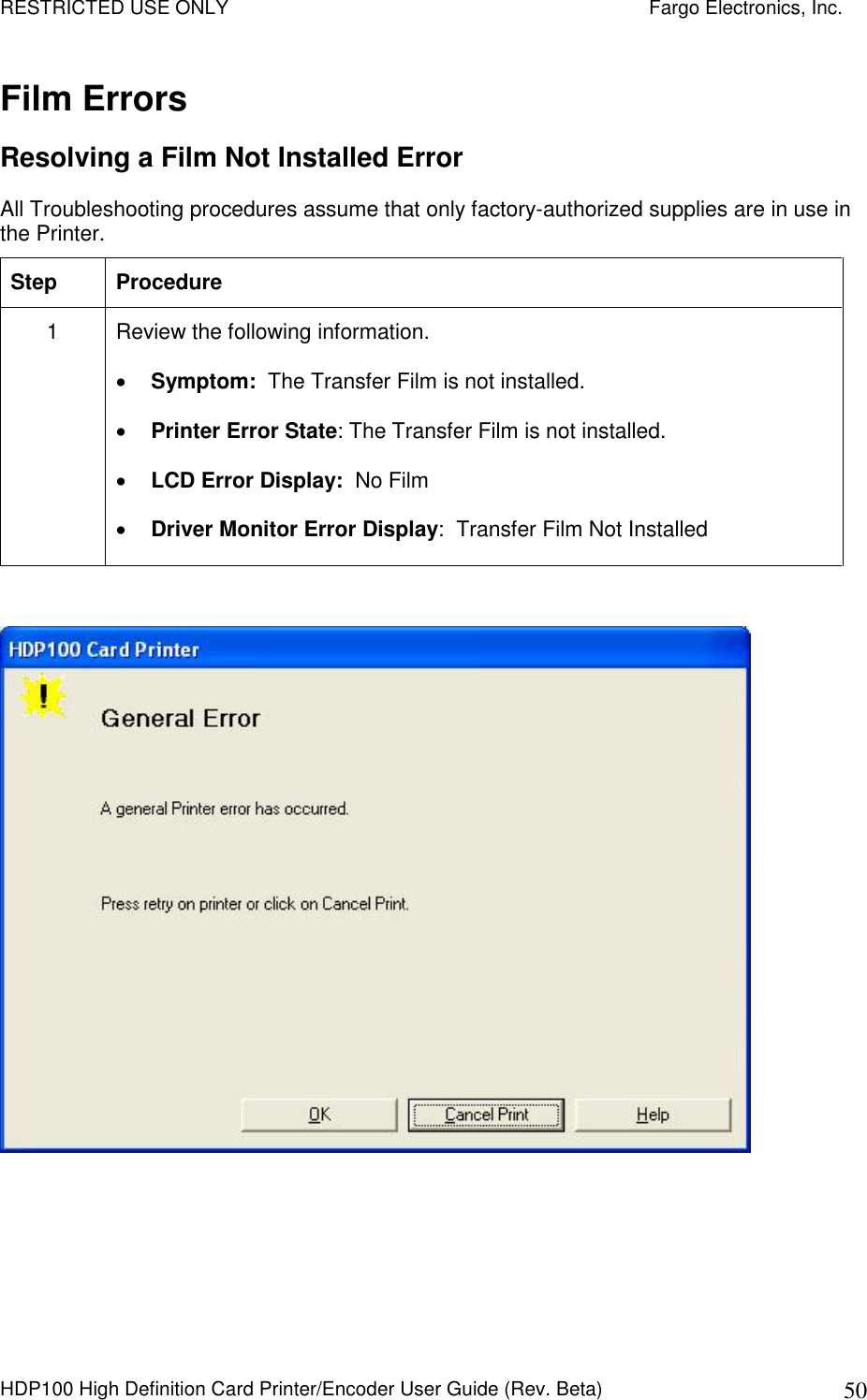
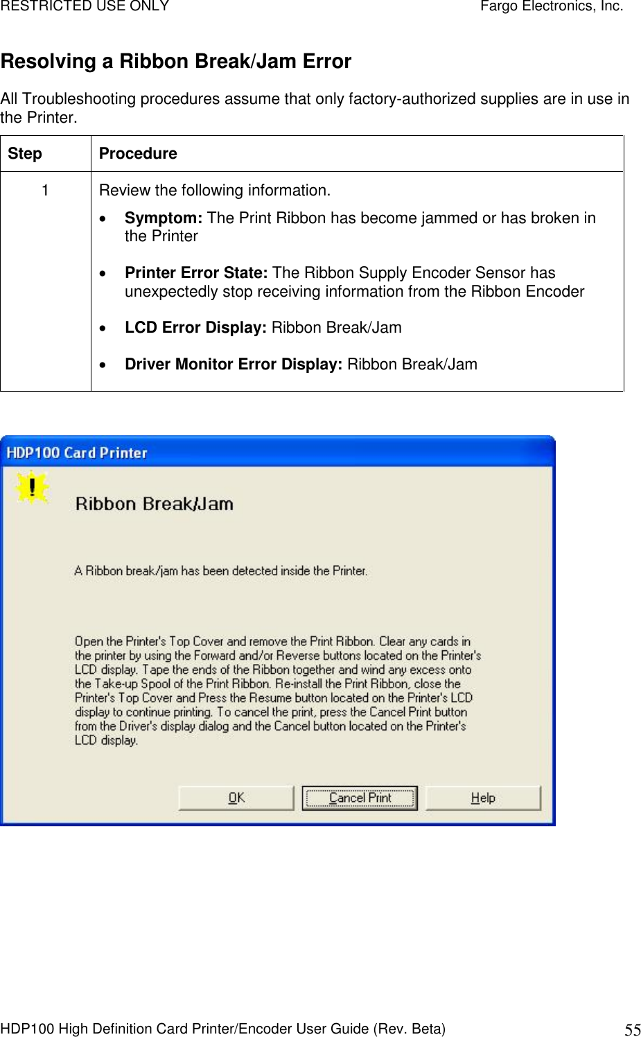
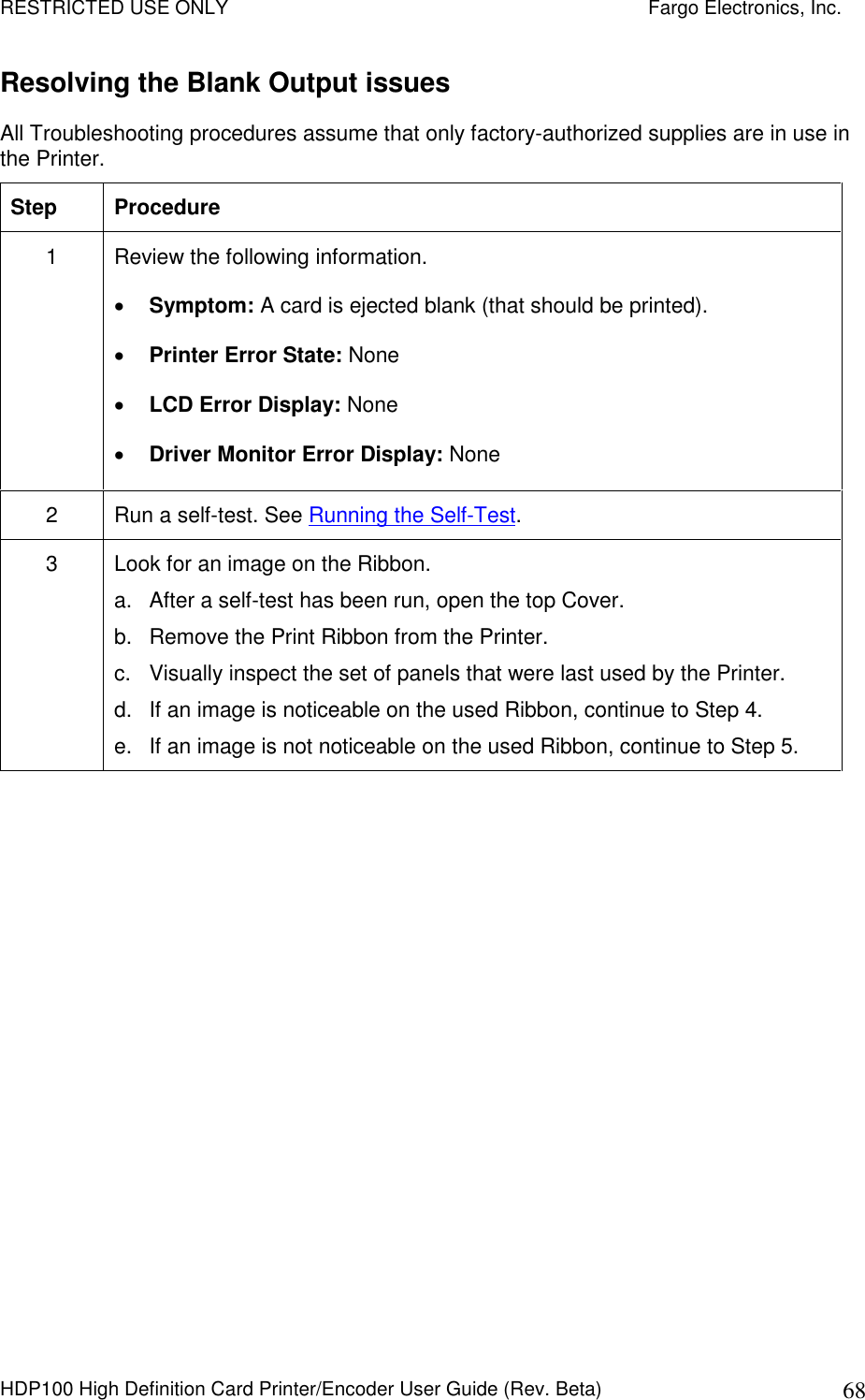
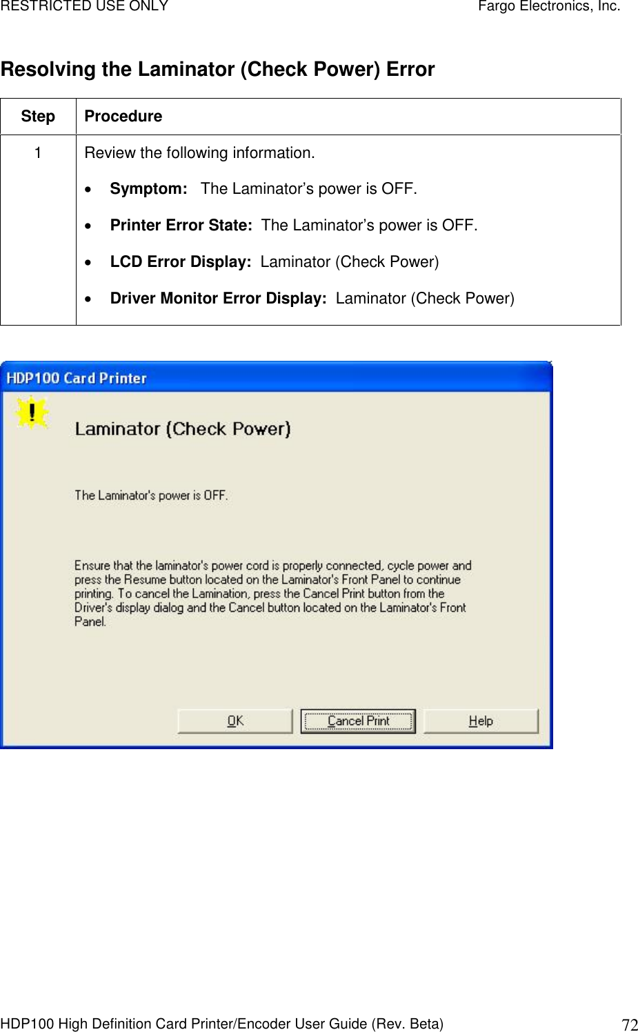
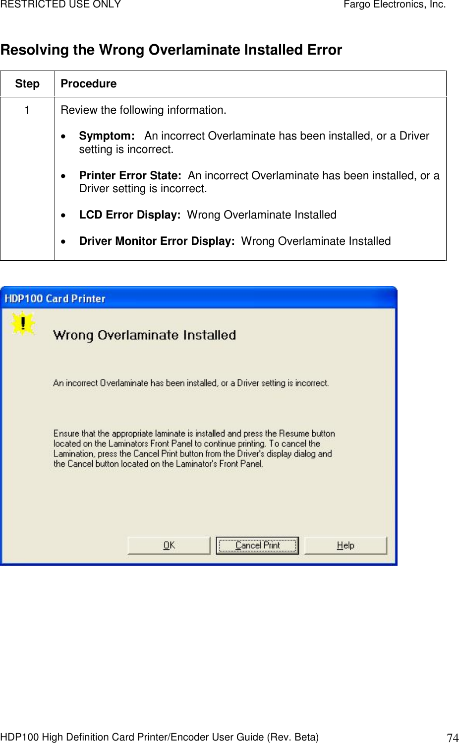
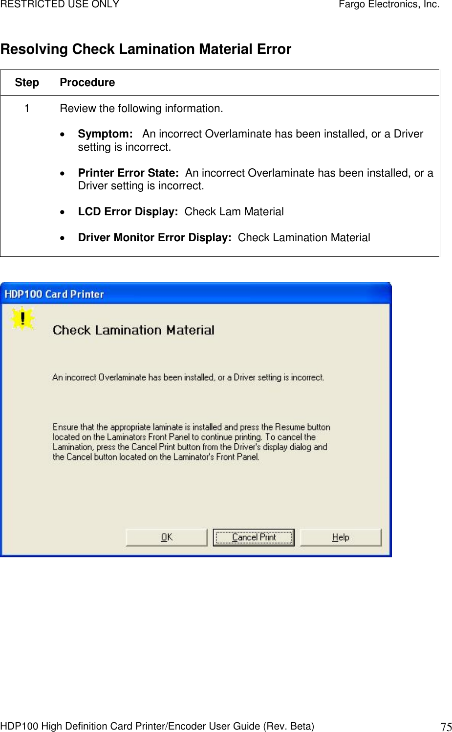
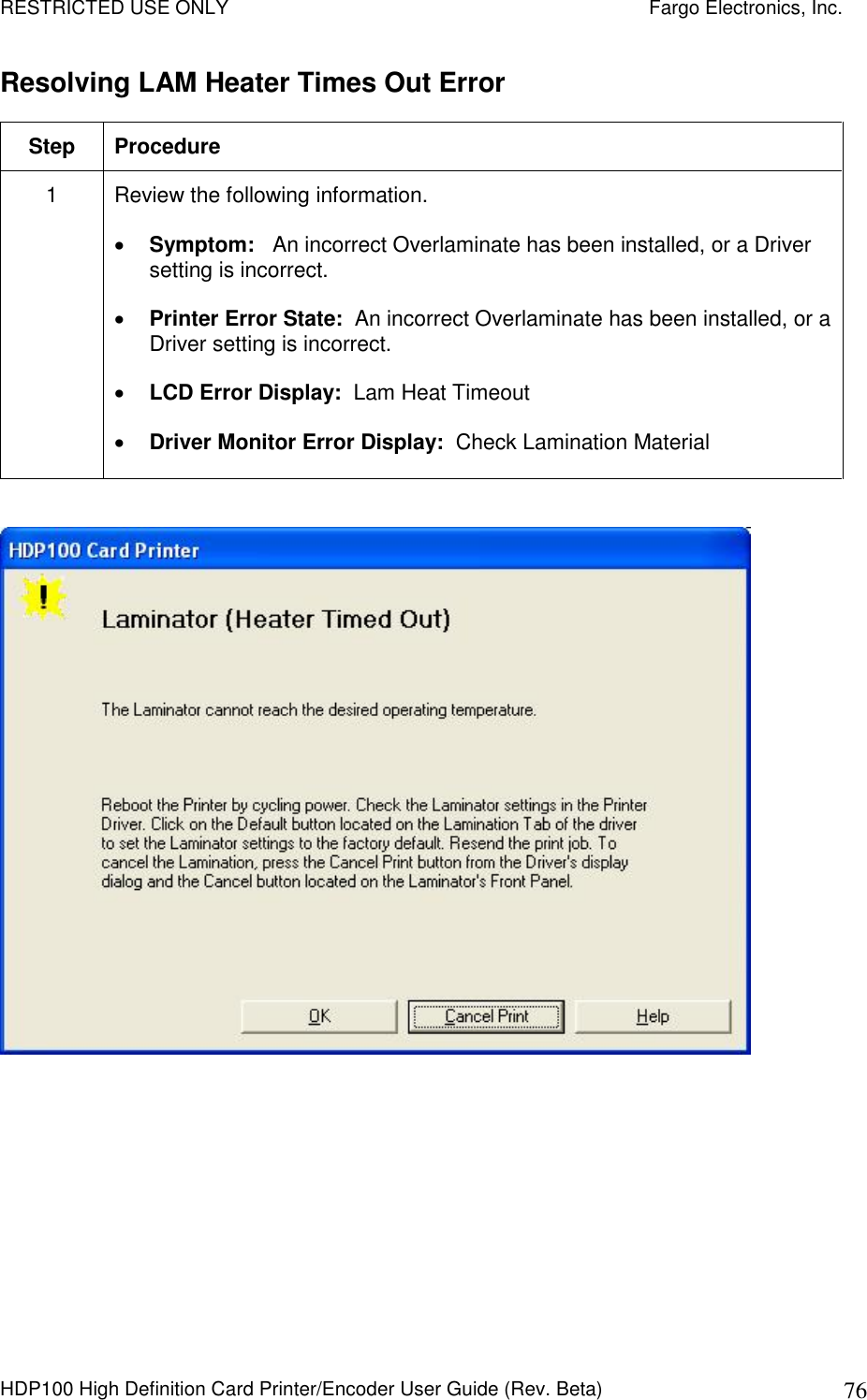
![RESTRICTED USE ONLY Fargo Electronics, Inc. HDP100 High Definition Card Printer/Encoder User Guide (Rev. Beta) 5 Troubleshooting the LCD Messages (continued) LCD Message Cause Solution Headlift Error The Printer was unable to raise or lower the Printhead. Verify that the head is not jammed. See Resolving a Headlift Motor or Sensor Error. Press RESUME to retry or CANCEL to abort. If the problem persists, call for technical assistance. HEAD LOADING An unrecoverable error occurred while printing. Contact technical support if this error repeats. Press CANCEL to abort this card. HEAD RESISTANCE LCD setting for head resistance is out of range. Enter a value for head resistance in the LCD Printer Setup menu. Reset the correct value according to the steps in the Troubleshooting Section. If this problem persists, call for technical assistance. HEAD SENSOR ERROR The Printhead Temperature Sensor is not functioning or is not connected properly. OR The Printhead is not cooling properly. If the problem persists, call for technical assistance. See Printing Process Errors. HEAD VOLTAGE ERROR A hardware fault has prevented setting the correct Printhead voltage. A default value will be used. Call for technical assistance. H1 Indicates that the Left Hopper is OFF. No action required. [H1] Indicates that the Left Hopper is ON. No action required. H2 Indicates that the Right Hopper is OFF. No action required. [H2] Indicates that the Right Hopper is ON. No action required. Continued on the next page](https://usermanual.wiki/Fargo-Electronics/OMNI5121/User-Guide-761728-Page-46.png)