Farpointe Data PYRAMID Proximity RFID Reader User Manual Installation guide
Farpointe Data Inc. Proximity RFID Reader Installation guide
Contents
- 1. Users Manual
- 2. Installation guide
- 3. Manual
Installation guide
Farpointe Data Readers
2177 Leghorn Street 01506-001 - Rev. 1.3
Mountain View, CA 94043-1605 USA 1 of 2
Tel: +1-650-964-2615 Fax: +1-650-988-6687
Web: www.pyramidseries.com E-mail: sales@pyramidseries.com
Installation Guide
Proximity Readers
This Installation Guide is intended for experienced installing technicians. It is a basic reference to ensure all
connections are properly made. See the appropriate Product Manual for detailed information on installing
Pyramid Series Readers or Cobra Readers (such as the P-300, P-500, P-640, P-700, or EM-30, EM-50,
EM-64). These documents may be downloaded from the Farpointe Data website found at
www.pyramidseries.com; under Support > Technical Documents.
NOTE: Installation and performance of a Pyramid Series Reader with HID compatibility (on operational fea-
tures) is identical to standard Pyramid Series Readers.
All Farpointe Data Readers are compliant with the following organizations:
FCC compliance Statement: This device complies with part 15 of the FCC rules. Operation is subject to the following two conditions:
(1) this device may not cause harmful interference, and
(2) this device must accept any interference received, including interference that may cause undesired operation.
1.0 Cable Requirements
All readers operate at up to 500 feet (152 m) of cable, using seven-conductor, shielded, stranded cable. Per
the Security Industry Association’s Wiegand specification, AWG 24 (such as Belden 9537) is the minimum
gauge required for data transfer in a 500-foot run length. However, the proper wire gauge to use must be
determined by the current draw requirements of the reader, the length of the cable run, and the voltage
applied to the reader.
If the reader is to be operated at 5 VDC, 5 VDC must be available at the reader (long cable runs have a volt-
age drop due to the resistance in the cable). A larger gauge of wire (having less resistance) or a separate
power supply near the reader may be required to ensure 5 VDC is available at the reader.
2.0 Output Formats
• Wiegand (industry standard 26-bit Wiegand and custom Wiegand formats)
• Magnetic Stripe (ABA Track II, clock and data, with card present)
3.0 Grounding
Shield (drain) continuity must run from the reader to the access panel. Shield (drain) and reader ground
must be tied together at the access panel and connect to an earth ground at one point.
4.0 Power
A reader may be powered by the access panel, so the reader is powered on when the access panel is pow-
ered on. However the best case is to power the reader by a separate, linear power supply.
5.0 Voltage
• Typically 5 to 14 VDC
NOTE: The user is cautioned that making changes not approved by Farpointe Data may void the user's
authority to use this equipment.
•••
Farpointe Data
2177 Leghorn Street 01506-001 - Rev. 1.3
Mountain View, CA 94043-1605 USA 2 of 2
Tel: +1-650-964-2615 Fax: +1-650-988-6687
Web: www.pyramidseries.com E-mail: sales@pyramidseries.com
Installation Guide
Proximity Readers
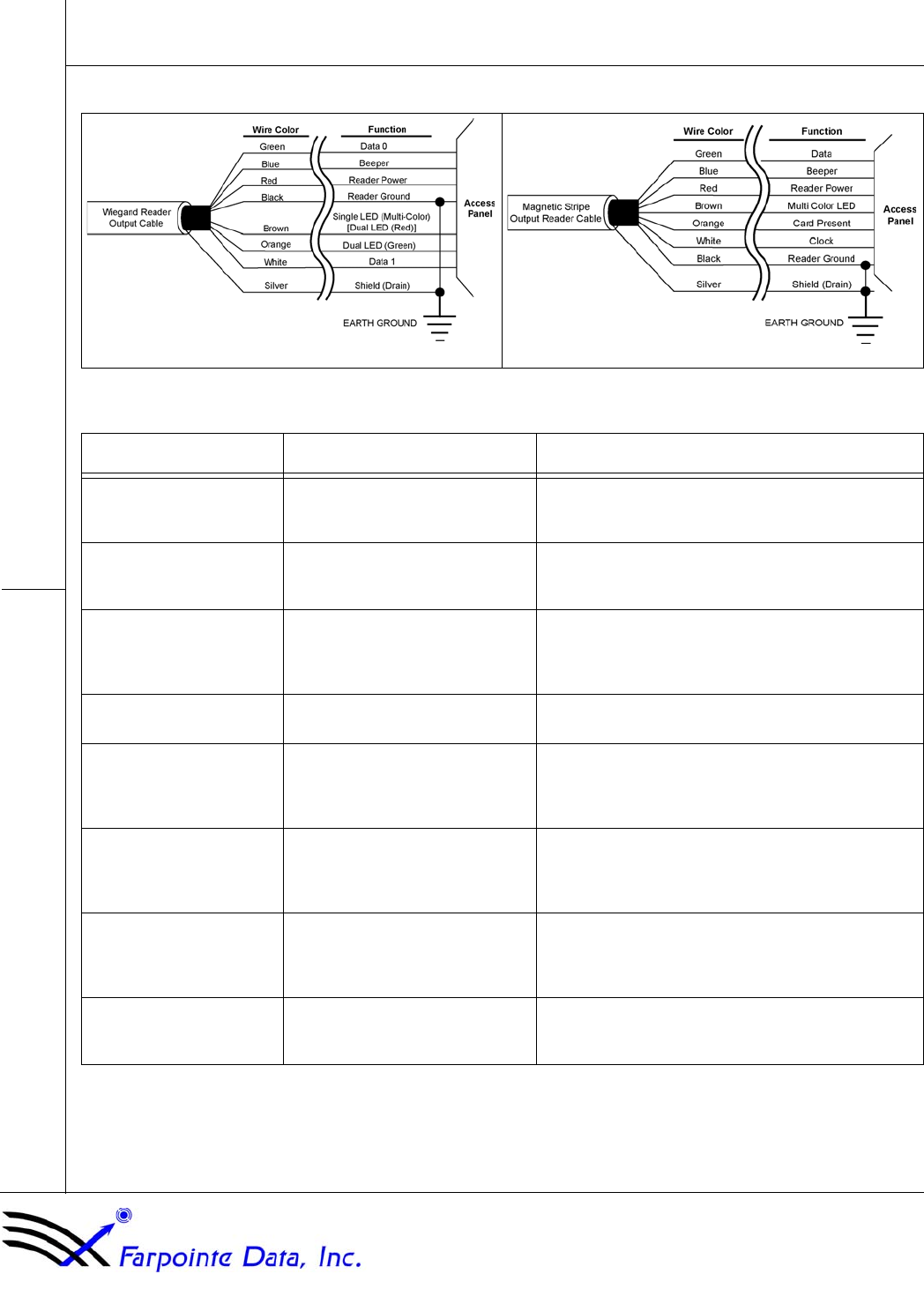
6.0 Reader Wiring
7.0 Troubleshooting the Reader Installation
Figure 1: Wiring Connections for Wiegand Output Figure 2: Wiring Connections for Magnetic Stripe Output
Problem Possible Cause Corrective Action
The reader does not recog-
nize a card/tag (no beep, no
LED flash)
1. One or more of the reader’s wir-
ing connections are incorrect Power down the reader/access panel and verify the wiring
connection are correct for the reader/access panel combi-
nation.
2. The reader is not receiving
proper power from the access
panel
Verify the voltage supplied to the reader is between 5 and
14 VDC.a
a. A supply voltage of 12 VDC at the reader is recommended for best operation.
3. The reader is mounted too close
to a device that radiates electro-
magnetic interference
Devices such as computer monitors radiate electromag-
netic interference that affects read range. When possible,
relocate either the reader or the device to provide greater
separation between the two.
4. You are using an incorrect type
of card. Make sure you are using an access card that is compatible
with the reader.
The reader has a short read
range. 1. The reader/access panel is not
properly grounded. Ensure there is a quality earth ground connection made to
the access panel. Refer to the access panel’s documenta-
tion for information regarding the earth ground connec-
tion.
2. The shield wire for the reader’s
cable has opened somewhere
between the reader and the
access panel.
Verify the shield line from the access panel to the reader is
one continuous, connected line. Refer to the access panel’s
documentation and verify the shield line is correctly con-
nected to the access panel.
3. The reader is mounted too close
to a device that radiates electro-
magnetic interference.
Devices such as computer monitors radiate electromag-
netic interference that affects read range. When possible,
relocate either the reader or the device to provide greater
separation between the two.
4. The power supply is generating
electromagnetic interference The power supply on the access panel must be a regu-
lated, linear supply. Do not use switching supplies as they
are often sources of electromagnetic interference.