Faurecia Clarion Electronics AVWCL1200 Digital Wireless Camera and Monitor System User Manual LA EE 2179E A EE 2179E A indd
Clarion Co Ltd Digital Wireless Camera and Monitor System LA EE 2179E A EE 2179E A indd
User Manual
Printed in Taiwan 2013/10 EE-2179
Thank you for purchasing this Clarion product.
Please fully read this Installation/Owner’s Manual before operating this equipment.
SAFETY PRECAUTIONS
When using this system, follow the precautions listed below.
WARNING
This device is a rear view camera intended for vehicle installation. Do not use it in any way other than its
intended use.
Doing so may result in smoke, fire, electric shock or injury.
Drive slowly while reversing.
Do not disassemble and/or modify the device.
Doing so may result in accident, fire, electric shock or malfunction.
Do not damage the camera cable.
Moisture or water may get inside the camera through the damaged part, possibly resulting in a malfunction or fire.
Never use the parts that are critical to the vehicle's safety* for mounting or grounding the device.
* Nuts and bolts in the steering system, seat rails, brake system, fuel tank, etc.
Doing so may result in loss of control, fire or traffic accident.
Never drive looking solely at the monitor.
This is an auxiliary device to supplement the driver's rear field of vision; it does not show all hazards or obstacles.
Actual distances and perceptions may differ and video images may be delayed, so be sure to visually check safety
while driving. Failure to do so creates the risk of hitting a person or object in the camera's blind spot, causing a serious
accident.
Do not use the device in a malfunctioning or abnormal state.
If no image is displayed, smoke is emitted or there is a strange smell, stop using the device immediately.
Continued use may result in an accident, fire or electric shock.
Do not allow any water or foreign objects to get inside the device.
If a foreign object or water gets inside the device, smoke or a strange smell is produced, or any other abnormality
occurs, stop using the device immediately and consult the dealer where it was purchased. Continued use may result in
an accident, fire or electric shock.
Disconnect the negative terminal of the battery before connecting the cables.
Failure to do so may result in electric shock or injury due to short-circuit.
Route the cables to avoid high-temperature areas.
The covering of the cables may melt, causing a short-circuit and resulting in an accident or fire. Pay particular attention
when routing the cables inside the engine compartment.
Mounting and removal of the device should be performed by a professional service technician.
Failure to do so may result in an accident or fire. Contact the dealer where the device was purchased.
After installing and connecting the device, check operation of the vehicle's electrical components*.
* Brakes, lights, horn, hazard lamps, blinkers, etc.
Malfunction may result in fire, electric shock or traffic accident.
If mounting of the device requires making a hole in the chassis, check the position of the pipes, tanks,
electrical wires, etc. and be sure to avoid interference or contact.
Damage to the pipes etc. may lead to fire or malfunction.
Route the cables and bundle them so that they do not interfere with driving operation.
If a cable coils round the steering column, gear lever, brake pedals, etc., it may lead to an accident.
When connecting the cables to a vehicle equipped with air bags, do not route the cables where they will affect
operation of the air bag system.
If the air bags do not work properly, it may result in an accident or injury.
Keep screws and other small parts out of the reach of small children.
Small parts may be swallowed accidentally. If there is any suspicion that this may have happened, seek medical
advice immediately.
CAUTION
The receiver is designed to be installed inside the vehicle's cabin. Do not install it in areas where it can get
wet.
Doing so may result in smoke, fire, electric shock or injury.
Do not subject the receiver to strong impact such as dropping it or hitting it.
This receiver utilizes precision electronic parts. Subjecting it to strong impact may result in malfunction or damage,
leading to fire or electric shock.
Remove the camera from the vehicle before using an automatic car wash (high pressure water).
Failure to do so may result in the camera becoming detached or getting damaged. If water gets inside the camera, it
may result in fire, electric shock or malfunction.
Check the mounting screws occasionally and tighten any that have come loose.
If the screws are loose, the device may become detached and fall off, hitting a passer-by and causing an accident.
Follow the instructions in the manual when mounting and connecting the camera and receiver.
Incorrect connection may result in fire or accident.
After mounting the camera and receiver, check that the monitor image is a mirror image.
Incorrect setup may mean that the monitor image is not horizontally flipped, resulting in accident.
The rear-view monitor image has the same right-left inversion as your vehicle's rearview mirrors. Depending
on the vehicle, the field and angle of view may differ.
Be sure to use the supplied accessories and specified components.
Using components other than those specified may lead to damage of the parts inside the device or the inability to
secure them firmly, resulting in them becoming detached and leading to an accident or malfunction.
After connecting the cables, secure them with clamps or insulating tape.
If the cables come into contact with the chassis, they will fray and short-circuit, leading to an accident or fire.
If a hole is made in the chassis to route the cables, use protective tubing or insulating grommet.
If the cables come into contact with the openings, they will fray and short-circuit, leading to an accident or fire.
If a hole is made in the chassis to mount the device or route the cables, seal the gap in the hole and the gap
between the hole and the cable with silicon adhesive or similar.
If exhaust gas or water gets inside the vehicle through the gap, it may result in an accident.
Route the cables so that they do not get caught in the chassis, screws, seat rails or other moving parts.
Damaged or short-circuited cables may result in an accident, electric shock or fire.
When mounting the camera on the vehicle, make sure that it does not protrude from the side or front/rear end
of the vehicle.
A protruding camera may hit a passer-by and cause an accident.
If the screws in the chassis are used to mount the device, be sure to tighten them securely.
Loose screws may result in an accident or malfunction.
Check the effect on medical electrical equipment.
This device is equipped with a wireless function.
If you use a cardiac pacemaker or other medical electronic device, be sure to check with the manufacturer or retailer
of the medical electrical device concerning the effect of radio waves.
Disclaimer
This product is intended to improve blind spot viewing while operating the vehicle and promoting safe
driving.
When signal interruption occurs due to the RF interference and/or environmental surroundings, the Clarion
wireless camera systems may experience image jump or/and video signal loss. When video signal loss
occurs, the following caution screen is displayed or sometimes a black screen will be shown to inform drivers
that the radio wave environment is not in good condition.
Clarion is not liable under any circumstances for the following.
Incidental, special, or consequential damage or loss that occurs directly or indirectly to this wireless camera system.
Inconveniences, damages and/or losses (including those due to the user’s improper use or incaution) caused by the
inability to view the camera image due to reasons/causes including the malfunctioning/defect of this wireless camera
system.
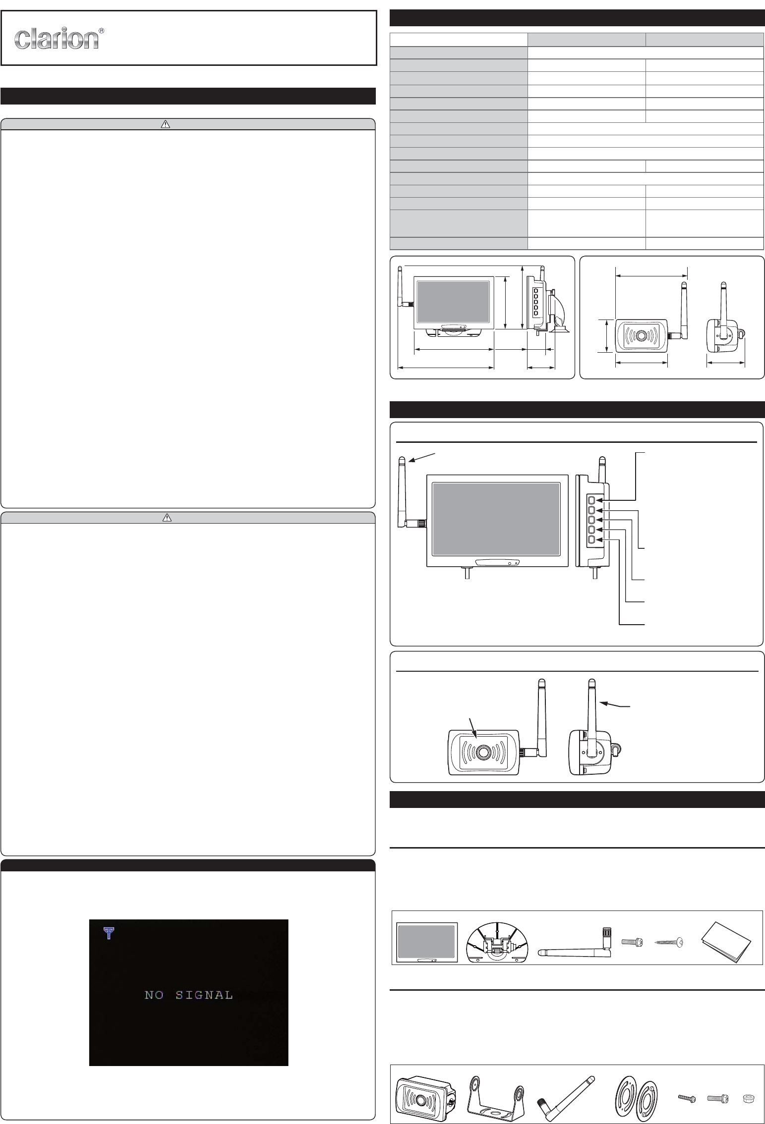
SPECIFICATIONS
Monitor with receiver Camera With Transmitter
Power supply voltage 12V/24V DC
Current consumption less than 330mA less than 150mA
Monitor Size 7 inch (Panel diagonal) -
View Angle 45 degree (H) / 45 degree (V) -
Image sensor - 1/3.6” CMOS camera
Angle of view - Horizontal 115°/ Vertical 85°
Modulation system FHSS (Frequency Hopping Spread Spectrum)
Transmission/Reception frequency 2.4GHz band
Channel Bandwidth 2MHz
Operating temperature range -10°C ~ +70°C -30°C ~ +70°C
Storage temperature range -40 ~ +85°C
Watertightness Non-watertight IP67
Vibration registance 4.4G 6.8G
External Dimensions
(Width x Depth x Height)
W: 174 mm (6-27/32”) x
D: 40.5 mm (1-19/32”) x
H: 113 mm (4-7/16”)
W: 80 mm (3-5/32”) x
D: 58.23 mm (2-19/16”) x
H: 50 mm (1-31/32”)
Weight 236g (0.52lbs) 300g (0.66lbs)
174 mm 40.5 mm
209.5 mm 59.5 mm
140 mm
113 mm
80 mm
110 mm
58.23 mm
50 mm
Note:
NAMES AND FUNCTIONS OF PARTS
Monitor with receiver (RX-Monitor)
[ Power ]/[ Menu ] Button
1) When camera signal is
being received.
Power on automatically
Press to enter the menu
2) No camera signal.
Press for power on
Press to enter the menu
Press at least 3 seconds
for power off
[ Right ] Button
menus
[ Left ] Button
Return to the previous menus
[ Up ] Button
Select Up
[ Down] Button
Select Down
Antenna
to the receiver.
Camera with transmitter
Antenna
Rotate the antenna and
fix securely to the
camera with transmitter.
Camera lens
PACKAGE CONTENTS
This product (system) consists of the following components.
In the event of any defect, contact the retailer where purchased.
Monitor with receiver included
1 RX Monitor (Power cable length: 2.9 m / 9.514 ft)................................................................................. 1
2 Adjustable bracket ................................................................................................................................. 1
3 Antenna .................................................................................................................................................. 1
4 Hexagon head bolts with built-in washer (M5 mm x 8 mm) .................................................................. 1
5 Self tapping screw (M3.5 mm X 10 mm) ................................................................................................ 5
6 Installation/Owner’s Manual .................................................................................................................. 1
123456
Camera with transmitter included
7 Camera with transmitter (Power cable length: 2.9 m / 9.514 ft) ............................................................ 1
8 Mounting bracket ................................................................................................................................... 1
9 Antenna .................................................................................................................................................. 1
0 Gasket .................................................................................................................................................... 2
! Hexagon head bolts with built-in washer (M3 mm X 8 mm) .................................................................. 5
@ Hexagon head bolts with built-in washer (M5 mm X 8 mm) .................................................................. 2
# Flanged nuts (M5 mm) ........................................................................................................................... 2
7890!@#
Digital Wireless Camera System
Installation/Owner’s Manual
2013
/
12
HOW TO INSTALL
How to attach the monitor with receiver
1.
place after removing protective tape from stand bottom.
2. Fix the stand with enclosed screws.
3. Assemble the monitor to the stand and adjust it to the correct viewing angle.
5 Self tapping screw
2 Adjustable bracket 4 Hexagon head bolts with built-in washer
How to mount the camera with transmitter
Never swin
g
the camera b
y
the cable or pull the cable. Doin
g
so ma
y
impair the
camera's waterti
g
htness or break the cable, resultin
g
in malfunction.
A
void mounting the camera where the lens will be exposed to dirt
(
mud splashes,
exhaust
f
umes, etc.
).
1. To prevent camera shake, make mounting holes in a solid
location
below. If the part is not strong enough, carry out appropriate
reinforcement.
2. After connecting the cables, adjust the mounting angle of the
camera so that the rear bumper or back end of the vehicle
appears in the monitor.
● Be sure to use the supplied screws to mount the
camera.
● If any screws are lost when mounting the camera, be
sure to use hexagon head bolts with built-in washer
(M3mm x 8mm). Do not under any circumstances use
screws that are longer than this. To ensure watertight-
ness, the screws in the camera case have a bag
structure. Use of long screws may damage the screw
thread and camera case, compromising watertightness.
WARNING
45 mm
0 Gasket
9 Antenna
Rotate the antenna and fix
securely to the receiver.
8 Mounting bracket
@ Hexagon head bolts
with built-in washer (M5 mm x 8 mm)
! Hexagon head bolts
with built-in washer (M3 mm x 8 mm)
! Hexagon head bolts with built-in washer (M3 mm x 8 mm)
# Flanged nuts (M5 mm)
Vehicle side : 5.5 mm hole (Two places)
PAIRING
The pairing function has been set at factory level so pairing is not required at the initial installation
stage. The pairing steps can be skipped in this case.
If the camera or monitor are replaced for any reason, then pairing must be completed as per the
instructions below. Pairing is also required each time you change Tractor/Trailer combinations.
1. Press the pairing button (on the rear of the monitor)
for four seconds.
2. The words "please Press Pair Key on Camera Side"
will appear on the monitor. A 30 second timer will then
count down. Please pair before 30 seconds elapses.
3. Pairing method
Pairing method depends on vehicle type and design
of vehicle wiring harness.
Installation Condition Pairing method
(1) - Trailer with tractor user
- Reverse gear signal is enabled at rear of
a vehicle
For tractor and trailer applications that can
get reverse gear signal at the rear of a
vehicle, it is recommended to connect the
camera pairing wire (Brown) to the +12V
parking light circuit.
To begin the pairing process, make sure
the parking lights are off and the vehicle is
in reverse gear. Turn the parking lights on
and begin the pairing process.
(2) - Users other than (1) For users under other conditions, connect
the pairing line to +12V/24V (ACC or
illumination active) line for one second.
When pairing is completed, disconnect and
insulate the end of this cable with insulating
tape.
4. The camera video will appear on the monitor and pairing is complete.
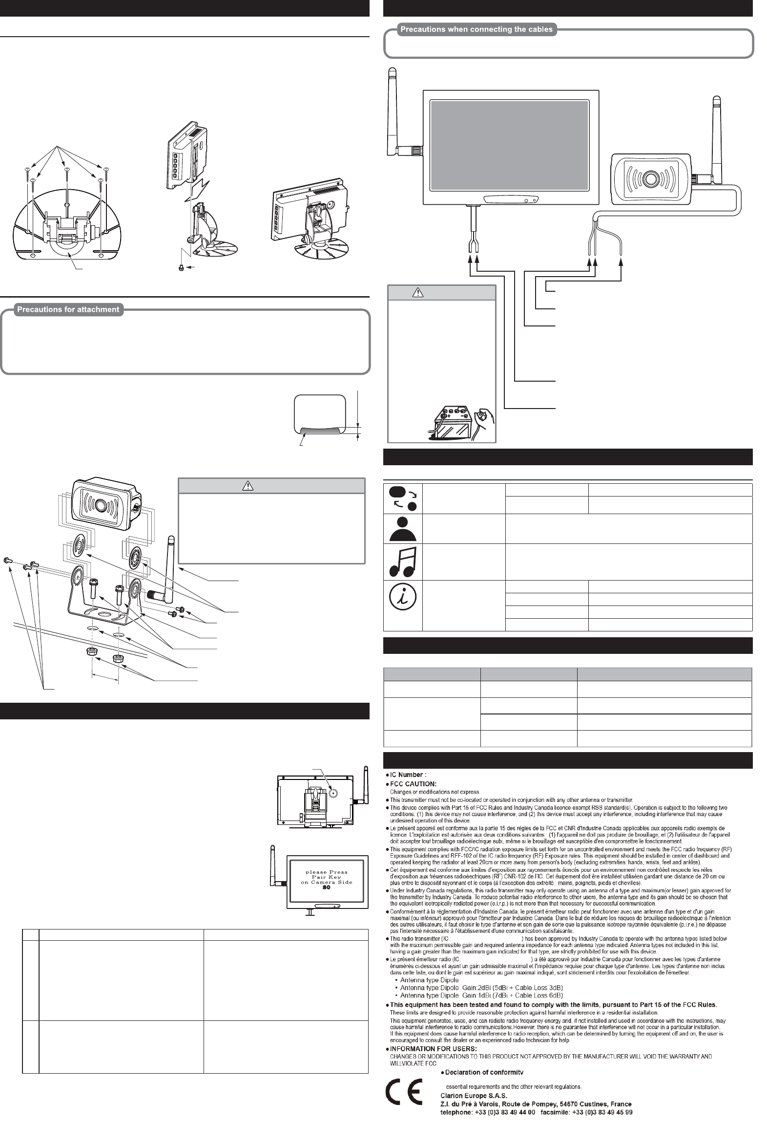
WIRING AND CONNECTIONS
To prevent short-circuiting, check the connections again be
f
ore connecting the battery.
RedBrown Black
Camera with transmitter
Ground (Negative)
Connect to chassis ground.
Ground (Negative)
Connect to the metal part of the vehicle.
● Do not connect the power
cable (red) of either the
transmitter or the receiver to
the +B line (permanent
power supply) as this may
lead to a flat battery.
● Disconnect the negative
terminal of the battery before
connecting the cables.
Failure to do so may lead to
electric shock or injury due to
short-circuit. It may also lead
to damage to the system
components due to
short-circuit.
WARNING
RedBlack
Reverse or Parking light
Please refer to item 3. of PAIRING section.
ACC+
Connect to a positive power supply that can be turned on and
off with the ignition key.
Pairing
Please refer to the item 3. of PAIRING section.
Monitor with receiver
MONITOR SETUP
MENU
Input mode setting INPUT Must be CCD
INFORMATION View the current parameters
Color adjustment Adjust the display parameters
Audio adjustments Not applicable to this system.
System Information SLEEP TIMER Set to 0
WIDE SCREEN Set to WIDE
LANGUAGE Adjusting language
RESET Restore the initial settings
TROUBLE SHOOTING
The following situations may not be malfunctions. Check once more before requesting repairs.
Symptom Cause Remedy
There is no image (Nothing
appears on the monitor)
The receiver is not connected
correctly
Check the receiver’s connections and connect the re-
ceiver correctly
There is no image (“No Sig-
nal” is continuously displayed
on the monitor)
The camera is not connected
correctly
Check the camera’s connections and connect the cam-
era correctly
The surrounding radio wave
signal strength is weak
Move to a different place and check if the image ap-
pears
The image cuts out The surrounding radio wave
signal strength is weak
Move to a different place and check if the image ap-
pears
OTHER
IC Number :419C-EE2179
FCC CAUTION:
Changes or modifications not express.
This transmitter must not be co-located or operated in conjunction with any other antenna or transmitter.
This device complies with Part 15 of FCC Rules and Industry Canada licence-exempt RSS standard(s). Operation is subject to the following two
conditions: (1) this device may not cause interference, and (2) this device must accept any interference, including interference that may cause
undesired operation of this device.
This equipment complies with FCC/IC radiation exposure limits set forth for an uncontrolled environment and meets the FCC radio frequency (RF)
Exposure Guidelines and RFF-102 of the IC radio frequency (RF) Exposure rules. This equipment should be installed and operated keeping the
radiator at least 20cm or more away from person's body (excluding extremities: hands, wrists, feet and ankles).
Under Industry Canada regulations, this radio transmitter may only operate using an antenna of a type and maximum(or lesser) gain approved for
the transmitter by Industry Canada. To reduce potential radio interference to other users, the antenna type and its gain should be so chosen that
the equivalent isotropically radiated power (e.i.r.p.) is not more than that necessary for successful communication.
This radio transmitter IC Number (IC Number: 419C-EE2179, 419C-CC3500) has been approved by Industry Canada to operate with the antenna
types listed below with the maximum permissible gain and required antenna impedance for each antenna type indicated. Antenna types not
included in this list, having a gain greater than the maximum gain indicated for that type, are strictly prohibited for use with this device.
Antenna type:Dipole Gain:2dBi Model:EE2179
Antenna type:Dipole Gain:2dBi (5dBi + Cable Loss 3dB) Model:EE2179
Antenna type:Dipole Gain:1dBi (7dBi + Cable Loss 6dB) Model:EE2179
This equipment has been tested and found to comply with the limits, pursuant to Part 15 of the FCC Rules.
These limits are designed to provide reasonable protection against harmful interference in a residential installation.
This equipment generates, uses, and can radiate radio frequency energy and, if not installed and used in accordance with the instructions, may
cause harmful interference to radio communications.However, there is no guarantee that interference will not occur in a particular installation.
If this equipment does cause harmful interference to radio reception, which can be determined by turning the equipment off and on, the user is
encouraged to consult the dealer or an experienced radio technician for help.
INFORMATION FOR USERS:
CHANGES OR MODIFICATIONS TO THIS PRODUCT NOT APPROVED BY THE MANUFACTURER WILL VOID THE WARRANTY AND
WILLVIOLATE FCC
Rear bumper or rear end
of the vehicle
About 7mm
Monitor screen
Pairing Button
+12V/24
V
419C-AVWCL1200
419C-AVWCL1200
419C-AVWCL1200
Gain:4dBi Model:EE-2179
Model:EE-2179
Model:EE-2179
We Clarion declares that the
p
roduct EE-2179 is followin
g
the
p
rovision of Directive 1999/5/EC with the