Faurecia Clarion Electronics
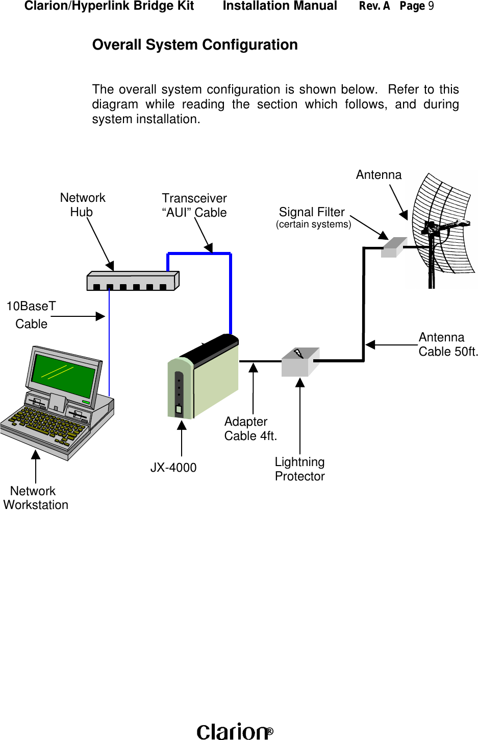
 JX4000 User Manual MANUAL FCC NONAMPLIFIED3

Clarion Co Ltd MANUAL FCC NONAMPLIFIED3

New User Manual

Clarion/Hyperlink Bridge Kit        Installation Manual      Rev. A   Page 1 Clarion JX-400010 Mbit/sec WIRELESS TRANSCEIVERClarion/Hyperlink Wireless LAN Bridge KitInstallation ManualWireless LAN DivisionClarion Corporation of America
Clarion/Hyperlink Bridge Kit        Installation Manual      Rev. A   Page 2 Copyright © 1996, Clarion Corporation of America. All rights reserved. No part ofthe contents of this document may be transmitted or reproduced in any form orby any means without the written permission of Clarion Corporation of America.Portions Copyright © 1998, Hyperlink Technologies, Inc. All rights reservedWARNINGSThe manufacturer assumes no responsibility for damage caused by interferencedue to this equipment.
Clarion/Hyperlink Bridge Kit        Installation Manual      Rev. A   Page 3 ContentsFCC Radio Interference Statement   4Introduction   5Features of the JX4000   5Types of Installations   6System Requirements   7Kit Contents   7Tools Required   7JX-4000 Front & Rear Panel Features   8Overall System Configuration   9Antenna System Connections 10Surveying the Antenna Site 10Preparing for System Installation 11Mounting & Cabling the Antenna System 11LED Diagnostic Display 13Clarion JX-4000 Specifications 14APPENDICESAntenna Mounting Instructions       Appendix A
Clarion/Hyperlink Bridge Kit        Installation Manual      Rev. A   Page 4 Radio Frequency Interference StatementUSA - Federal Communications Commission (FCC): This device complieswith Part 15 of FCC Rules. Operation of this device is subject to the followingtwo conditions:This device may not cause harmful interference.This device must accept any interference that may cause undesired operation.Information to User: This device must be installed and used in strict accordancewith the manufacturer's instructions. However, there is no guarantee thatinterference to radio communications will not occur in a particular commercialinstallation. If this device does cause interference, which can be determined byturning the host equipment off and on, the user is encouraged to consult theinstruction manual of the host equipment or the local device supplier. In case thedevice does cause harmful interference with an authorized radio service, theuser/operator shall promptly stop operating the device until harmful interferencehas been eliminated.The manufacturer is not responsible for any radio or television interferencecaused by unauthorized modification of this device or the substitution orattachment of connecting cables and equipment other than those supplied. Thecorrection of interference caused by such unauthorized modification, substitutionor attachment will be the responsibility of the user.
Clarion/Hyperlink Bridge Kit        Installation Manual      Rev. A   Page 5 IntroductionThe Clarion JX-4000 is a wireless transceiver providing 10 Mbit/sec burst datarate to support wireless connections in IEEE 802.3 and Ethernet II (TCP/IP)LAN.  Equipped with a Hyperlink Extended Range Antenna System, the JX-4000offers a high-performance long-range building-to-building network bridge.The JX-4000 functions as an Ethernet MAU. It uses a state-of-the-art spreadspectrum technology to implement robust 10 Mbps burst transmission. It alsoactualizes efficient utilization of frame buffers and coordination of RF and wiredinterface traffic to maintain high throughput.The JX-4000 offers true “Plug and Play” installation.  No additional driversoftware is required for operation. That is, the JX-4000 can be connected notonly to a computer but also to a hub or to a router.FEATURES OF THE JX-4000The Clarion JX-4000 has the following features:• Full wireless Ethernet 10 Mbps data rate.• State-of-the-art spread spectrum technology providesreliable, secure, long range, radio link operation.• True “Plug and Play” installation for compatibility with all802.3 and Ethernet II LAN devices, all operatingsystems and all protocol stacks.
Clarion/Hyperlink Bridge Kit        Installation Manual      Rev. A   Page 6 Types of InstallationsThe type of application will determine which type of kit to install:Building-to-Building or Tower-to-Tower: Typically these installations willtypically require directional Yagi or Grid Antenna kits.Central Node in a Multipoint Network or Mobile Network: This type ofinstallation typically requires an Omni Directional Kit at the central node for 360degree coverage.System RequirementsThe Clarion/HyperGain™ Extended Range Bridge Kit provides a complete plug-
Clarion/Hyperlink Bridge Kit        Installation Manual      Rev. A   Page 7 and-play solution for linking buildings in an outdoor environment.  All you need toadd is suitable masts or towers and some basic site planning.  Please read thismanual in its entirety before beginning the installation.Kit Contents:Each Kit contains the following items:Clarion JX-4000 Radio and DC Power SupplyHyperGain Antenna (Omni, Yagi, or Grid)Interference Filter (On Certain Systems)HyperGain Lightning Protector50 ft. Antenna Cable4 ft. Jumper CableMounting HardwareSealant TapeManualTools Required:7/16" open-end wrench or Adjustable Wrench#12-10 AWG or similar wire (for grounding)Wire Cutter / StripperPliersOther Required Equipment:Suitable mast or tower hardwareAUI Transceiver CableAUI-equipped Network Hub or CardOther Helpful Equipment and Tools:Cellular telephones or Walkie-talkiesBinocularsCompassHandheld GPS
Clarion/Hyperlink Bridge Kit        Installation Manual      Rev. A   Page 8 JX-4000  Front and rear Panel FeaturesInternal antenna(inside of the topcover)MAU portExternal antenna portDC 6.2V portMAU LEDTX LEDRX LEDPower LEDPower SwitchFCC Certification label(bottom)
Clarion/Hyperlink Bridge Kit        Installation Manual      Rev. A   Page 9 Overall System ConfigurationThe overall system configuration is shown below.  Refer to thisdiagram while reading the section which follows, and duringsystem installation.Network   Hub  Transceiver “AUI” Cable10BaseTCableJX-4000AdapterCable 4ft.LightningProtectorAntennaCable 50ft.Antenna  NetworkWorkstation Signal Filter(certain systems)
Clarion/Hyperlink Bridge Kit        Installation Manual      Rev. A   Page 10 ANTENNA SYSTEM CONNECTIONWarning The JX-4000 may only be operated using one of theapproved antenna kits described herein.  All antennasystem components are equipped with unique connectors.Although these connectors may look similar to standardtypes they are not compatible with them.  Attempting toattach standard connectors to system components cancause damage to the connectors and attached equipment.In addition, the JX-4000 External antenna port is equippedwith a special Antenna recognition function which disablesthe transmit function in the event a non-approved antennasystem is connected to the radio.Surveying the Antenna SiteBefore beginning system installation, emphasis should be placed on systemplanning.  It is important that no large obstructions exist near the antenna, suchas retaining walls, chimneys, air-conditioning units or other antenna masts.These types of objects can have an impact on the antenna system performance.Plan to mount the antenna as high as possible.  You will need enough mast toelevate the antenna approximately 15 feet above the roof or above anyobstruction that might be in the antenna's signal path.You will need to identify the location where the antenna cable will be routed.  Ifyou run the antenna cable through the roof, a water-proof fitting will be required.Consult a building contractor or licensed electrician to help you with the routing ifnecessary.  Take note of the length of the mast you will need and the type ofmounting hardware required. The amplified antenna kit is shipped with U-Boltmounting hardware which should be ideal for mounting the antenna andamplifier to most types of mast.  Also, make plans on how you are going to talkto the person at the remote antenna while you are going through the antennaalignment procedure.  For example, cellular phones or walkie talkies can beused.
Clarion/Hyperlink Bridge Kit        Installation Manual      Rev. A   Page 11 Preparing for System InstallationWarning:  These antennas are designed to be mounted in open areas suchas rooftops or building exterior walls.  They are designed to be installed atleast 6 feet away from areas occupied by people.  During systemoperation, always keep the antenna at least 1 foot away from your head.Warning:  Before performing the following steps make certain that thereare not any power lines within 50 ft.  If the mast should fall, either whileinstalling or during operation, contact with any power lines will be fatal orresult in a fire.The Antennas are designed to be mounted on an aluminum or steel mast with adiameter from 1-1/4 inches to 2-1/8 inches.  A larger diameter mast would besuggested for a more durable installation.  The system includes a 50 footantenna cable.Note:  The antenna cable has  proprietary connectors at each end.Although these connectors resemble standard “N” type connectors, theywill not mate with standard “N” connectors.  Never attempt to attach adevice which is not supplied with the kit as it can cause severe damage tothe connectors.In addition to the kit contents, you will need a ground wire and wire ties.Mounting and Cabling the Antenna:Note:  Different model antenna kits have different mounting requirements andprocedures.  Refer to Appendix A in this manual for antenna mounting details.1. Attach the mast mounting hardware to a  solid structure on your building(e.g., the roof itself, concrete bulkhead, vent pipe).2. Using the included mounting hardware, secure the antenna to the topsection of the mast (see Appendix A for details).3. If the kit contains a signal filter, then install the filter in-line between the 50 ft.cable and the antenna.  Otherwise, screw one end of the 50 ft. directly ontothe antenna.4. Apply the included sealant tape around the joined connectors to preventcorrosion from the weather.  Wrap the entire connection, overlapping eachlayer slightly to ensure a weather-tight seal.
Clarion/Hyperlink Bridge Kit        Installation Manual      Rev. A   Page 12 5. Attach the one end of the antenna ground cable to the antenna mountingbracket or U-bolt and the other end to a building ground.6. Very carefully raise the mast and loosely secure it with the mast mountinghardware.  Use the plastic wire ties to tie the antenna cable to the mastevery six to twelve inches.7. Aim the directional antenna in the direction of the building you will be linkedto.  The omni-directional antennas should be mounted vertically and do notneed to be aimed as they radiate in a 360 degree pattern.8. Tighten the mast mounting screws.  Do not do anything that would make itdifficult to change the position of the antenna. It may be necessary toreposition the antennas while aiming them.9. Route the antenna cable along the roof to the point where it enters thebuilding.  From the inside, pull the cable through the hole and take up anyexcess slack.10. Attach the end of the 50 ft. antenna cable to the Lightning  Protector.  Attachthe 4 foot adapter cable between the Lightning Protector and the JX-4000.11. Attach a second ground wire to the ground lug on the Lightning Protectorand to a good building ground.12. Connect the JX-4000 to an “AUI-equipped” network  hub using an “AUI”transceiver cable.  A nearby network-connected workstation would be usefulduring system installation to verify proper operation.12. Plug the included 6.2 VDC power supply into the JX-4000 and then into thebuilding's AC power.  Never use a power supply other than the one shippedwith the system as it may cause damage to the radio.  It is furtherrecommended that the AC connection be through a commercially available"surge" protector power strip.
Clarion/Hyperlink Bridge Kit        Installation Manual      Rev. A   Page 13 LED Diagnostic DisplayDuring power-up, the front panel LEDs on the JX-4000 provide some diagnosticinformation.  Refer to the table below for LED diagnostic information.Label Color DescriptionMAU Green Indicates MAU signal (upload or download) is active.TX Red 1. During the power-up cycle, it blinks on and off slowlyfive times in approximately one second to indicate thatthe firmware has passed its integrity; or, it flashes onand off very rapidly for four or five seconds to indicatethat the firmware has been damaged. No indicationdescribed above is available in some case of hardwarefailure.2. After normal power-up cycle, it Indicates radiotransmission.3. During the firmware-uploaded cycle ; referdescription attached on the new firmware.RX Green 1. Indicates radio signal detection.2. Sometimes flashes even if no true signal receivesbecause of optimized false alarm rate.Power Red 1. It turns on at approximately 1/4 second after applyingthe power to indicate activation of the unit.2. If the hardware check sequence fails, it turns offautomatically at approximately 5 seconds after poweron.
Clarion/Hyperlink Bridge Kit        Installation Manual      Rev. A   Page 14 JX-4000  SpecificationsFrequency Range: 2400-2483.5 MHz ISM bandCarrier Frequency: 2436.07 MHzModulation Type: Direct Sequence Spread SpectrumChip Modulation: BPSK, 32 McpsProcessing Gain: 12dB (Nominal)Communication Method: Half DuplexChannel Access Method: SS-P-CSMA1Type of Interface: MAU (driven by AUI)Datalink Interface: IEEE802.3 or Ethernet II MACNetwork Addressing: derived from attached NIC  (Note-1)RF MAC Protocol: Radio encapsulation of IEEE802.3  or Ethernet II MAC frame.Network Topology: Peer to peerDimensions: 148mm(W) × 210mm(D) × 75mm(H)Power Requirement: +6.2VDC @ 2.0A max.Operating Temperature: 0 ~ +40 CStorage Temperature: -20 ~ +60 CHumidity: 0%  ~ 90%1.  Note 1 JX-4000 has its own MAC address for configuration of operatingparameters. JX-4000 also memorizes single MAC address of attachedNetwork Interface Card(s) for re-transmission protocol.                             1 Spread Spectrum p-persistent CSMA
Appendix AAntenna Mounting Instructions
Mounting Instructions - HG2408U Omnidirectional AntennaThe included bracket should be used to attach the antenna to a standard antenna mastor tower leg.  Proper positioning of the brackets is shown in the following diagram.  For best results, first attach the bracket to the tower or structure using the included V-bolt.  Then, install the antenna into the bracket and lock in place with the integral bolt.Note that the bracket should only be tightened around the aluminum base, and not thefiberglass radome  of the antenna.
Mounting Instructions - HyperGain HG2414Y Directional Yagi AntennaYagi antennas are mounted using the included U-Bolts, Nuts, and Lock Washers as shown in thefollowing illustration:The antenna should be aimed as shown, in the direction of the other end of the wireless link.
Mounting Instructions - HyperGain HG2415Y Radome Enclosed Yagi AntennaThe antenna can be mounted to a mast or directly to an exterior wall as shown.  The included U-boltsshould be used for mast mounting.  Note that in either case, the metal backing plate should be placeddirectly behind the plastic flange in order to provide greater stability.

Navigation menu