Fego Precision Co TR110BL RF Transmiter User Manual 5 Users manual 1
Fego Precision Industrial Co Ltd RF Transmiter 5 Users manual 1
Contents
- 1. 5.Users manual-1
- 2. 5.Users manual-2
5.Users manual-1

Manual design and all elements of manual design are protected by U.S. Fede
This product is protected by United States Federal and/or State Law, including Patent, Trademark and/or Copyright laws.
ral and/or State Law, including Patent, Trademark and/or Copyright Laws.

warranty is for one (1) year from the date of purchase from an authorized Minka-Aire dealer.
This warranty is only valid to the original purchaser or user against all defects in material and workmanship (light bulbs
excluded) for one (1) full year. Additionally, Minka-Aire warrants the motor only for the lifetime of the Minka Aire ceiling
fan (excluding wall controls and electrical components), to the original purchaser or user.
The warranty is voided with the use of any non- Minka-Aire electrical devices, E.g., wall controls or electrical dimmer switches, etc...
The warranty is void once the original purchaser or user ceases to own the fan or the fan is moved from its original point of installation.
The warranty is void with the use of any hanger bracket (non-Minka Aire or non-fan specific) other than the hanger bracket supplied & installed
with this specific fan.

To obtain the name of the Minka-Aire authorized dealer nearest you call the Minka-Aire customer care department at 1-800-307-3267, or
contact Minka-Aire through www.minkagroup.net and write to: “Ask Mr. Minka” to answer any questions or if you require assistance.
To obtain warranty servic during the warranty period, the purchaser should return the fan with the sales receipt to the original place of
purchase. The authorized Minka-Aire dealer, at its sole discretion, will either repair or replace the fan after verifying the legitimacy of the warranty
claim. Replacement is subject to availability of the same model. If the model is unavailable it will be replaced by one of equal value. This is a limited
warranty; the original purchaser or user is responsible for the cost of removal and reinstallation of repaired or replacement product.
®
®
®
®
Date Purchased Store Purchased Model Number Serial Number
F853
Warranty Service Information

CONTENTS
1151W. Bradford Court, Corona CA 92882 For Customer Assistance Call: 1-800-307-3267
SAFETY FIRST 1
PACKAGE CONTENTS 2
BEGIN INSTALLATION 3
HANGING THE FAN 4
ELECTRICAL CONNECTIONS 5
ATTACHING THE FAN BLADES 7
ATTACHING THE BOTTOM CAP AND RING 8
OPERATING THE REMOTE CONTROL/WALL CONTROL 9
MAINTENANCE 10
TROUBLESHOOTING 11
FINISHING THE INSTALLATION 6 SPECIFICATIONS 12

1. Before you begin installing the fan, shut power off at the circuit breaker of the fuse box.
2. Be cautious! Read all instructions and safety information before installing your new fan. Review accompanying assembly diagrams.
3. Make sure that all electrical connections comply with local codes, ordinances, or National Electrical Codes. Hire a qualified electrician or consult a
do-it-yourself wiring handbook if you are unfamiliar with installing electrical wiring.
4. Make sure the installation site you choose allows the fan blades to rotate without any obstructions. Allow a minimum clearance of 7 feet from
the floor and 18 inches from the tip of the blades to the wall.
5. NOTE: THIS CEILING FAN EXCEEDS THE MAXIMUM WEIGHT SPECIFIED BY UL FOR HANGING FROM A STANDARD OUTLET BOX. SPECIAL
REINFORCEMENT OF THE CEILING IS REQUIRED FOR INSTALLATION.
6. CAUTION: Use the wood screws provided for fan installation. The wood screws must go through the outlet box via the knock outs and secured
directly to the building joist.
7. After you install the fan, make sure that all mounting components are secured to prevent the fan from falling.
8. Do not insert anything into the fan blades while the fan is operating.
9. Turn the fan off and wait for the blades to stop completely before cleaning or performing any maintenance.
1
SAFETY FIRST

WARNING
TO REDUCE THE RISK OF FIRE, ELECTRIC SHOCK OR OTHER PERSONAL INJURY. MOUNT FAN DIRECTLY TO THE BUILDING JOIST USING THE
WOOD SCREWS AND WASHERS PROVIDED WITH THE FAN. THE WOOD SCREWS MUST GO THROUGH THE OUTLET BOX VIA THE KNOCK
OUTS. CONSULT A QUALIFIED ELECTRICIAN IF IN DOUBT.
TO REDUCE THE RISK OF PERSONAL INJURY, DO NOT BEND THE BLADE HOLDERS WHILE INSTALLING, BALANCING THE BLADES, OR
CLEANING THE FAN. DO NOT INSERT FOREIGN OBJECTS BETWEEN ROTATING FAN BLADES.
TO REDUCE THE RISK OF FIRE OR ELECTRIC SHOCK, DO NOT USE THIS FAN WITH ANY SOLID-STATE SPEED CONTROL DEVICE.
TO REDUCE THE RISK OF FIRE OR ELECTRONIC SHOCK, THIS FAN ONLY CAN USE THIS FAN ONLY CAN USE 120DC-3-1 RECEIVER AND RC500
REMOTE CONTROL ONLY.
NOTE:The important safeguards and instructions appearing in this manual are not meant to cover all possible conditions and situations that may
occur. It must be understood that common sense, caution and care are factors which can not be built into this product. These factors must be
supplied by the person (s) installing, caring for and operating the unit.
NOTE: READ AND SAVE ALL INSTRUCTIONS!
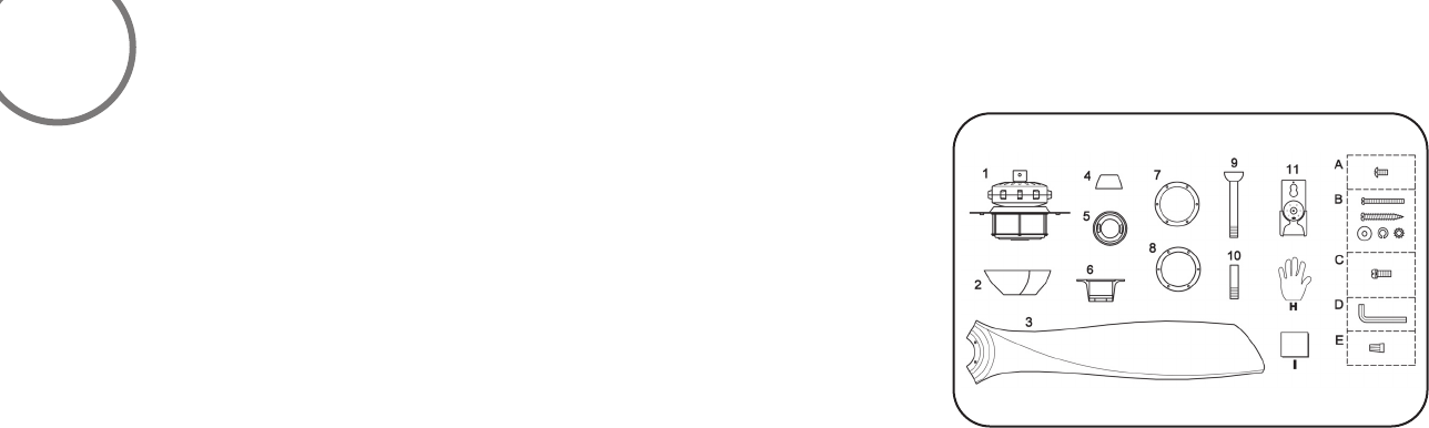
1. Fan motor/housing
ass'y
2. Canopy
3. Fan blade
4. Coupling cover
5. Canopy cover
6. Hanger bracket
7. Bottom cap
9. Standard 6"downrod
assembly
8. Ring
10. Minimun 3-1/2" length
downrod (for close to
ceiling mounting only)
11. Remote control
2
PACKAGE CONTENTS
A. Blade attachment hardware:
#10-24x12mm hex screw
(7pcs)
B. Mounting Hardware:
#8-32x38mm screw(2pcs)
#10x38mm wood screw
(2pcs)
3/16"(Ø5.2x8.4x1.0mm)
spring washer(2pcs)
Ø5x14x1mm flat washer
(2pcs)
5/32"(Ø4.4x9.4x0.5-1.0mm
-10 tooth) wash(2 pcs)
C. #8-32x7mm texture hex
screws (7pcs)
D. M3 L hex wrentch(1pcs)
E. Wire nut(3pcs)
G. Balance kit
H. Glove
I. Clean cloth
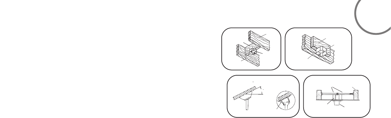
BEGIN INSTALLATION
MOUNTING OPTIONS
If there isn't an existing mounting box,then read the following instructions.Shut the
power off at the circuit breaker or fuse box.
NOTE: THIS CEILING FAN EXCEEDS THE MAXIMUM WEIGHT SPECIFIED BY UL FOR
HANGING FROM A STANDARD OUTLET BOX. SPECIAL REINFORCEMENT OF THE
CEILING IS REQUIRED FOR INSTALLATION.
Secure the ceiling fan's hanging bracket directly from the building structure via the
outlet box.
Figures 1,2 and 3 are examples of different ways to mount the outlet box.
Note:You may need a longer downrod to maintain proper blade clearance when
installing on a steep,sloped ceiling. Longer downrods are available from your Minka-
Aire®dealer.
To hang your fan where there is an existing fixture but no ceiling joist,you may need
to install a hanger bar as shown in Fig. 4 (available at your Minka-Aire®dealer).
Tools Required: Phillips screw driver; slotted screw driver;pliers;wire cutters; electrical tape. 3
CEILING JOIST
CEILING JOIST
OUTLET BOX
CROSS BRACE
PARALLEL WOOD BRACE
(MIN. 2" THICK)
OUTLET
BOX
CEILING JOIST
OR CROSS BRACE
Fig.1 Fig.2
Fig.3 Fig.4
ANGLED CEILING
MAXIMUM 18
ANGLE
PROVIDE STRONG
SUPPORT
HANGER
OPENING
MUST
BE FACING
UP-SIDE
OUTLET BOX
HANGER BAR
(OPTIONAL)
CEILING
JOIST
HANGER
BRACKET
18

REMEMBER to turn off the power. Follow the steps below to hang your
fan properly;
Step 1: Remove the clevis pin and hitch pin from downrod assembly.
(Fig. 5)
Step 2: Carefully feed fan wires, through the downrod and slide the canopy,
canopy cover and coupler up around over the downrod. (Fig. 6)
Step 3: Thread the rod into the motor, coupling and tighten the set screw,
clevis pin and hitch pin. (Fig.7)
Step 4: Secure the hanger bracket to the ceiling outlet box using screws
included with your outlet box and washers included with the fan.(Fig.8)
Step 5: Now lift motor assembly into position and place downrod ball
into hanger bracket. Rotate until the check groove has dropped into the
registration slot and seats firmly. Rod should not rotate if this is done
correctly(Fig.9)
HANGING THE FAN
4
WARNING: All of the parts, hardware and components such as the
hanger bracket and hanger ball have been provided for your safety
and the proper installation of your new ceiling fan. The use of other parts,
hardware or components not supplied by Minka Aire with the fan will
void the Minka Aire Warranty.
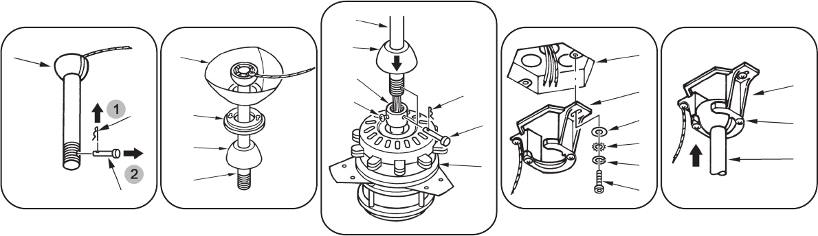
Hanger Ball
Hitch Pin
Clevis Pin
Canopy
Downrod
Downrod
Coupler Cover
Coupler
Set Screw Hitch Pin
Clevis Pin
Blade Holder
Outlet Box
Coupling Cover
Canopy cap
Downrod
Hanger Bracket
Hanger Bracket
Registration Slot
Washer
Washer
Screw
Lock Washer
Fig.5 Fig.6 Fig.8 Fig.9
Fig.7
WARNING:To avoid possible electrical shock be sure electricity is turned off at the main fuse or
breaker box before wiring.
Step 1. Motor to House Supply Wires Electrical Connections: Connect the WHITE wire (Neutral) from the
outlet box to the WHITE wire marked "AC in N" from the motor. Connect the BLACK wire (Hot) from the
outlet box to the BLACK wire marked "AC in L" from the motor. Secure all wire connections with the
plastic wire nuts provided. (Fig. 10)
ELECTRICAL CONNECTIONS
5
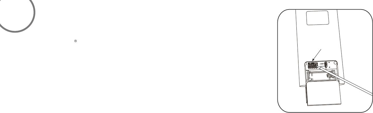
Note: The Aire Control System is equipped with a learning frequency function which has 256 code
combination to prevent potential interference from other remote units. The frequency on your Receiver
and Transmitter units have been preset at the factory. No frequency change is necessary, should you
desire to install another fan within the same home or area with a seperate frequency code please see
the “frequency interference ” trouble shooting section of this instruction manual to learn how to change
the frequency.
Fig.10
YCNEUQERF