Fego Precision Co TR110BL RF Transmiter User Manual 5 Users manual 2
Fego Precision Industrial Co Ltd RF Transmiter 5 Users manual 2
Contents
- 1. 5.Users manual-1
- 2. 5.Users manual-2
5.Users manual-2
Black(hot) Green or bare copper
(ground)
Black ("ac in l")
Ground(green) (connect
toground wire on hanger
bracke if no house ground
wire exists.)
White (neutral)
White ("ac in n")
Fig.11
Step 2. If your outlet box has a GROUND wire (Green or Bare Copper) connect this wire to the Hanger
Ball and Hanger Bracket Ground wires. If your outlet box does not have a Ground Wire, then connect
the Hanger Ball and Hanger Bracket Ground Wires together. Secure wire connection with the plastic
wire nut provided. (Fig. 11)
After all splices are made, check to make sure there are no loose strands. As an additional precaution
we suggest to secure the plastic wire connectors to the wires with electrical tape.
NOTICE: This device complies with Part 15 of FCC rules. Operation is subject to the following two
conditions: (1) This device may not cause harmful interference, and (2) this device must accept any
interference received, including interference that may cause undesired operation.
WARNING: Changes or modifications not expressly approved by the party responsible for compliance
could viod the user’s authority to operate the equipment.
AVIS : Cet appareil est conforme à la section 15 des règlements de la FCC. Opération est sujette aux
deux conditions suivantes: (1) cet appareil ne doit pas émettre de brouillage nuisible, et (2) cet appareil
doit accepter toute interférence reçue, y compris les interférences pouvant entraîner un fonctionnement
indésirable.
AVERTISSEMENT : Les changements ou modifications non expressément approuvés par la partie
responsable de la conformité pourraient viod autorisation de l'utilisateur à faire fonctionner l'équipement.
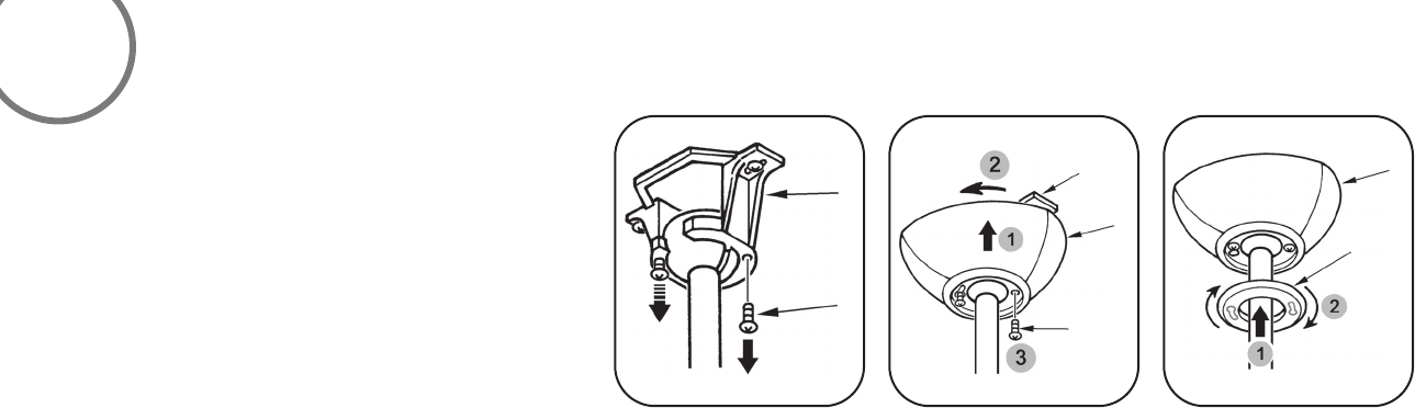
Step 1. Remove 1 of the 2 screws from the bottom of
the hanger bracket and loosen the other one half a turn
from the screw head. (Fig. 12)
Step 2. Slide the canopy up towards the hanger bracket
and place the key hole on the canopy over the screw on
the hanger bracket, turn canopy until it locks in place at
the narrow section of the key holes. (Fig. 13)
Step 3. Align the circular hole on canopy with the remaining
hole on the hanger bracket, secure by tightening the two
set screws. (Fig. 14)
Step 4. Twist the canopy hole cap to fit it on canopy.
FINISHING THE INSTALLATION
Fig.12 Fig.13 Fig.14
6
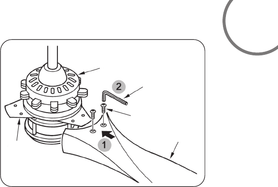
Attach the fan blade to the blade holder on motor using the hex wrench provided in
the screw pack. (Fig. 15)
ATTACHING THE FAN BLADES
Fig.15
Blade Holder
Receiver And Box
Hex Wrentch
Screw
Blade
7
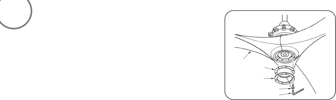
Align the holes on the bottom cap and the holes on the ring to the holes on the blades
and using the hex wrench and hex screws provided secure both to the fan blades. (Fig.16)
ATTACHING THE BOTTOM CAP AND RING
Fig. 16
Blade
Screw
Ring
Hex Wrentch
Bottom Cap
8
9
NOTE: THIS FAN HAS BEEN PRECISION BALANCED AT THE FACTORY AND WILL NOT NEED TO BE BALANCED AGAIN.
cold
3
4
within 3 Minutes of turning the fans
AC power on.
the lowest Speed setting. The fan will continue
to spin until the "STOP" button has been pressed.
The DC motor has a built in
safety against obstruction during operation, if the
fan motor senses a obstruction it will get locked
and will not rotate until the power has been
disconnected for 10 seconds.
The "D" that appears on the back of the remote
control next to the frequency dip switches is used
when using CFL bulbs only. Leaving the dip switch
in the "D" setting will allow for dimming capability.
In the "ON" position it will disable the Dimming
function.
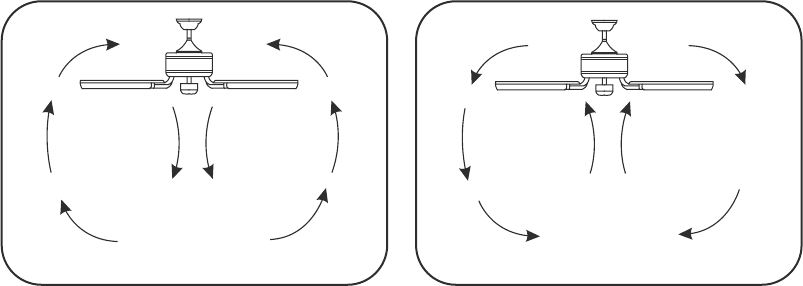
Fig 17 Fig 18
SUMMER OPERATION WINTER OPERATION
Speed settings for warm or cold weather depend
on factors such as room size, ceiling height and
number of fans.
NOTE: To change the direction of the rotation of
the blades the fan must be in operation mode.
Warm Weather (forward)
A DOWNWARD airflow creates a cooling effect
as shown in Figure 17. This allows you to set your
air conditioner on a warmer setting without
affecting your comfort.
Cool Weather (Reverse)
An UPWARD airflow moves warmer air off the
ceiling area as shown in Figure 18.This allows
you to set your heating unit on a cooler setting
without affecting your comfort.

Here are some suggestions to help you maintain your fan.
1. Because of the fan's matural novement,some connections may become
loose. Check the support connections,brackets, and blade attachments
twice a year. Make sure they are secure (It is not necessary to remove
fan from ceiling. )
2. Clean your fan periodically to help maintain its new appearance over
the years. Do not use water when cleaning. This could damage the
motor,or the wood,or possibly cause an electrical shock.
3. Use only a soft brush or lint-free cloth to avoid scratching the finish.
The plating is sealed with a lacquer to minimize discoloration or
tarnishing.
4. You can apply a light coat of furniture polish to the wood for
additional protection and enhanced beauty. Cover small scratches
with a light application of shoe polish.
5. There is no need to oil your fan. The motor has permanently
lubricated bearings.
10
CARE OF YOUR FAN
WARNING
MAKE SURE THE POWER IS OFF AT THE ELECTRICAL PANEL BOX
BEFORE YOU ATTEMPT ANY REPAIRS. REFER TO THE SECTION,
"MAKING ELECTRICAL CONNECTIONS".

SYMPTOM
Fan Wobble
SOLUTION
1.NOTE: All blade sets are grouped by
weight. Because wood and plastic
blades vary in density, the fan may
wobble even though blades are matched.
2.Make sure outlet box is secured to
building structure, if necessary use
the wood screws provided to further
secure outlet box to joist.
3.Make sure hanger bracket is secure to
the outlet box, screws are tight.
SYMPTOM
Fan will not start
SOLUTION
SYMPTOM
Fan sound noisy
SOLUTION
1. Allow a 24-hour "break in" period. Most
noises associated with a new fan will go
away during this time.
2. Make sure all blade attachment screws
are tight.
3. Make sure outlet box is secured to
building structure, if necessary use the
wood screws provided to further secure
outlet box to joist.
4. Make sure hanger bracket is secure to
the outlet box, screws are tight.
TROUBLESHOOTING
11
1.Check to make sure the wall switch is turned on.
2.Check circuit fuses or breakers.
3.Cantion! Make sure the power is turned
off before performing the following steps.
4.Remove canopy and check wire connections.
5.Check wall control transmitter connections
(if applicable).
6.Note: Fan must be installed from a maximum
distance of 40 feet from the transmitting unit
for proper signal transmission between the
transmitting unit and the fan's receiving unit.
SYMPTOM
Frequency interference
SOLUTION
1.Turn the power off to your ceiling fan.
2.Please use a small size tool to change the frequency setting on the control system.
3.Return power to the unit Note: After the AC power is on,do not press any other
button on the transmitter before pressing the “Stop” button, doing so will cause the
procedure to fail.
4.Within 60 seconds of turning the Fan’s AC power ON.Press the transmitter’s Stop”
button for 10 seconds.
5.Once the receiver has detected the set frequency, the down light of your fan if
applicable will blink twice. (there is no indication if your fan is not equipped with
a light).
6.The receiver has now learn the frequency which has been selected on the transmitter.
After completing the steps above, you should be able to operate the ceiling fan and
light. If the fan is not responding to the transmitter, please turn the power off to
the receiver, and repeat the process.
SPECIFICATIONS
12
These are typical readings Your actual fan may vary. They do not Include amps or
wattage used by the light kit.
1151 W.Bradford Court, Corona, CA 92882 For customer assistance call:1-800-307-3267
For any additional information about your
Minka-Aire®Ceiling Fan,please write to:
MKA12120502
Blade Span Fan Speed Volts Amp Watts RPM's CFM N.W. G.W. C.F.
120
120
120
0.07
0.10
0.15
3.17
4.98
8.07
44
60
75
2276
3148
4062
7.1
KGS
8.65 2.76"
KGS
120
120
120t
1
2
3
4
5
6
0.22
0.30
0.42
12.54
17.50
25.92
89
100
115
4957
5899
6604
62"

English Verison