Feig Electronic CPR44 RF Reader Module User Manual ID CPR44
Feig Electronic GmbH RF Reader Module ID CPR44
Contents
- 1. UserManual.pdf
- 2. UserManual_Safety.pdf
- 3. id cpr44 user manual-01
UserManual.pdf
INSTALLATION
final - public (B)
ID CPR44 User Manual.doc
ID CPR44
ISO14443-A and -B RFID Reader

OBID
®
classic-pro Installation ID CPR44
FEIG ELECTRONIC GmbH Page 2 of 16 ID CPR44 User Manual.doc
Note
Copyright 2010 - 2012 by
FEIG ELECTRONIC GmbH
Lange Strasse 4
D-35781 Weilburg
Tel.: +49 6471 3109-0
http://www.feig.de
With the edition of this document, all previous editions become void. Indications made in this manual may be
changed without previous notice.
The reproduction, distribution and utilization of this document as well as the communication of its contents to
others without express authorization is prohibited. Offenders will be held liable for the payment of damages.
All rights reserved in the event of the grant of a patent, utility model or design.
Composition of the information in this document has been done to the best of our knowledge. FEIG
ELECTRONIC GmbH does not guarantee the correctness and completeness of the details given in this
manual and may not be held liable for damages ensuing from incorrect or incomplete information. Since,
despite all our efforts, errors may not be completely avoided, we are always grateful for your useful tips.
The instructions given in this manual are based on advantageous boundary conditions. FEIG ELECTRONIC
GmbH does not give any guarantee promise for perfect function in cross environments and does not give
any guaranty for the functionality of the complete system which incorporates the subject of this document.
FEIG ELECTRONIC call explicit attention that devices which are subject of this document are not designed
with components and testing methods for a level of reliability suitable for use in or in connection with surgical
implants or as critical components in any life support systems whose failure to perform can reasonably be
expected to cause significant injury to a human. To avoid damage, injury, or death, the user or application
designer must take reasonably prudent steps to protect against system failures.
FEIG ELECTRONIC GmbH assumes no responsibility for the use of any information contained in this
document and makes no representation that they free of patent infringement. FEIG ELECTRONIC GmbH
does not convey any license under its patent rights nor the rights of others.
OBID
®
and OBID i-scan
®
is a registered trademark of FEIG ELECTRONIC GmbH.
All brand names, trademarks or logos are property of their respective owners.

OBID
®
classic-pro Installation ID CPR44
FEIG ELECTRONIC GmbH Page 3 of 16 ID CPR44 User Manual.doc
Contents
1. Safety Instructions / Warning - Read before start-up ! 4
2. Characterization ID CPR44.0x-xx 5
3. Installation and wiring 6
3.1. Dimensions ........................................................................................................................ 6
3.2. Connection X1, X2 - Vcc and Interface ............................................................................. 7
3.3. Digital Outputs ................................................................................................................... 8
3.4. SAM Module ....................................................................................................................... 9
3.4.1. Installation of a SAM Card.......................................................................................... 10
3.5. Installation notes ............................................................................................................. 11
3.5.1. Metallic surroundings ................................................................................................. 11
3.5.2. EMC effects on cables ............................................................................................... 11
3.5.3. EMC effects from magnetic fields ............................................................................... 12
4. Radio Approvals 13
4.1. Europe (CE) ...................................................................................................................... 13
4.2. USA (FCC) and Canada (IC) ............................................................................................ 14
5. Technical Data 15

OBID
®
classic-pro Installation ID CPR44
FEIG ELECTRONIC GmbH Page 4 of 16 ID CPR44 User Manual.doc
1. Safety Instructions / Warning - Read before start-up !
• The device may only be used for the intended purpose designed by for the
manufacturer.
• The operation manual should be conveniently kept available at all times for each user.
• Unauthorised changes and the use of spare parts and additional devices which have not
been sold or recommended by the manufacturer may cause fire, electric shocks or
injuries. Such unauthorised measures shall exclude any liability by the manufacturer.
• The liability-prescriptions of the manufacturer in the issue valid at the time of purchase
are valid for the device. The manufacturer shall not be held legally responsible for
inaccuracies, errors, or omissions in the manual or automatically set parameters for a
device or for an incorrect application of a device.
• Repairs may only be executed by the manufacturer.
• Installation, operation, and maintenance procedures should only be carried out by
qualified personnel.
• Use of the device and its installation must be in accordance with national legal
requirements and local electrical codes .
• When working on devices the valid safety regulations must be observed.
• Special advice for carriers of cardiac pacemakers:
Although this device doesn't exceed the valid limits for electromagnetic fields you
should keep a minimum distance of 25 cm between the device and your cardiac pace-
maker and not stay in an immediate proximity of the device respective the antenna for
some time.

OBID
®
classic-pro Installation ID CPR44
FEIG ELECTRONIC GmbH Page 5 of 16 ID CPR44 User Manual.doc
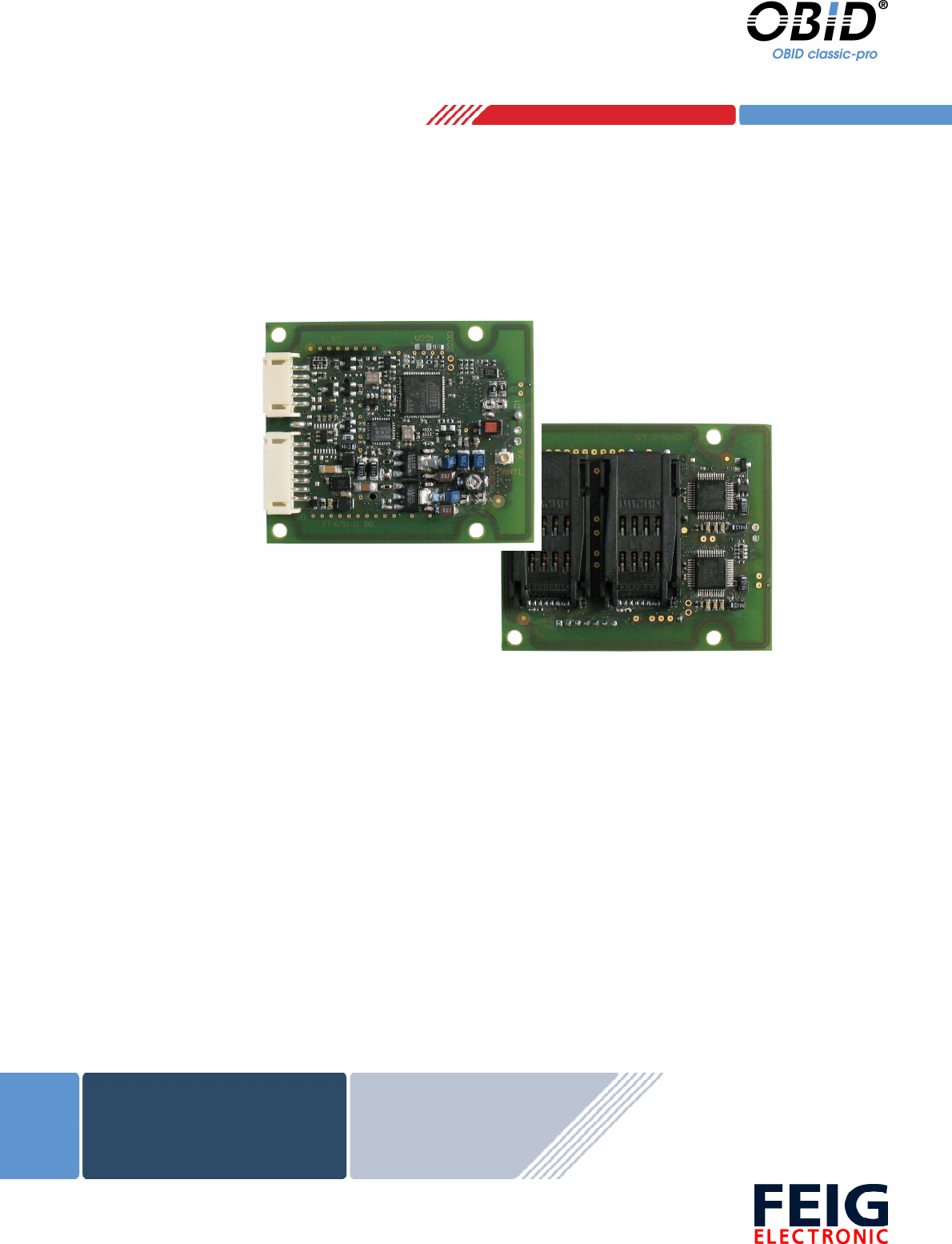
2. Characterization ID CPR44
The reader modules ID CPR44 are designed for data exchange (read and write) with passive tran-
sponder according ISO14443 type A and type B and are capable for communication with NFC de-
vices (ISO18092) and supports the mifare classic security functions. The small dimensions and the
different available interfaces (RS232-TTL or USB) makes it suitable for an easy integration into
terminals, housings and other devices. If the device is connected to an USB host it works as a self-
powered device which requires a separate power supply.
The following different types are available:
CPR44-4SCUSB
CPR44-CUSB
Dimensions L x D x H (mm) 50 x 60 x 13,8 50 x 60 x 7,3
Power supply 5 V / DC
SAM Socket 4 -
Digital outputs 3
Interface
• RS232-TTL
• USB full-speed (12Mbit/s)
ID CPR44-4SCUSB
Reader module with internal antenna. The reader modules ID CPR44-4SCUSB are equipped with
4 sockets for Security Access Modules (SAM) in ID000 format.
ID CPR44-SCUSB
Reader module with internal antenna. The reader modules ID CPR44-SCUSB has no Security Ac-
cess Modules sockets.
Because of their high performance and a wide range of different configuration parameters the
reader modules ID CPR44 is suitable for a lot of applications like access control, ePayment,
eTicketing and public transport..
For further details about configuration parameters and commands please refer to the ID CPR44-
Family manual (H90700-xe-ID-B.pdf).
OBID
®
classic-pro Installation ID CPR44
FEIG ELECTRONIC GmbH Page 6 of 16 ID CPR44 User Manual.doc
X2
X1
1
1
ANT
44
44
50
7,5
24,8
14
18
60
7,2
R1,5
7,4
19,2
J1
X6
3
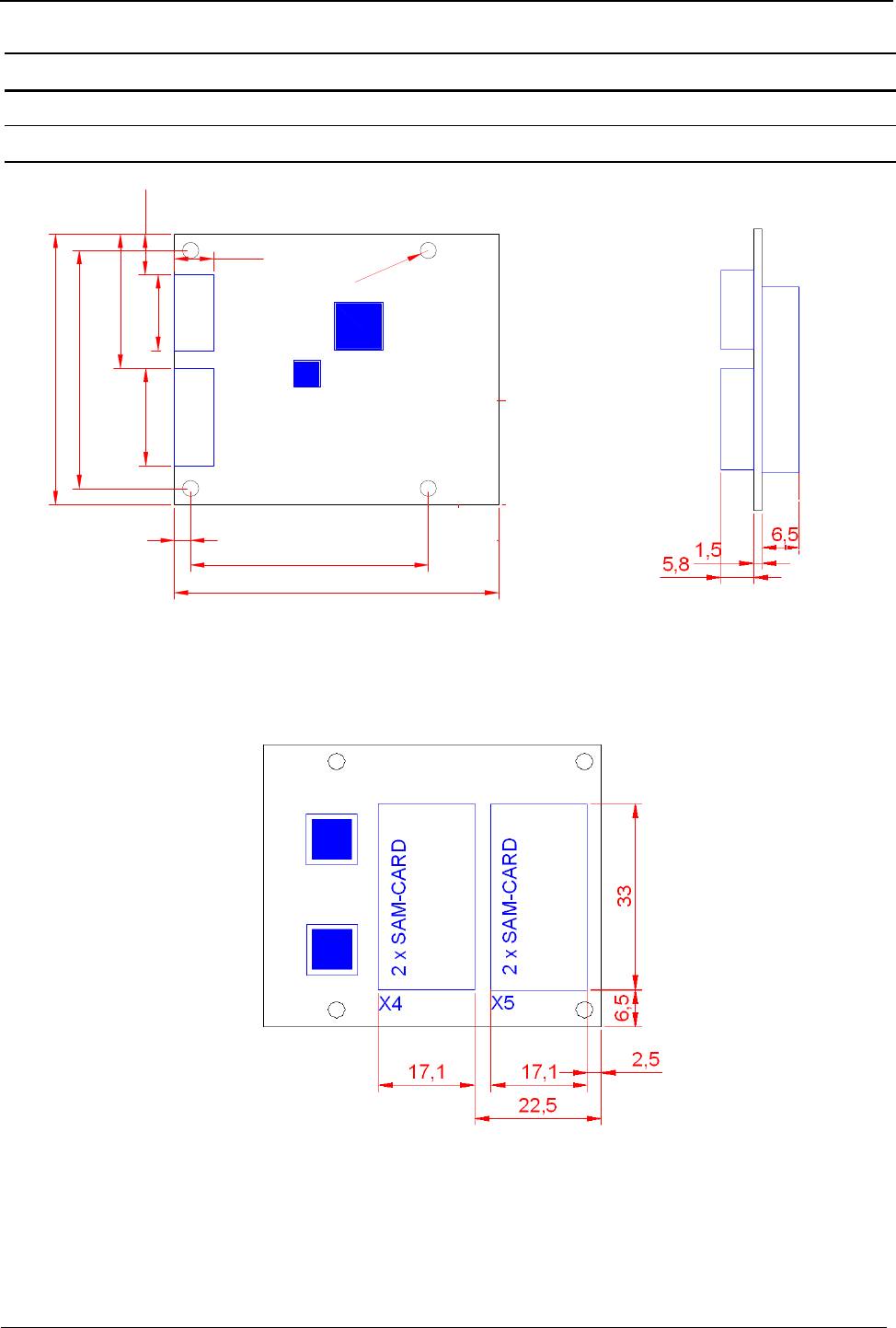
3. Installation and wiring
3.1. Dimensions
Fig. 1 Side view
(* only types with SAM)
Fig. 3 Button view. Types with SAM
Fig. 2 Top view
*
OBID
®
classic-pro Installation ID CPR44
FEIG ELECTRONIC GmbH Page 7 of 16 ID CPR44 User Manual.doc
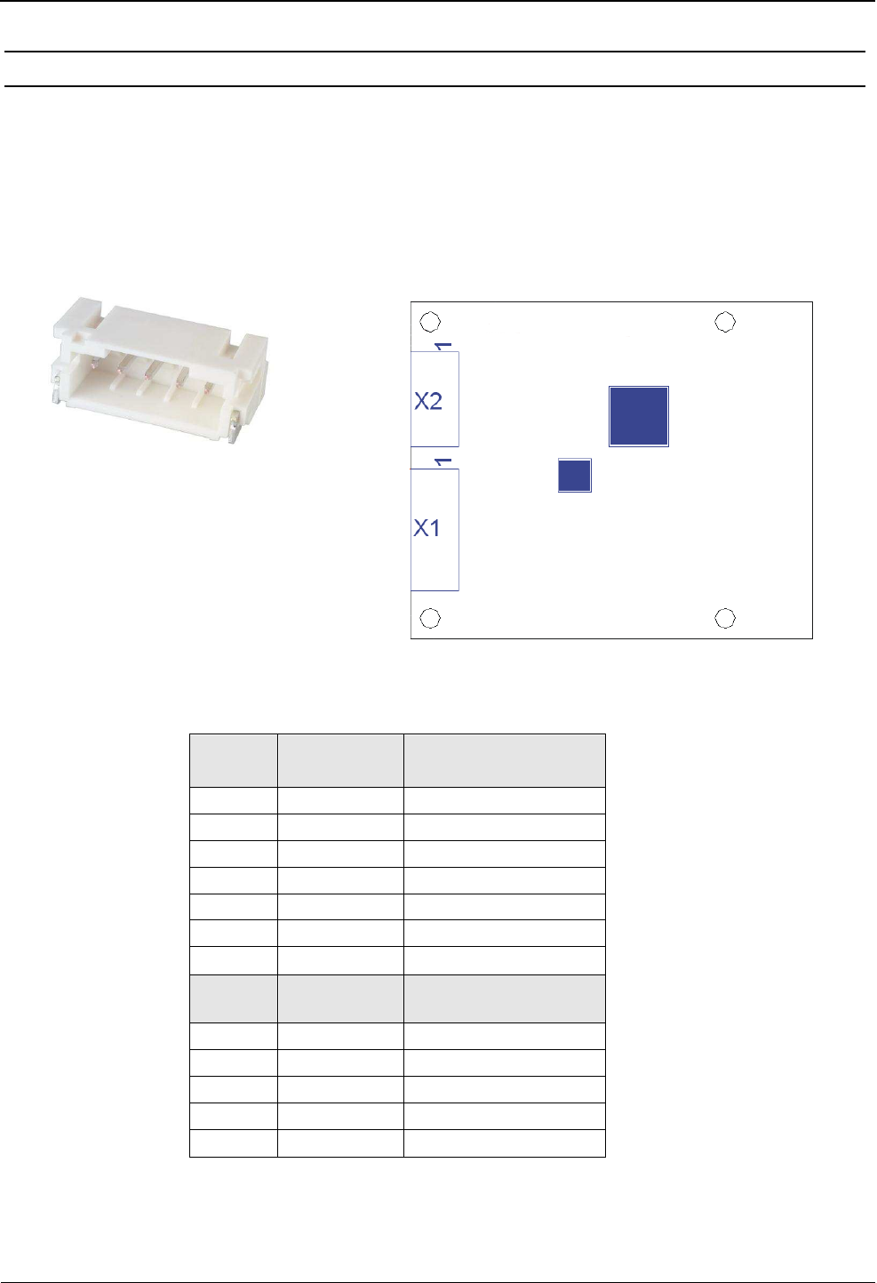
3.2. Connection X1, X2 - Vcc and Interface
The reader can be connected to a RS232-TTL interface and the power supply by using the multi-
pin connector X1. The multi-pin connector X2 provide the connection for the USB interface. The
device is a self-powered USB device which requires a separate power supply.
The following figure 5 and the table shows the assignment of the pins X1 (7pol.) and X2 (5pol.) Typ
“JST PH” RM 2 mm (horizontal).
X1
Pin-No. Symbol ID CPR44
1 OUT1 Digital Output 1
2 OUT2 Digital Output 2
3 OUT3 Digital Output 3
4 GND*
5 RxD RS232-TTL
6 TxD RS232-TTL
7 VCC** + 5 V DC ± 5 %
X2
Pin-No.
1 Shielding USB-Cable Shielding
2 GND*
3 USB-D PLUS
4 USB-D MINUS
5 VCC** + 5 V DC ± 5 %
* GND are connected internal directly
** VCC are connected internal directly. Feed-In VCC only at one pin!
Fig. 5 Plug and connections
Fig. 4 Plug „JST PH“
OBID
®
classic-pro Installation ID CPR44
FEIG ELECTRONIC GmbH Page 8 of 16 ID CPR44 User Manual.doc
NOTICE:
• The reader has to supplied by a limited power supply (e.g. NEC Class 2/LPS power sup-
ply) according IEC EN 60950, only
• Use only regulated power supply’s.
• The connection cable (RS232TTL, USB, VCC) should be as short as possible and must be
shorter than 3 m.
• Reversing the polarity of the supply voltage may destroy the device.
• Supply voltages outside the specifications may destroy the device.
• If switching power supplies are used with the module, be sure that there is adequate fil-
tering.
• Noise from the power supply can result in a reduction of the read/write range of the
module.
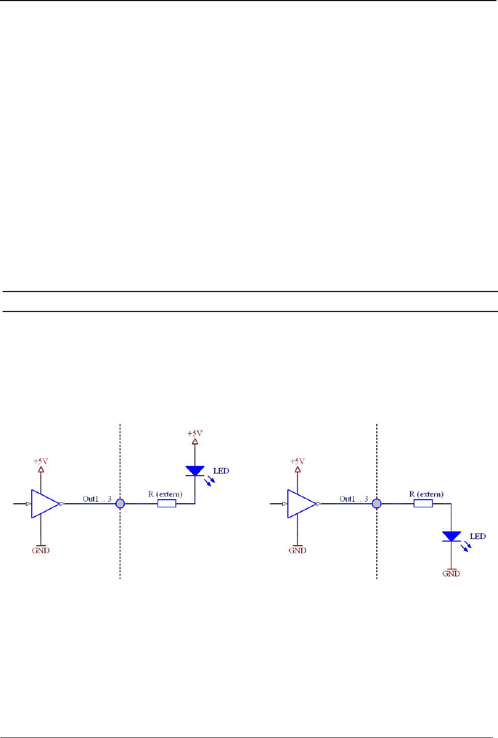
3.3. Digital Outputs
The Fig. 6 shows the circuit diagram of the digital outputs OUT1 – OUT3. The digital outputs are
intended for the connection of external LED’s.
Fig. 6 Wiring of digital outputs OUT1...3
OBID
®
classic-pro Installation ID CPR44
FEIG ELECTRONIC GmbH Page 9 of 16 ID CPR44 User Manual.doc
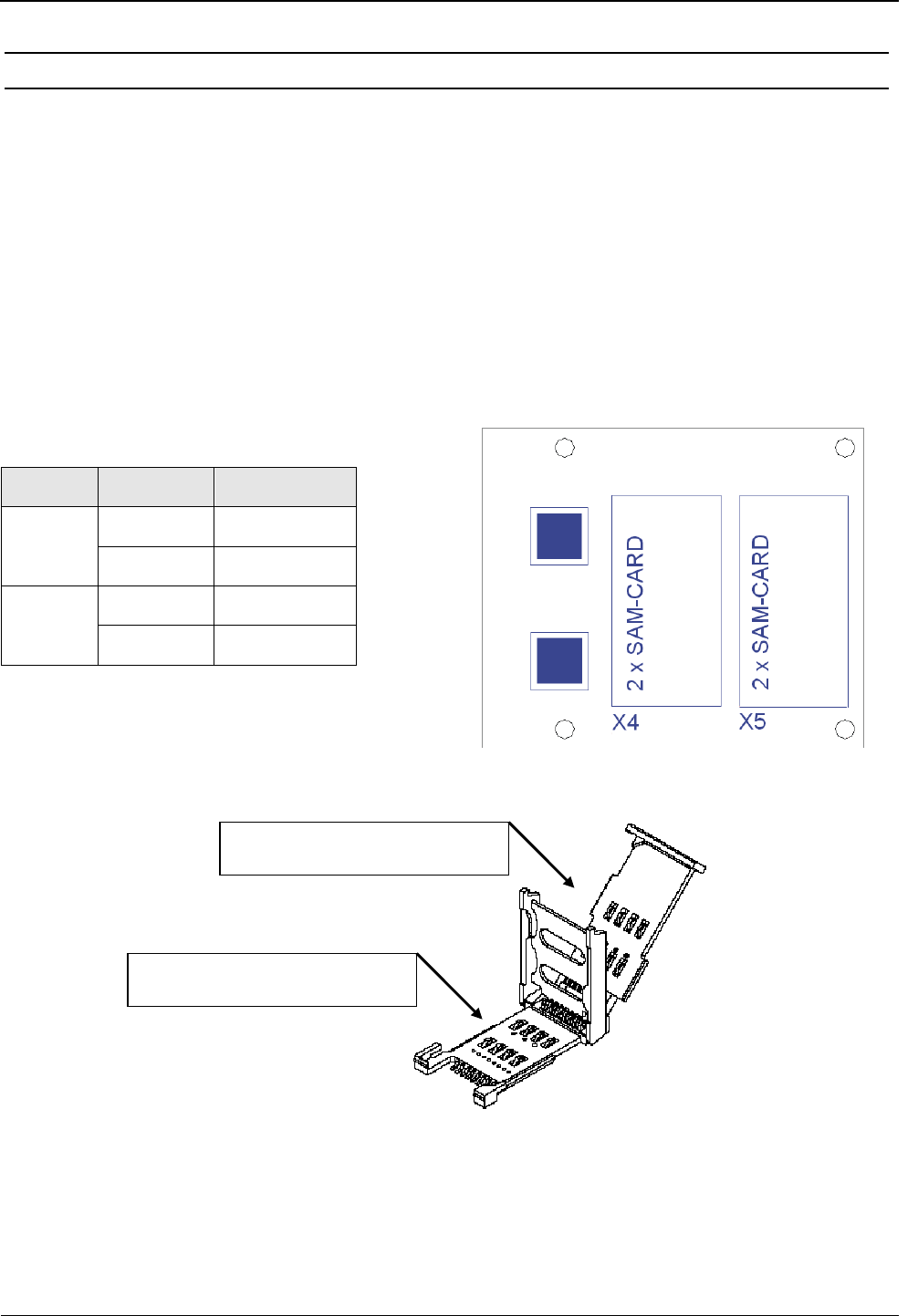
3.4. SAM Module
Fig. 8 shows the position of the 2 SAM connector (double stacked) X4 and X5. Each SAM con-
nector is designed for two ID000 formatted (SIM Karte) SAM modules.
NOTICE
• The SAM connectors are designed only for occasional opening and closing cycles.
• Wrong inserted SAM modules and forcefully opening or closing will damage the SAM
connectors.
Socket Position SAM Number
X4 top 3
button 1
X5 top 4
button 2
Fig. 8 SAM Modul
Slot for SAM Card 3 and 4
Slot for SAM Card 1 and 2
Fig. 7 Position der 4 SAM Module
OBID
®
classic-pro Installation ID CPR44
FEIG ELECTRONIC GmbH Page 10 of 16 ID CPR44 User Manual.doc
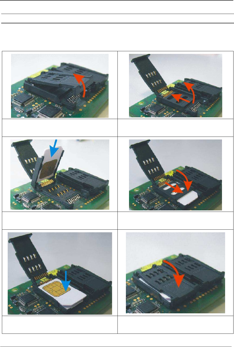
3.4.1. Installation of a SAM Card
The following step by step instruction shows the installation of the SAM Card 1 and 3 into the SAM
connector X4. The installation of the SAM Cards 2 and 4 in the socket X5 must be done in the
same way.
1. Unlatch the top cover at the front edge. 2. Push the cover of lower slot backwards and
open it
3. Put the SAM module 1 into the cover of the
lower slot. The contact plate face down
4. Turn down the cover of the lower slot and
push it forward till the cover is locked.
5. Place the SAM Cart 3 with the contact face at
the top on the cover of the lower slot.
6. Close the top cover with carefully pressure to
snap into place.

OBID
®
classic-pro Installation ID CPR44
FEIG ELECTRONIC GmbH Page 11 of 16 ID CPR44 User Manual.doc
3.5. Installation notes
Be aware of the following possible environmental factors when installing an ID CPR44into another
device :
• Effects from nearby metal objects
⇒ Detuning of the integrated antenna
⇒ Impaired communication of the antenna’s magnetic field
• EMC effects on cables
⇒ Impaired communication between reader and transponder
• EMC effects from magnetic fields
⇒ Impaired communication between reader and transponder
3.5.1. Metallic surroundings
When installing an ID CPR44into another device, be sure that there are no metal surfaces or ob-
jects in the direct vicinity of the reader if possible. These can detune the antenna and thus reduce
the magnetic field of the integrated antenna. This will in turn result in reduced read distances for
the reader.
The distance between the reader and a metal surface should be at least 3 cm. Note that
even other circuit boards may act like metal objects depending on how much copper they
contain.
If a metallic surrounding cannot be avoided, stable function should at least be ensured by keeping
the distance as great as possible.
The area between the antenna and transponder as well as the area on the other side of the tran-
sponder should also be kept clear of metal parts.
Since any change in the metallic environment will result in detuning of the integrated antenna and
therefore to impaired function, no moving metal parts, such as metallic fans, should be allowed in
the vicinity of the reader.
3.5.2. EMC effects on cables
In spite of the internal EMC filters inside the reader, high levels of noise on the supply voltage can
result in impairment of the communication between the reader and transponder.
When installing an ID CPR44 into another device, be sure therefore that a clean, noise-free power
supply is used.

OBID
®
classic-pro Installation ID CPR44
FEIG ELECTRONIC GmbH Page 12 of 16 ID CPR44 User Manual.doc
3.5.3. EMC effects from magnetic fields
The communication principle of RFID- Technology is based on the modulation of electromagnetic
fields. Alternating magnetic fields in the vicinity of the antenna can have a negative influence on
the reader function.
Sources of such magnetic interference fields include coils within a primary or secondary switching
power supply.
When determining the position of the reader and antenna within a device, check the device for any
possible sources of interference as described above. If necessary, use shielding to suppress such
interference.

OBID
®
classic-pro Installation ID CPR44
FEIG ELECTRONIC GmbH Page 13 of 16 ID CPR44 User Manual.doc
4. Radio Approvals
4.1. Europe (CE)
When used according to regulation, this radio equipment conforms with the basic requirements of
Article 3 and the other relevant provisions of the R&TTE Guideline 1999/EC dated March 99.
Equipment Classification according ETSI EN 300 330: Class 2

OBID
®
classic-pro Installation ID CPR44
FEIG ELECTRONIC GmbH Page 14 of 16 ID CPR44 User Manual.doc
4.2. USA (FCC) and Canada (IC)
Product name: ID CPR44
FCC ID:
IC:
PJMCPR44
6633A-CPR44
Notice for USA and
Canada
This device complies with Part 15 of the FCC Rules and with
RSS-210 of Industry Canada.
Operation is subject to the following two conditions.
(1) this device may not cause harmful interference, and
(2) this device must accept any interference received,
including interference that may cause undesired operation.
Unauthorized modifications may void the authority granted under
Federal communications Commission Rules permitting the operation
of this device.
This equipment has been tested and found to comply with the limits for
a Class A digital device, pursuant to Part 15 of the FCC Rules. These
limits are designed to provide reasonable protection against harmful
interference when the equipment is operated in a commercial
environment. This equipment generates, uses, and can radiate radio
frequency energy and, if not installed and used in accordance with the
instruction manual, may cause harmful interference to radio
communications. Operation of this equipment in a residential area is
likely to cause harmful interference in which case the user will be
required to correct the interference at his own expense.
Le présent appareil est conforme aux CNR d'Industrie Canada appli-
cables aux appareils radio exempts de licence. L'exploitation est auto-
risée aux deux conditions suivantes :
(1) l'appareil ne doit pas produire de brouillage, et
(2) l'utilisateur de l'appareil doit accepter tout brouillage radioélectrique
subi, même si le brouillage est susceptible d'en compromettre le fonc-
tionnement.
Warning: Changes or modification made to this equipment not expressly approved by
FEIG ELECTRONIC GmbH may void the FCC authorization to operate this equipment.
Installation with FCC / IC Approval:
FCC-/IC-NOTICE: To comply with FCC Part 15 Rules in the United States / with IC Radio Stand-
ards in Canada, the system must be professionally installed to ensure compliance with the Part 15
certification / IC certification. It is the responsibility of the operator and professional installer to en-
sure that only certified systems are deployed in the United States / Canada.

OBID
®
classic-pro Installation ID CPR44
FEIG ELECTRONIC GmbH Page 15 of 16 ID CPR44 User Manual.doc
5. Technical Data
Weight approx 20 g
Antenna • Internal (48 mm x 58 mm)
Temperature Range Operating
Storage
-25°C to +70°C
-40°C to +85°C
Humidity 0 to 95 % not condensing
Power Supply • 5 V DC ± 5 % Ripple:
0...250 kHz < 10 mVpp
up from 250 kHz < 0,1 mVpp
Current consumption typ. 300 mA
1
RF Interface ISO14443-A & ISO14443-B (Part 4 fully supported)
106, 212, 424, 847 kbit/s
Supported Transponder
(reading and writing)
mifare classic, mifare Ultralight, mifare Ultralight C,
mifare DESfire, mifare PLUS, Smart MX, my-d proxim-
ity, SLE44R35S, SLE55R, Jewel, SLE66CL,
ST19XR34, SRI4K, SRIX4K, SRI512, SR176, RF360,
etc.
NFC Type 1, 2 and Type 4 in card emulation mode
Operating Frequency 13.56 MHz
RF Transmitting Power 400 mW ± 2 dB
Host-Interface • USB Full-Speed (12 Mbit/s)
Self-Powered Device
• RS232-TTL (4.800 to 230.400 Baud)
Digital Output 3 (I
out
high
max.: 5 mA / I
out
low
max.: 8 mA)
Connector
VCC, RS232TTL, Digital Outputs:
USB:
• JST PH 7pin. (X1)
• JST PH 5pin. (X2)
Contact Interface (ISO7816)
(only types with SAM)
4 * SAM Socked for ID000 Format (SIM-Card)
9600 to 375.000 bit/s
T=0 and T=1 Protocol
for 1,8 V; 3 V; 5 V Smartcards
MTBF
500.000
h
1
Current consumption of SAMs excluded

OBID
®
classic-pro Installation ID CPR44
FEIG ELECTRONIC GmbH Page 16 of 16 ID CPR44 User Manual.doc
USB Driver • PC/SC Driver for Windows
• Native OBID
®
USB Driver for Windows
• Windows
®
CE for different platforms on request
Operating Modes Polling-Mode
EEPROM (for Parameter) 1 * 10
6
write cycles
FLASH (for Firmware) (Firmware update in Application possible)
Radio Approval
Europe EN 300 330
USA FCC 47 CFR Part 15
Canada IC RSS-Gen, RSS-210
EMC EN 301 489
Safety and Health EN 60950
EN 50364
Waste and Hazardous Substances WEEE - 2002/96/EC
RoHS - 2002/95/EC