Feig Electronic CPR46 RFID Reader User Manual
Feig Electronic GmbH RFID Reader
user manual

Date: 2012-06-11 Vers. no. 1.12
m. dudde hochfrequenz-technik Rottland 5a D-51429 Bergisch Gladbach/ Germany Tel: +49 2207-96890 Fax +49 2207-968920
Annex no. 5
Functional Description /
User Manual
INSTALLATION
preliminary - confidential
2013-01-14 - M20514-4e-ID-B.doc
ID CPR46.10 - OBID myAXXESS® flatOne
ISO14443-A and -B, NFC Payment Reader

OBID® classic-pro Installation ID CPR46.10
FEIG ELECTRONIC GmbH Page 2 of 19 M20514-4e-ID-B.doc
Note
© Copyright 2012 by
FEIG ELECTRONIC GmbH
Lange Strasse 4
D-35781 Weilburg
Tel.: +49 6471 3109-0
http://www.feig.de
With the edition of this document, all previous editions become void. Indications made in this manual may be
changed without previous notice.
The reproduction, distribution and utilization of this document as well as the communication of its contents to
others without express authorization is prohibited. Offenders will be held liable for the payment of damages.
All rights reserved in the event of the grant of a patent, utility model or design.
Composition of the information in this document has been done to the best of our knowledge. FEIG
ELECTRONIC GmbH does not guarantee the correctness and completeness of the details given in this ma-
nual and may not be held liable for damages ensuing from incorrect or incomplete information. Since, despite
all our efforts, errors may not be completely avoided, we are always grateful for your useful tips.
The instructions given in this manual are based on advantageous boundary conditions. FEIG ELECTRONIC
GmbH does not give any guarantee promise for perfect function in cross environments and does not give
any guaranty for the functionality of the complete system which incorporates the subject of this document.
FEIG ELECTRONIC call explicit attention that devices which are subject of this document are not designed
with components and testing methods for a level of reliability suitable for use in or in connection with surgical
implants or as critical components in any life support systems whose failure to perform can reasonably be
expected to cause significant injury to a human. To avoid damage, injury, or death, the user or application
designer must take reasonably prudent steps to protect against system failures.
FEIG ELECTRONIC GmbH assumes no responsibility for the use of any information contained in this
document and makes no representation that they free of patent infringement. FEIG ELECTRONIC GmbH
does not convey any license under its patent rights nor the rights of others.
OBID® and OBID i-scan® is a registered trademark of FEIG ELECTRONIC GmbH.
All brand names, trademarks or logos are property of their respective owners.
Contact:
Commercial Questions: obid@feig.de
Technical Questions: obid-support@feig.de

OBID® classic-pro Installation ID CPR46.10
FEIG ELECTRONIC GmbH Page 3 of 19 M20514-4e-ID-B.doc
Contents
1. Safety Instructions / Warning - Read before start-up ! 4
2. Characterization ID CPR46.10 5
2.1. Versions / Ordering Information's ...................................................................................... 6
2.2. Delivery Content ................................................................................................................... 6
2.3. Technical Data ...................................................................................................................... 7
2.4. Dimensions ......................................................................................................................... 10
3. Mechanical Installation 11
3.1. Recommended Front Panel Cutout .................................................................................. 12
3.2. Mounting in Metallic and Nonmetallic Front Panels ....................................................... 13
3.3. Recommended Mounting Frame ....................................................................................... 14
4. Wiring and Electrical Connection 15
4.1. Connection X1, X2 .............................................................................................................. 15
4.2. Standby / Wakeup .............................................................................................................. 16
4.3. SAM Socket (ID CPR46.10-4SUSB only) .......................................................................... 17
4.4. LEDs .................................................................................................................................... 18
5. Radio Approvals 19
5.1. Europe (CE) ......................................................................................................................... 19

OBID® classic-pro Installation ID CPR46.10
FEIG ELECTRONIC GmbH Page 4 of 19 M20514-4e-ID-B.doc
1. Safety Instructions / Warning - Read before start-up !
• The device may only be used for the intended purpose designed by for the
manufacturer.
• The operation manual should be conveniently kept available at all times for each user.
• Unauthorised changes and the use of spare parts and additional devices which have not
been sold or recommended by the manufacturer may cause fire, electric shocks or
injuries. Such unauthorised measures shall exclude any liability by the manufacturer.
• The liability-prescriptions of the manufacturer in the issue valid at the time of purchase
are valid for the device. The manufacturer shall not be held legally responsible for
inaccuracies, errors, or omissions in the manual or automatically set parameters for a
device or for an incorrect application of a device.
• Repairs may only be executed by the manufacturer.
• Installation, operation, and maintenance procedures should only be carried out by
qualified personnel.
• Use of the device and its installation must be in accordance with national legal
requirements and local electrical codes .
• When working on devices the valid safety regulations must be observed.
• Special advice for carriers of cardiac pacemakers:
Although this device doesn't exceed the valid limits for electromagnetic fields you
should keep a minimum distance of 25 cm between the device and your cardiac pace-
maker and not stay in an immediate proximity of the device respective the antenna for
some time.
OBID® classic-pro Installation ID CPR46.10
FEIG ELECTRONIC GmbH Page 5 of 19 M20514-4e-ID-B.doc
2. Characterization ID CPR46.10
The OBID® classic-pro ID CPR46.10 is a transparent EMVCo Level 1 approved contactless RFID
card reader for unattended electronic payment-, eTicket- or eMobility- Applications.
The reader is explicitly designed to be nearly flat installed into a metallic front panel from the back
side like vending machines, ticket machines, petrol- or charging stations, etc. If mounted in nonme-
tallic front plates an additional 2 mm steel frame has to be used. The robust and flat housing front
panel ensures a good protection against water, dust and vandalism.
The ID CPR46.10 supports all common contactless credit and debit cards as well as all other
common ISO14443-A and -B based smart cards and can communicate with NFC devices running
in card emulation mode.
The reader offers high security authentication and encryption. Data transfer between the reader
and the host is AES256 encrypted.
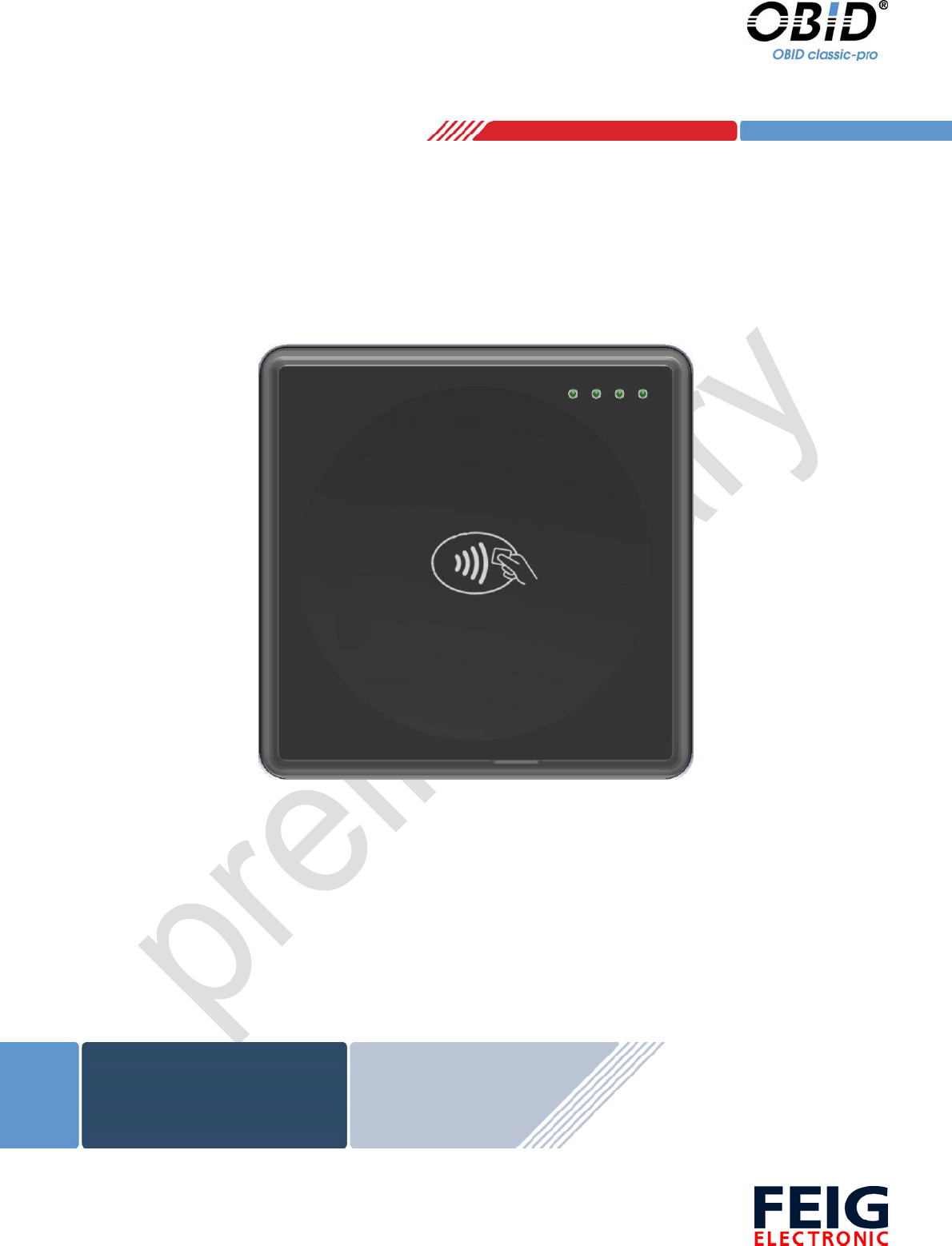
Fig. 1 ID CPR46.10 front view - not installed
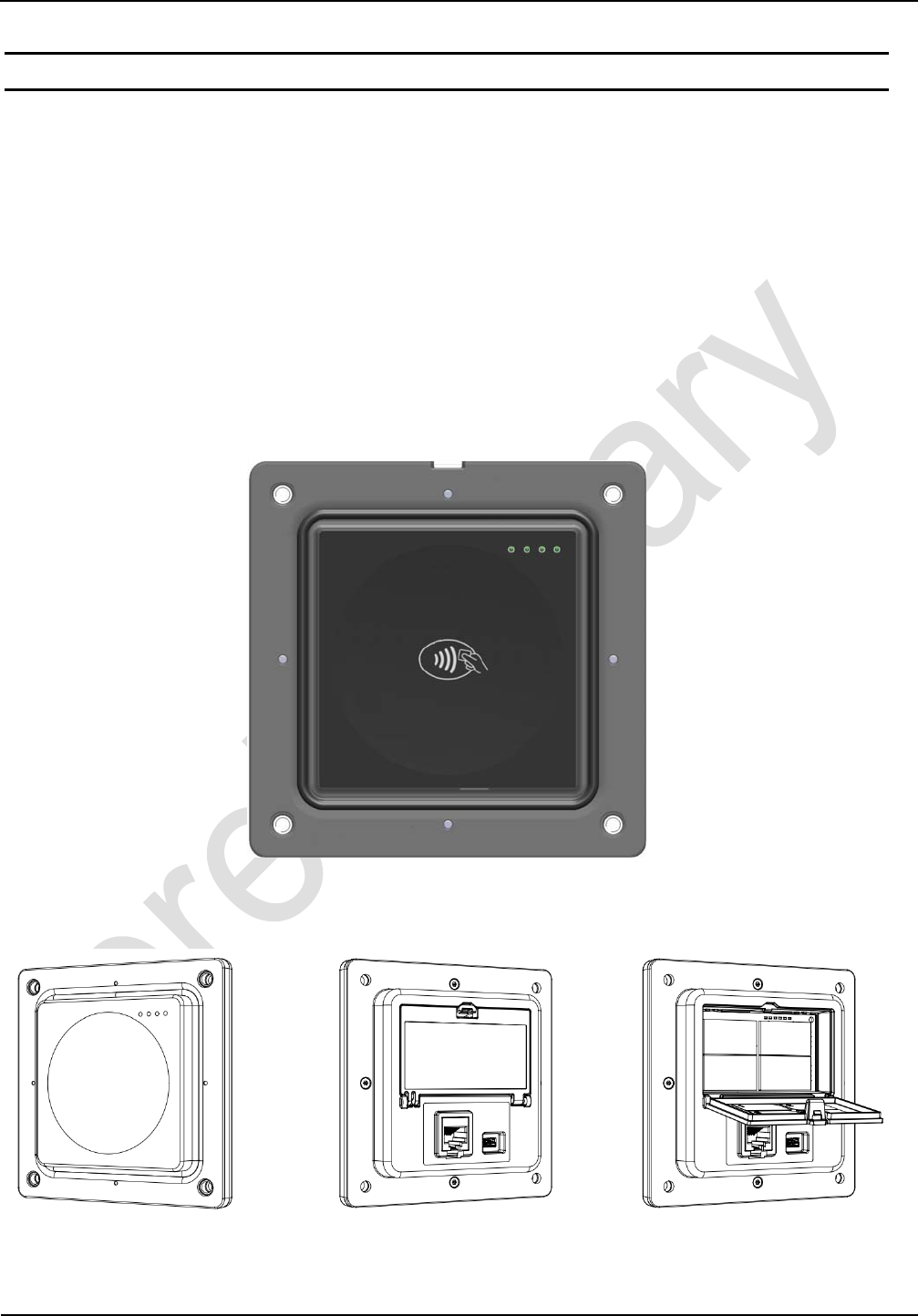
Fig. 2 ID CPR46.10 Front view and rear view with closed and open hatch to SAM sockets

OBID® classic-pro Installation ID CPR46.10
FEIG ELECTRONIC GmbH Page 6 of 19 M20514-4e-ID-B.doc
2.1. Versions / Ordering Information's
The ID CPR46.10 reader family includes one model with four SAM Sockets (ID CPR46.10-4SUSB)
in ID000 format which are accessible via a service hatch in the rear side of the housing and one
model without SAM Sockets (ID CPR46.10-USB). Both models are offering beneath the USB inter-
face a RS232 and a RS232-LVTLL interface.
Model Order No. SAM
Sockets
Host-Interface
USB RS232 RS232
LVTTL
ID CPR46.10-4SUSB
(OBID myAXXESS® flatOne plus) 3889.000.00 4 z z z
ID CPR46.10-USB
(OBID myAXXESS® flatOne) 3889.001.00 - z z z
2.2. Delivery Content
• ID CPR46.10 RFID Reader Unit
• Rubber (EPDM) Sealing Cord (D=4 mm)

OBID® classic-pro Installation ID CPR46.10
FEIG ELECTRONIC GmbH Page 7 of 19 M20514-4e-ID-B.doc
2.3.Technical Data
Housing • transparent front: PC
• rear part: ASA+PC
Dimensions over all (W x H x D)
Visible front section (W x H)
• 120 x 120 x 23,8 mm (4,72 x 4,72, x 0,95 in)
• 85 x 85 mm (3,35 x 3,35 in)
Weight approx 255 g (9 oz)
Protection Class Front Side
Back Side
• IP65 (if accurate installed)
• IP30
Impact protection Class (Front Impact) • IK10 (installed with mounting frame)
Temperature Range Operating
Storage
• -25 °C to +70 °C1 (-13 °F to +158 °F)
• -40 °C to +80 °C (-40 °F to +176 °F)
Humidity 95 % max, (no condensing)
Power Supply (Alternative) • 5 V DC
• 8 to 42 V DC
Antenna internal
Operating Frequency 13,56 MHz
RF Interface ISO/IEC 14443-A / -B
Supported Transponder
(reading and writing)
ISO/IEC 14443-4 compliant smart cards, NFC Type 1, 2
and 4 in card emulation mode, mifare classic, mifare
PLUS, mifare DESFire, mifare ultralight, my-d move,
my-d proximity, Jewel, SR176, SRIx, Calypso (Innova-
tron radio protocol)
Terminal / Host-Interface
• USB Full Speed (12 Mbit/s)
Self-Powered Device
• RS232 (4.800 - 921.600 Baud)
• RS232-LVTTL (4.800 - 921.600 Baud)
Connector
VCC, RS232, RS232TTL, Wakeup:
USB:
• RJ-45 (8P8C) Modular Jack
• Mini USB - B
Operating Modes Polling-Mode (OBID® ISO-Host)
1 With duty cycle
≤
50% and max. active duration of 60 Seconds.

OBID® classic-pro Installation ID CPR46.10
FEIG ELECTRONIC GmbH Page 8 of 19 M20514-4e-ID-B.doc
User Interface
• 4 x LED green
• 1 x LED red
• 1 x LED yellow
• 1 x Buzzer
Contact Interface - ISO7816
(ID CPR46.10-4SUSB only)
4 x independent SAM Sockets for ID000 Format
(SIM-Card)
9600 to 625.000 bit/s
T=0 and T=1 Protocol
support of power class A, B, C
MTBF 150.000 h
CPU / Memory
ARM Cortex-M3 at 120 MHz
Memory 512 kB Flash-ROM, 128 kB RAM
Flash Write Cycles 10.000
Power Consumption – normal Operation
Supply Voltage ID CPR46.10-4SUSB2 ID CPR46.10-USB
5 V DC
8 V DC
12 V DC
36 V DC
42 V DC
2,5 W
3,0 W
3,0 W
3,0 W
3,0 W
2,0 W
2,8 W
2,8 W
2,8 W
2,8 W
Table 1 Max. power consumption
Current Consumption – Stand-by
Supply Voltage Stand-by
5 V DC
8 V DC
12 V DC
24 V DC
36 V DC
280 µA
500 µA
440 µA
300 µA
300 µA
Table 2 Stand-by current in card detection mode
2 Excluding the power consumption of inserted SAM modules.

OBID® classic-pro Installation ID CPR46.10
FEIG ELECTRONIC GmbH Page 9 of 19 M20514-4e-ID-B.doc
2.4. Compliance
Radio Approval
Europe
USA
Canada
EN 300 330
FCC 47 CFR Part 15
IC RSS-Gen, RSS-210
EMC EN 301 489
Safety and Health EN 60950
EN 50364
Waste and Hazardous Substances WEEE - 2002/96/EC
RoHS - 2002/95/EC
EMVCo Conform to Book D - EMV Contactless Communication
Protocol Specification, Version 2.1
OBID® classic-pro Installation ID CPR46.10
FEIG ELECTRONIC GmbH Page 10 of 19 M20514-4e-ID-B.doc
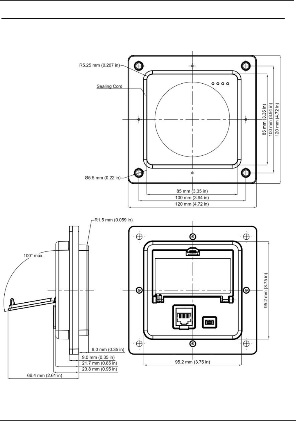
2.5. Dimensions
Fig. 3 ID CPR46.10 dimensions
OBID® classic-pro Installation ID CPR46.10
FEIG ELECTRONIC GmbH Page 11 of 19 M20514-4e-ID-B.doc
3.Mechanical Installation
The ID CPR46.10 is intended to be installed into a front panel from the back side like it is shown in
Fig. 4 ID CPR46.10 installation.
Fig. 4 ID CPR46.10 installation
Recommended torque:
max. 3,5 Nm If mounted with washer and nut.
max. 5,0 Nm If mounted with additional Mounting Frame
(see Fig. 8 Recommended Mounting Frame)
OBID® classic-pro Installation ID CPR46.10
FEIG ELECTRONIC GmbH Page 12 of 19 M20514-4e-ID-B.doc
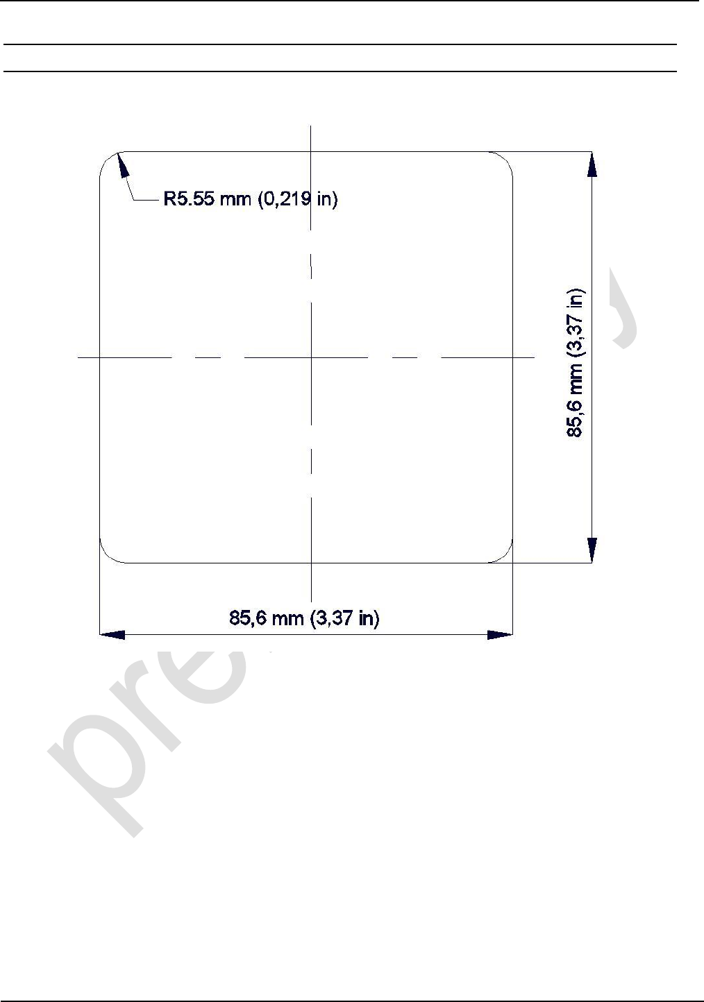
3.1. Recommended Front Panel Cutout
Fig. 5 shows the cutout which is recommend for installation of ID CPR46.10 into a front panel.
Fig. 5 Recommended front panel cutout for ID CPR46.10 installation
OBID® classic-pro Installation ID CPR46.10
FEIG ELECTRONIC GmbH Page 13 of 19 M20514-4e-ID-B.doc
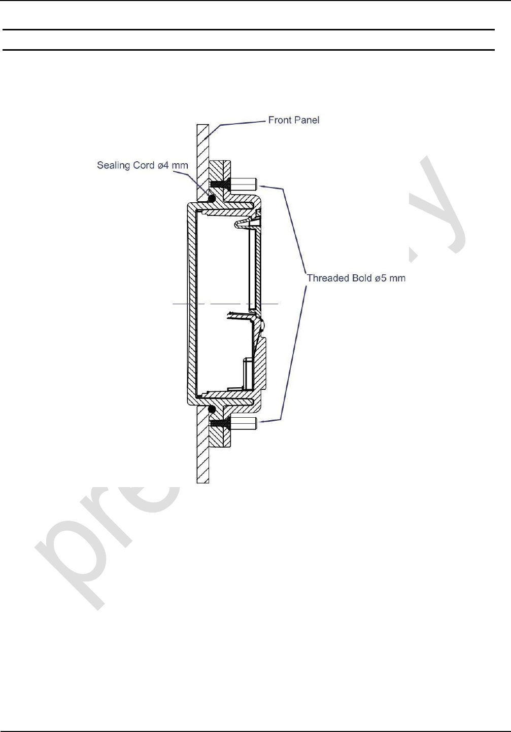
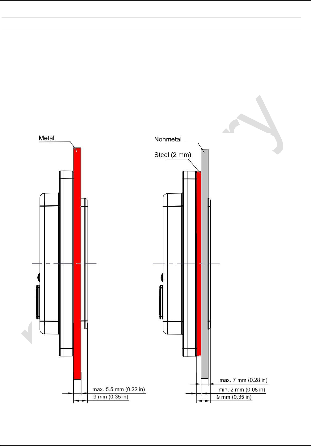
3.2. Mounting in Metallic and Nonmetallic Front Panels
Metallic Front Panels:
The ID CPR46.10 is designed to be mounted into metallic front plates.
The metallic front panel must have a wall thickness between 2,0 and 5,5 mm.
Nonmetallic Front Panels
In cases where ID CPR46.10 shall be used in a nonmetallic front plate like plastic or glass
a 2 mm steel plate has to mounted between ID CPR46.10 and the non metallic front plate.
A sealing between the steel plate and the nonmetallic front plate is recommended to en-
sure the impermeability.
Fig. 6 ID CPR46.10 installation in metallic and non metallic front panels.
OBID® classic-pro Installation ID CPR46.10
FEIG ELECTRONIC GmbH Page 14 of 19 M20514-4e-ID-B.doc
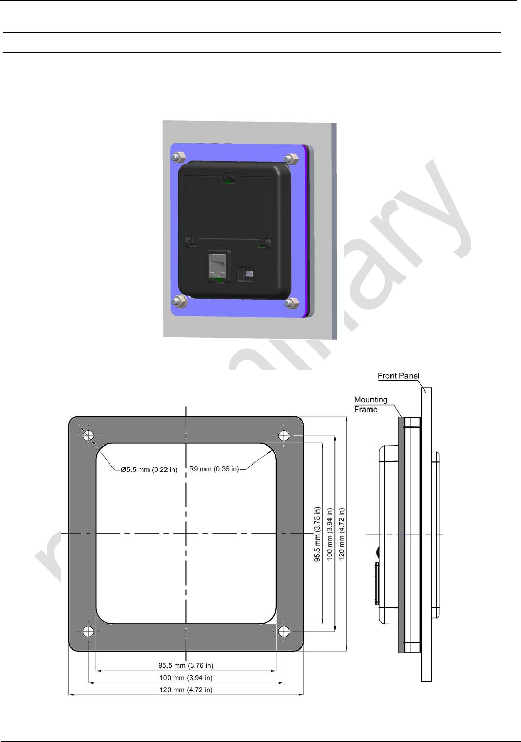
3.3. Recommended Mounting Frame
In order to achieve a good mechanical resistance against external mechanical influences like van-
dalism a additional mounting frame is recommended to be placed behind the mounting flange of
the ID CPR46.10 as shown in Fig. 8.
Fig. 7 Recommended mounting with mounting frame
Fig. 8 Recommended Mounting Frame - Dimensions
OBID® classic-pro Installation ID CPR46.10
FEIG ELECTRONIC GmbH Page 15 of 19 M20514-4e-ID-B.doc
4. Wiring and Electrical Connection
4.1. Connection X1, X2
The ID CPR46.10 offers 2 alternative power supply options. Either "Vin" which can be between 8 V
DC and 42 V DC or Vcc which can be 5 V DC only.
Fig. 9 Plugs for Power Supply, Wakeup and Interfaces
X2 (USB Mini B):
The USB mini connector is for connecting to an USB host. The device is a self-powered
USB device which requires a separate power supply via the RJ-45 connector X1.
NOTICE:
• The reader has to supplied by a limited power supply (e.g. NEC Class 2/LPS power
supply) according IEC EN 60950, only!
• Do never supply the reader with both supply Voltages Vin and Vcc at the same time!
• Supply voltages outside the specifications may destroy the device!
• Use only regulated power supply’s with adequate filtering. Noisy power supplies can
cause malfunctions.
• The host interfaces (RS232 or RS232-LVTTL or USB) can be used exclusive only (not si-
multaneous).
X1
RJ-45 Symbol Function
1 TXD-LVTLL RS232-LVTTL
2 RXD-LVTLL RS232-LVTTL
3 I/O Wakeup
4 Vin 8 V to 42 V DC
5 GND
6 Vcc + 5 V DC ± 2 %
7 TxD RS232
8 RxD RS232
X1 X2
1 8
OBID® classic-pro Installation ID CPR46.10
FEIG ELECTRONIC GmbH Page 16 of 19 M20514-4e-ID-B.doc
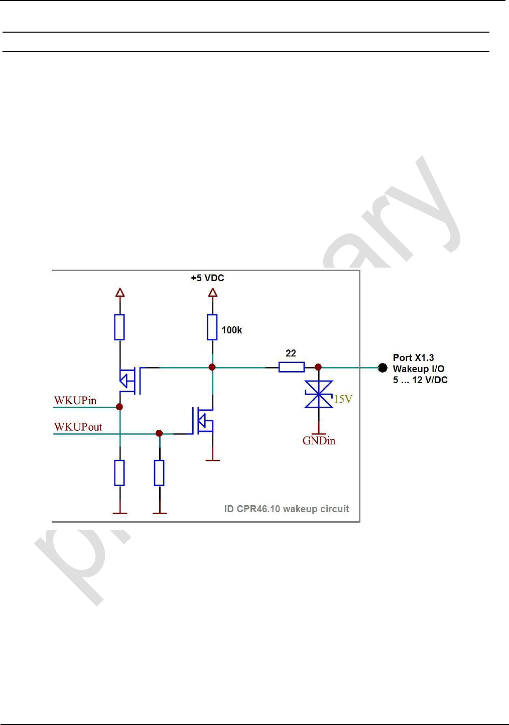
4.2. Standby / Wakeup
The ID CPR46.10 offers a standby mode which can be configured via software commands. If
standby is activated the bidirectional Wakeup I/O on X1, Pin 3 is used for signaling a wakeup event
by the reader. The Wakeup I/O can be used also by the host activate the ID CPR46.10.
To leave the standby mode the reader offers 2 options:
1. Card Detection:
If a RFID transponder card comes in the proximity of the reader the reader awake and pulls
down the Wakeup line on X1, Pin 3.
After the host has recognized this signal he can start reader polling via the host interface.
2. Wakeup Signal by Host:
The host controller can awake the ID CPR46.10 by pulling down the Wakeup line on X1, Pin 3.
Fig. 10 ID CPR46.10 - internal wakeup line circuit
NOTICE:
• If the standby - wakeup option is used in connection with the USB interface the USB
connection will be interrupted while standby mode.
OBID® classic-pro Installation ID CPR46.10
FEIG ELECTRONIC GmbH Page 17 of 19 M20514-4e-ID-B.doc
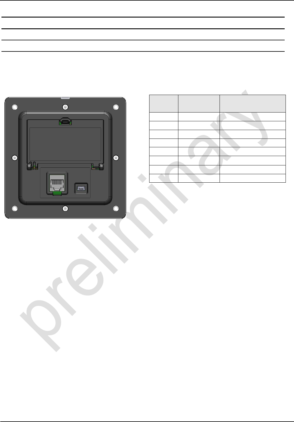
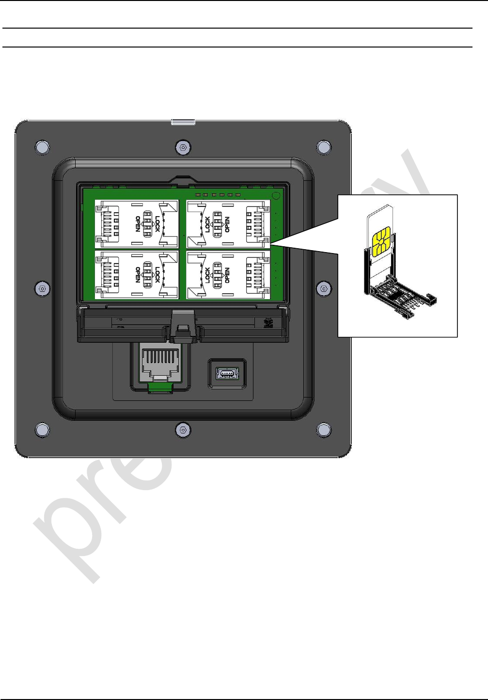
4.3. SAM Socket (ID CPR46.10-4SUSB only)
The ID CPR46.10-4SUSB is equipped with 4 SAM sockets which are located behind the latch on
the backside of the device.
Fig. 11 ID CPR46.10-4SUSB - SAM socket location and handling
n o
p q
OBID® classic-pro Installation ID CPR46.10
FEIG ELECTRONIC GmbH Page 18 of 19 M20514-4e-ID-B.doc
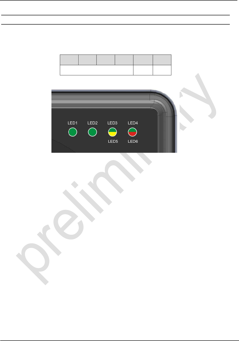
4.4. LEDs
The ID CPR46.10 is equipped with 6 different colored LED (see Fig. 12 ID CPR46.10 - LED posi-
tion and numbering) which can be controlled by the host separately.
LED1 LED2 LED3 LED4 LED5 LED6
green yellow red
Fig. 12 ID CPR46.10 - LED position and numbering

OBID® classic-pro Installation ID CPR46.10
FEIG ELECTRONIC GmbH Page 19 of 19 M20514-4e-ID-B.doc
5. Radio Approvals
5.1. Europe (CE)
When used according to regulation, this radio equipment conforms with the basic requirements of
Article 3 and the other relevant provisions of the R&TTE Guideline 1999/EC dated March 99.
Equipment Classification according ETSI EN 300 330: Class 2
5.2. USA (FCC) / Canada (IC)
FCC ID PJMCPR46
This device complies with Part 15 of the FCC Rules. Operation is subject to the following two
conditions:
(1) this device may not cause harmful interference, and
(2) this device must accept any interference received, including interference that may cause un-
desired operation.
Any changes or modifications not expressly approved by the party responsible for compliance
could void the user's authority to operate the equipment.
NOTE: This equipment has been tested and found to comply with the limits for a Class B digital
device, pursuant to Part 15 of the FCC Rules. These limits are designed to provide reasonable
protection against harmful interference in a residential installation. This equipment generates,
uses and can radiate radio frequency energy and, if not installed and used in accordance with the
instructions, may cause harmful interference to radio communications. However, there is no
guarantee that interference will not occur in a particular installation. If this equipment does cause
harmful interference to radio or television reception,
which can be determined by turning the equipment off and on, the user is encouraged to try to
correct the interference by one or more of the following measures:
• Reorient or relocate the receiving antenna.
• Increase the separation between the equipment and receiver.
• Connect the equipment into an outlet on a circuit different from that to which the receiver is
connected.
• Consult the dealer or an experienced radio/TV technician for help