Feig Electronic LRM2000-2 RFID System User Manual M90401 1e ID B
Feig Electronic GmbH RFID System M90401 1e ID B
UserManual.wiki
>
Feig Electronic
>
LRM2000 2 User Manual
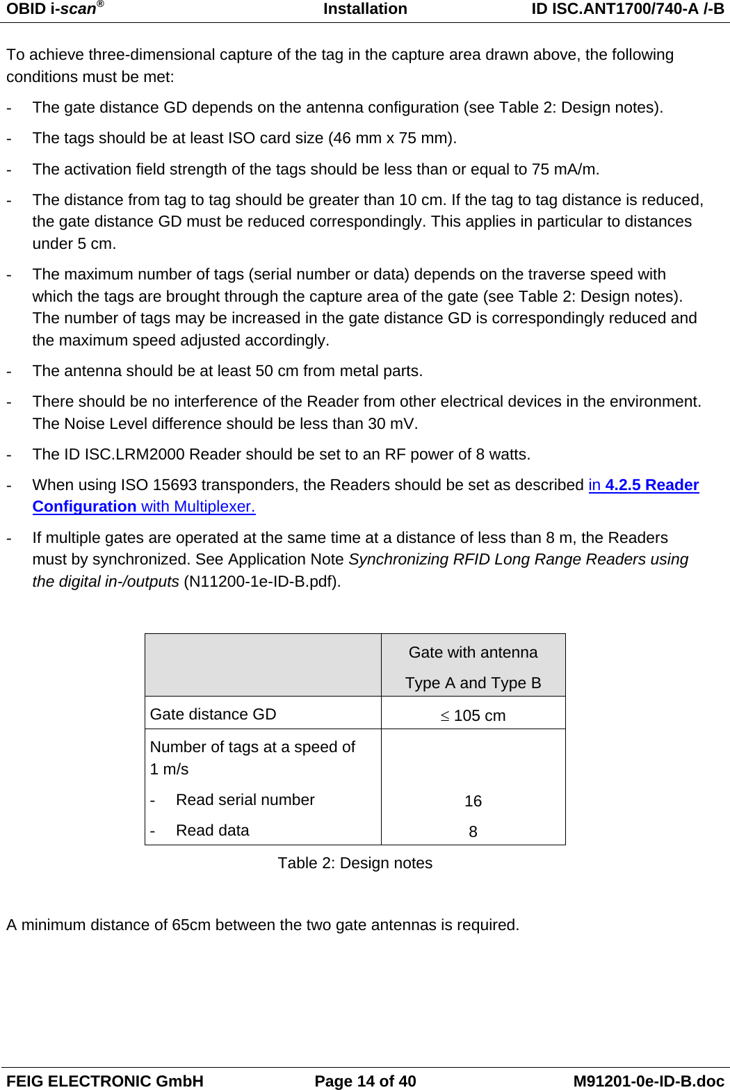
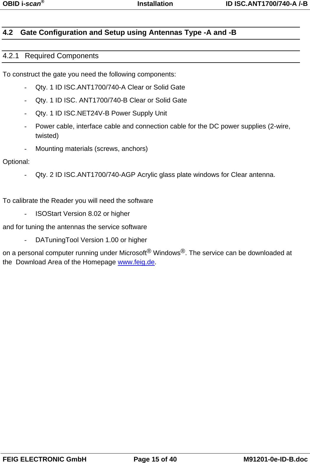
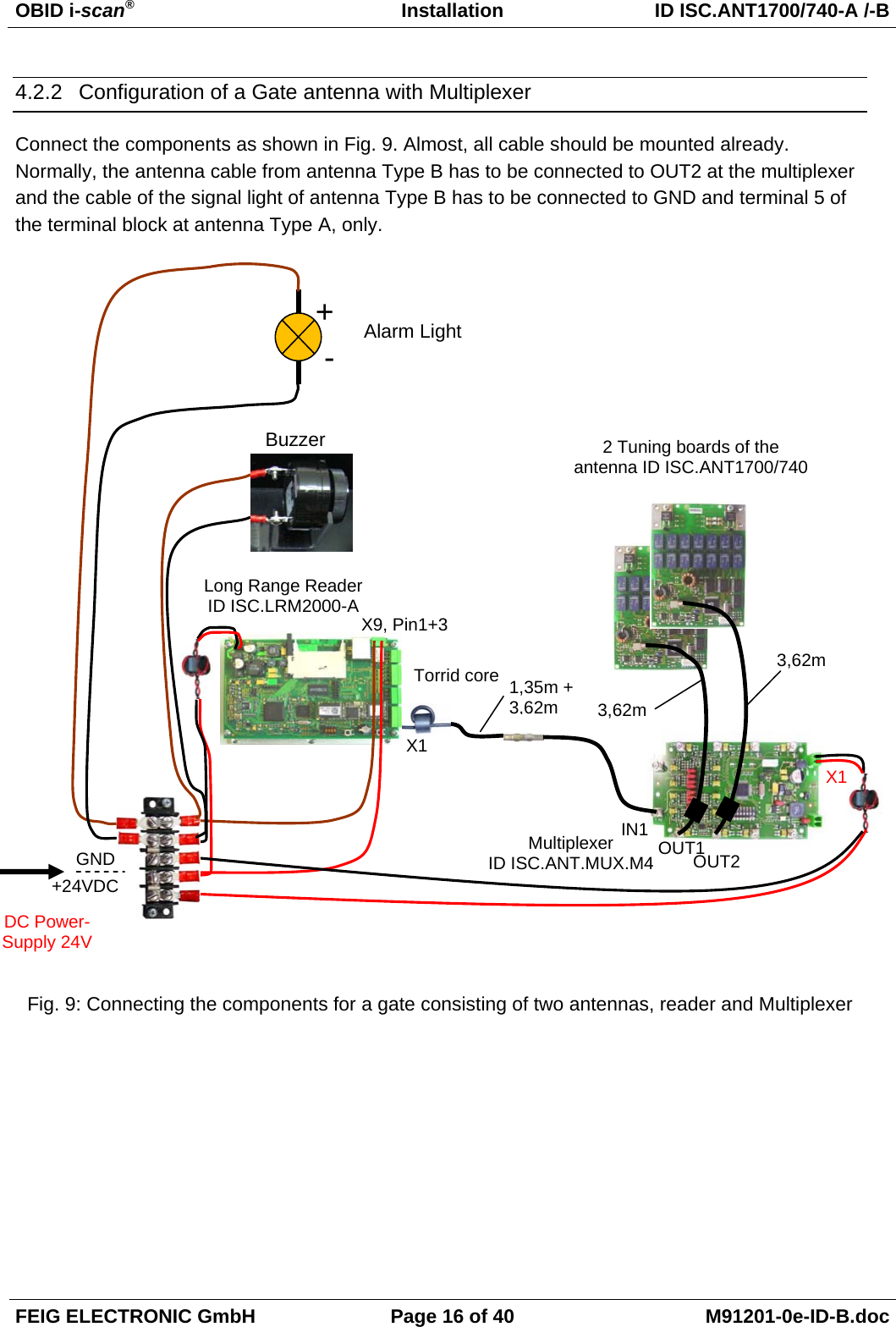
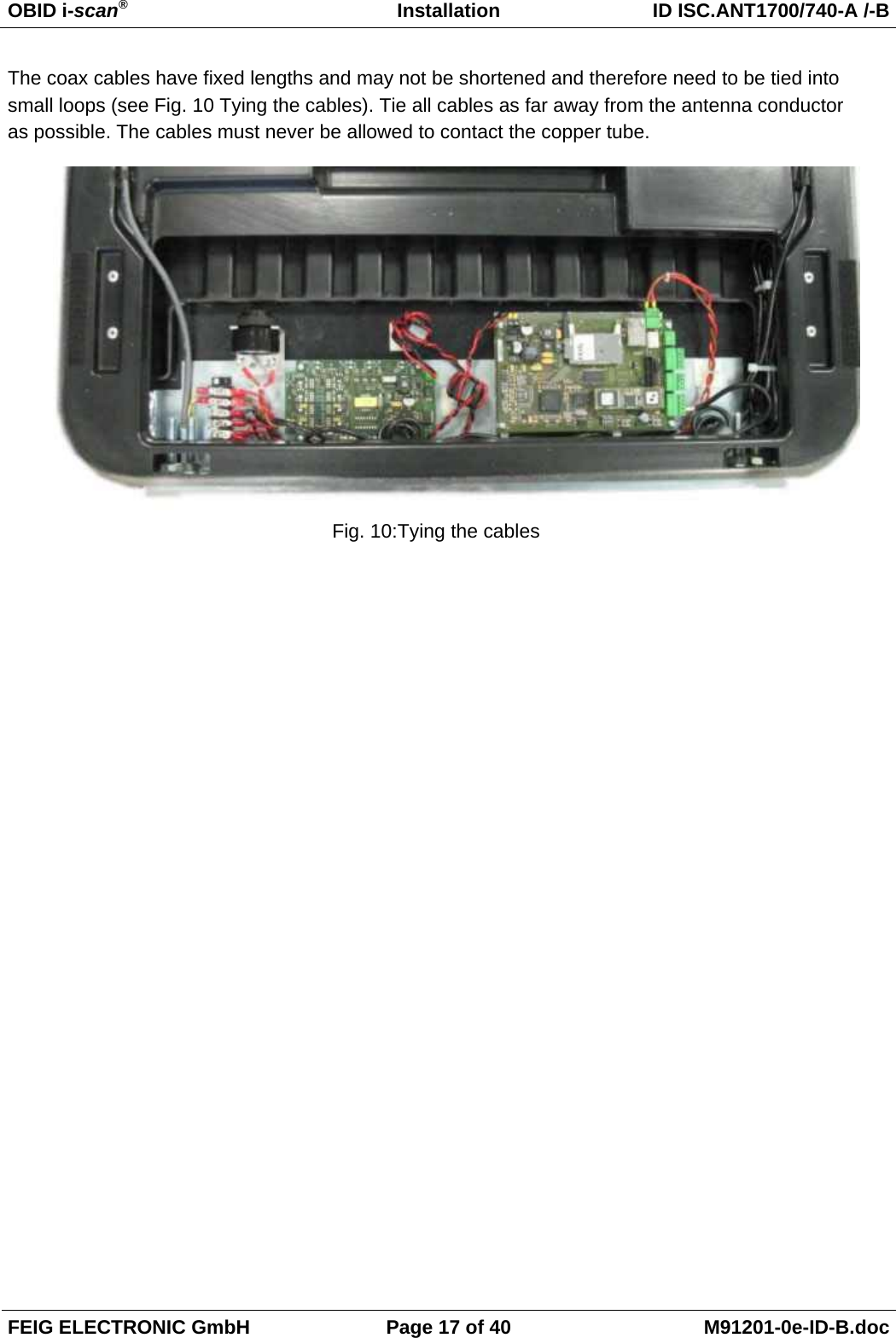
Installation Manual
Navigation menu
Upload a User Manual
Namespaces
Wiki Guide
HTML
PDF
Info
Views
User Manual
Discussion / Help
Navigation
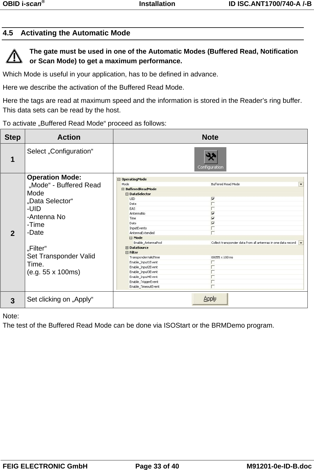
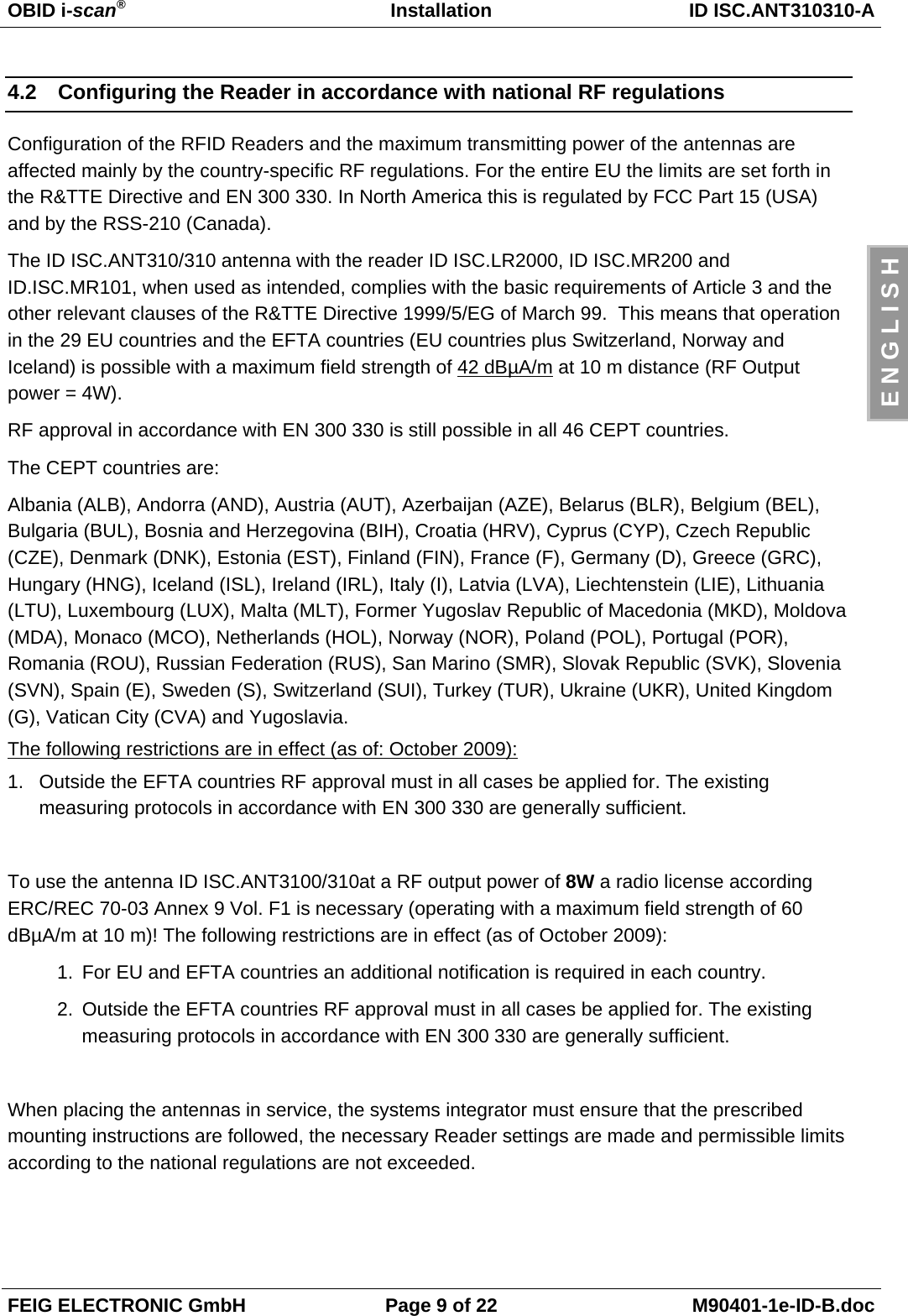
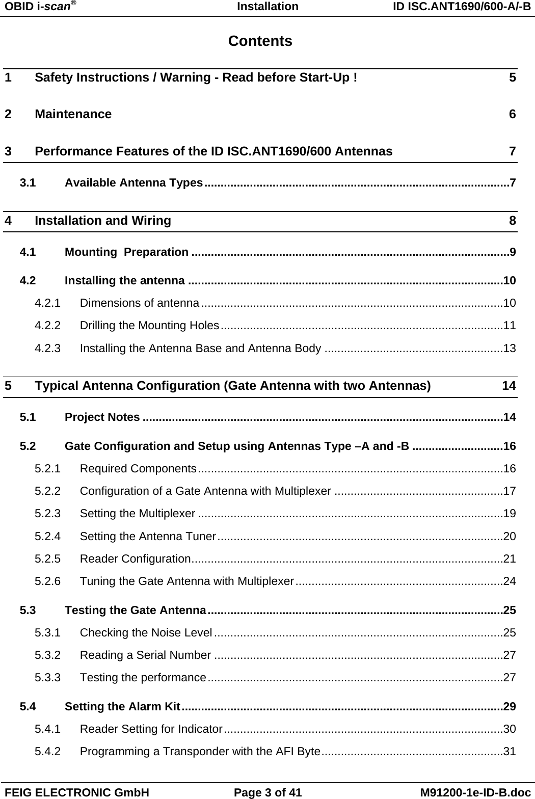
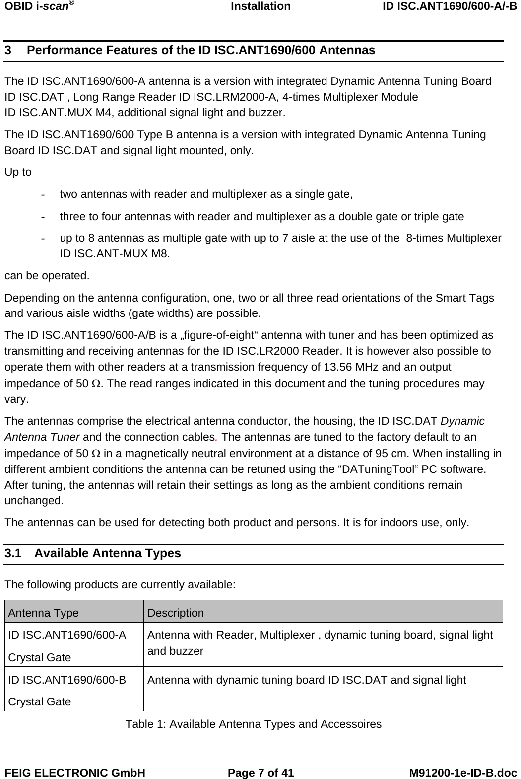
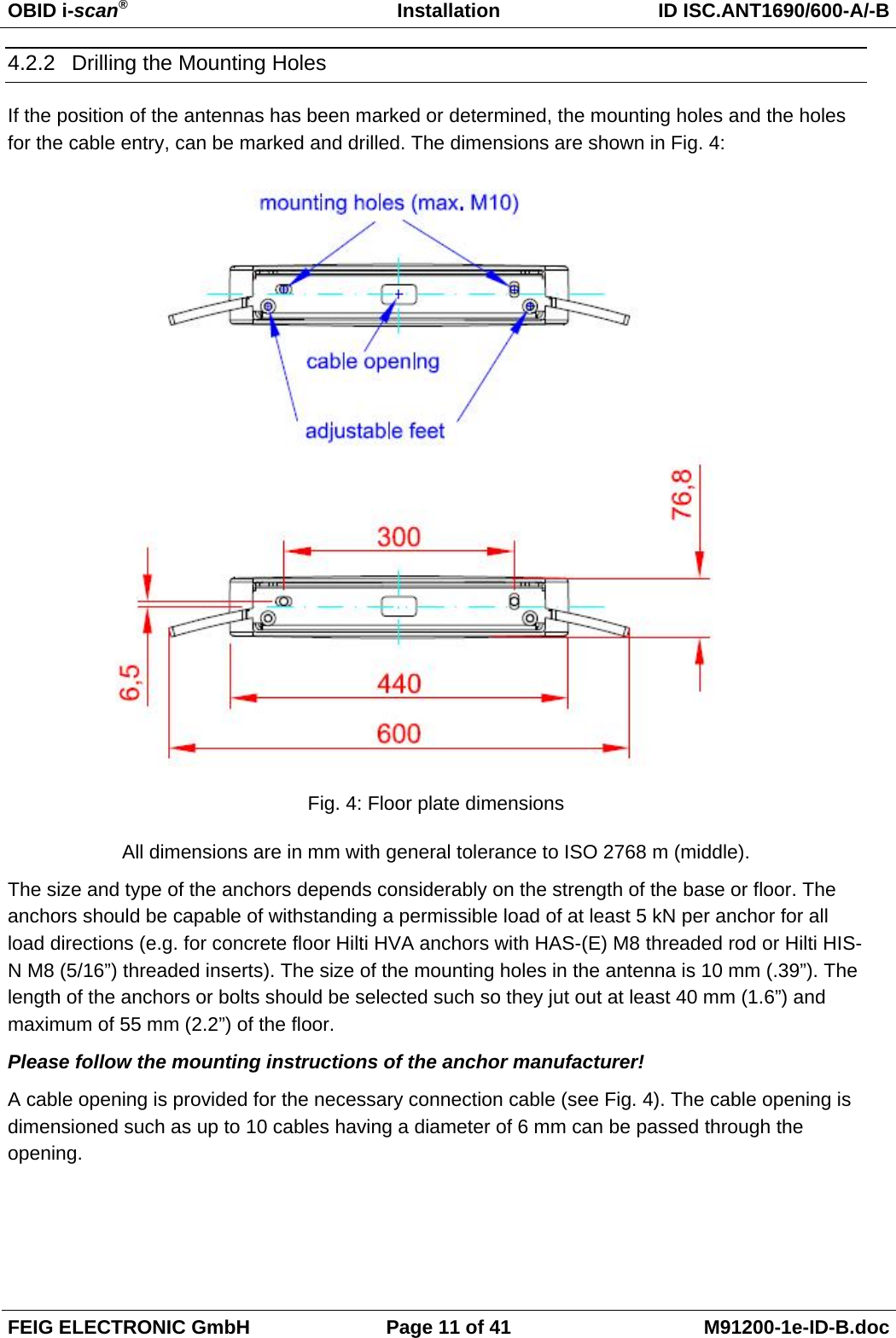
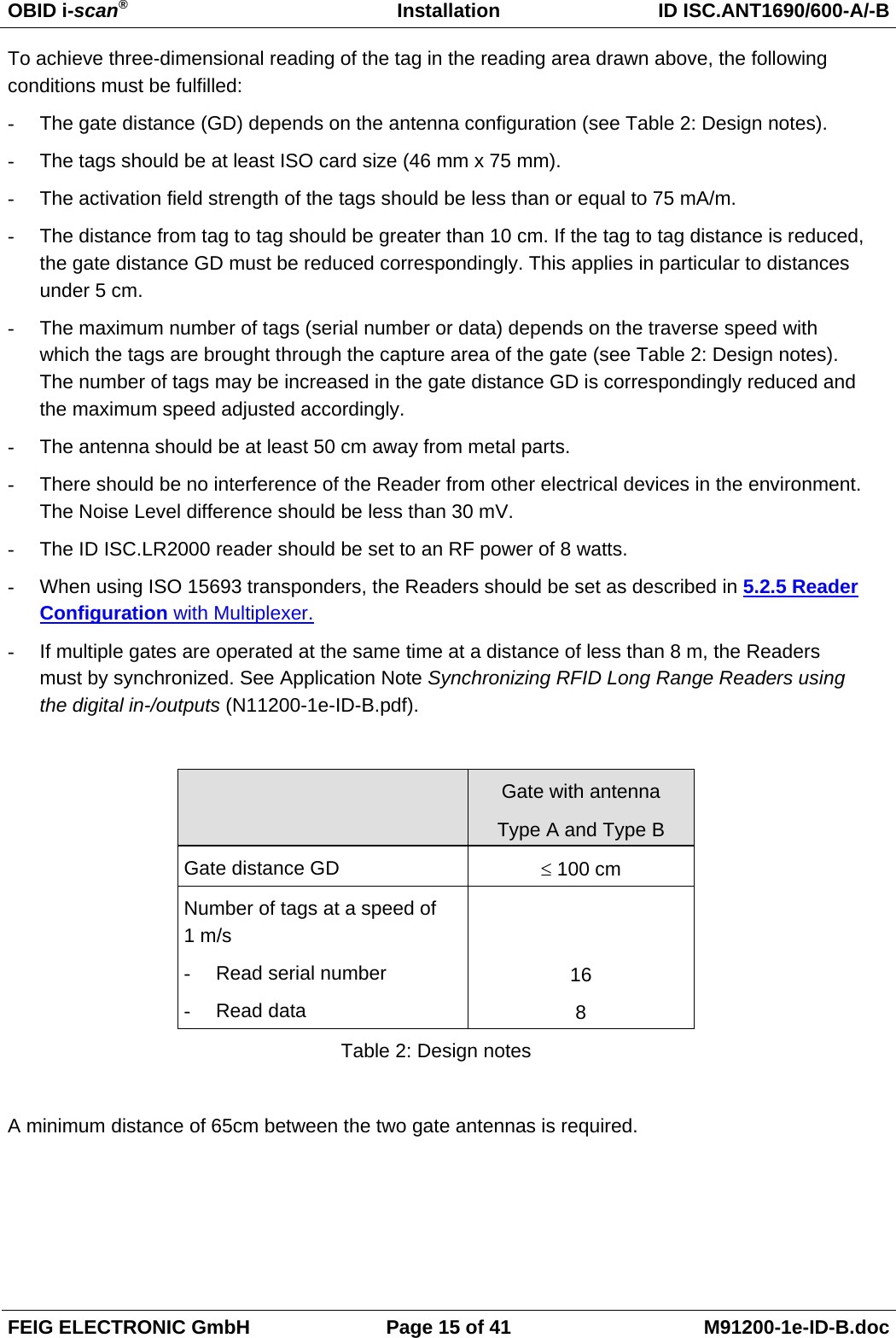
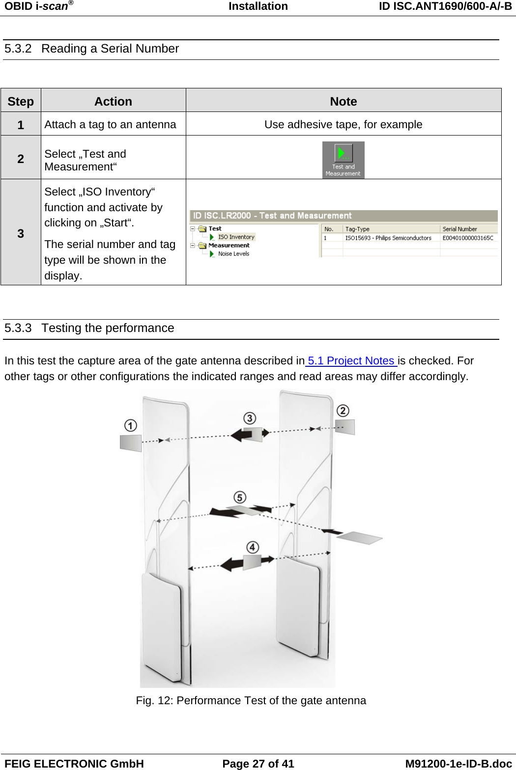
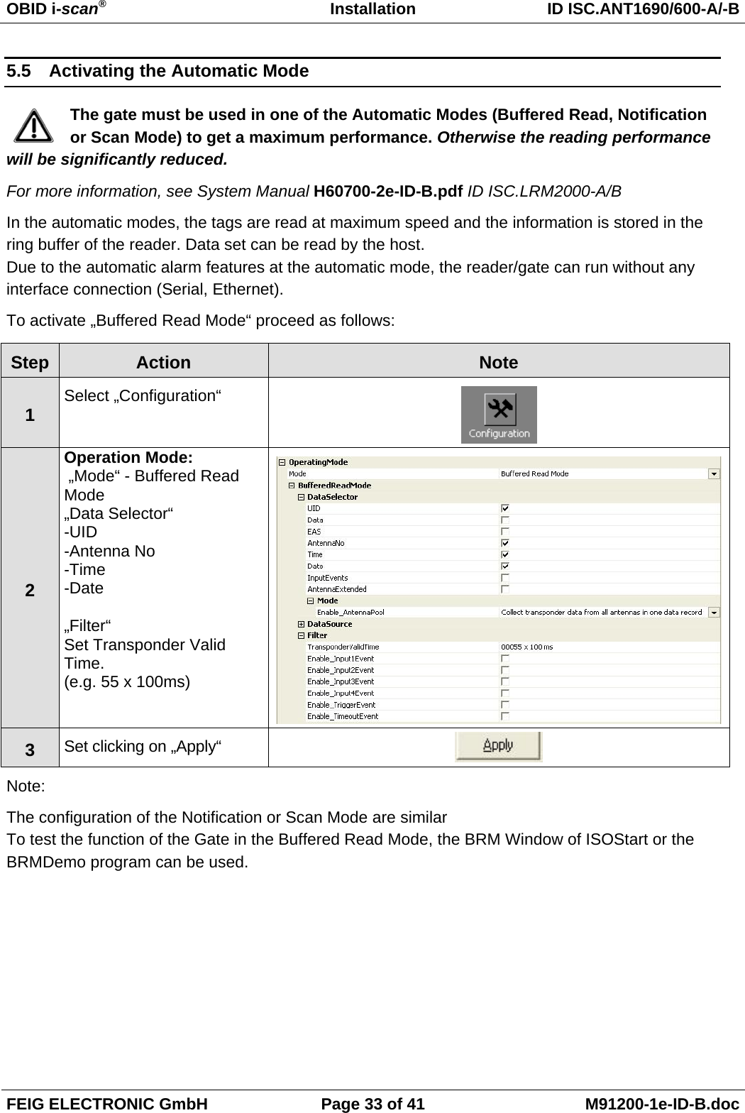
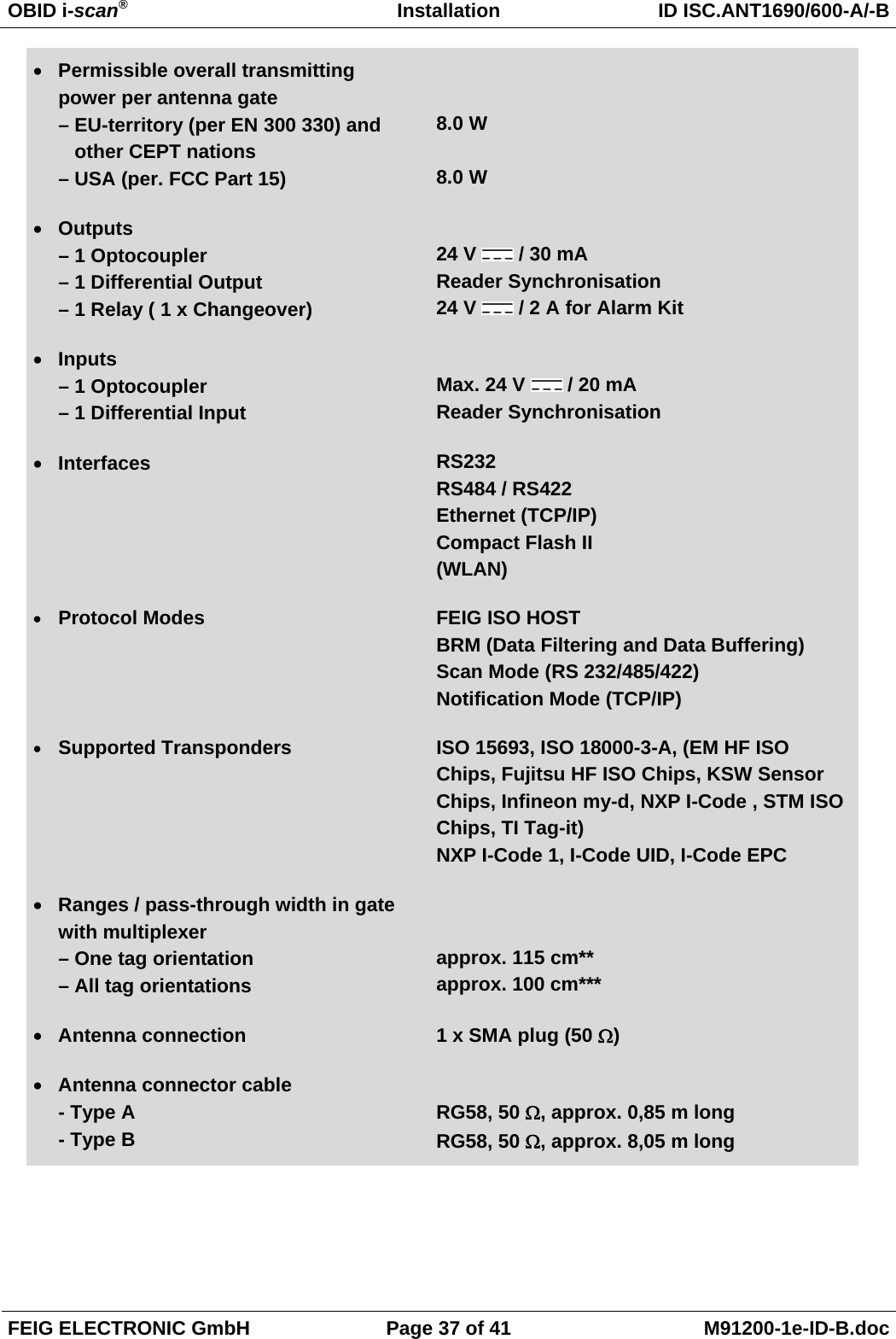
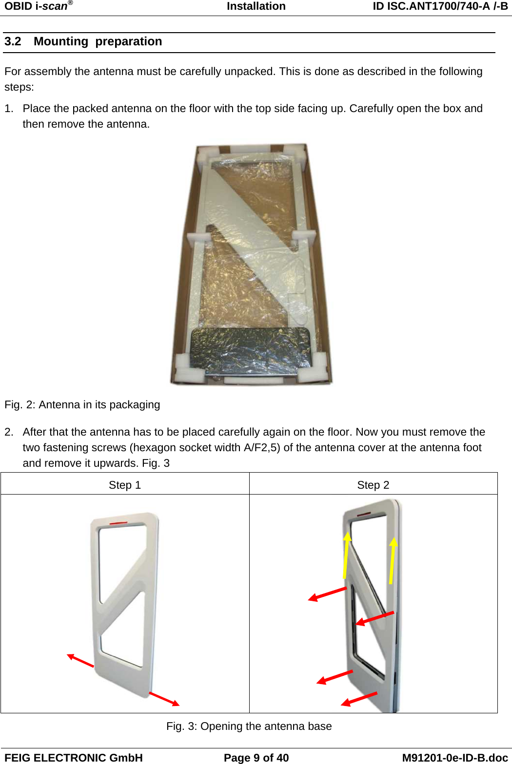
![OBID i-scan® Installation ID ISC.ANT310/310-A FEIG ELECTRONIC GmbH Page 8 of 22 M90401-1e-ID-B.doc Please also observe the following recommendations: • Up to a distance of 50 cm, the antenna cable should always be lead away from the antenna vertically and installed permanently. • In order to obtain an optimum reading range, the antenna connection cable should not be shortened or extended. If an extension is absolutely necessary, please use a 50 Ω cable with a length of 2λ (half the wavelength at 13,56 MHz, RG58=7,20 m). However, this may lead to a minor sensitivity reduction (approx. 2 cm reading range / extension). • Please keep a minimum distance of 30 cm between the antenna cable and all parallel, power cables. After the installation has been completed, an operational check can be performed with the help of the reader and a smart label. With a transmitting power of 4W and a label size of 75 mm x 46 mm (ISO-card size) the reading range in the centre of the antenna should be approx. 50 cm – 60 cm. Otherwise, the following points should be reviewed: • Is the antenna installed near metal? • What is the difference between Umax-Umin of the Noise Level? The difference of the Noise Level should be less than 20 mV (see ISO Start, Test & Measurement). • Is the matching of the antenna of the impedance to the impedance of 50 Ω okay? • Can be checked with the help of an SWR – Meter. See Chapter 4.6 How to measure the voltage standing wave ratio (VSWR). • Do the reader signal a “RF-Warning”? See reader command “[0x6E] Reader Diagnostic” • The distance from tag to tag should be greater than 8 cm. If the tag to tag distance is reduced, losses at the read range can be expected. This applies in particular to distances under 5 cm. • If multiple gates are operated at the same time at a distance of less than 8 m, the Readers must by synchronized. Otherwise, losses at the read range can be expected See Application Note: “Synchronizing RFID Long Range Readers using the Reader Synchroni-zation Interface” (N11200-3e-ID-B.pdf).](https://usermanual.wiki/Feig-Electronic/LRM2000-2/User-Guide-1292029-Page-8.png)
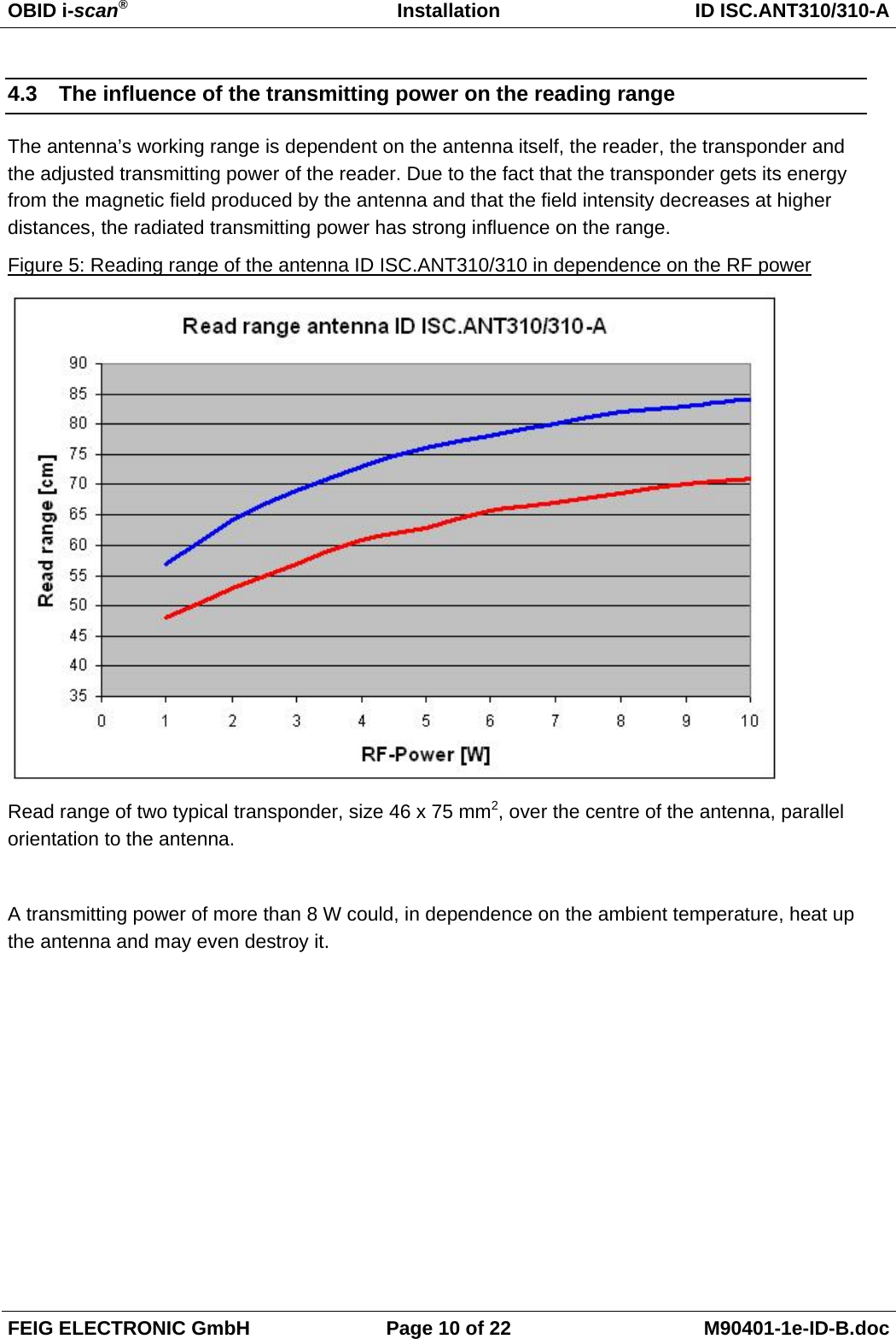
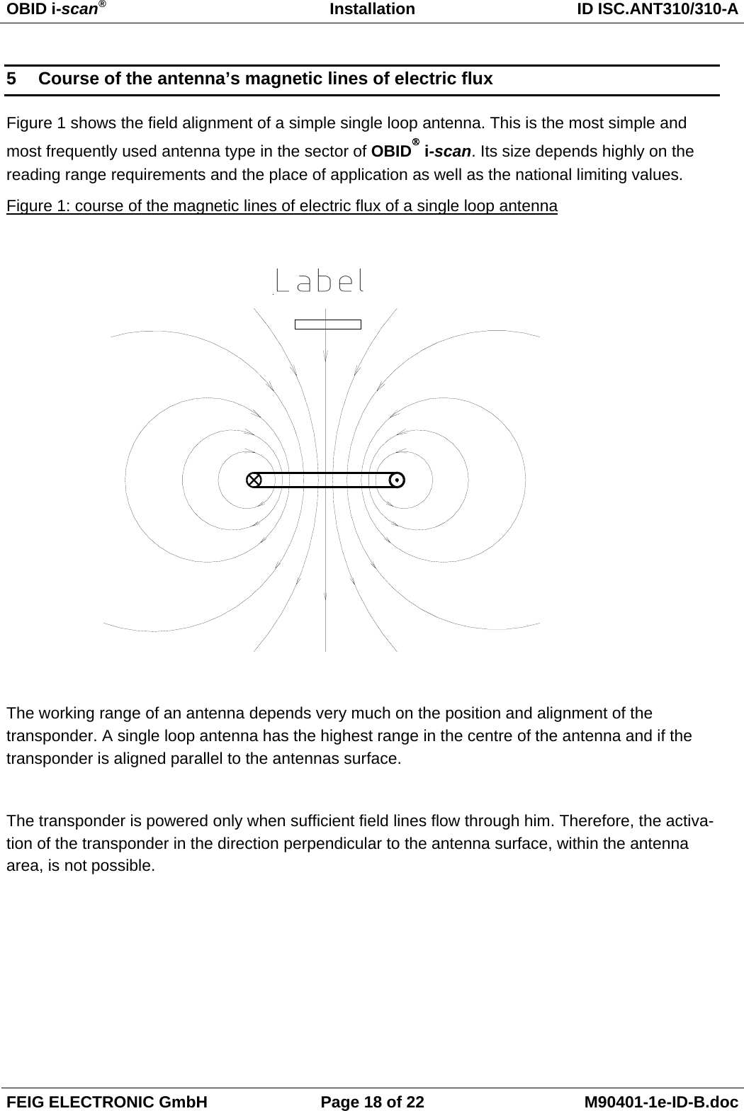
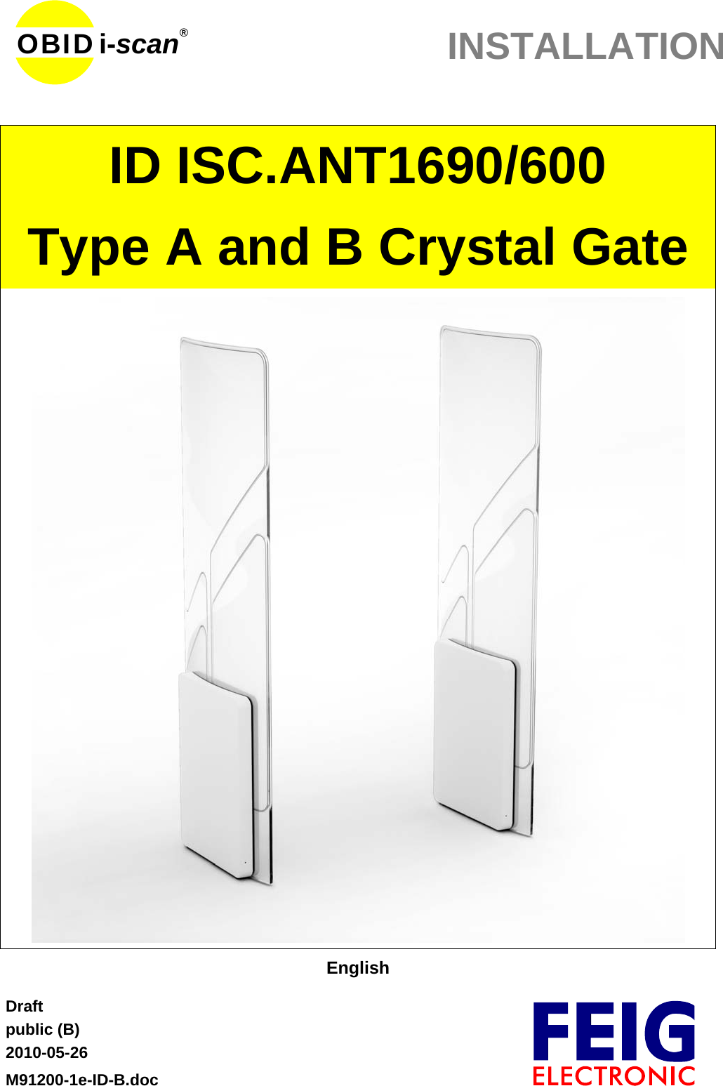
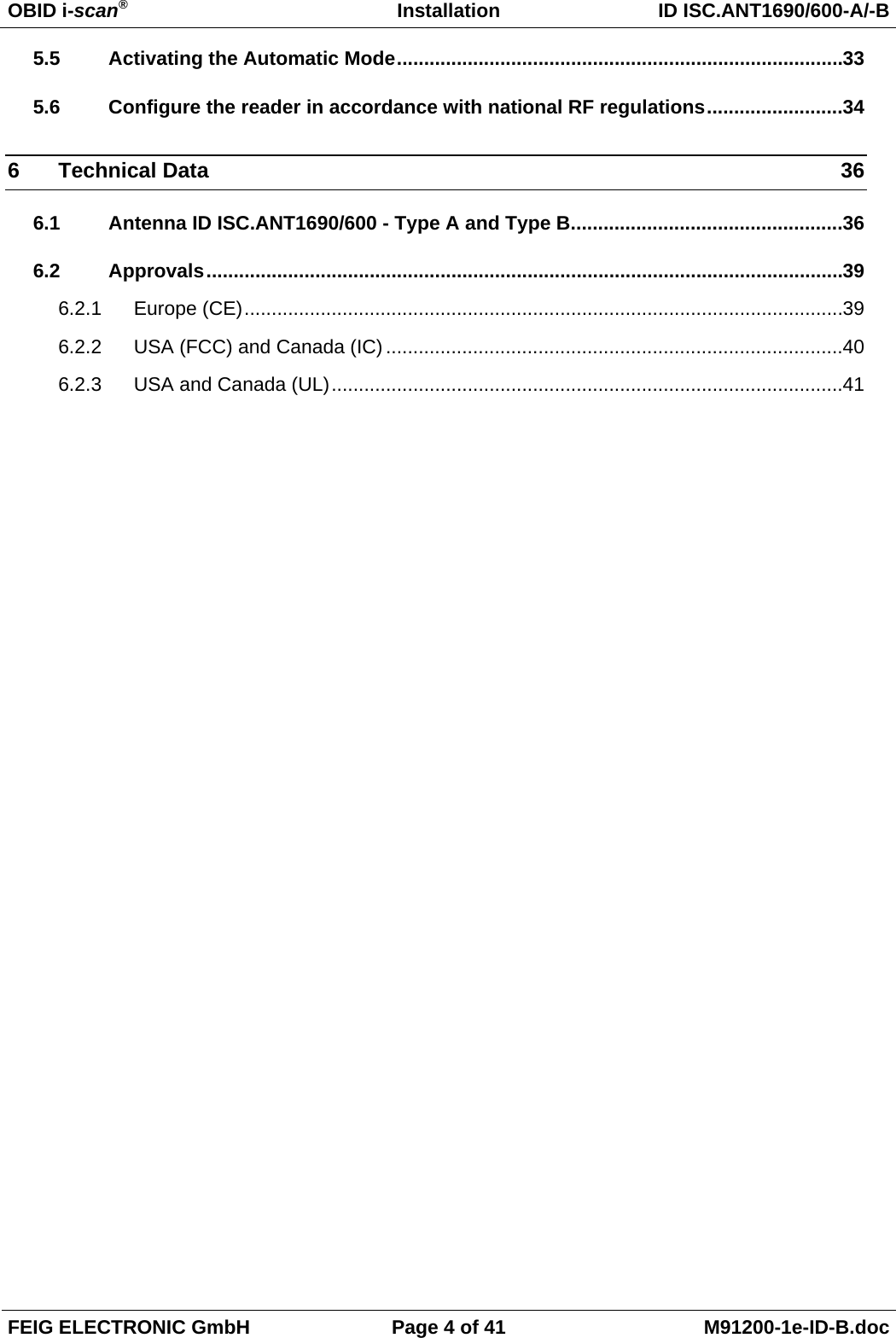
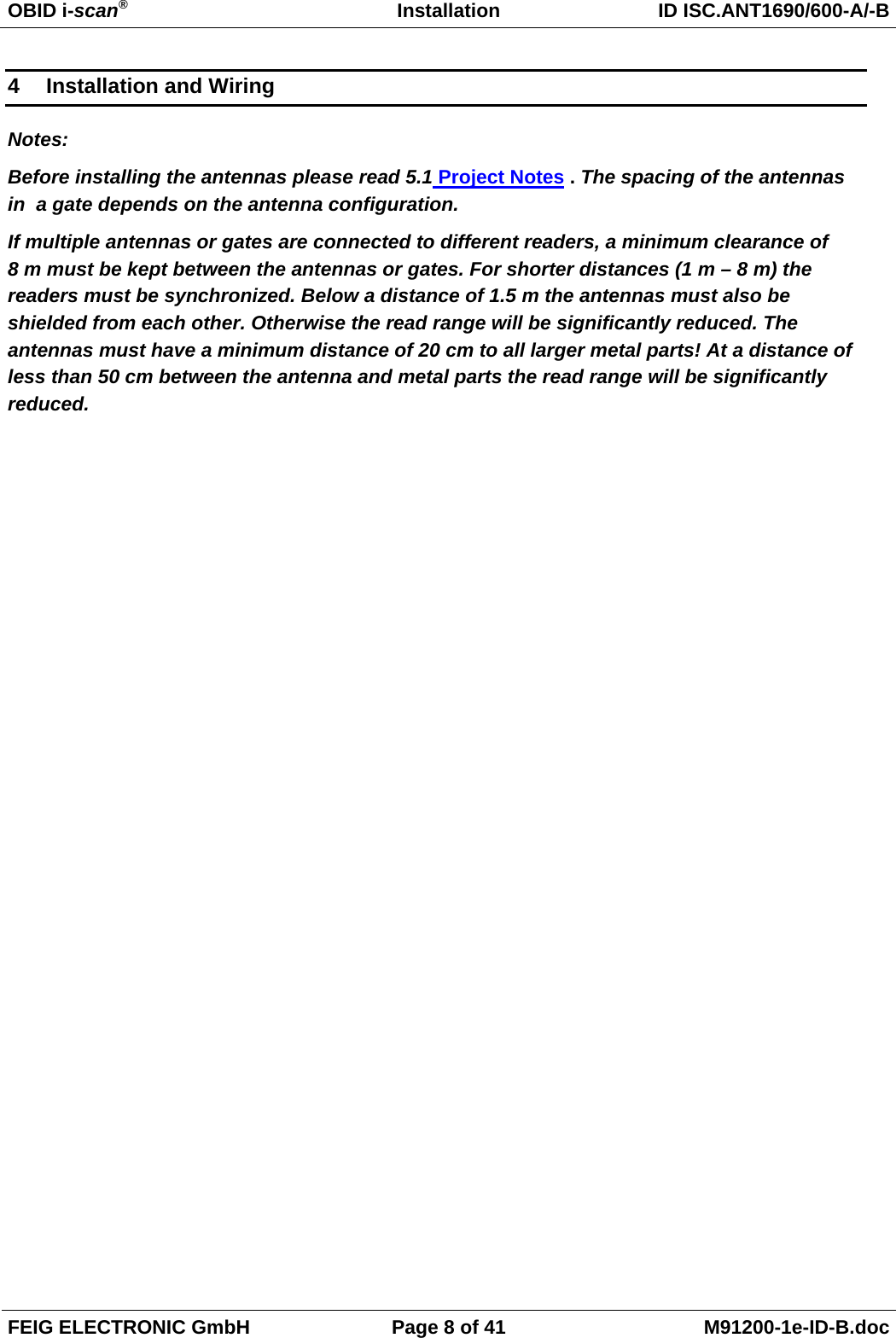
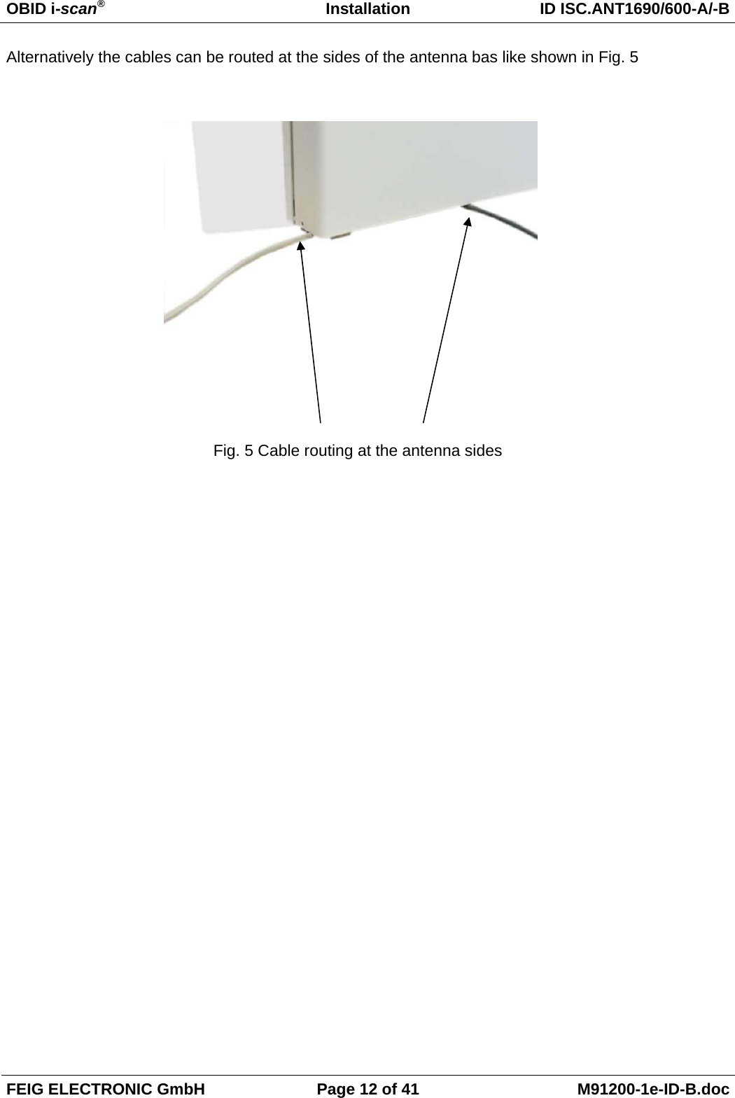
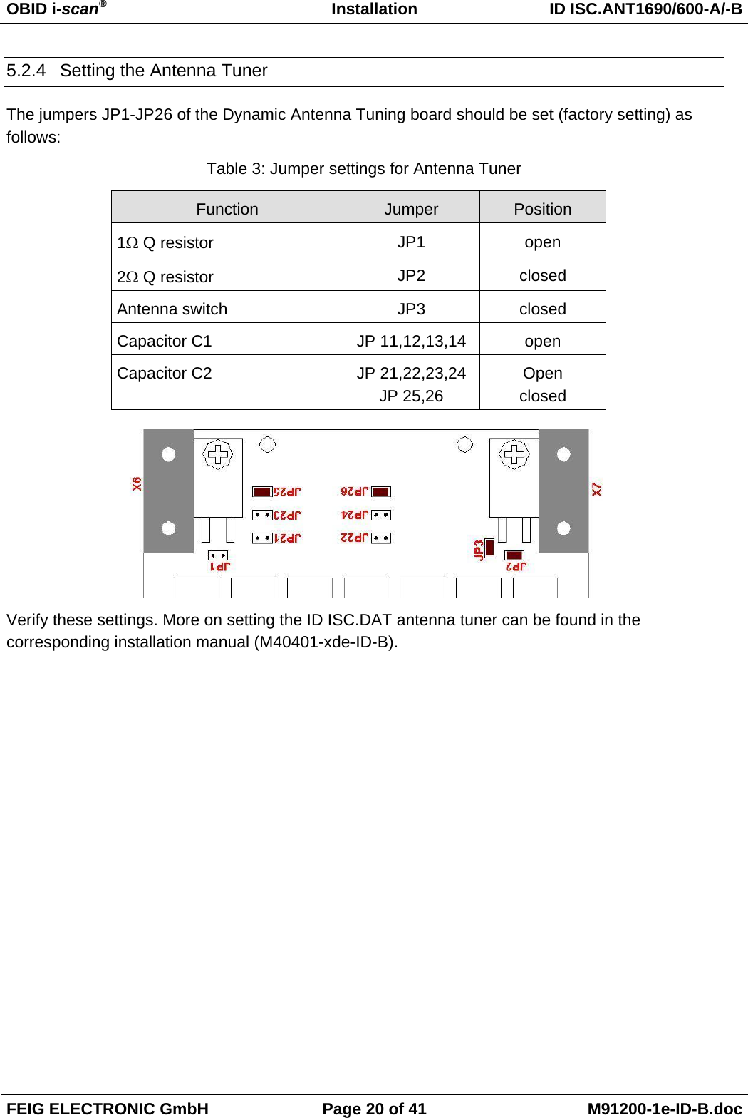
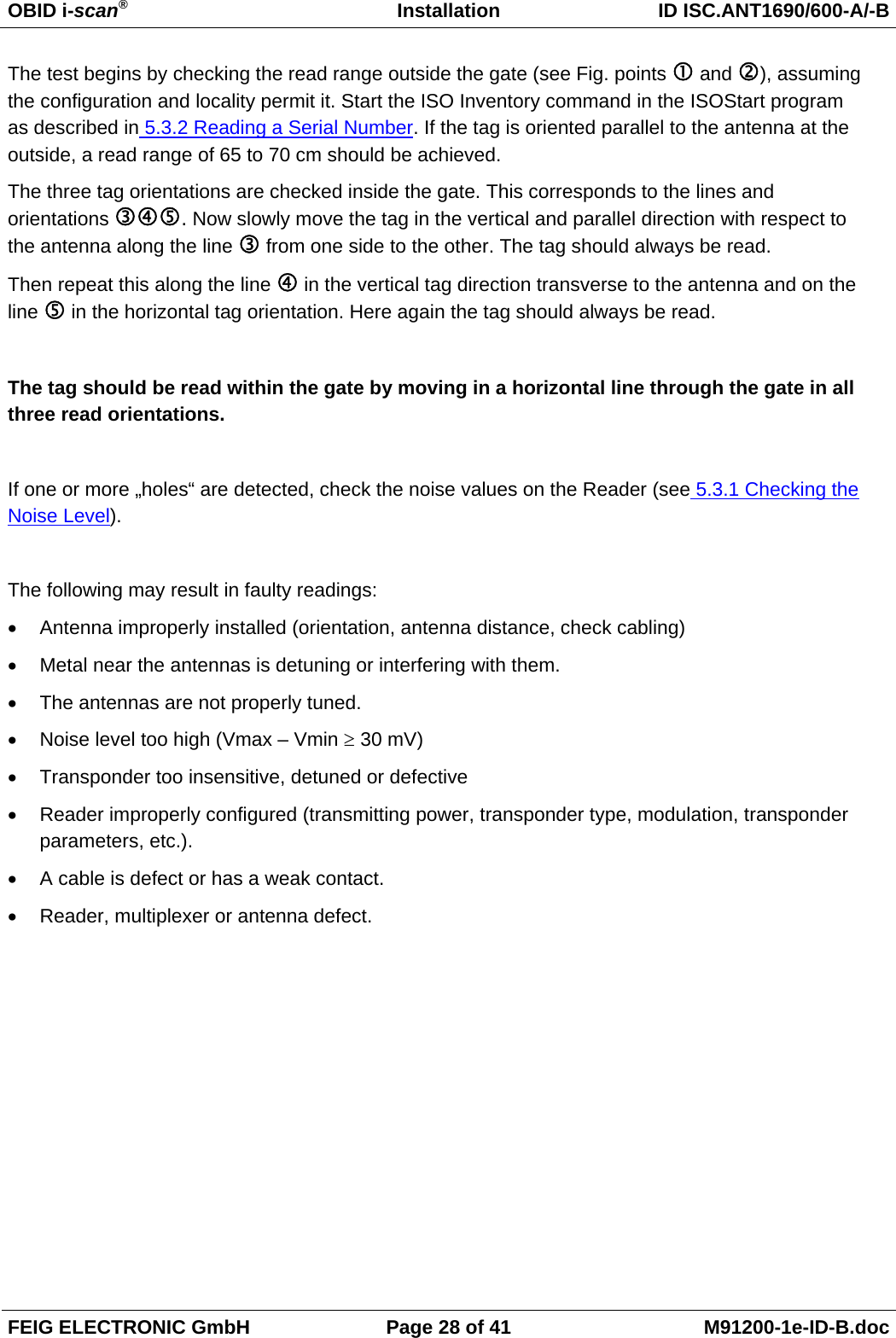
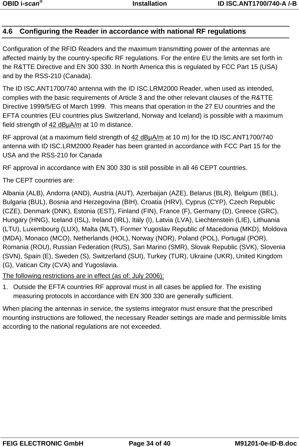
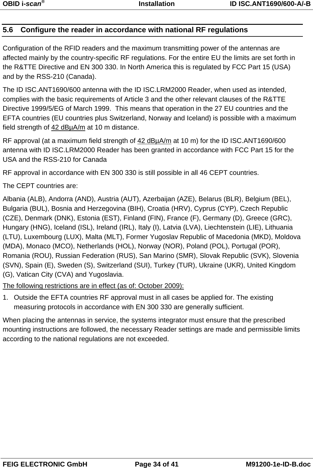
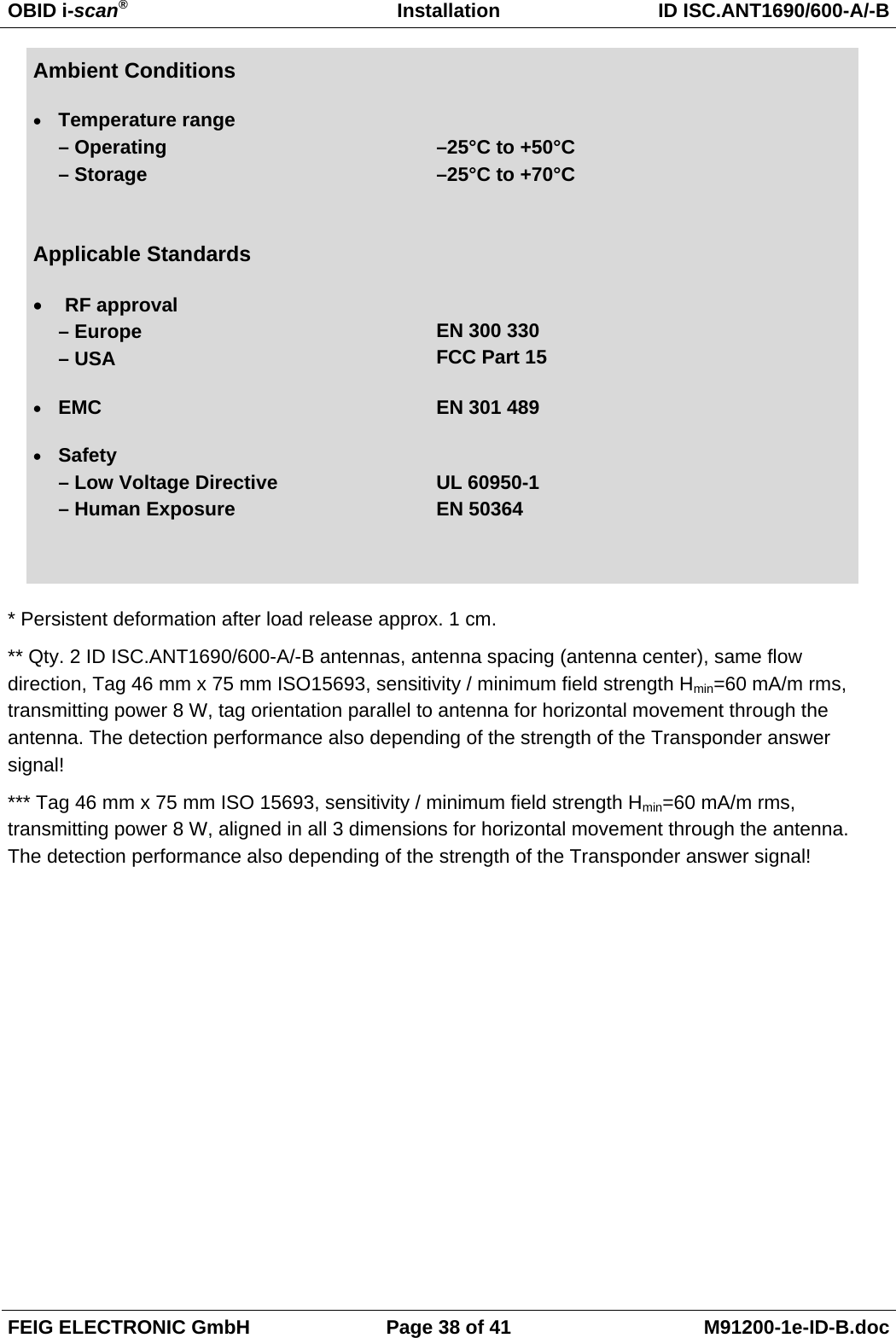
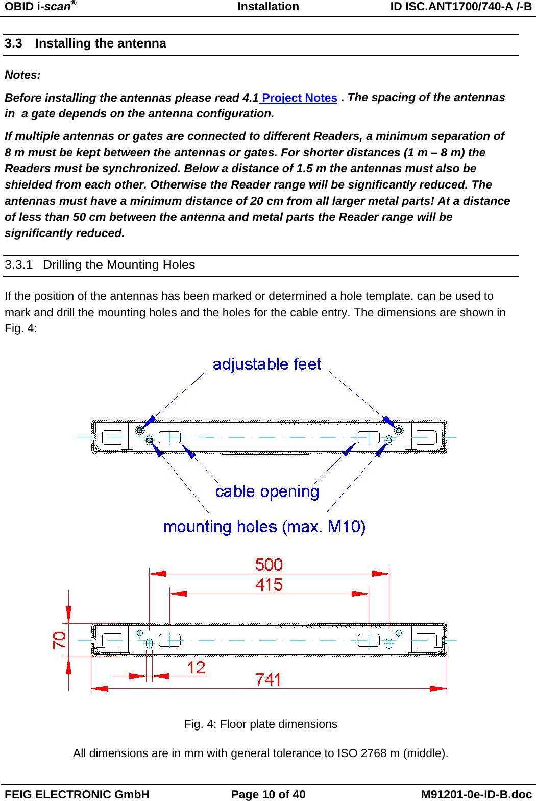
![OBID i-scan® Installation ID ISC.ANT1690/600-A/-B FEIG ELECTRONIC GmbH Page 31 of 41 M91200-1e-ID-B.doc 5.4.2 Programming a Transponder with the AFI Byte If the Transponders will remain on the object when leaving the storage location, they must first be cancelled. This is generally done by writing to a particular area of the Transponder. The AFI byte (Application Family Identifier) is useful for this purpose, since it is contained in nearly all Transponder models in the ISO15693 family. To cancel, simply write a different code to the Transponder than for valid Transponders which trigger an alarm. Step Action: Note: 1 Select „Commands“ 2 Place the Transponder in the antenna field (Antenna 1) Select [0x01] Inventory Mode: New Inventory Requested 3 Read UID by clicking on „Send“ 4 The serial number, DSFID and Transponder type are displayed in a window. Write down the serial number of the Transponder 5 Select „[0x27] Write AFI“ ADR: 1: addressed Serial Number: Select TransponderUID AFI: Desired AFI Number (not equal to 00) 6 Write AFI byte on to the transponder by click on „Send“](https://usermanual.wiki/Feig-Electronic/LRM2000-2/User-Guide-1292029-Page-53.png)
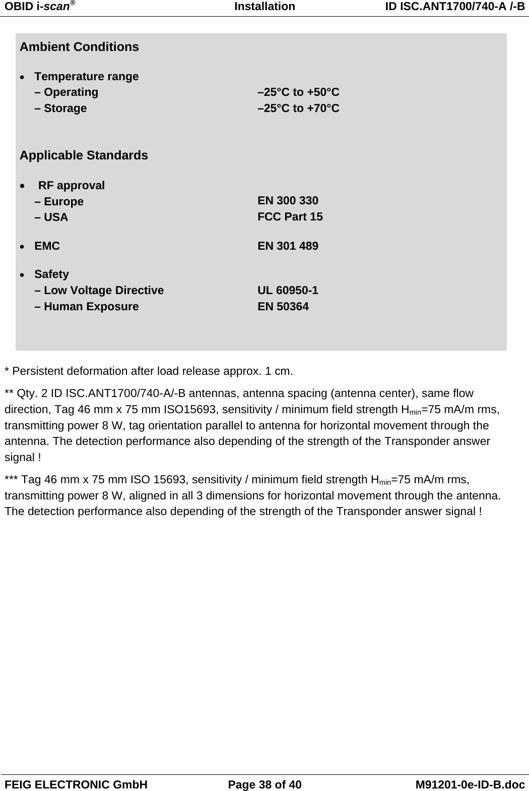
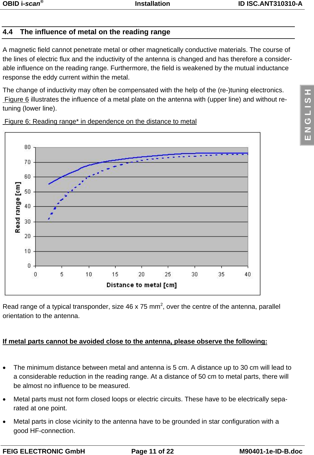
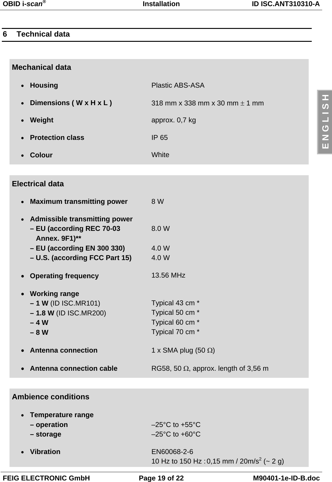
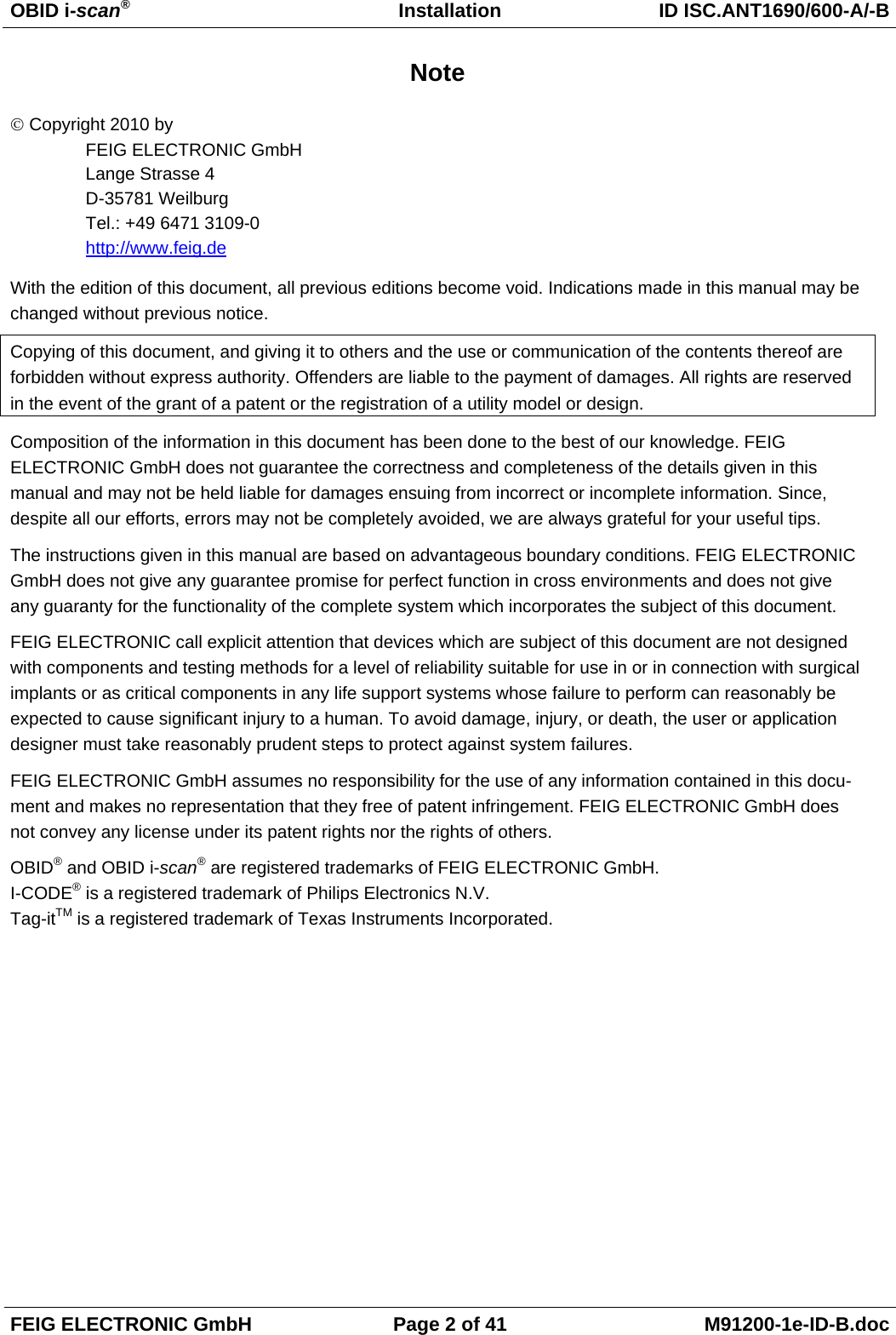
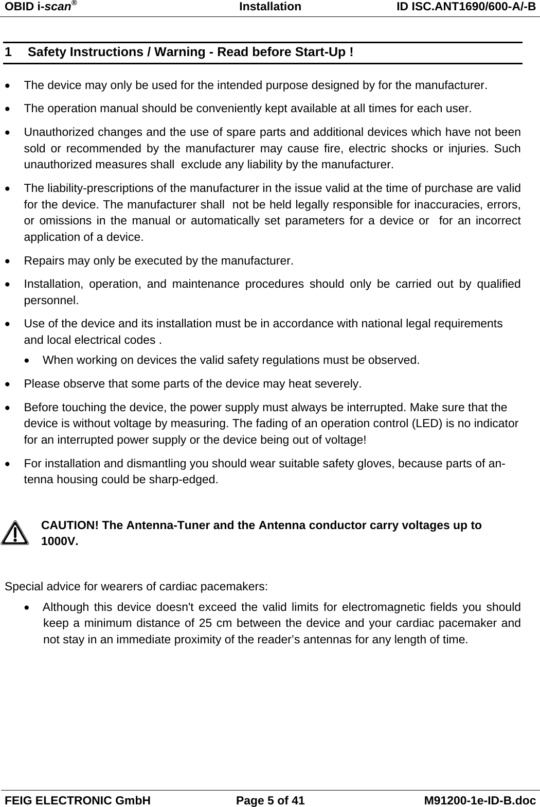
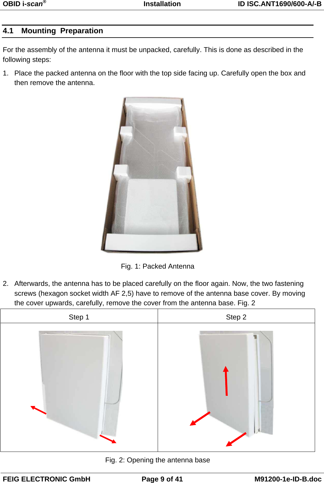
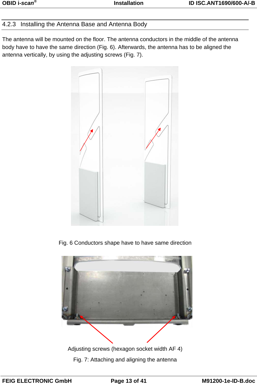
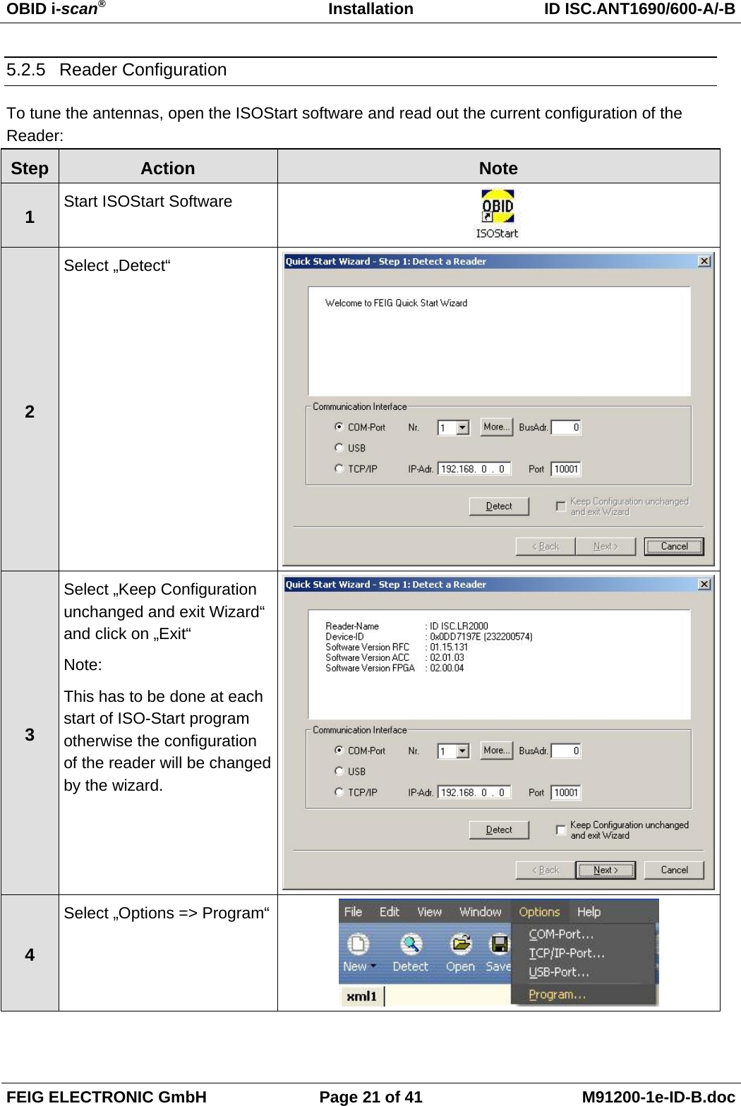
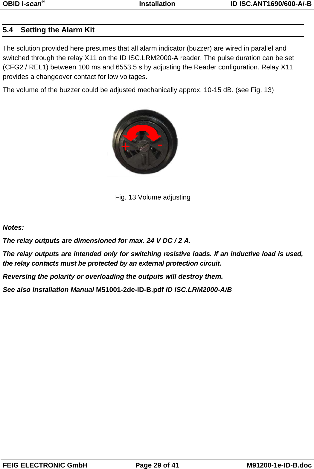
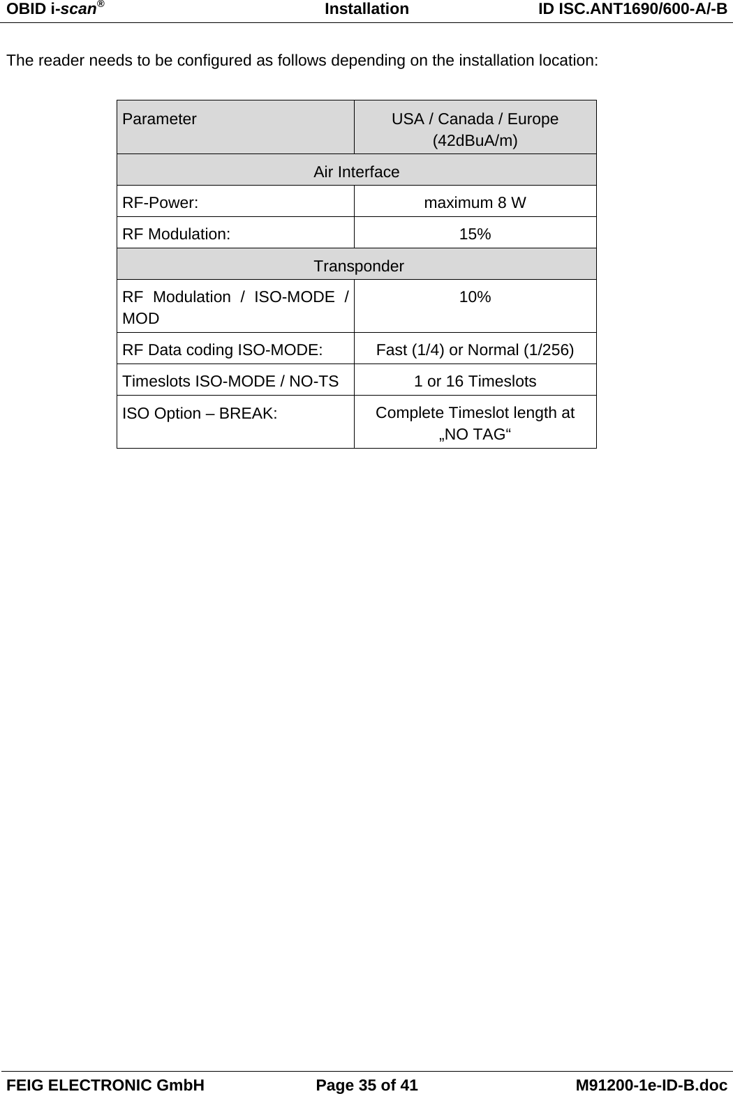
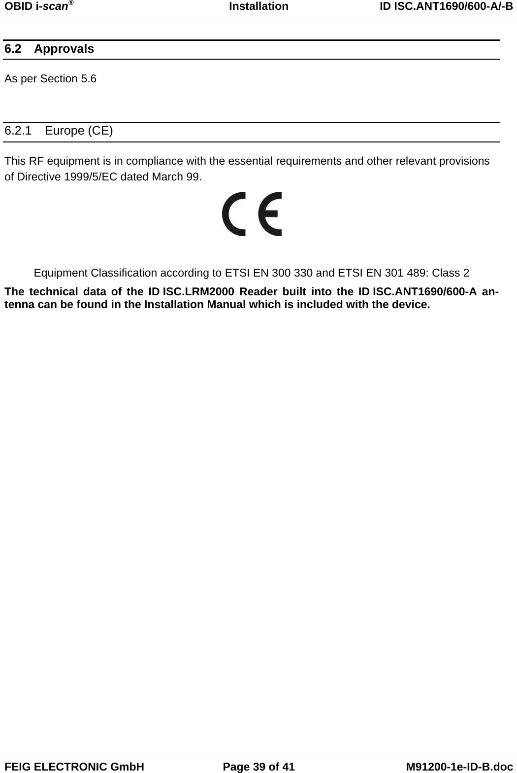
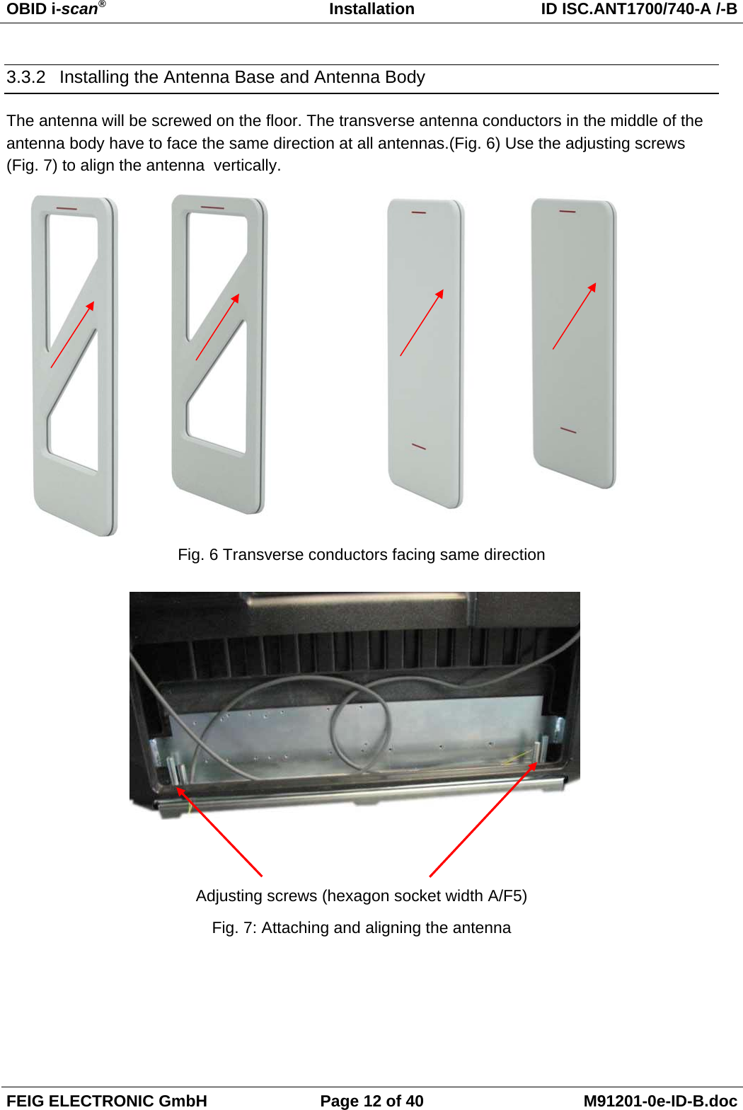
![OBID i-scan® Installation ID ISC.ANT1690/600-A/-B FEIG ELECTRONIC GmbH Page 32 of 41 M91200-1e-ID-B.doc 7 To verify, read AFI byte by using the command [0x2B] Get System Information](https://usermanual.wiki/Feig-Electronic/LRM2000-2/User-Guide-1292029-Page-54.png)
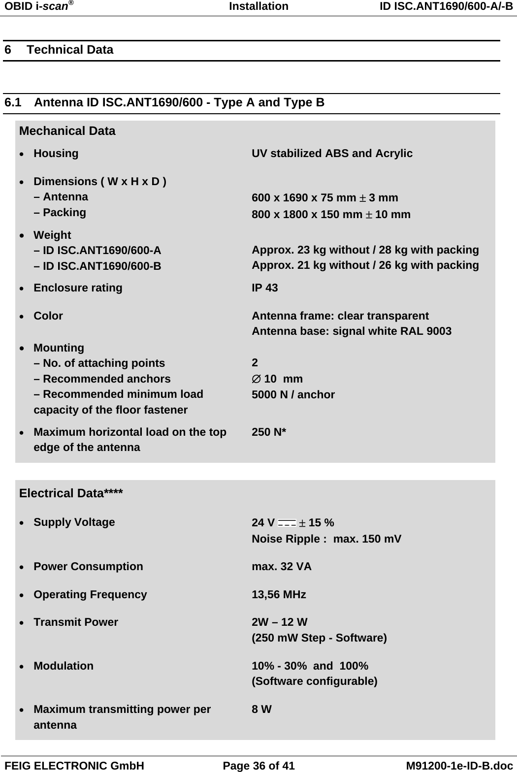
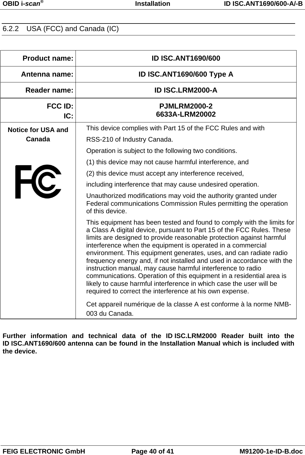

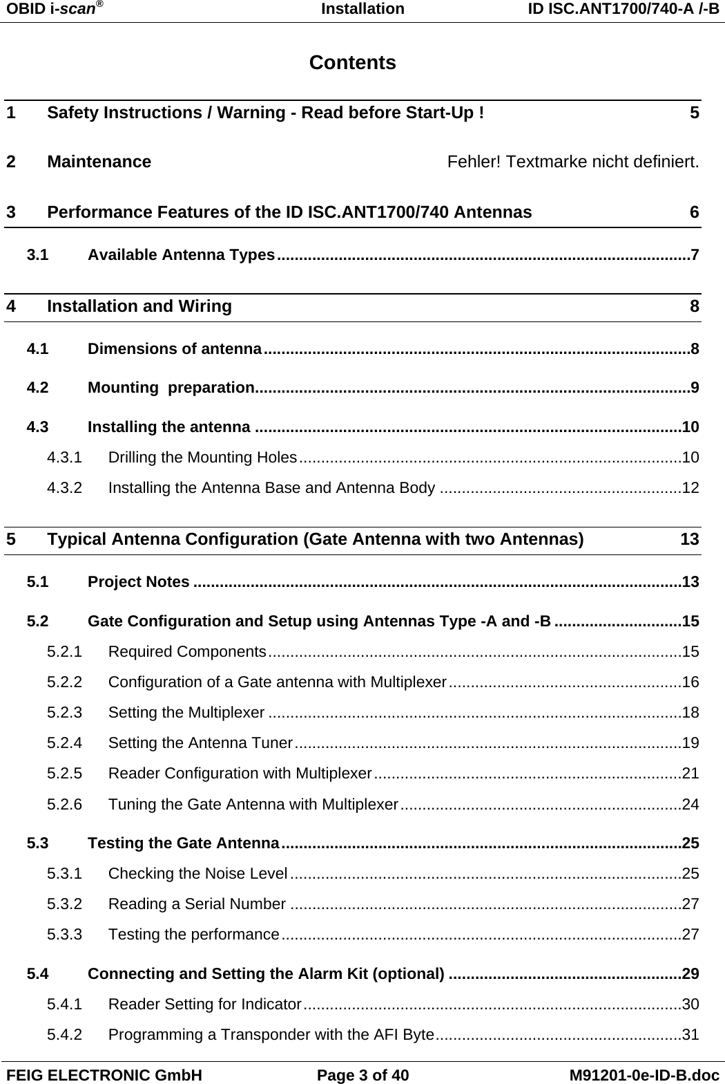
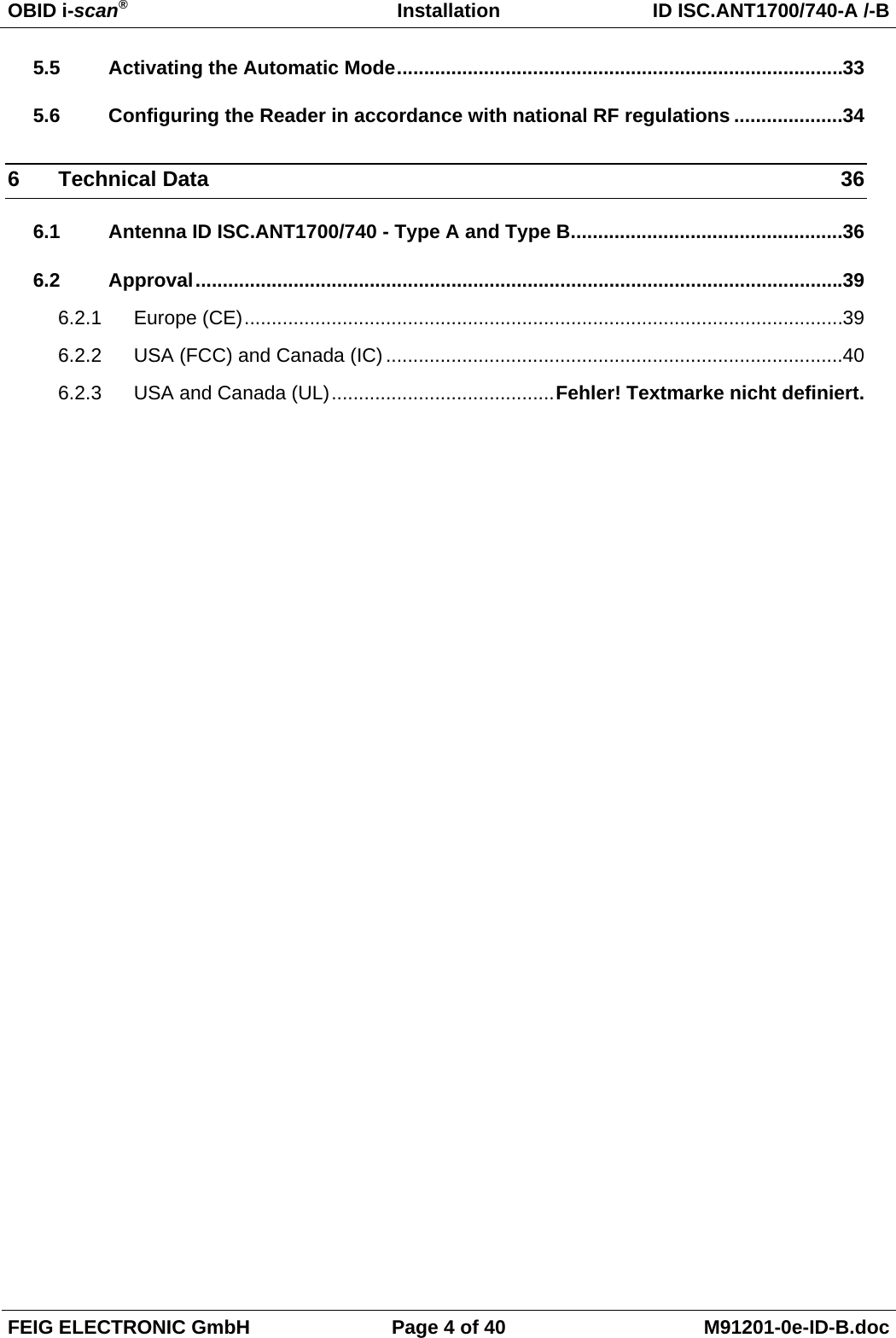
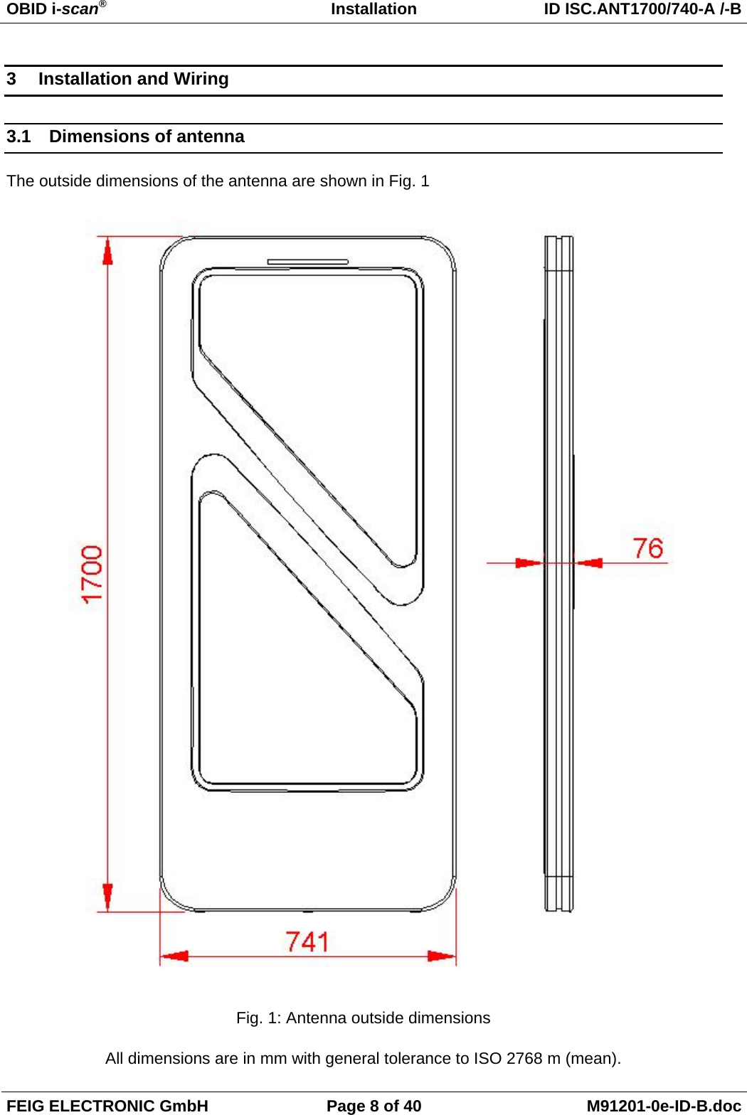

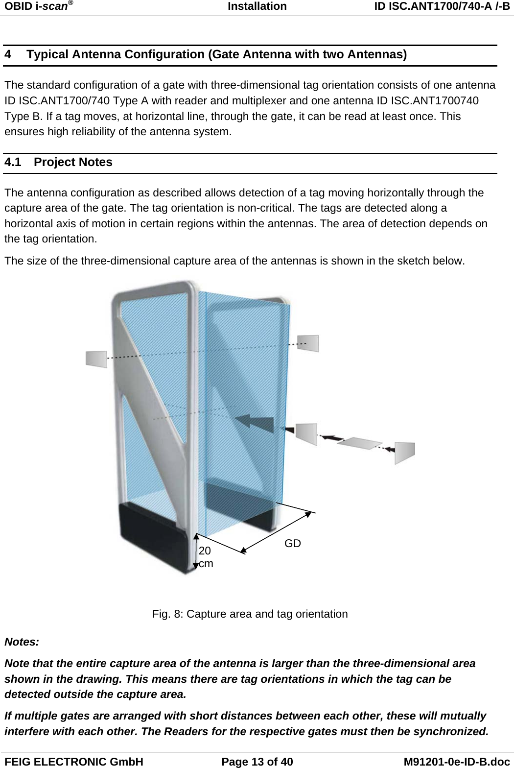
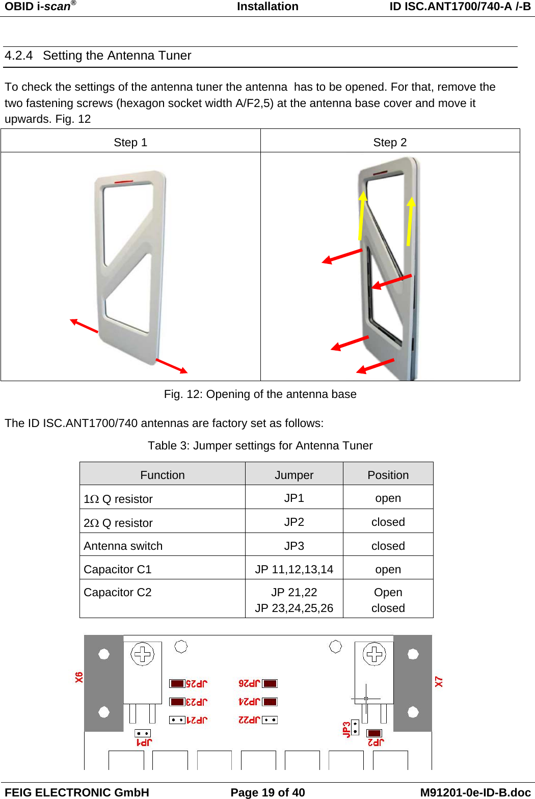

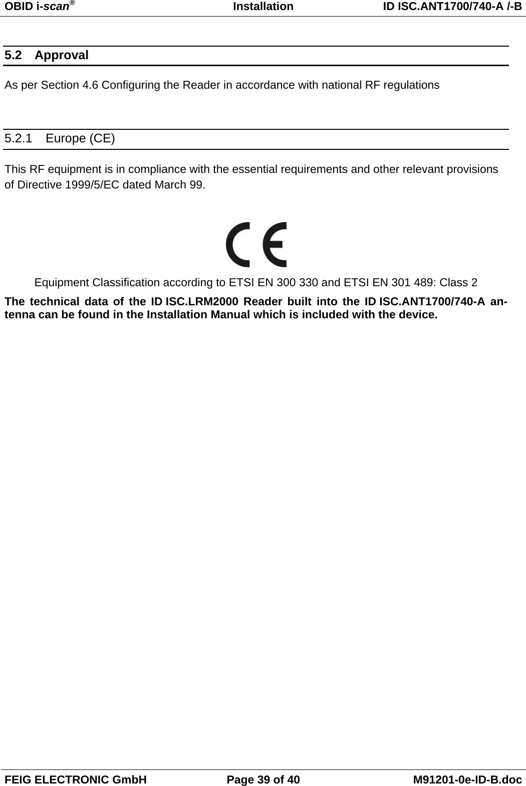
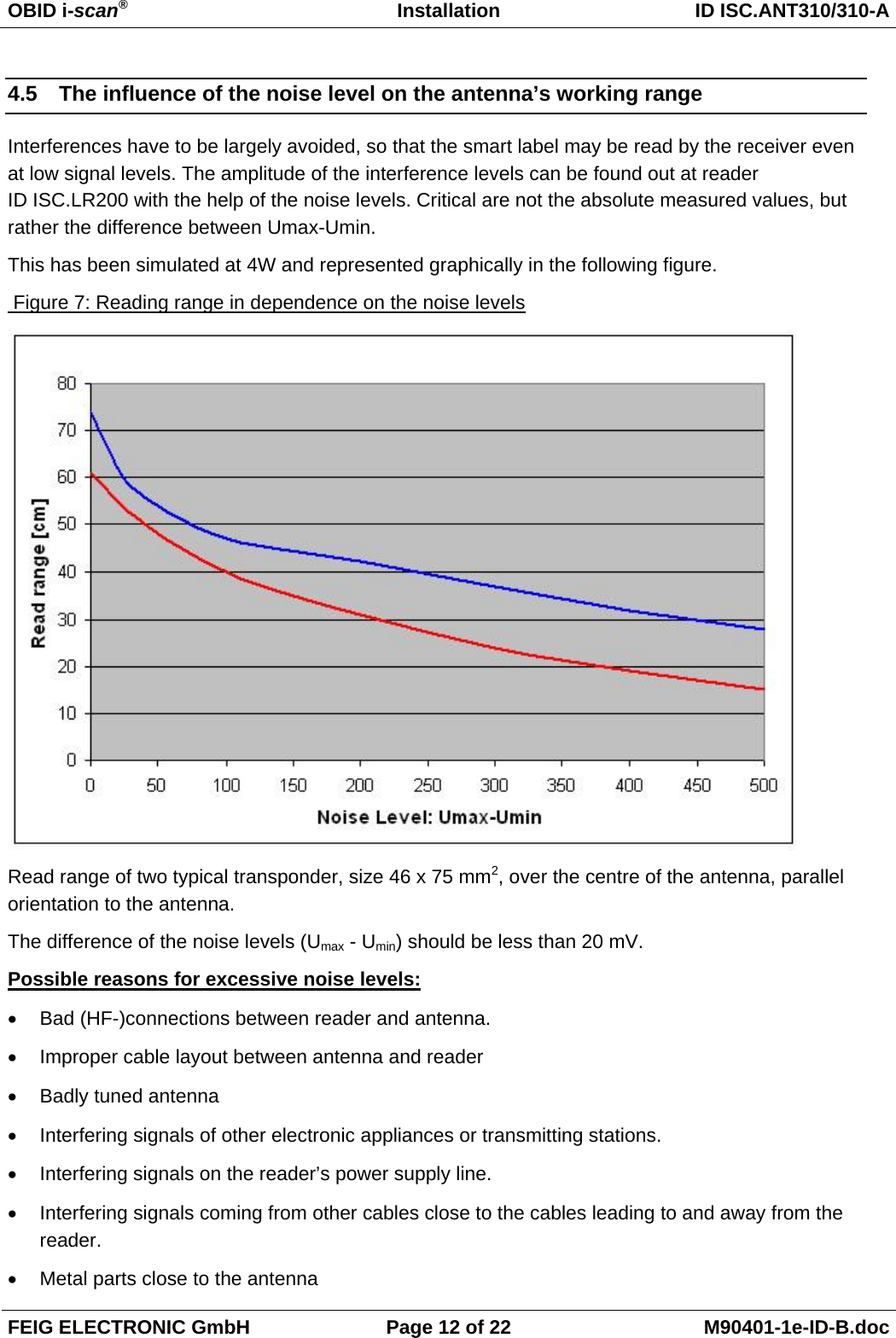
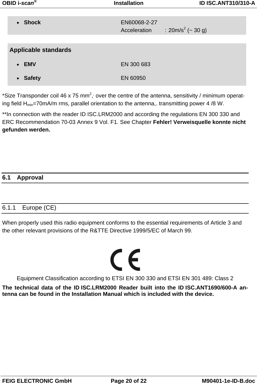
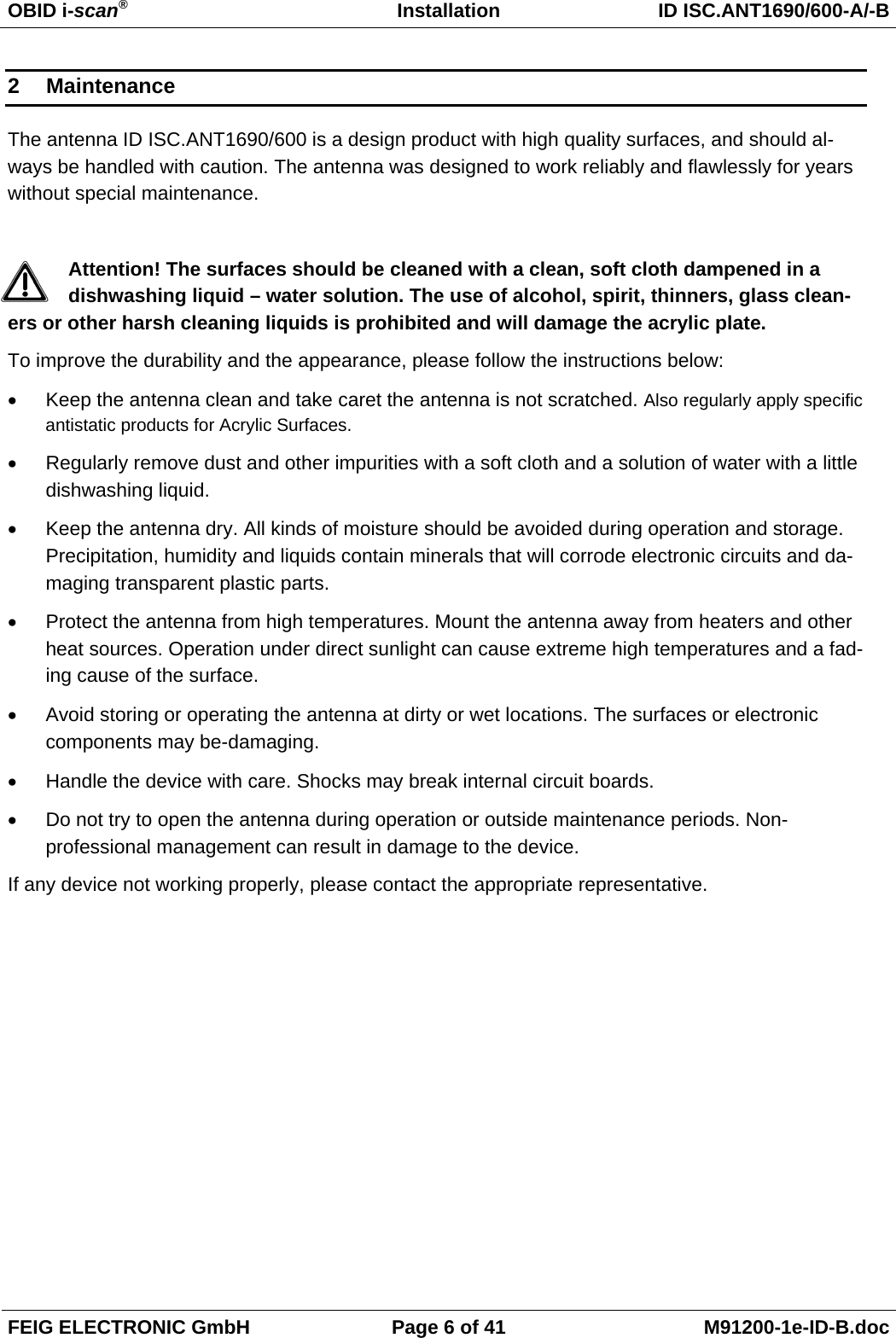
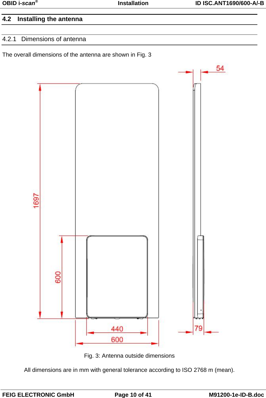
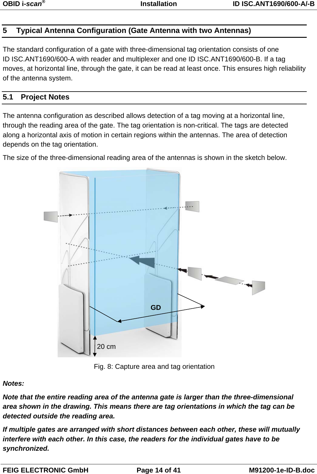
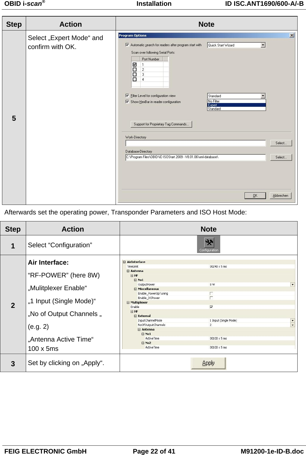
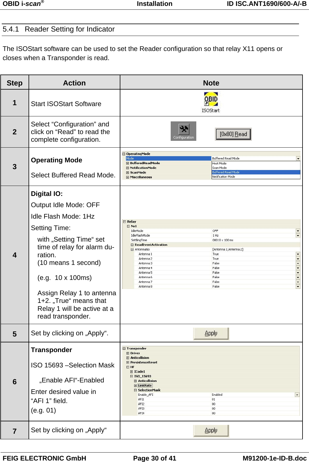
![OBID i-scan® Installation ID ISC.ANT1700/740-A /-B FEIG ELECTRONIC GmbH Page 31 of 40 M91201-0e-ID-B.doc 4.4.2 Programming a Transponder with the AFI Byte If the Transponders will remain on the object when leaving the storage location, they must first be cancelled. This is generally done by writing to a particular area of the Transponder. The AFI byte (Application Family Identifier) is useful for this purpose, since it is contained in nearly all Transponder models in the ISO15693 family. To cancel, simply write a different code to the Transponder than for valid Transponders which trigger an alarm. Step Action: Note: 1 Select „Commands“ 2 Place the Transponder in the antenna field (Antenna 1) Select [0x01] Inventory Mode: New Inventory Requested 3 Read UID by clicking on „Send“ 4 The serial number, DSFID and Transponder type are displayed in a window. Write down the serial number of the Transponder 5 Select „[0x27] Write AFI“ ADR: 1: addressed Serial Number: Select TransponderUID AFI: Desired AFI Number (not equal to 00) 6 Write AFI byte on to the transponder by click on „Send“](https://usermanual.wiki/Feig-Electronic/LRM2000-2/User-Guide-1292029-Page-94.png)
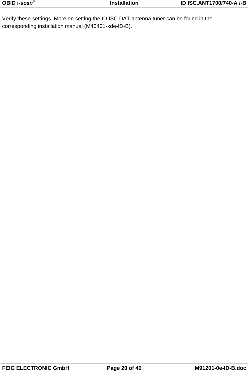
![OBID i-scan® Installation ID ISC.ANT1700/740-A /-B FEIG ELECTRONIC GmbH Page 32 of 40 M91201-0e-ID-B.doc 7 To verify, read AFI byte by using the command [0x2B] Get System Information](https://usermanual.wiki/Feig-Electronic/LRM2000-2/User-Guide-1292029-Page-95.png)