Feig Electronic LRM2000 RFID Transponder Reader System User Manual
Feig Electronic GmbH RFID Transponder Reader System
User Manual
MONTAGE
INSTALLATION
final
public (B)
2006-03-13
M51001-0de-ID-B.doc
OBI
D
i-scan
®
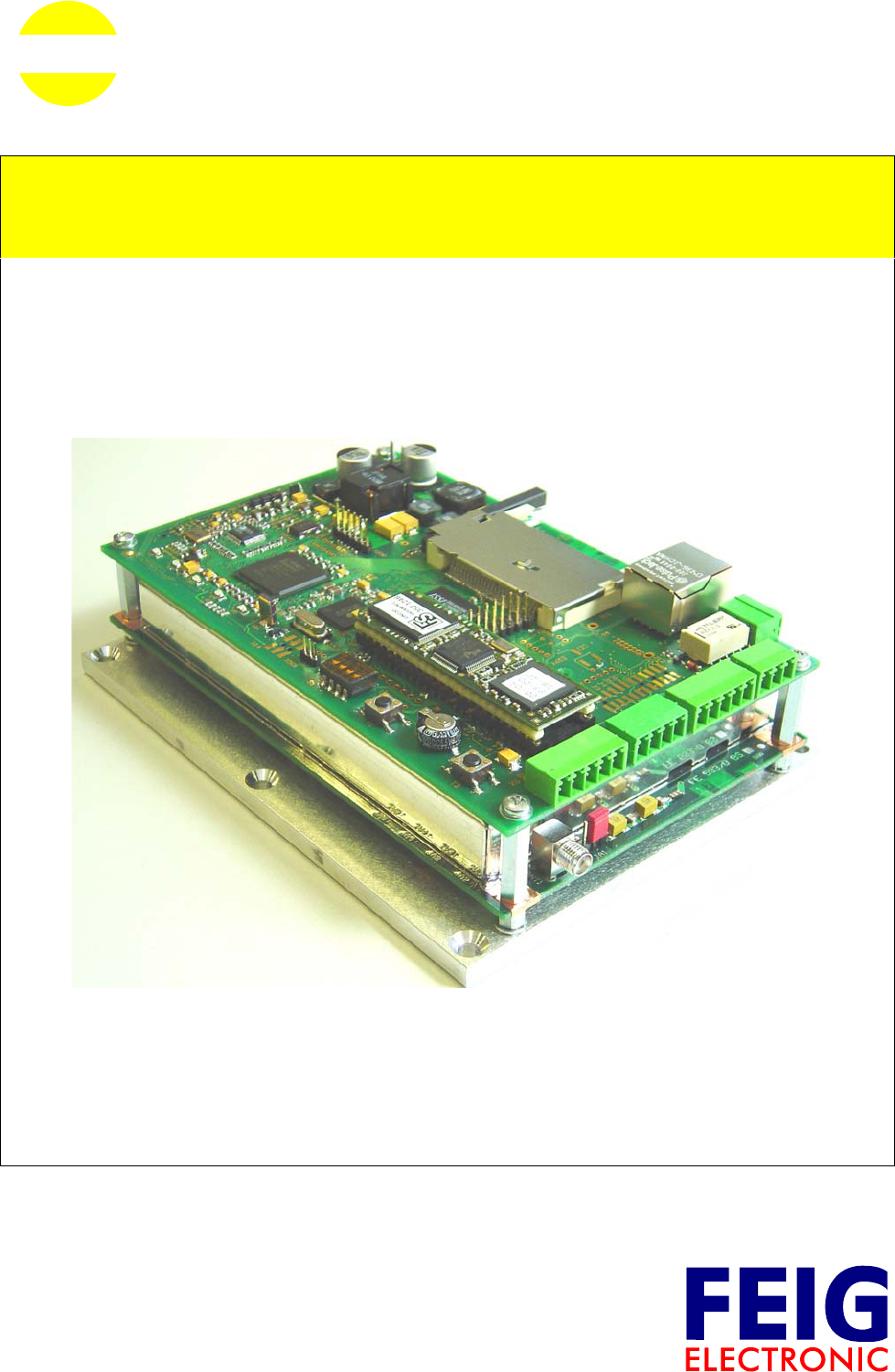
ID ISC.LRM2000
(deutsch / english)


OBID i-scan®Montage ID ISC.LRM2000
FEIG ELECTRONIC GmbH Seite 3 von 55 M51001-0de-ID-B.doc
D E U T S C H
Hinweis
© Copyright 2005 by
FEIG ELECTRONIC GmbH
Lange Straße 4
D-35781 Weilburg-Waldhausen
Tel.: +49 6471 3109-0
http://www.feig.de
Alle früheren Ausgaben verlieren mit dieser Ausgabe ihre Gültigkeit.
Die Angaben in diesem Dokument können ohne vorherige Ankündigung geändert werden.
Weitergabe sowie Vervielfältigung dieses Dokuments, Verwertung und Mitteilung ihres Inhalts sind nicht
gestattet, soweit nicht ausdrücklich zugestanden. Zuwiderhandlung verpflichtet zu Schadenersatz. Alle
Rechte für den Fall der Patenterteilung oder Gebrauchsmuster-Eintragung vorbehalten.
Die Zusammenstellung der Informationen in diesem Dokument erfolgt nach bestem Wissen und Gewissen.
FEIG ELECTRONIC GmbH übernimmt keine Gewährleistung für die Richtigkeit und Vollständigkeit der An-
gaben in diesem Dokument. Insbesondere kann FEIG ELECTRONIC GmbH nicht für Folgeschäden auf
Grund fehlerhafter oder unvollständiger Angaben haftbar gemacht werden. Da sich Fehler, trotz aller Bemü-
hungen nie vollständig vermeiden lassen, sind wir für Hinweise jederzeit dankbar.
Die in diesem Dokument gemachten Installationsempfehlungen gehen von günstigsten Rahmenbedingun-
gen aus. FEIG ELECTRONIC GmbH übernimmt keine Gewähr für die einwandfreie Funktion in systemfrem-
den Umgebungen.
FEIG ELECTRONIC GmbH übernimmt keine Gewährleistung dafür, dass die in diesem Dokument enthal-
tenden Informationen frei von fremden Schutzrechten sind. FEIG ELECTRONIC GmbH erteilt mit diesem
Dokument keine Lizenzen auf eigene oder fremde Patente oder andere Schutzrechte.
OBID® und OBID i-scan® ist ein eingetragenes Warenzeichen der FEIG ELECTRONIC GmbH
my-d® ist ein eingetragenes Warenzeichen der Infineon Technologies AG
I-CODE® und mifare® ist ein eingetragenes Warenzeichen der Philips Electronics N.V.
Tag-it™ ist ein Warenzeichen der Texas Instruments Incorporated

OBID i-scan®Montage ID ISC.LRM2000
FEIG ELECTRONIC GmbH Seite 4 von 55 M51001-0de-ID-B.doc
D E U T S C H
Inhalt
1 Sicherheits- und Warnhinweise - vor Inbetriebnahme unbedingt lesen 6
2 Leistungsmerkmale der Readerfamilie ID ISC.LRM2000 7
2.1 Leistungsmerkmale.......................................................................................................7
2.2 Verfügbare Readertypen...............................................................................................7
3 Montage und Anschluss 8
3.1 Anschlussklemmen.......................................................................................................9
3.2 Antennenanschluss ....................................................................................................10
3.3 Versorgungsspannung ...............................................................................................11
3.4 X6: Optokopplereingang und Optokopplerausgang................................................12
3.4.1 Optokopplerausgang (X6/1-2):......................................................................................13
3.4.2 Optokopplereingang (X6/3-4):.......................................................................................13
3.5 X9: Relais .....................................................................................................................14
3.6 X5: Readersynchronisation........................................................................................15
3.7 X14: Anschluss externer Diagnose-LEDs.................................................................16
3.8 Schnittstellen...............................................................................................................17
3.8.1 X8: RS232-Schnittstelle ................................................................................................17
3.8.2 X7: RS485/RS422 Schnittstelle.....................................................................................18
3.8.3 X11: LAN (nur Gerätevarianten mit ACC) ...................................................................19
3.8.4 X12: CompactFlash-Steckplatz (nur Gerätevarianten mit ACC) .................................19
4 Bedien- und Anzeigeelemente 20
4.1 LEDs .............................................................................................................................20
4.2 Taster / Schalter ..........................................................................................................21
5 Inbetriebnahme 22
5.1 Schnittstellenkonfiguration........................................................................................22
5.1.1 RS485/RS422 ...............................................................................................................22

OBID i-scan®Montage ID ISC.LRM2000
FEIG ELECTRONIC GmbH Seite 5 von 55 M51001-0de-ID-B.doc
D E U T S C H
5.1.2 Netzwerkanschluss - LAN .............................................................................................24
5.1.3 Netzwerkanschluss - WLAN..........................................................................................25
6 Funkzulassungen 26
6.1 Europa (CE)..................................................................................................................26
6.2 USA (FCC) ....................................................................................................................26
7 Technische Daten 27

OBID i-scan®Montage ID ISC.LRM2000
FEIG ELECTRONIC GmbH Seite 6 von 55 M51001-0de-ID-B.doc
D E U T S C H
1 Sicherheits- und Warnhinweise - vor Inbetriebnahme unbedingt lesen
• Das Gerät darf nur für den vom Hersteller vorgesehenen Zweck verwendet werden.
• Die Bedienungsanleitung ist zugriffsfähig aufzubewahren und jedem Benutzer auszuhändigen.
• Unzulässige Veränderungen und die Verwendung von Ersatzteilen und Zusatzeinrichtungen,
die nicht vom Hersteller des Gerätes verkauft oder empfohlen werden, können Brände, elektri-
sche Schläge und Verletzungen verursachen. Solche Maßnahmen führen daher zu einem
Ausschluss der Haftung und der Hersteller übernimmt keine Gewährleistung.
• Für das Gerät gelten die Gewährleistungsbestimmungen des Herstellers in der zum Zeitpunkt
des Kaufs gültigen Fassung. Für eine ungeeignete, falsche manuelle oder automatische Ein-
stellung von Parametern für ein Gerät bzw. ungeeignete Verwendung eines Gerätes wird keine
Haftung übernommen.
• Reparaturen dürfen nur vom Hersteller durchgeführt werden.
• Anschluss-, Inbetriebnahme-, Wartungs-, und sonstige Arbeiten am Gerät dürfen nur von Elekt-
rofachkräften mit einschlägiger Ausbildung erfolgen.
• Alle Arbeiten am Gerät und dessen Aufstellung müssen in Übereinstimmung mit den nationa-
len elektrischen Bestimmungen und den örtlichen Vorschriften durchgeführt werden.
• Beim Arbeiten an dem Gerät müssen die jeweils gültigen Sicherheitsvorschriften beachtet wer-
den.
• Besonderer Hinweis für Träger von Herzschrittmachern:
Obwohl dieses Gerät die zulässigen Grenzwerte für elektromagnetische Felder nicht über-
schreitet, sollten Sie einen Mindestabstand von 25 cm zwischen dem Gerät und Ihrem Herz-
schrittmacher einhalten und sich nicht für längere Zeit in unmittelbarer Nähe des Geräts bzw.
der Antenne aufhalten.

OBID i-scan®Montage ID ISC.LRM2000
FEIG ELECTRONIC GmbH Seite 7 von 55 M51001-0de-ID-B.doc
D E U T S C H
2 Leistungsmerkmale der Readerfamilie ID ISC.LRM2000
2.1 Leistungsmerkmale
Der Reader ist für das Lesen von passiven Datenträgern, sogenannten „Smart Labels“, mit einer
Betriebsfrequenz von 13,56 MHz entwickelt.
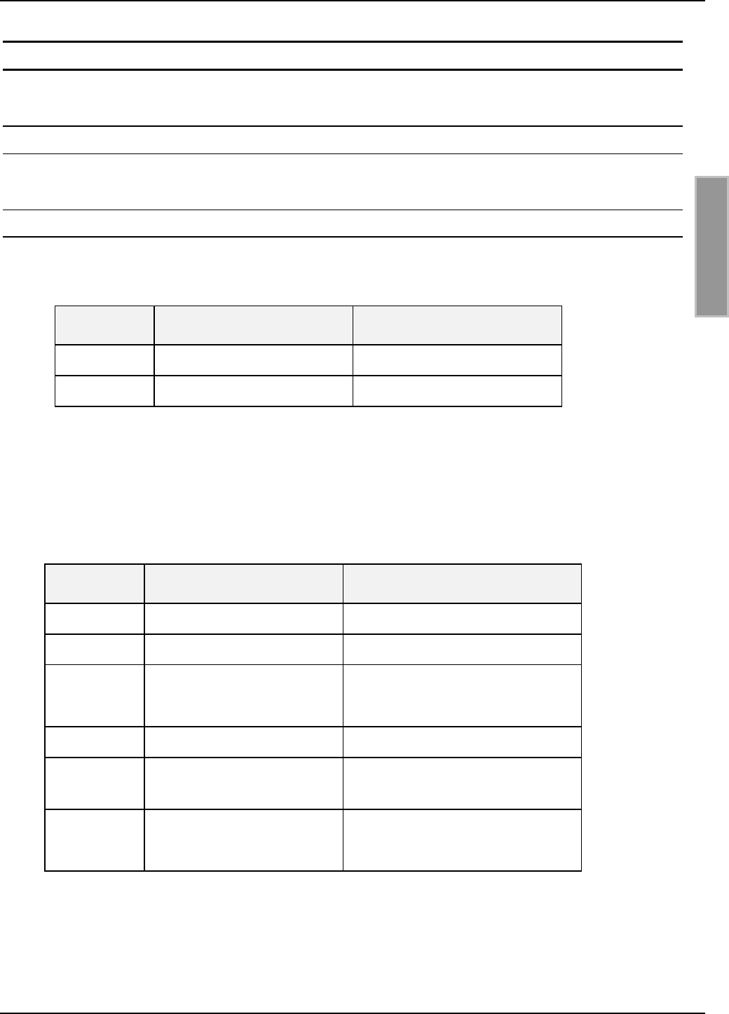
2.2 Verfügbare Readertypen
Folgende Readermodule sind z.Z. verfügbar:
Readermodultyp Beschreibung
ID ISC.LRM2000-A Modulvariante mit ACC
ID ISC.LRM2000-B Modulvariante ohne ACC
Tabelle 2-1: Readermodultypen
Reader type Description
ID ISC.LR2000-A Device version with ACC and Plastic Enclosure
Table 2-2: Reader types
OBID i-scan®Montage ID ISC.LRM2000
FEIG ELECTRONIC GmbH Seite 8 von 55 M51001-0de-ID-B.doc
D E U T S C H
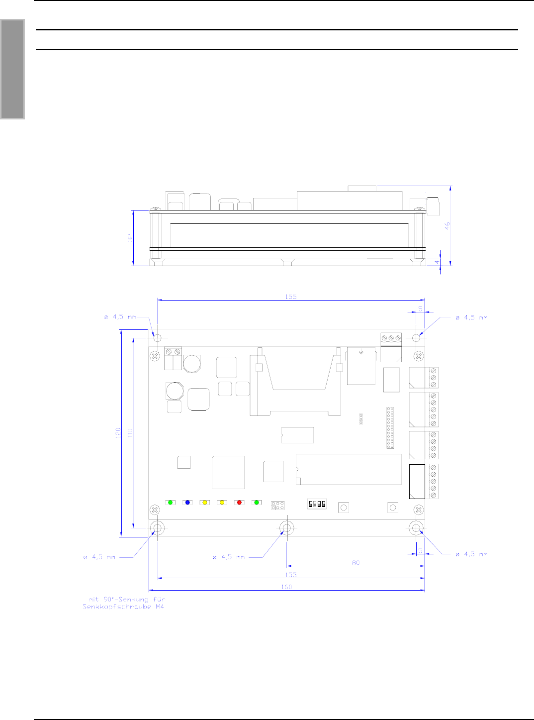
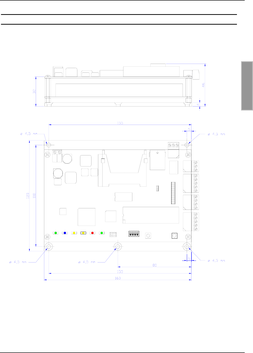
3 Montage und Anschluss
Das Reader-Modul ist für die Montage auf einem Kühlkörper konzipiert. Für die Befestigung befin-
det sich in den vier Ecken der Trägerplatte jeweils eine Bohrung mit dem ∅ 4,5 mm (siehe
Bild 3-1).
Bild 3-1: Maßzeichnung des Reader-Moduls ID ISC.LRM2000
* * *
*
OBID i-scan®Montage ID ISC.LRM2000
FEIG ELECTRONIC GmbH Seite 9 von 55 M51001-0de-ID-B.doc
D E U T S C H
Für die Ausnutzung der vollen Leistungsfähigkeit des Reader-Moduls sollte der verwendete Kühl-
körper einen Wärmewiderstand RThK von maximal 1,0 K/W besitzen. Bei der Montage des Reader-
Moduls auf den Kühlkörper ist auf einen möglichst geringen Wärmeübergangswiderstand zwischen
Trägerplatte und Kühlkörper zu achten. Die Verwendung von Wärmeleitpaste wird empfohlen.
Bei korrekt abgestimmter Antenne und ausreichender Luftkonvektion entlang der Montageplatte
kann der ID ISC.LRM2000 auch ohne zusätzlichen Kühlkörper bis zu einer Leistung von 2W be-
trieben werden. Hierbei ist jedoch zu beachten, dass eine Verstimmung der Antenne zu einer zu-
sätzlichen Erwärmung des Readers führt. In diesem Falle regelt der Reader seine Ausgangsleis-
tung zurück bis die obere Grenztemperatur seiner Endstufe wieder erreicht ist.
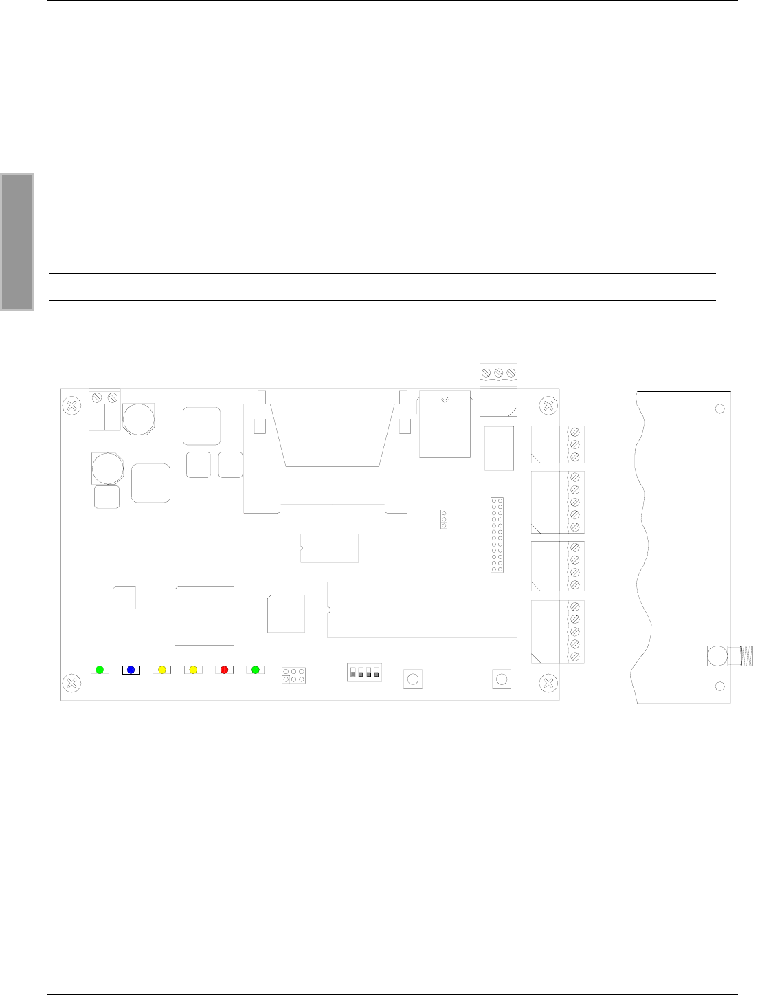
3.1 Anschlussklemmen
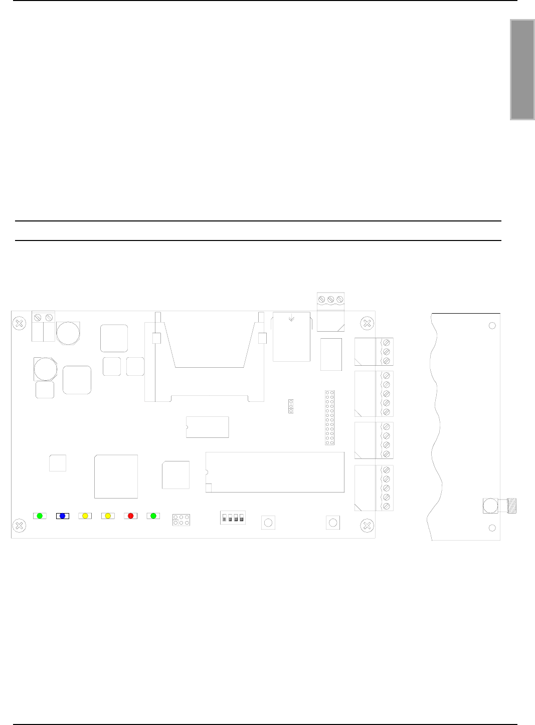
Bild 3-2 zeigt die Anschlussklemmen und Bedienelemente des ID ISC.LRM2000.
Bild 3-2: Anschlussklemmen des Readers
V1 V2 V3 V4 V5 V6
T1 T2
S1
X14
J20
X12
X13 X11
X9
J12
J11
J10
J9
J8
J7
J6
J5
J4
J3
J2
J1
X8
X7
X6
X5
ACC-Modul
ANT1
OBID i-scan®Montage ID ISC.LRM2000
FEIG ELECTRONIC GmbH Seite 10 von 55 M51001-0de-ID-B.doc
D E U T S C H
3.2 Antennenanschluss
Zum Anschluss der Antenne an dem ID ISC.LRM2000 befindet sich auf der unteren Leiterplatte die
SMA-Buchse "ANT1".
Aktive externe Funktionseinheiten (z.B. ID ISC.DAT) können zusätzlich über den Antennenan-
schluss mit 8 V DC versorgt werden. Die maximale Stromaufnahme darf dabei 150mA nicht
überschreiten.
Das maximale Anzugsdrehmoment der SMA-Buchse beträgt 0,45 Nm.
Achtung:
Höhere Anzugsdrehmomente führen zur Zerstörung der Buchse.
Klemme Beschreibung
ANT1 Anschluss der externen Antenne
(Eingangsimpedanz 50Ω)
Tabelle 3-1: Anschluss der externen Antenne
Hinweise:
• Das Stehwellenverhältnis VSWR der Antenne sollte den Wert 1,2 nicht überschreiten.
• Die optimale Betriebsgüte der Antenne sollte im Bereich QB = 10...30 liegen. Zur Ermitt-
lung der Betriebsgüte muss die Antenne mit einer 50Ω-Quelle, z.B. einem Network Ana-
lyzer oder einem Frequenzgenerator, versorgt werden.
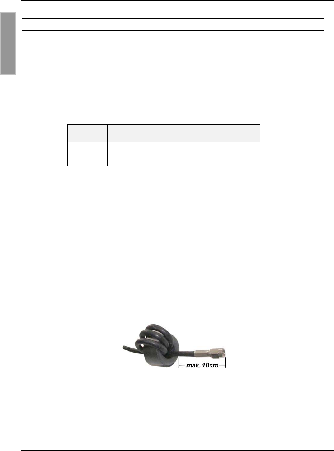
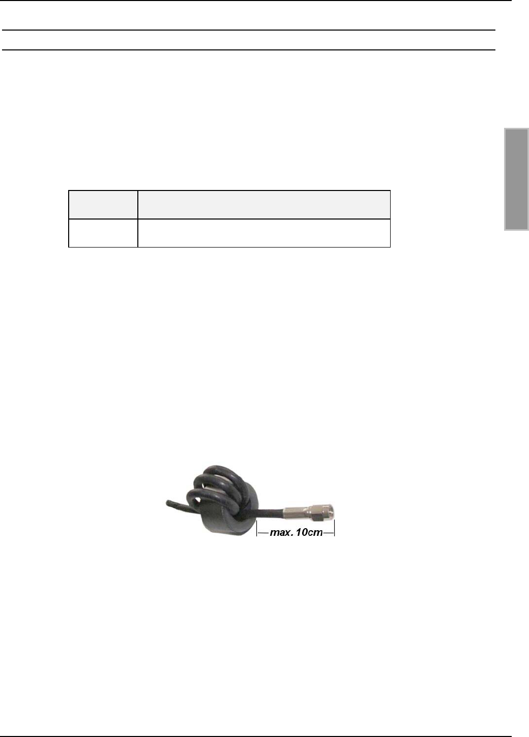
• Zur Vermeidung extern eingekoppelter Störungen sollte die Antennenzuleitung dem bei-
gefügten EMV-Ringkernferrit ∅ 28 mm x 20 mm versehen werden. Hierzu ist die Anten-
nenzuleitung mindestens vier mal, eng anliegend durch den EMV-Ringkernferrit zu füh-
ren. Der Abstand zwischen Readeranschluss ANT1 und Ringkern sollte dabei maximal
10 cm betragen (siehe Bild 3-3).
• Beim Anschluss der Antenne ist darauf zu achten, dass diese die zulässigen Grenzwerte
der nationalen Vorschriften bezüglich Funkanlagen nicht überschreitet.
Bild 3-3: Antennenkabel mit EMV-Ringkernferrit
OBID i-scan®Montage ID ISC.LRM2000
FEIG ELECTRONIC GmbH Seite 11 von 55 M51001-0de-ID-B.doc
D E U T S C H
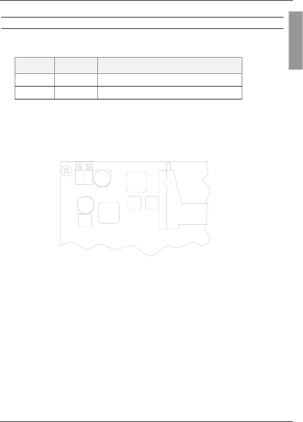
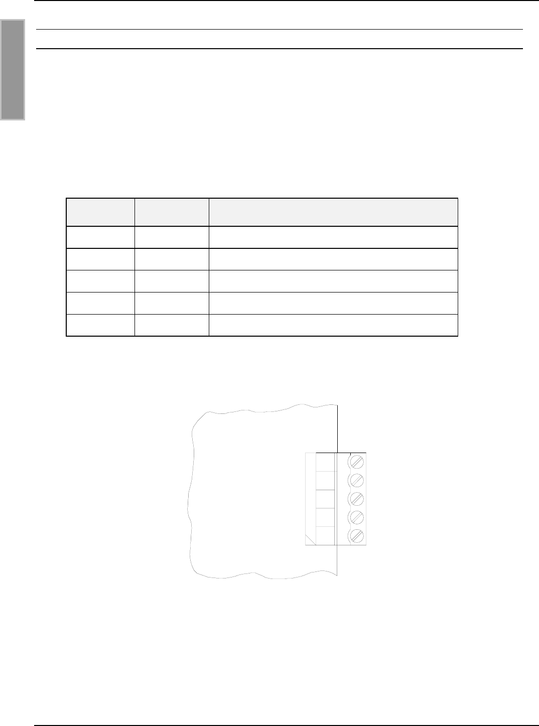
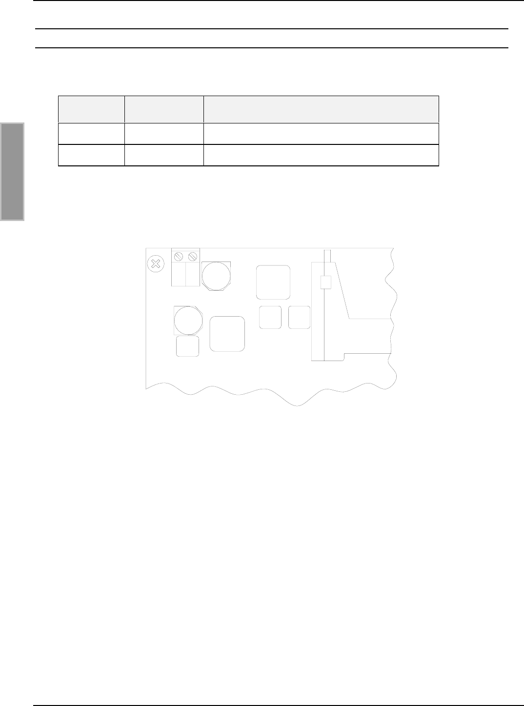
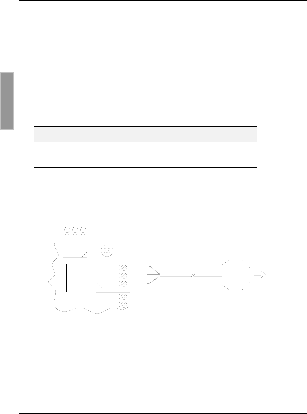
3.3 Versorgungsspannung
Die Versorgungsspannung von 24 VDC ist an der Klemme X13 anzuschließen.
Klemme Kurzzeichen Beschreibung
X13 / Pin 1 VDC Vcc – Versorgungsspannung +24 V DC
X13 / Pin 2 GND Ground – Versorgungsspannung
Tabelle 3-2: Pinbelegung Versorgungsspannung
Bild 3-4: Anschluss der Versorgungsspannung
Hinweis:
• Eine Verpolung der Versorgungsspannung kann zur Zerstörung des Gerätes führen.
• Für die Einhaltung der nationalen Vorschriften bezüglich Funkanlagen muß die Versor-
gungsspannungszuleitung mit dem beigefügten EMV-Ringkernferrit ∅ 28 mm x 20 mm
versehen werden. Hierzu ist das Kabel mindestens fünf mal, eng anliegend durch den
EMV-Ringkernferrit zu schleifen. Der Abstand zwischen Readeranschluß und Ringkern
sollte dabei maximal 10 cm betragen.
X13
GND
VDC
21
OBID i-scan®Montage ID ISC.LRM2000
FEIG ELECTRONIC GmbH Seite 12 von 55 M51001-0de-ID-B.doc
D E U T S C H
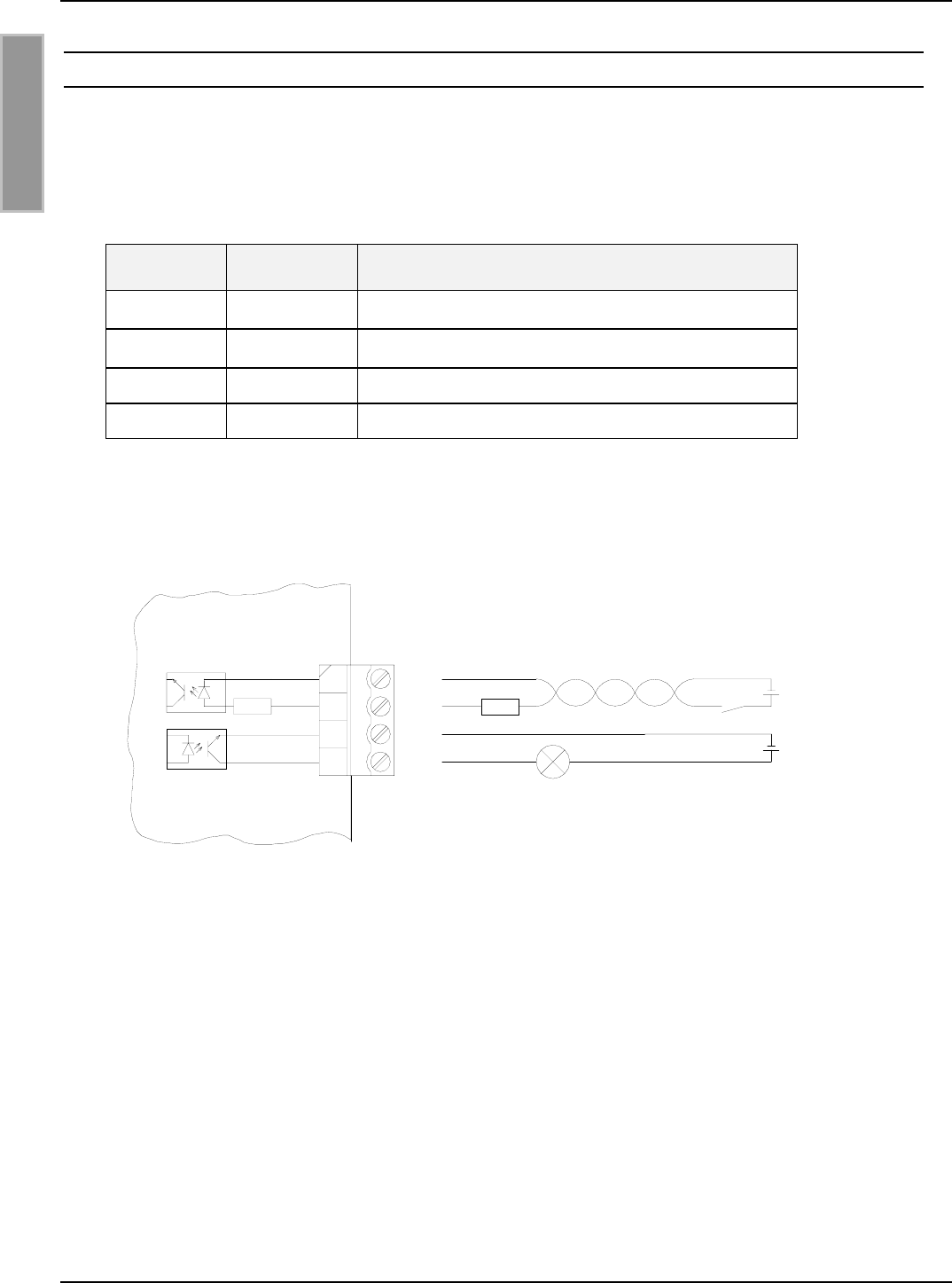
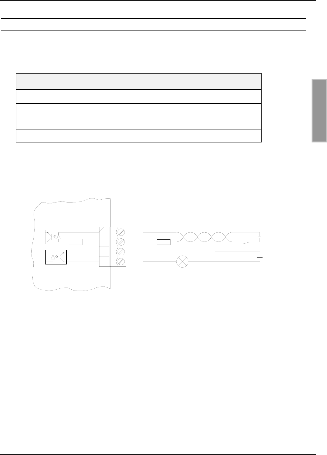
3.4 X6: Optokopplereingang und Optokopplerausgang
Die Optokoppler an Klemmleiste X6 sind galvanisch von der Reader-Elektronik getrennt und müs-
sen daher mit einer externen Spannung versorgt werden.
Klemme Kurzzeichen Beschreibung
X6 / Pin 1 O-C Kollektor – Ausgang 1
X6 / Pin 2 O-E Emitter – Ausgang 1
X6 / Pin 3 IN+ + Eingang 1
X6 / Pin 4 IN- - Eingang 1
Tabelle 3-3: Pinbelegung Optokoppler
Bild 3-5: Interne Beschaltung und mögliche externe Beschaltung der Optokoppler
Uext.
IN+
IN-
Rext
Rint
O-C
O-E Uext.
2
1
3
4
X6

OBID i-scan®Montage ID ISC.LRM2000
FEIG ELECTRONIC GmbH Seite 13 von 55 M51001-0de-ID-B.doc
D E U T S C H
3.4.1 Optokopplerausgang (X6/1-2):
Der Transistoranschluss, Kollektor und Emitter, des Optokopplerausgangs ist von der Reader-
Elektronik galvanisch getrennt und ohne interne Zusatzbeschaltung an Klemme X6 nach außen
geführt. Der Ausgang muss daher mit einer externen Spannung betrieben werden.
Hinweise:
• Der Ausgang ist für max. 24 V DC / 30 mA ausgelegt.
• Verpolung oder Überlastung des Ausgangs führt zu dessen Zerstörung.
• Der Ausgang ist nur zum Schalten ohmscher Lasten vorgesehen.
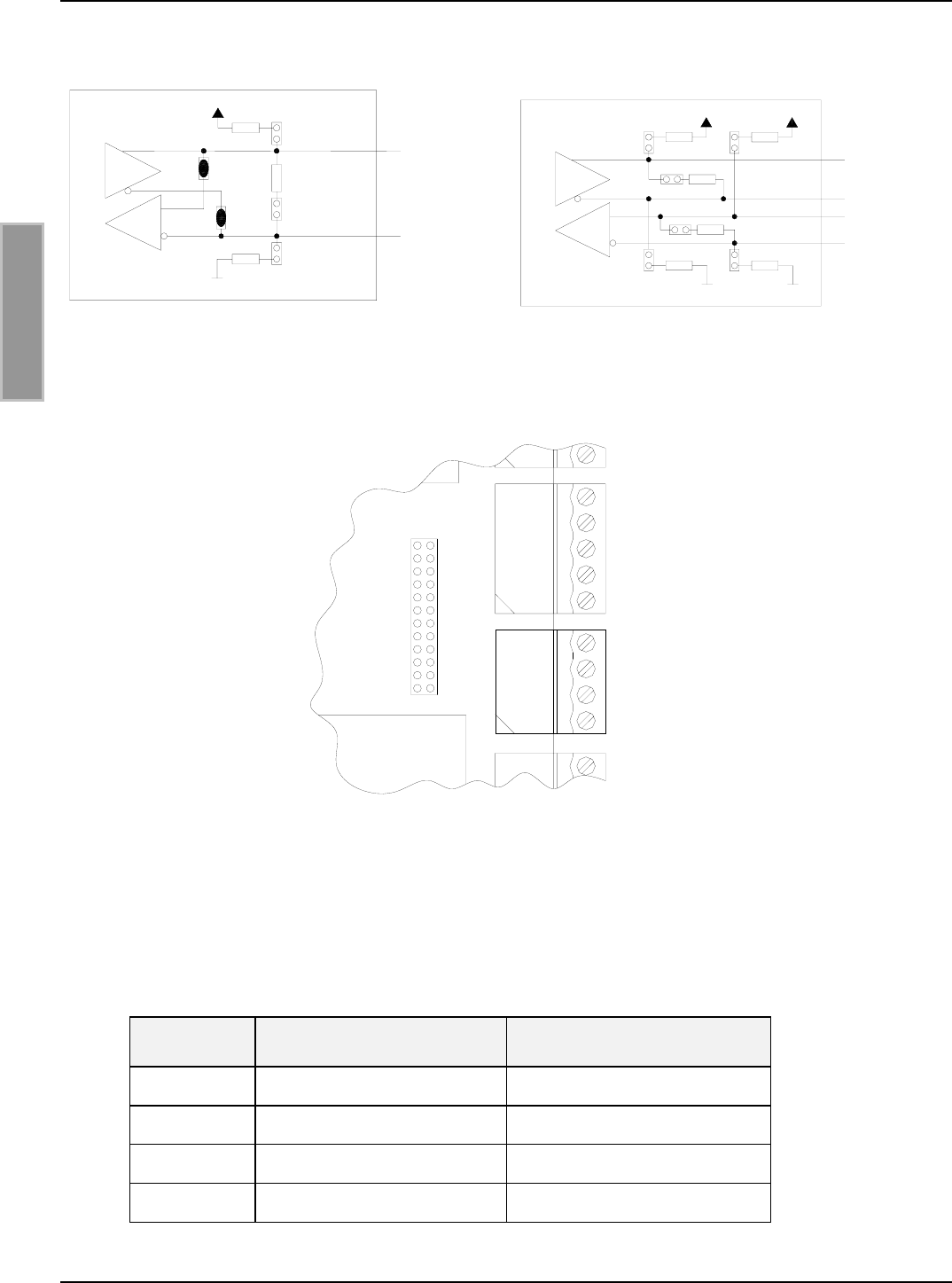
3.4.2 Optokopplereingang (X6/3-4):
Die Eingangs-LED des Optokopplers ist intern mit einem Serienwiderstand von 500 Ω beschaltet.
Bei Versorgungsspannungen größer 10V muss der Eingangsstrom durch einen weiteren externen
Vorwiderstand (siehe Tabelle 3-4) auf max. 20 mA begrenzt werden.
Tabelle 3-4 zeigt die benötigten externen Vorwiderstande bei den verschiedenen externen Span-
nungen Uext.
Externe Spannung Uext Benötigter externer
Vorwiderstand Rext
5 V ... 10 V ---
11 V ... 15 V 270 Ω
16 V ... 20 V 560 Ω
21 V ... 24 V 820 Ω
Tabelle 3-4: Benötigter externer Vorwiderstand Rext
Hinweise:
• Der Eingang ist für eine maximale Eingangsspannung von 24 V DC und einem Ein-
gangsstrom von maximal 20 mA ausgelegt.
• Verpolung oder Überlastung des Eingangs führt zu dessen Zerstörung.
OBID i-scan®Montage ID ISC.LRM2000
FEIG ELECTRONIC GmbH Seite 14 von 55 M51001-0de-ID-B.doc
D E U T S C H
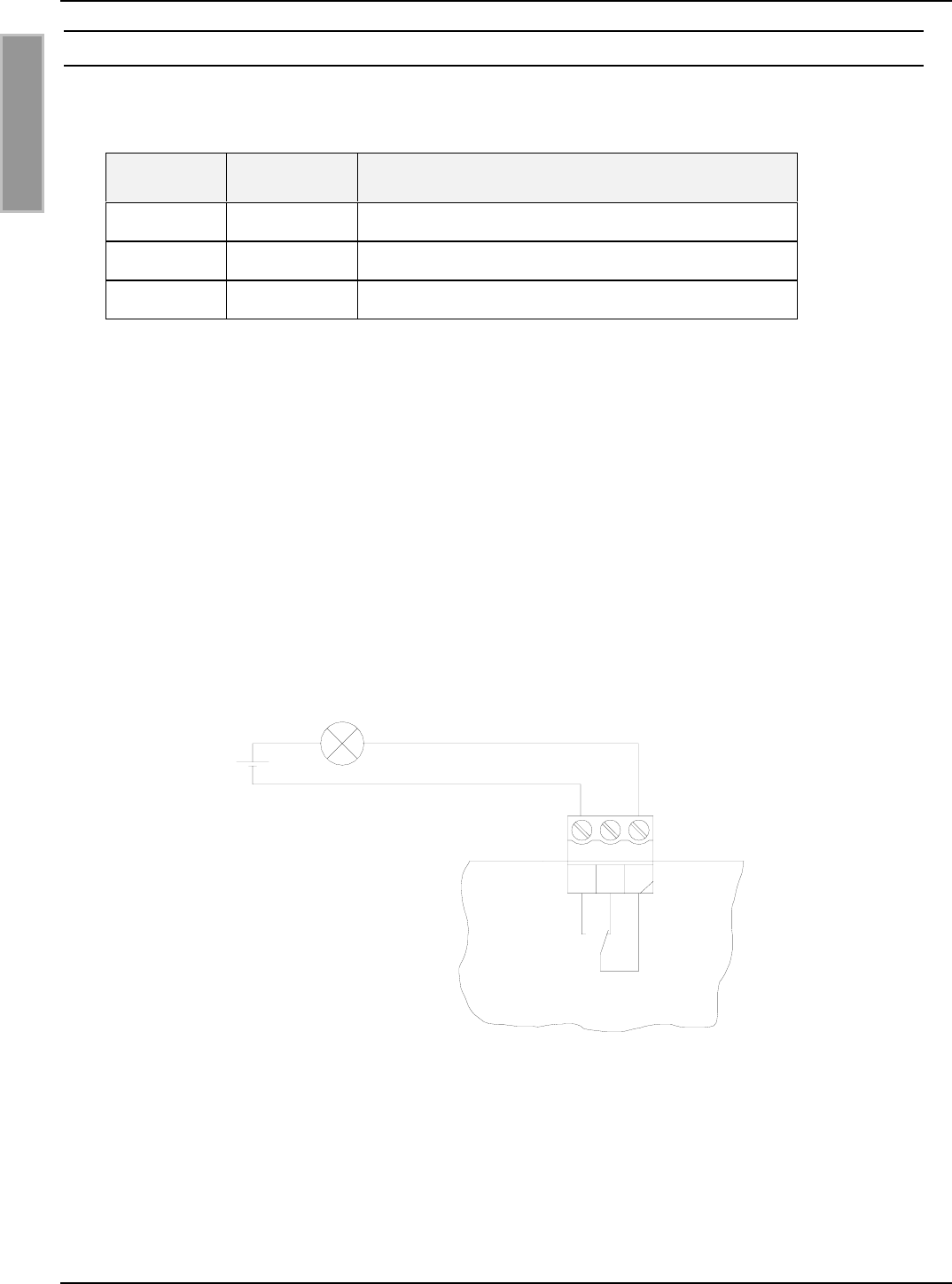
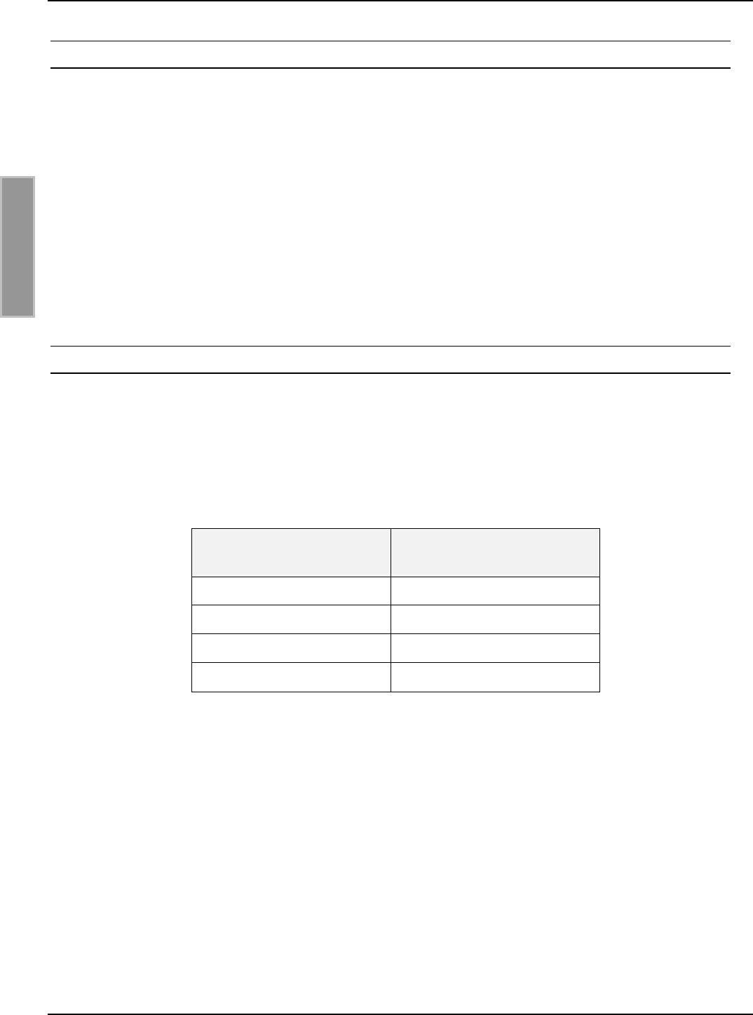
3.5 X9: Relais
Als Relaisausgang steht ein Wechsler zur Verfügung.
Klemme Kurzzeichen Beschreibung
X9 / Pin 1 COM Arbeitskontakt
X9 / Pin 2 NC Öffner
X9 / Pin 3 NO Schließer
Tabelle 3-5: Pinbelegung Relaisausgang
Hinweise:
• Der Relaisausgang ist für max. 24 V DC / 2 A ausgelegt.
• Der Relaisausgang ist nur zum Schalten ohmscher Lasten vorgesehen. Im Falle einer
induktiven Last sind die Relaiskontakte durch eine externe Schutzbeschaltung zu schüt-
zen.
Bild 3-6: Interne und mögliche externe Beschaltung des Relaisausgangs
ext.
U
12
3
X9
COM
NO
NC
OBID i-scan®Montage ID ISC.LRM2000
FEIG ELECTRONIC GmbH Seite 15 von 55 M51001-0de-ID-B.doc
D E U T S C H
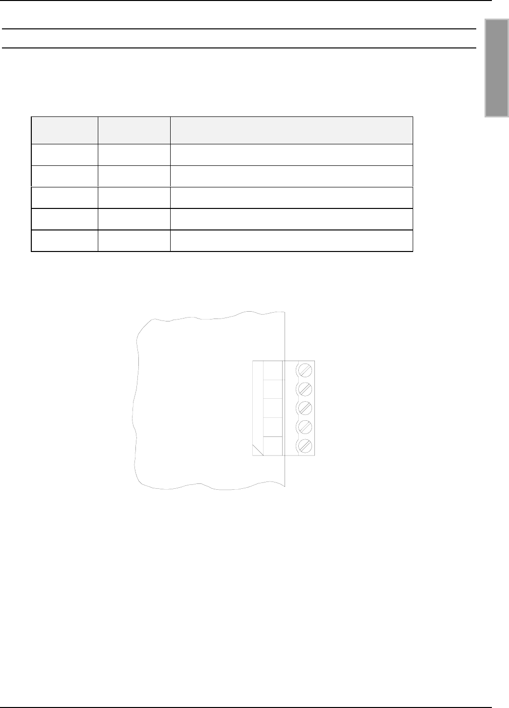
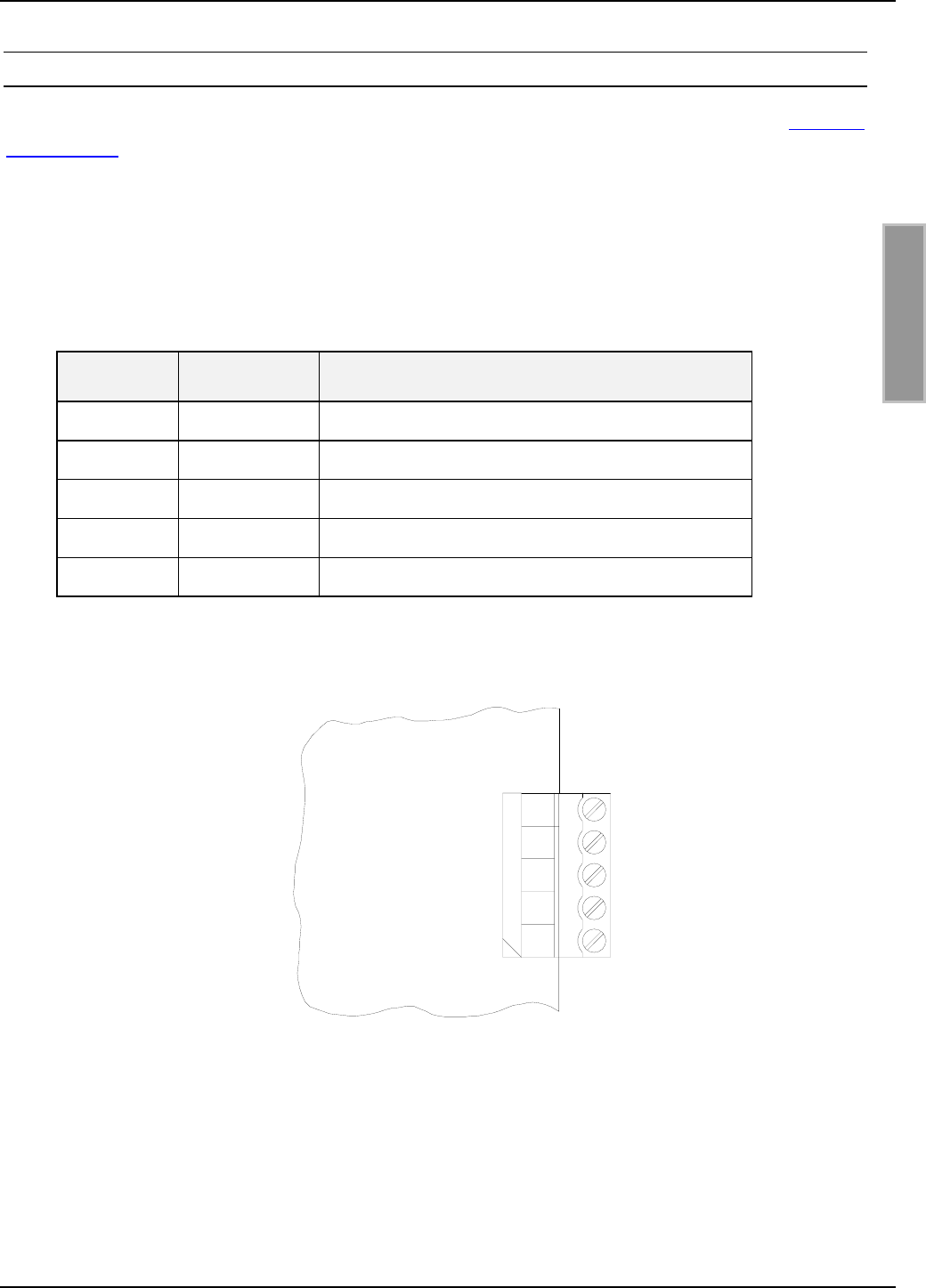
3.6 X5: Readersynchronisation
Mit der Readersynchronisation können verschiedene Aktionen der Reader synchronisiert werden.
Klemme Kurzzeichen Beschreibung
X5 / Pin 1 GND GND
X5 / Pin 2 A- - Eingang
X5 / Pin 3 B+ + Eingang
X5 / Pin 4 Y- - Ausgang
X5 / Pin 5 Z+ +Ausgang
Tabelle 3-6: Pinbelegung Readersynchronisation
Bild 3-7: Eingang und Ausgang der Synchronisation
1
2
3
4
5
OUT+ (Z+)
OUT- (Y-)
IN+ (B+)
IN- (A-)
GND
X5
OBID i-scan®Montage ID ISC.LRM2000
FEIG ELECTRONIC GmbH Seite 16 von 55 M51001-0de-ID-B.doc
D E U T S C H
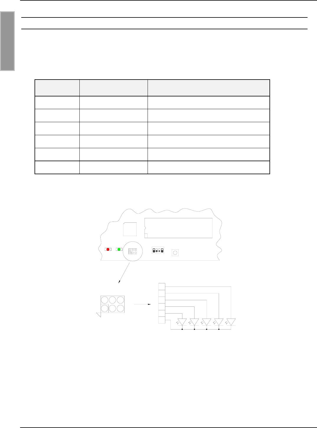
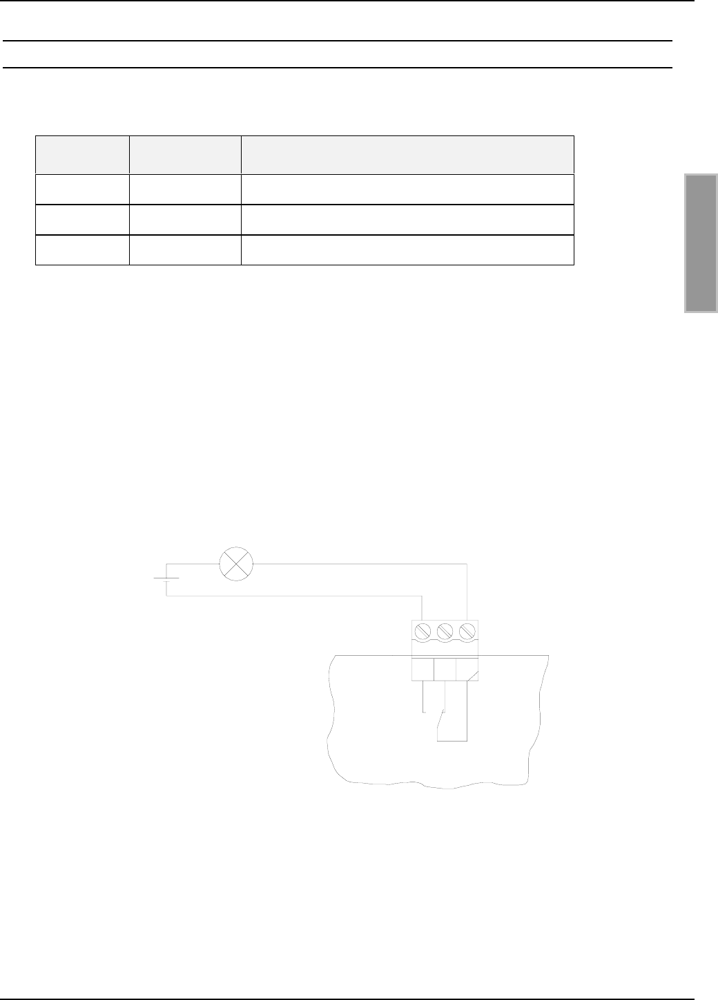
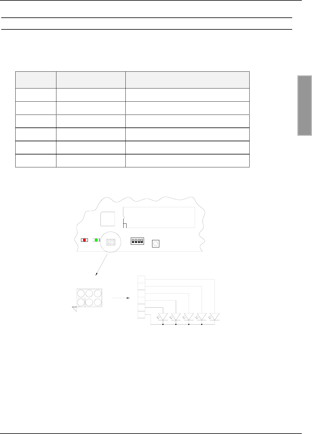
3.7 X14: Anschluss externer Diagnose-LEDs
X14 ermöglicht den Anschluss zusätzlicher externer LEDs parallel zu den internen Diagnose-
LEDs.
Der Anschluss der externen LEDs erfolgt gemäß Bild 3-8.
Klemme Kurzzeichen Beschreibung
X14 / Pin 1 V1 Anode ext. Funktion entspricht interner LED V1
X14 / Pin 2 V2 Anode ext. Funktion entspricht interner LED V2
X14 / Pin 3 V3 Anode ext. Funktion entspricht interner LED V3
X14 / Pin 4 V4 Anode ext. Funktion entspricht interner LED V4
X14 / Pin 5 V5 Anode ext. Funktion entspricht interner LED V5
X14 / Pin 6 GND Gemeinsamer GND-Anschluss
Tabelle 3-7: Pinbelegung externe LEDs
Bild 3.8: Anschluss externer LEDs an X14
Hinweis:
• Die Ausgänge an X14 sind nur zum Schalten einer externen LED vorgesehen. Überlas-
tung der Ausgänge durch andere Lasten kann zu deren Zerstörung führen.
135
6
4
2
6
5
4
3
2
1
V1V2V3
V4V5
Externe LEDs
ACC-Modul
X14
V5 V6 S1 T1
X14
X14

OBID i-scan®Montage ID ISC.LRM2000
FEIG ELECTRONIC GmbH Seite 17 von 55 M51001-0de-ID-B.doc
D E U T S C H
3.8 Schnittstellen
3.8.1 X8: RS232-Schnittstelle
Der Anschluss der RS232-Schnittstelle erfolgt über X8.
Die Übertragungsparameter können per Softwareprotokoll konfiguriert werden.
Anschlussbelegung X8 (RS232-Schnittstelle):
Klemme Kurzzeichen Beschreibung
X8 / Pin 1 GND RS232 – GND
X8 / Pin 2 RxD RS232 - RxD
X8 / Pin 3 TxD RS232 - TxD
Tabelle 3-8: Pinbelegung RS232-Schnittstelle
Bild 3-9: Verdrahtungsbeispiel für den Anschluss der RS232-Schnittstelle
PC
<
−>
<−>
<−>
X8 / 3 Pin 2
X8 / 2 Pin 3
X8 / 1 Pin 5
9-pol. D-SUB-Buchse
X8
TxD
RxD
GND
3
2
1
OBID i-scan®Montage ID ISC.LRM2000
FEIG ELECTRONIC GmbH Seite 18 von 55 M51001-0de-ID-B.doc
D E U T S C H
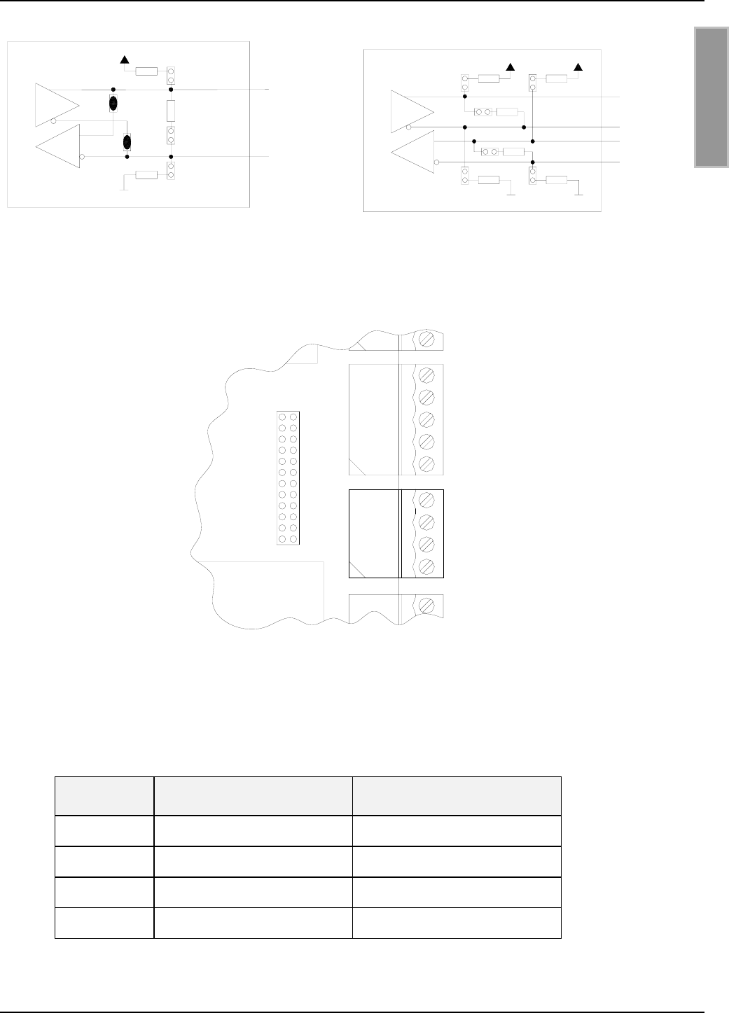
3.8.2 X7: RS485/RS422 Schnittstelle
Die zweite asynchrone Schnittstelle kann als RS485 oder RS422 konfiguriert werden (siehe Ab-
schnitt 5.1: Schnittstellenkonfiguration mittels Jumper).
Der Anschluss der RS485/RS422-Schnittstelle erfolgt über X7.
Anschlussbelegung X7 (RS485/RS422-Schnittstelle):
Klemme Kurzzeichen Beschreibung
X7 / Pin 1 GND RS485/RS422 – GND
X7 / Pin 2 A- RS485/RS422 – (A -)
X7 / Pin 3 B+ RS485/RS422 – (B +)
X7 / Pin 4 Y- RS422 – (Y -)
X7 / Pin 5 Z+ RS422 – (Z +)
Tabelle 3-9: Pinbelegung RS485/RS422-Schnittstelle
Bild 3-10: Anschlussbelegung der RS485/RS422-Schnittstelle
RS422 (Z+)
RS422 (Y-)
5
RS485/RS422 (A-)
RS485/RS422 GND
RS485/RS422 (B+)
1
2
4
3
X7

OBID i-scan®Montage ID ISC.LRM2000
FEIG ELECTRONIC GmbH Seite 19 von 55 M51001-0de-ID-B.doc
D E U T S C H
3.8.3 X11: LAN (nur Gerätevarianten mit ACC)
Der Reader verfügt über einen Integrierten 10/100Tbase Netzwerkschnittstelle mit RJ-45-
Anschluss. Der Anschluss erfolgt über X11.
Bei einer strukturierten Verkabelung sollte Kabel der Kategorie 5 verwendet werden. Dies garan-
tiert einen problemlosen Betrieb bei 10Mbps oder 100Mbps.
Anschlussbelegung X11 (Netzwerk-Schnittstelle):
Klemme Kurzzeichen Beschreibung
X11 / Pin 1 TX+ Transmit Data +
X11 / Pin 2 TX- Transmit Data -
X11 / Pin 3 RX+ Receive Data +
X11 / Pin 4 VETH+ n.c.
X11 / Pin 5 VETH+ n.c.
X11 / Pin 6 RX- Receive Data -
X11 / Pin 7 VETH- n.c.
X11 / Pin 8 VETH- n.c.
Tabelle 3-10: Pinbelegung Ethernet-Schnittstelle
3.8.4 X12: CompactFlash-Steckplatz (nur Gerätevarianten mit ACC)
Der Reader verfügt über einen CF2-Steckplatz (Stecker X12). Dieser Steckplatz ist für die Erweite-
rungsmöglichkeiten durch eine WLAN CompactFlash-Karte vorgesehen.
Nur die folgende WLAN Karte sollte benutzt werden:
WLAN CompactFlash Card Feig Order Nummer
ID ISC.CF2.WLAN-A Wireless Adapter 2421.000.01.00

OBID i-scan®Montage ID ISC.LRM2000
FEIG ELECTRONIC GmbH Seite 20 von 55 M51001-0de-ID-B.doc
D E U T S C H
4 Bedien- und Anzeigeelemente
4.1 LEDs
Tabelle 4-1 zeigt die Konfiguration der LED.
Kurzzeichen Beschreibung
LED V1 (grün) "RUN-LED 1"
- Signalisiert den ordnungsgemäßen Ablauf der
internen Reader-Software (DSP)
LED V2 (blau) Diagnose 1: RF-Kommunikation / EEPROM-Status
- Signalisiert durch ein kurzes Blinken die fehlerfreie Kommuni-
kation mit einem Transponder auf der RF-Schnittstelle
- Blinkt abwechselnd mit V1 nach dem Reset im Anschluss an
ein Software-Update
- Blinkt abwechselnd mit V1 falls nach einem Reset ein Daten-
fehler beim Lesen der Parameter auftrat
LED V3 (gelb) Diagnose 2: Host-Kommunikation
- Signalisiert durch ein kurzes Blinken das Senden eines Proto-
kolls an den Host auf der RS232/RS485-Schnittstelle
LED V4 (gelb) Reserviert
LED V5 (rot) Diagnose 4: RF-Warnung
- Leuchtet während der Reader-Initialisierung nach dem Ein-
schalten bzw. nach einem Reset.
- Leuchtet bei einem Fehler im RF-Teil des Readers. Der Feh-
lertyp kann per Software über die RS232/RS485-Schnittstelle
ausgelesen werden
LED V6 (grün) "RUN-LED 2"
- Signalisiert den ordnungsgemäßen Ablauf des
ACC-Controllers
- V6 entfällt bei Gerätevarianten ohne ACC-Controller
Tabelle 4-1: Konfiguration der LED

OBID i-scan®Montage ID ISC.LRM2000
FEIG ELECTRONIC GmbH Seite 21 von 55 M51001-0de-ID-B.doc
D E U T S C H
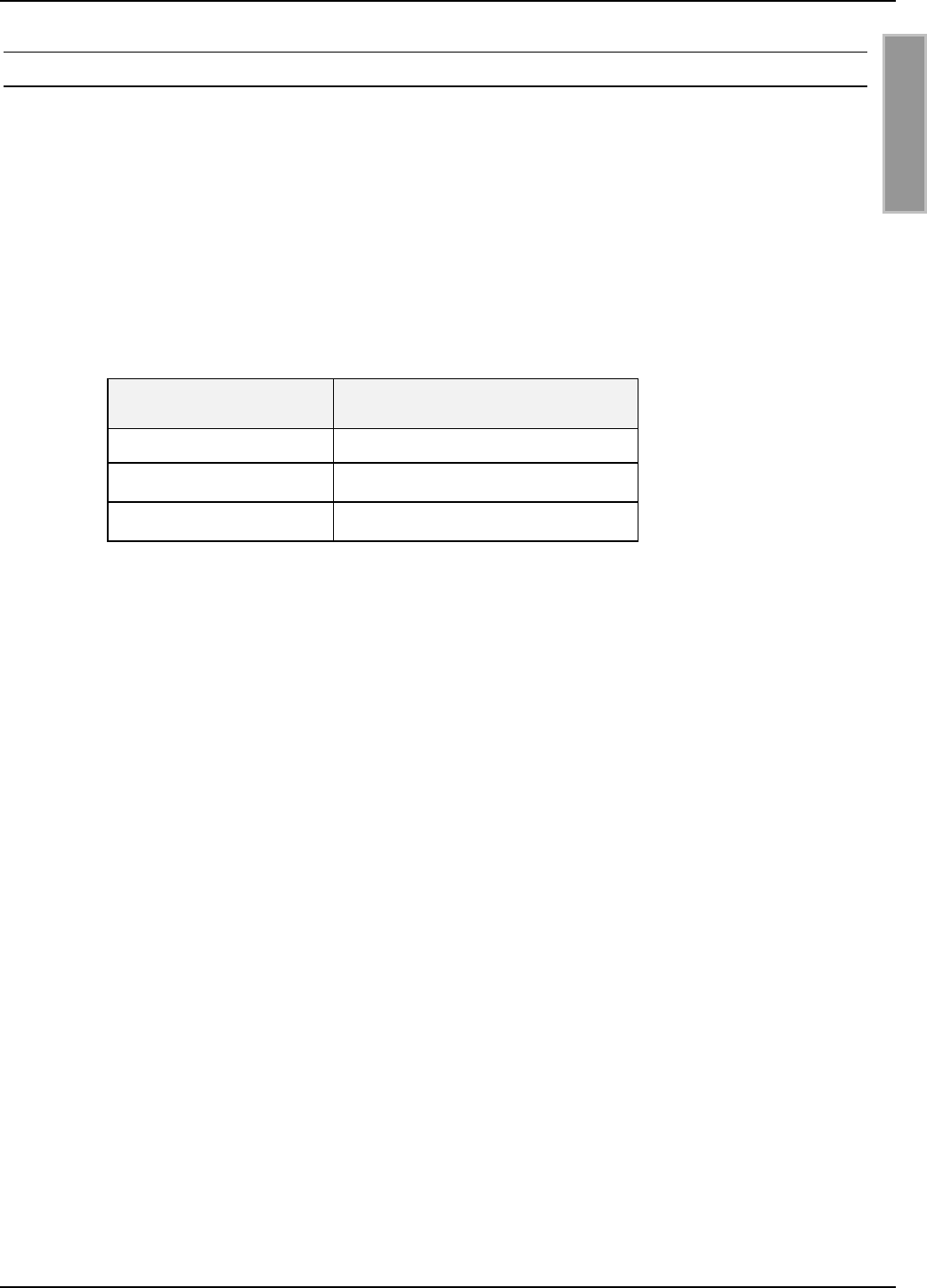
4.2 Taster / Schalter
Kurzzeichen Beschreibung
T1 Reset-Taster RF Controller
T2 Reset-Taster ACC
S1 Reserviert
Tabelle 4-2: Taster und Schalter
- T1: Durch betätigen von T1 wird am RF-Controller ein Reset durchgeführt
- T2: Durch betätigen von T2 wird am ACC ein Reset durchgeführt

OBID i-scan®Montage ID ISC.LRM2000
FEIG ELECTRONIC GmbH Seite 22 von 55 M51001-0de-ID-B.doc
D E U T S C H
5 Inbetriebnahme
5.1 Schnittstellenkonfiguration
5.1.1 RS485/RS422
Über die Jumper J7 – J8 kann die asynchrone Schnittstelle als RS485- oder RS422-Schnittstelle
konfiguriert werden.
Jumper RS485 RS422
J7 Geschlossen offen
J8 Geschlossen offen
Tabelle 5-1: Konfiguration der RS485/RS422-Schnitstelle
Es können die eventuell benötigten Abschlusswiderstände mit den Jumpern J1 bis J6 zugeschaltet
werden.
Jumper Geschlossen offen
J1 Pull-Up an RS4xx - B ohne Pull-Up an RS4xx - B
J2 Pull-Down an RS4xx - A ohne Pull-Down an RS4xx – A
J5 Abschlusswiderstand
RS4xx - A ⇔ RS4xx - B
ohne Abschlusswiderstand
RS485 - A ⇔ RS485 - B
J3 Pull-Up an RS422 - Z ohne Pull-Up an RS422 - Z
J4 Pull-Down an RS422 - Y ohne Pull-Down an RS422 – Y
J6 Abschlusswiderstand
RS422 - Y ⇔ RS422 - Z
ohne Abschlusswiderstand
RS422 - Y ⇔ RS422 - Z
Tabelle 5-2: Abschlusswiderstände der RS485/RS422
OBID i-scan®Montage ID ISC.LRM2000
FEIG ELECTRONIC GmbH Seite 23 von 55 M51001-0de-ID-B.doc
D E U T S C H
RS485 +
J1
J5
J2
500 Ohm
500 Ohm
120 Ohm
J7
J8
RS485 -
RS422 Y-
RS422 B+
500
500 500
120
120
J2
J3 J1
J6
J5
RS422 Z+
J4 500
RS422 A-
Bild 5-1: Jumper der RS485-Schnittstelle Bild 5-2: Jumper der RS422-Schnittstelle
Bild 5-3: Jumper der RS485/RS422-Schnittstelle
Tabelle 5-3 zeigt die Standardkonfiguration der Jumper J9 bis J12. Diese sind für die RS485 und
RS422 identisch.
Jumper ID ISC.LRM2000-A ID ISC.LRM2000-B
J9 geschlossen offen
J10 geschlossen geschlossen
J11 offen offen
J12 offen geschlossen
Tabelle 5-3: Standardkonfiguration der RS485/RS422
J12
J11
J10
J9
J8
J7
J6
J5
J4
J3
J2
J1 X6
X7

OBID i-scan®Montage ID ISC.LRM2000
FEIG ELECTRONIC GmbH Seite 24 von 55 M51001-0de-ID-B.doc
D E U T S C H
5.1.1.1 Adresseinstellung RS485/RS422x für Busbetrieb
Für den Busbetrieb bietet der Reader die Möglichkeit die benötigte Busadresse per Software zu
vergeben.
Die Adressvergabe erfolgt über den Host-Rechner. Mit Hilfe der Software können dem Reader die
Adressen "0" bis "254" zugewiesen werden.
Hinweis:
Da alle Reader werksseitig auf die Adresse 0 eingestellt sind, müssen sie nacheinander an-
geschlossen und konfiguriert werden.
5.1.2 Netzwerkanschluss - LAN
Vorraussetzung für den Einsatz des TCP/IP-Protokolls ist, dass jedes Gerät am Netzwerk über
eine eigene IP-Adresse verfügt. Alle Reader verfügen über eine werksseitig voreingestellte IP-
Adresse.
Die Reader müssen nacheinander ans Netzwerk angeschlossen und konfiguriert werden.
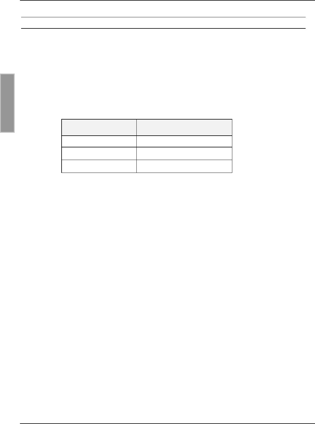
Tabelle 5-4 zeigt die Standardkonfiguration des Netzwerkanschlusses.
Netzwerk Adresse
IP-Adresse 192.168.10.10
Subnet-Mask 255.255.255.0
Port 10001
Tabelle 5-4: Standardkonfiguration des Netzwerkanschlusses
OBID i-scan®Montage ID ISC.LRM2000
FEIG ELECTRONIC GmbH Seite 25 von 55 M51001-0de-ID-B.doc
D E U T S C H
5.1.3 Netzwerkanschluss - WLAN
Vorraussetzung für den Einsatz des TCP/IP-Protokolls ist, dass jedes Gerät am Netzwerk über
eine eigene IP-Adresse verfügt. Alle Reader verfügen über eine werksseitig voreingestellte IP-
Adresse für das WLAN.
Die Reader müssen nacheinander ans Netzwerk angeschlossen und konfiguriert werden.
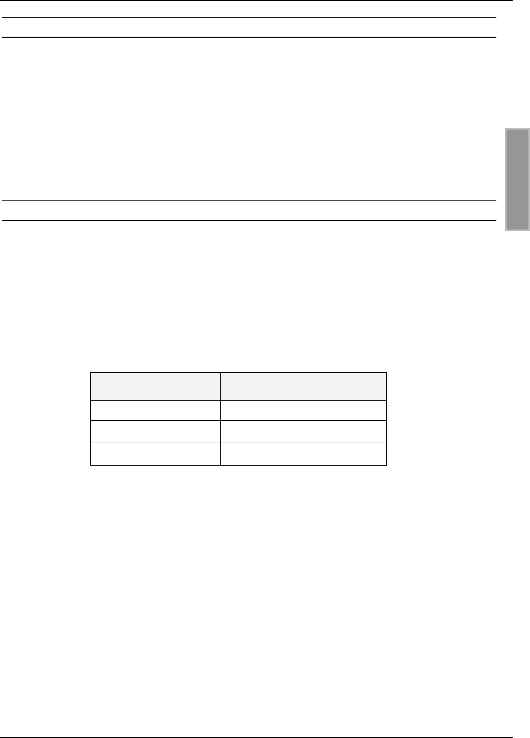
Tabelle 5-5 zeigt die Standardkonfiguration des WLAN Netzwerkanschlusses.
Netzwerk Adresse
IP-Adresse 192.168.10.11
Subnet-Mask 255.255.255.0
Port 10002
Tabelle 5-5: Standardkonfiguration des WLAN Netzwerkanschlusses

OBID i-scan®Montage ID ISC.LRM2000
FEIG ELECTRONIC GmbH Seite 26 von 55 M51001-0de-ID-B.doc
D E U T S C H
6 Funkzulassungen
6.1 Europa (CE)
Die Funkanlage entspricht, bei bestimmungsgemäßer Verwendung den grundlegenden Anforde-
rungen des Artikels 3 und den übrigen einschlägigen Bestimmungen der R&TTE Richtlinie
1999/5/EG vom März 99.
Einschränkungen für den Betrieb des ID ISC.LRM2000 (Stand: Oktober 2005):
Für den Betrieb des ID ISC.LRM2000 mit einer maximalen Feldstärke von 42 dBµA/m in 10 m
Entfernung (ERC/REC 70-03 Annex 9 Band F) gelten folgende Einschränkungen:
Betrieb derzeit nicht gestattet : TUR
Betrieb nur mit individueller Lizenz : HRV
Für den Betrieb des ID ISC.LRM2000 mit einer maximalen Feldstärke von 60 dBµA/m in 10 m
Entfernung (ERC/REC 70-03 Annex 9 Band F1) gelten folgende Einschränkungen:
Betrieb derzeit nicht gestattet : AUT, BEL, E, F, GRC, IRL, LIE, LUX, NOR,
POR, EST, LVA, POL, SVK, HRV, ROU,
SUI, CYP, LTU, BUL, TUR
6.2 USA (FCC)
FCC ID: PJMLRM2000
This device complies with Part 15 of the FCC Rules. Operation is subject to the following
two conditions:
(1) this device may not cause harmful interference, and
(2) this device must accept any interference received, including interference that may
cause undesired operation.
Unauthorized modifications may void the authority granted under Federal communica-
tions Commission Rules permitting the operation of this device.
Warning: Changes or modification made to this equipment not expressly approved by
FEIG ELECTRONIC GmbH may void the FCC authorization to operate this equipment.

OBID i-scan®Montage ID ISC.LRM2000
FEIG ELECTRONIC GmbH Seite 27 von 55 M51001-0de-ID-B.doc
D E U T S C H
7 Technische Daten
ID ISC.LRM2000-A ID ISC.LRM2000-B
Mechanische Daten
• Abmessungen ( B x H x T ) 160 mm x 120 mm x 46 mm
• Gewicht ca. 0,6 kg
Elektrische Daten
• Spannungsversorgung 24 V DC ± 15 %
Noise Ripple : max. 150 mV
• Leistungsaufnahme max. 32 VA
• Betriebsfrequenz 13,56 MHz
• Sendeleistung 4W – 12 W
(per Software in 250 mW Schritten einstellbar)
• Modulationsgrad 10% - 30% und 100%
(per Software einstellbar)
• Antennenanschluss SMA Buchse (50Ω)
• DC Spannung auf Antennen-
leitung
8 V DC (max. 150mA)
• Diagnoseoptionen internes VSWR-Meter
interne Temperaturüberwachung
• Ausgänge:
– 1 Optokoppler
– 1 Differenzausgang
– 1 Relais ( 1 x Wechsler)
24 V DC / 30 mA
Reader Synchronisation
24 V DC / 2 A
• Eingänge
– 1 Optokoppler
– 1 Differenzeingang
max. 24 V DC/ 20 mA
Reader Synchronisation
• Schnittstellen - RS232
- RS484 / RS422
- Ethernet (TCP/IP)
- Compact Flash II
(WLAN)
- RS232
- RS484 / RS422

OBID i-scan®Montage ID ISC.LRM2000
FEIG ELECTRONIC GmbH Seite 28 von 55 M51001-0de-ID-B.doc
D E U T S C H
• Protokoll Modi - FEIG ISO HOST
- BRM
(Datenfilterung und
Datenpufferung
- FEIG ISO HOST
• Unterstützte Transponder - I-Code 1
- ISO 15693, ISO 18000-3-A
z. B. I-Code SLI, my-d, STM LRI512/64, Tag-it HFI
• Signalgeber, optisch 6 LEDs zur Diagnose
des Betriebszustandes
5 LEDs zur Diagnose
des Betriebszustandes
Umgebungsbedingungen
• Temperaturbereich
– Betrieb
– Lagerung
-20°C bis +55°C
–25°C bis +85°C
• Luftfeuchtigkeit 5% - 80%, nicht kondensierend
• Vibration EN60068-2-6
10 Hz bis 150 Hz : 0,075 mm / 1 g
• Schock EN60068-2-27
Beschleunigung : 30 g
Zulassung
• Zulassung Funk
– Europa
– USA
EN 300 330
FCC 47 CFR Part 15
• EMV EN 301 489
• Sicherheit
– Elektrische Sicherheit
– Human Exposure
EN 60950
EN 50364

OBID i-scan®Installation ID ISC.LRM2000
FEIG ELECTRONIC GmbH Page 30 of 55 M51001-0de-ID-B.doc
E N G L I S H
Note
© Copyright 2005 by
FEIG ELECTRONIC GmbH
Lange Strasse 4
D-35781 Weilburg-Waldhausen
Tel.: +49 6471 3109-0
http://www.feig.de
With the edition of this document, all previous editions become void. Indications made in this manual may be
changed without previous notice.
Copying of this document, and giving it to others and the use or communication of the contents thereof are
forbidden without express authority. Offenders are liable to the payment of damages. All rights are reserved
in the event of the grant of a patent or the registration of a utility model or design.
Composition of the information in this manual has been done to the best of our knowledge. FEIG
ELECTRONIC GmbH does not guarantee the correctness and completeness of the details given in this
manual and may not be held liable for damages ensuing from incorrect or incomplete information. Since,
despite all our efforts, errors may not be completely avoided, we are always grateful for your useful tips.
The installation instructions given in this manual are based on advantageous boundary conditions. FEIG
ELECTRONIC GmbH does not give any guarantee promise for perfect function in cross environments.
FEIG ELECTRONIC GmbH assumes no responsibility for the use of any information contained in this
manual and makes no representation that they free of patent infringement. FEIG ELECTRONIC GmbH does
not convey any license under its patent rights nor the rights of others.
OBID® and OBID i-scan® are registered trademarks of FEIG ELECTRONIC GmbH.
I-CODE® is a registered trademark of Philips Electronics N.V.
Tag-itTM is a registered trademark of Texas Instruments Incorporated.

OBID i-scan®Installation ID ISC.LRM2000
FEIG ELECTRONIC GmbH Page 31 of 55 M51001-0de-ID-B.doc
E N G L I S H
Contents
1 Safety Instructions / Warning - Read before start-up ! 33
2 Performance Features of Reader Family ID ISC.LRM2000 34
2.1 Performance Features.................................................................................................34
2.2 Available Reader Types ..............................................................................................34
3 Installation and mounting 35
3.1 Terminals .....................................................................................................................36
3.2 Antenna connection....................................................................................................37
3.3 Supply voltage.............................................................................................................38
3.4 X6: Optocouplers.........................................................................................................39
3.4.1 Optocoupler output (X6/1-2):.........................................................................................40
3.4.2 Optocoupler input (X6/3-4):...........................................................................................40
3.5 X9: Relay ......................................................................................................................41
3.6 X5: Reader synchronization .......................................................................................42
3.7 X14: External diagnostic LED connections ..............................................................43
3.8 Interfaces .....................................................................................................................44
3.8.1 X8: RS232 interface ......................................................................................................44
3.8.2 X7: RS485/RS422 interface ..........................................................................................45
3.8.3 X11: LAN (only device version with ACC) ..................................................................46
3.8.4 X12: CompactFlash Slot (only device version with ACC)...........................................46
4 Operating and Display Elements 47
4.1 LEDs .............................................................................................................................47
4.2 Buttons / Switches ......................................................................................................48
5Startup 49
5.1 Interface configuration................................................................................................49
5.1.1 RS485/RS422 ...............................................................................................................49

OBID i-scan®Installation ID ISC.LRM2000
FEIG ELECTRONIC GmbH Page 32 of 55 M51001-0de-ID-B.doc
E N G L I S H
5.1.2 Network connection - LAN.............................................................................................51
5.1.3 Network connection - WLAN .........................................................................................52
6 Radio Approvals 53
6.1 Europe (CE)..................................................................................................................53
7 Technical Data 54

OBID i-scan®Installation ID ISC.LRM2000
FEIG ELECTRONIC GmbH Page 33 of 55 M51001-0de-ID-B.doc
E N G L I S H
1 Safety Instructions / Warning - Read before start-up !
• The device may only be used for the intended purpose designed by for the manufacturer.
• The operation manual should be conveniently kept available at all times for each user.
• Unauthorized changes and the use of spare parts and additional devices which have not been
sold or recommended by the manufacturer may cause fire, electric shocks or injuries. Such
unauthorized measures shall exclude any liability by the manufacturer.
• The liability-prescriptions of the manufacturer in the issue valid at the time of purchase are valid
for the device. The manufacturer shall not be held legally responsible for inaccuracies, errors,
or omissions in the manual or automatically set parameters for a device or for an incorrect
application of a device.
• Repairs may only be executed by the manufacturer.
• Installation, operation, and maintenance procedures should only be carried out by qualified
personnel.
• Use of the device and its installation must be in accordance with national legal requirements
and local electrical codes .
• When working on devices the valid safety regulations must be observed.
• Special advice for carriers of cardiac pacemakers:
Although this device doesn't exceed the valid limits for electromagnetic fields you should keep
a minimum distance of 25 cm between the device and your cardiac pacemaker and not stay in
an immediate proximity of the device respective the antenna for some time.

OBID i-scan®Installation ID ISC.LRM2000
FEIG ELECTRONIC GmbH Page 34 of 55 M51001-0de-ID-B.doc
E N G L I S H
2 Performance Features of Reader Family ID ISC.LRM2000
2.1 Performance Features
The Reader has been developed for reading passive data carriers, so-called „Smart Labels“, using
an operating frequency of 13.56 MHz.
2.2 Available Reader Types
The following Readers are currently available:
Reader type Description
ID ISC.LRM2000-A Device version with ACC
ID ISC.LRM2000-B Device version without ACC
Table 2-1: Reader types
Reader type Description
ID ISC.LR2000-A Device version with ACC and Plastic Enclosure
Table 2-2: Reader types
OBID i-scan®Installation ID ISC.LRM2000
FEIG ELECTRONIC GmbH Page 35 of 55 M51001-0de-ID-B.doc
E N G L I S H
3 Installation and mounting
The Reader Module is designed for installation on a heat sink. Mounting is accomplished using the
∅ 4.5 mm holes located in each corner of the base plate (see Fig. 3-1).
Fig. 3-1: Reader with mounting plate
V1
GND
VDC
Z +
Y -
B +
A -
GND
V5V3V2 V4 V6 X14 T1
S1 T2
Öffner
Schließer
Wechsler
J12
J11
J10
J9
J8
J7
J6
J5
J4
J3
J2
J1
J20
ACC-Modul
X12
X11
X9
Z +
Y -
B +
A -
GND
IN -
IN +
OUT-E
OUT-C
X5
X6
TxD
RxD
GND
X7
X8
X13
* * *
OBID i-scan®Installation ID ISC.LRM2000
FEIG ELECTRONIC GmbH Page 36 of 55 M51001-0de-ID-B.doc
E N G L I S H
To fully exploit the performance of the Reader Module, the heat sink should have a thermal resis-
tance RThK of max. 1 K/W. When attaching the Reader Module to the heat sink you should strive for
a little heat transfer resistance between the base plate and the heat sink as possible. The use of
heat sink compound is recommended.
If the antenna is properly tuned and there is sufficient air convection along the mounting plate, the
ID ISC.LRM2000 can be operated without an additional heat sink at up to 2W of power. Note here
however that detuning of the antenna can result in additional heating of the Reader. In such cases
the Reader regulates its output power down until the upper temperature limit of its final stage is
reached again.
3.1 Terminals
Figure 3-2 shows the terminals and control elements of the ID ISC.LRM2000
Fig. 3-2: Reader terminals
V1 V2 V3 V4 V5 V6
T1 T2
S1
X14
J20
X12
X13 X11
X9
J12
J11
J10
J9
J8
J7
J6
J5
J4
J3
J2
J1
X8
X7
X6
X5
ACC-Modul
ANT1
OBID i-scan®Installation ID ISC.LRM2000
FEIG ELECTRONIC GmbH Page 37 of 55 M51001-0de-ID-B.doc
E N G L I S H
3.2 Antenna connection
The SMA socket „ANT1“is located on the lower circuit board for connecting the antenna to the ID
ISC.LRM2000.
Active external function units (e.g. ID ISC.DAT) can also be supplied with 8 V DC through the an-
tenna terminal. The maximum current draw is then not allowed to exceed 150mA.
The maximum tightening torque for the SMA socket is 0.45 Nm.
Attention:
Greater tightening torque will destroy the socket.
Terminal Description
ANT1 For connecting the antenna
Table 3-1: Antenna jack
• The standing wave ratio VSWR for the antenna should not exceed a value of 1.2.
• The optimum operating Q factor of the antenna should be in a range of Qoper = 10...30. To
determine the operating Q the antenna must be supplied with a 50 Ohm source such as
a network analyzer or frequency generator.
• To prevent external coupled noise, the antenna cable should be fitted with the included
EMC ferrite ring core ∅ 28 mm x 20 mm. The antenna line must be wound around the
ring core for at least 4 turns. The distance between the Reader termination and the ring
core should be maximum 10 cm (see Fig. 3-3).
• When connecting an antenna, ensure that it does not exceed the permissible limits pre-
scribed by the national regulations for radio frequency devices.
Fig. 3-3: Antenna line with EMC ring cores
OBID i-scan®Installation ID ISC.LRM2000
FEIG ELECTRONIC GmbH Page 38 of 55 M51001-0de-ID-B.doc
E N G L I S H
3.3 Supply voltage
The supply voltage of 24 VDC is connected to Terminal X13.
Terminal Abbreviation Description
X13 / Pin 1 VDC Vcc – supply voltage + 24 VDC
X13 / Pin 2 GND Ground – supply voltage
Table 3-2: Pinouts for supply voltage
Fig. 3-4: Connecting the supply voltage
Note:
• Reversing the supply voltage polarity may destroy the device.
• To meet national requirements for radio frequency devices the power supply line must
be fitted with one of the supplied EMC ring cores ∅ 28 mm x 20 mm. The power supply
line must be wound around the ring core for at least 5 turns. The distance between the
Reader termination and the ring core should be maximum 10 cm.
X13
GND
VDC
21
OBID i-scan®Installation ID ISC.LRM2000
FEIG ELECTRONIC GmbH Page 39 of 55 M51001-0de-ID-B.doc
E N G L I S H
3.4 X6: Optocouplers
The optocouplers on Terminal X6 are galvanically isolated from the Reader electronics and must
therefore be externally supplied.
Terminal Abbreviation Description
X6 / Pin 1 O-C Collector – Output 1
X6 / Pin 2 O-E Emitter – Output 1
X6 / Pin 3 IN+ + Input 1
X6 / Pin 4 IN- - Input 1
Table 3-3: Optocoupler pin-outs
Fig. 3-5: Internal and possible external wiring of the optocouplers
Uext.
IN+
IN-
Rext
Rint
O-C
O-E Uext.
2
1
3
4
X6
OBID i-scan®Installation ID ISC.LRM2000
FEIG ELECTRONIC GmbH Page 40 of 55 M51001-0de-ID-B.doc
E N G L I S H
3.4.1 Optocoupler output (X6/1-2):
The transistor connections, collector and emitter, of the optocoupler output are galvanically isolated
from the Reader electronics and are carried to the outside without any internal ancillary circuitry on
Terminal X6. The output must therefore be powered by an external power supply.
Note:
• The output is configured for max. 24 V DC / 30 mA.
• Polarity reversal or overload on the output will destroy it.
• The output is intended for switching resistive loads only.
3.4.2 Optocoupler input (X6/3-4):
The input LED associated with the optocoupler is connected internally to a series resistor of 500 Ω.
For supply voltages of greater than 10V the input current must be limited to max. 20 mA by means
of an additional series resistor (see Table 3-4).
Table 3-4 shows the necessary external resistors for various external voltages Uext.
External voltage Uext Required external series
resistor Rext
5 V ... 10 V ---
11 V ... 15 V 270 Ω
16 V ... 20 V 560 Ω
21 V ... 24 V 820 Ω
Table 3-4: Required external series resistor Rext
Notes:
• The input is configured for a maximum input voltage of 24 V DC and an input current of
max. 20 mA.
• Polarity reversal or overload on the input will destroy it.
OBID i-scan®Installation ID ISC.LRM2000
FEIG ELECTRONIC GmbH Page 41 of 55 M51001-0de-ID-B.doc
E N G L I S H
3.5 X9: Relay
A relay output is provided in the form of a changeover relay.
Terminal Abbreviation Description
X9 / Pin 1 COM Working contact
X9 / Pin 2 NC Normally closed
X9 / Pin 3 NO Normally open
Table 3-5: Relay output pin-outs
Notes:
• The relay output is configured for max. 24 V DC / 2 A.
• The relay output is intended for switching resistive loads only. If an inductive load is
connected, the relay contacts must be protected by means of an external protection
circuit.
Fig. 3-6: Internal and possible external wiring of the relay output
ext.
U
12
3
X9
COM
NO
NC
OBID i-scan®Installation ID ISC.LRM2000
FEIG ELECTRONIC GmbH Page 42 of 55 M51001-0de-ID-B.doc
E N G L I S H
3.6 X5: Reader synchronization
Reader synchronization can be used to synchronize various Reader actions.
Terminal Abbreviation Description
X5 / Pin 1 GND GND
X5 / Pin 2 A- - Input
X5 / Pin 3 B+ + Input
X5 / Pin 4 Y- - Output
X5 / Pin 5 Z+ + Output
Table 3-6: Reader synchronization pin-outs
Fig. 3-7: Synchronization input and output
1
2
3
4
5
OUT+ (Z+)
OUT- (Y-)
IN+ (B+)
IN- (A-)
GND
X5
OBID i-scan®Installation ID ISC.LRM2000
FEIG ELECTRONIC GmbH Page 43 of 55 M51001-0de-ID-B.doc
E N G L I S H
3.7 X14: External diagnostic LED connections
X14 allows for connection of additional external LEDs in parallel with the internal diagnostic LEDs.
The external LEDs are connected as shown in Fig. 3.8.
Terminal Abbreviation Description
1V1 Anode ext. Function same as internal LED V1
2V2 Anode ext. Function same as internal LED V2
3V3 Anode ext. Function same as internal LED V3
4V4 Anode ext. Function same as internal LED V4
5V5 Anode ext. Function same as internal LED V5
6GND Common GND
Table 3-7 External LED pin-outs
Fig. 3.8: Connecting external LEDs to X14
Note:
• The outputs on X14 are intended for switching an external LED only. Overloading the
outputs with other loads may destroy them.
external LEDs
V5
6
4
5V4 V3 V2 V1
1
2
3
X14
31 5
4
X14
26
V5 V6 X14 S1 T1
ACC-Modul
OBID i-scan®Installation ID ISC.LRM2000
FEIG ELECTRONIC GmbH Page 44 of 55 M51001-0de-ID-B.doc
E N G L I S H
3.8 Interfaces
3.8.1 X8: RS232 interface
The RS232 interface is connected on X8.
The transmission parameters can be configured by means of software protocol.
Pin configuration X8 (RS232 interface):
Terminal Abbreviation Description
1GND RS232 – GND
2RxD RS232 - RxD
3TxD RS232 - TxD
Table 3-8: RS232 interface pin-outs
Fig. 3-9: Wiring example for connecting the RS232 interface
X8 / 3
X8 / 2
X8 / 1
Pin 2
<−>
Pin 5
Pin 3
<−>
<−>
9-pol. D-SUB-Jack
1
2
3
X8
TxD
RxD
GND PC
OBID i-scan®Installation ID ISC.LRM2000
FEIG ELECTRONIC GmbH Page 45 of 55 M51001-0de-ID-B.doc
E N G L I S H
3.8.2 X7: RS485/RS422 interface
The second asynchronous interface can be configured for RS485 or RS422 (see Section Interface
configuration).
The RS485/RS422 interface is connected on X7.
Pin configuration X7 (RS485/RS422 interface):
Terminal Abbreviation Description
X7 / Pin 1 GND RS485/RS422 – GND
X7 / Pin 2 A- RS485/RS422 – (A -)
X7 / Pin 3 B+ RS485/RS422 – (B +)
X7 / Pin 4 Y- RS422 – (Y -)
X7 / Pin 5 Z+ RS422 – (Z +)
Table 3-9: RS485/RS422 interface pin-outs
Fig. 3-10: Wiring example for the RS485/RS422 interface
RS422 (Z+)
RS422 (Y-)
5
RS485/RS422 (A-)
RS485/RS422 GND
RS485/RS422 (B+)
1
2
4
3
X7
OBID i-scan®Installation ID ISC.LRM2000
FEIG ELECTRONIC GmbH Page 46 of 55 M51001-0de-ID-B.doc
E N G L I S H
3.8.3 X11: LAN (only device version with ACC)
The Reader has an integrated 10/100Tbase network port for an RJ45. Connection is made on X11.
With structured cabling Cat 5 cables should be used. This ensure reliable operation at 10Mbps or
100Mbps.
Pin configuration for X11 (network interface):
Terminal Abbreviation Description
1TX+ Transmit Data +
2TX- Transmit Data -
3RX+ Receive Data +
4VETH+ n.c.
5VETH+ n.c.
6RX- Receive Data -
7VETH- n.c.
8VETH- n.c.
Table 3-10: Ethernet interface pin-outs
3.8.4 X12: CompactFlash Slot (only device version with ACC)
The Reader has a CF2 slot (connector X12). This slot is used for a WLAN CompactFlash card.
Only the following card can be used:
WLAN CompactFlash Card Feig Order Number
ID ISC.CF2.WLAN-A Wireless Adapter 2421.000.01.00

OBID i-scan®Installation ID ISC.LRM2000
FEIG ELECTRONIC GmbH Page 47 of 55 M51001-0de-ID-B.doc
E N G L I S H
4 Operating and Display Elements
4.1 LEDs
Tabelle 4-1 shows the LED configuration.
Abbreviation Description
LED V1 (green) "RUN-LED 1"
- Indicates proper running of the internal Reader software (DSP)
LED V2 (blue) Diagnostic 1: RF communication / EEPROM status
- Short flashing indicates errorless communication with a
transponder on the RF interface
- Flashes alternately with V1 after a reset following a software
update
- Flashes alternately with V1 in case of a data error when
reading the parameters after a reset
LED V3 (yellow) Diagnostic 2: Host communication
- Short flashing indicates sending of a protocol to the host on the
RS232/RS485 interface
LED V4 (yellow) Reserved
LED V5 (red) Diagnostic 4: RF warning
- Comes on during Reader initialization after power-on or after a
reset.
- Comes on when there is an error in the RF section of the
Reader. The error type can be read out via software over the
RS232/RS485 interface
LED V6 (green) "RUN-LED 2"
- Indicates proper running of the ACC controller
- Only device version with ACC
Table 4-1: LED configuration

OBID i-scan®Installation ID ISC.LRM2000
FEIG ELECTRONIC GmbH Page 48 of 55 M51001-0de-ID-B.doc
E N G L I S H
4.2 Buttons / Switches
Abbreviation Description
T1 RF Controller reset button
T2 ACC reset button
S1 Reserved
Table 4-2: Buttons and Switches
- T1: Pressing T1 resets the RF Controller
- T2: Pressing T2 resets the ACC
OBID i-scan®Installation ID ISC.LRM2000
FEIG ELECTRONIC GmbH Page 49 of 55 M51001-0de-ID-B.doc
E N G L I S H
5 Startup
5.1 Interface configuration
5.1.1 RS485/RS422
Jumpers J7 – J8 are used to configure the asynchronous interface as an RS485 or R422 port.
Jumper RS485 RS422
J7 closed open
J8 closed open
Table 5-1: Configuration of the RS485/RS422 port
Any termination resistors needed can be enabled using jumpers J1 through J6.
Jumper Closed Open
J1 Pull-Up on RS4xx - B without Pull-Up on RS4xx - B
J2 Pull-Down on RS4xx - A without Pull-Down on RS4xx – A
J5 Termination resistor
RS4xx - A ⇔ RS4xx - B
without Termination resistor
RS485 - A ⇔ RS485 - B
J3 Pull-Up on RS422 - Z without Pull-Up on RS422 - Z
J4 Pull-Down on RS422 - Y without Pull-Down on RS422 –
Y
J6 Termination resistor
RS422 - Y ⇔ RS422 - Z
without Termination resistor
RS422 - Y ⇔ RS422 - Z
Table 5-2: Termination resistors for RS485/RS422
OBID i-scan®Installation ID ISC.LRM2000
FEIG ELECTRONIC GmbH Page 50 of 55 M51001-0de-ID-B.doc
E N G L I S H
RS485 +
J1
J5
J2
500 Ohm
500 Ohm
120 Ohm
J7
J8
RS485 -
RS422 Y-
RS422 B+
500
500 500
120
120
J2
J3 J1
J6
J5
RS422 Z+
J4 500
RS422 A-
Fig. 5-1: RS485 interface jumpers Fig. 5-2: RS422 interface jumpers
Fig. 5-3: RS485/RS422 interface jumpers
Tabelle 5-3 shows the standard configuration of jumpers J9 through J12. These are identical for
RS485 and RS422.
Jumper LRU1000-G LRU1000-M
J9 closed open
J10 closed closed
J11 open open
J12 open closed
Table 5-3: Standard configuration for RS485/RS422
J12
J11
J10
J9
J8
J7
J6
J5
J4
J3
J2
J1 X6
X7
OBID i-scan®Installation ID ISC.LRM2000
FEIG ELECTRONIC GmbH Page 51 of 55 M51001-0de-ID-B.doc
E N G L I S H
5.1.1.1 Address assignment of RS485/RS422 for bus operation
For bus operation the Reader can be assigned the required bus address via software.
The address is assigned by the host computer. The software is used to assign addresses “0”
through “254” to the Reader.
Note:
Since all Readers are factory set with address „0“, they must be connected and configured
one after the other.
5.1.2 Network connection - LAN
The prerequisite for using TCP/IP protocol is that each device have a unique address on the
network. All Readers have a factory set IP address.
The Readers must be connected and configured one after the other.
Table 5-4 shows the standard configuration of the network connection.
Network Address
IP address 192.168.10.10
Subnet mask 255.255.255.0
Port 10001
Table 5-4: Standard configuration of the network connection
OBID i-scan®Installation ID ISC.LRM2000
FEIG ELECTRONIC GmbH Page 52 of 55 M51001-0de-ID-B.doc
E N G L I S H
5.1.3 Network connection - WLAN
The prerequisite for using TCP/IP protocol is that each device have a unique address on the
network. All Readers have a factory set IP address for the WLAN.
The Readers must be connected and configured one after the other.
Table 5-5 shows the standard configuration of the WLAN network connection.
Network Address
IP address 192.168.10.11
Subnet mask 255.255.255.0
Port 10002
Tabelle 5-5: Standard configuration of the network connection
OBID i-scan®Installation ID ISC.LRM2000
FEIG ELECTRONIC GmbH Page 53 of 55 M51001-0de-ID-B.doc
E N G L I S H
6 Radio Approvals
6.1 Europe (CE)
When used according to regulation, this radio equipment conforms with the basic requirements of
Article 3 and the other relevant provisions of the R&TTE Guideline 1999/E6 dated March 99.
Restrictions for operating the ID ISC.LRM2000 (Effective: October 2005):
When operating the ID ISC.LRM2000 with a maximum field strength of 42 dBµA/m at a distance of
10 m (ERC/REC 70-03 Annex 9 Vol. F) the following restrictions apply:
Operation not currently permitted : TUR
Operation only with individual license : HRV
When operating the ID ISC.LRM2000 with a maximum field strength of 60 dBµA/m at a distance of
10 m (ERC/REC 70-03 Annex 9 Band F1) the following restrictions apply:
Operation not currently permitted : AUT, BEL, E, F, GRC, IRL, LIE, LUX,
NOR, POR, EST, LVA, POL, SVK, HRV,
ROU, SUI, CYP, LTU, BUL, TUR
USA (FCC)
FCC ID: PJMLRM2000
This device complies with Part 15 of the FCC Rules. Operation is subject to the following
two conditions:
(1) this device may not cause harmful interference, and
(2) this device must accept any interference received, including interference that may
cause undesired operation.
Unauthorized modifications may void the authority granted under Federal communica-
tions Commission Rules permitting the operation of this device.
Warning: Changes or modification made to this equipment not expressly approved by
FEIG ELECTRONIC GmbH may void the FCC authorization to operate this equipment.

OBID i-scan®Installation ID ISC.LRM2000
FEIG ELECTRONIC GmbH Page 54 of 55 M51001-0de-ID-B.doc
E N G L I S H
7 Technical Data
ID ISC.LRM2000-A ID ISC.LRM2000-B
Mechanical Data
• Dimensions ( W x H x D ) 160 mm x 120 mm x 46 mm
• Weight ca. 0,6 kg
Electrical Data
• Supply Voltage 24 V DC ± 15 %
Noise Ripple : max. 150 mV
• Power Consumption max. 32 VA
• Operating Frequency 13,56 MHz
• Transmit Power 4W – 12 W
(250 mW Step - Software)
• Modulation 10% - 30% and 100%
(Software configurable)
• Antenna Connection SMA Jack (50Ω)
• DC Supply at Antenna Connec-
tor
8 V DC (max. 150mA)
• Diagnostic Options internal VSWR-Meter
internal temperature monitoring
• Outputs
– 1 Optocoupler
– 1 Differential Output
– 1 Relay ( 1 x Changeover)
24 V DC / 30 mA
Reader Synchronisation
24 V DC / 2 A
• Inputs
– 1 Optocoupler
– 1 Differential Input
max. 24 V DC/ 20 mA
Reader Synchronisation
• Interfaces - RS232
- RS484 / RS422
- Ethernet (TCP/IP)
- Compact Flash II
(WLAN)
- RS232
- RS484 / RS422

OBID i-scan®Installation ID ISC.LRM2000
FEIG ELECTRONIC GmbH Page 55 of 55 M51001-0de-ID-B.doc
E N G L I S H
• Protocol Modes - FEIG ISO HOST
- BRM
(Data Filtering and
Data Buffering
- FEIG ISO HOST
• Supported Transponders - I-Code 1
- ISO 15693, ISO 18000-3-A
z. B. I-Code SLI, my-d, STMLRI512/64, Tag-it HFI
• Optical Indicators 6 LEDs for Operating
Status Diagnostics
5 LEDs for Operating
Status Diagnostics
Ambient
• Temperature Range
– Operating
– Storage
-20°C to +55°C
-25°C to +85°C
• Humidity 5% - 80%, no condensation
• Vibration EN 60068-2-6
10 Hz to 150 Hz :0,075 mm / 1 g
• Shock EN 60068-2-27
Acceleration : 30 g
Applicable Standards
• RF Approval
– Europe
– USA
EN 300 330
FCC 47 CFR Part 15
• EMC EN 301 489
• Safety
– Low Voltage Directive
– Human Exposure
EN 60950
EN 50364