Feig Electronic LRU1002 FHSS Transceiver User Manual
Feig Electronic GmbH FHSS Transceiver
UserManual.wiki
>
Feig Electronic
>
LRU1002 User Manual
User manual
Navigation menu
Upload a User Manual
Namespaces
Wiki Guide
HTML
PDF
Info
Views
User Manual
Discussion / Help
Navigation
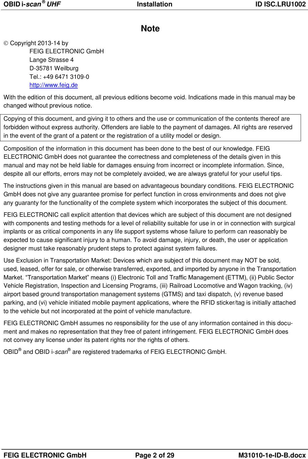
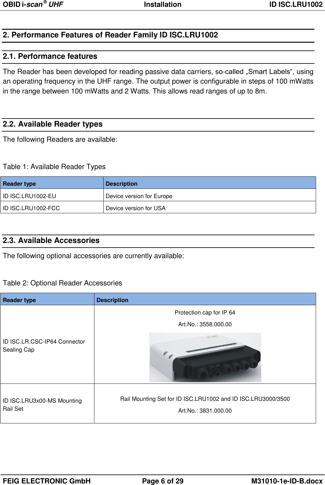
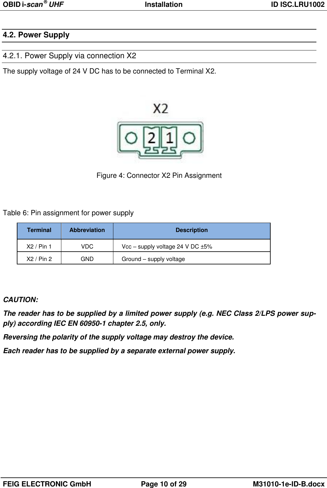

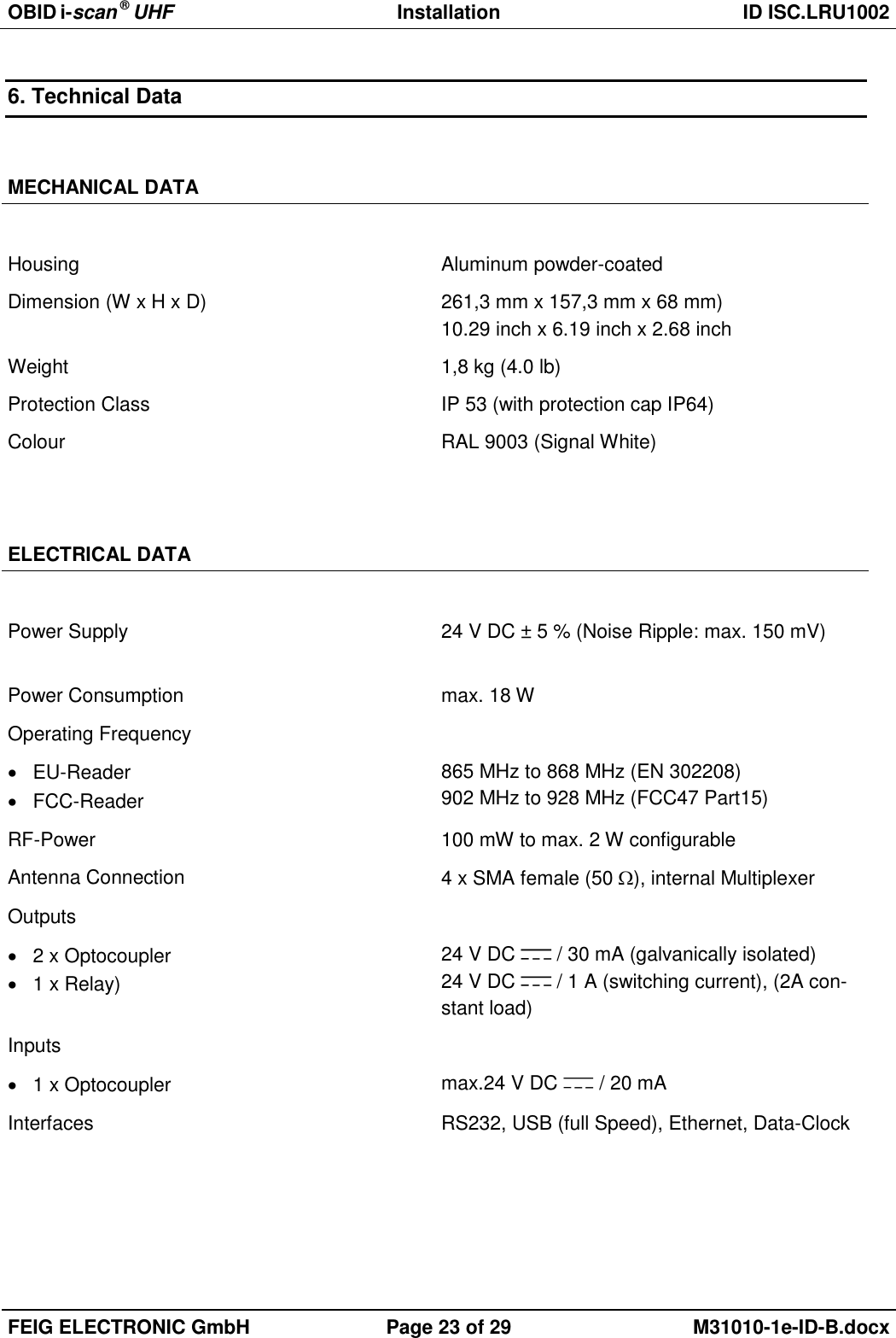
![OBID i-scan ® UHF Installation ID ISC.LRU1002 FEIG ELECTRONIC GmbH Page 19 of 29 M31010-1e-ID-B.docx 5. Operating and Display Elements 5.1. Status LEDs Table 13: Configuration of the LEDs Green Yellow Red Description ON OFF ON Boot sequence (ca.10s) after power on FLASH OFF OFF Normal Reader operation (without Host communication) FLASH FLASH OFF Reader receives a valid protocol from host FLASH OFF ON RF Warning [0x84] (without host communication) FLASH (alternat-ing) OFF FLASH (alternat-ing) Firmware Activation necessary [0x17] / Wrong Firmware [0x18] FLASH (synchro-nous) OFF FLASH (synchro-nous) RFC Hardware Error [0xF1] OFF FLASH (synchro-nous) FLASH (synchro-nous) Hardware Warning (EEPROM Error / RFC not detected) Firmware Update: FLASH FLASH FLASH Firmware transfer from host to reader (Please do not switch off the reader or disconnect the interface cable) (light in sequence) Configurations-Reset: FLASH FLASH FLASH While T1 is pushed and hold for maximal 5s (light in sequence) ON ON ON After T1 has been pushed and hold for 5s. Configuration Reset has been finished. ANT 1- 4 RUN Host Communication Warning RFU](https://usermanual.wiki/Feig-Electronic/LRU1002/User-Guide-2220584-Page-19.png)
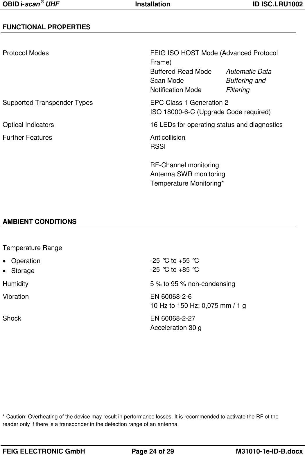
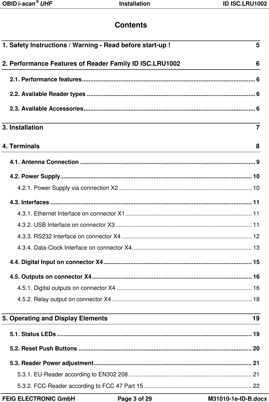
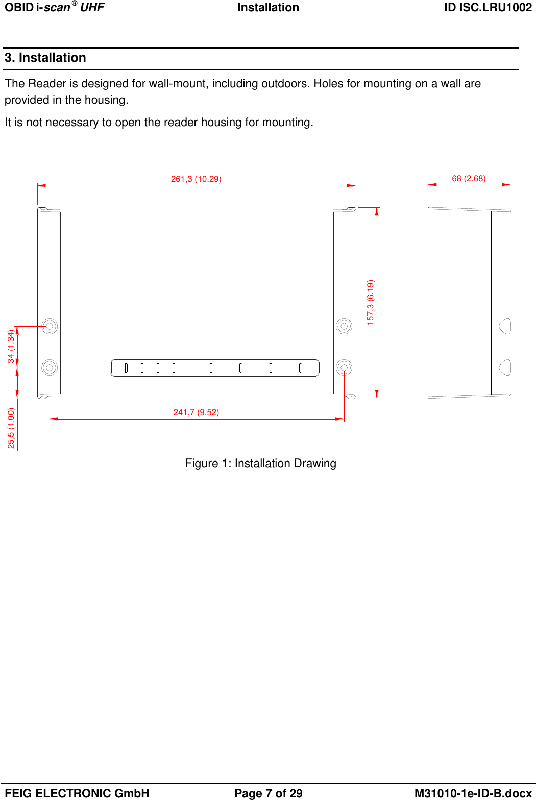
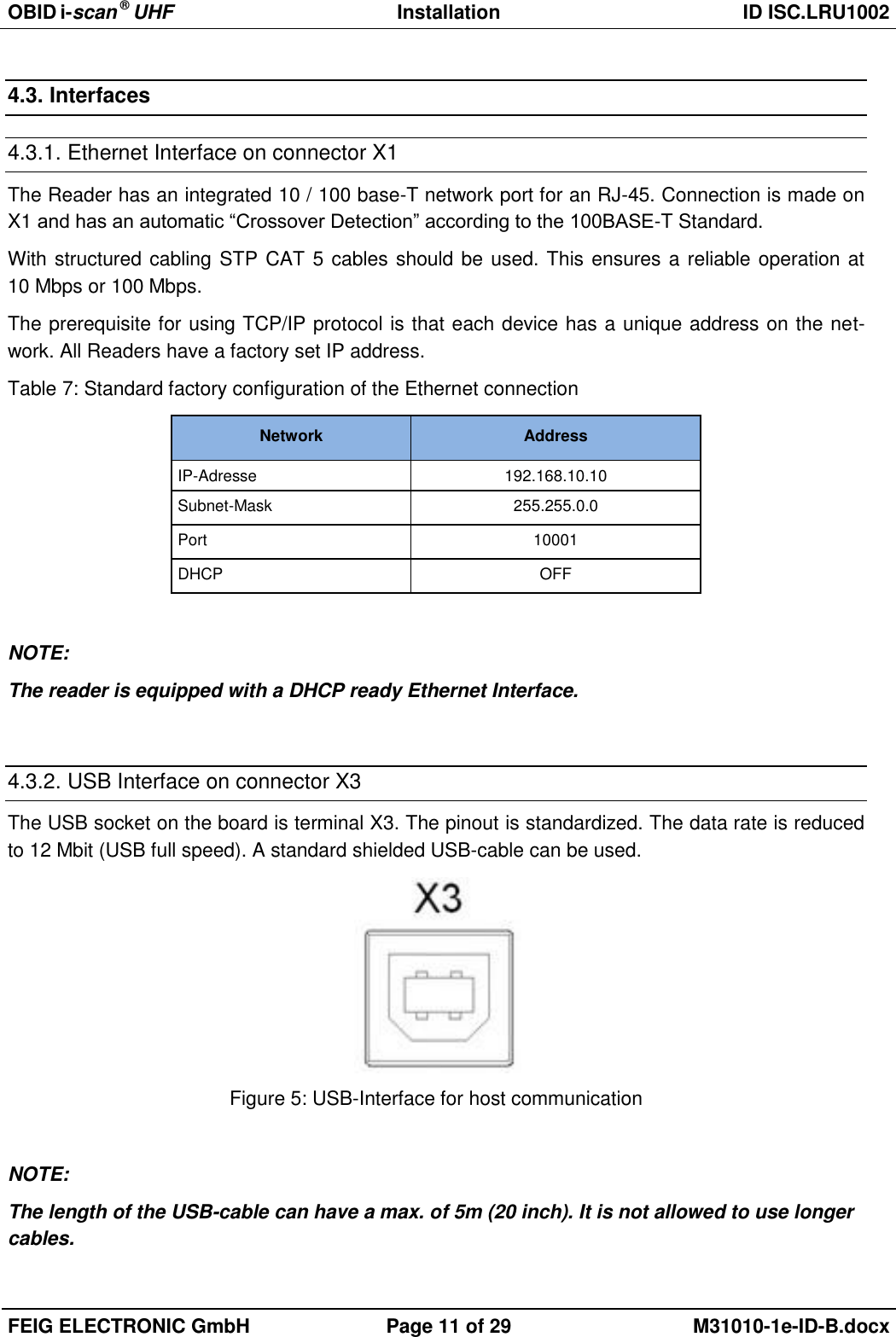
![OBID i-scan ® UHF Installation ID ISC.LRU1002 FEIG ELECTRONIC GmbH Page 20 of 29 M31010-1e-ID-B.docx ANT 1 – 4: Green HF Power switched on Blue Tag-Detect Red Antenna impedance error (> 50Ohm or <50Ohm) 5.2. Reset Push Buttons Figure 15 shows the position of the reset push button T1. At the right side of the connector X4 the push button T1 is positioned. It is located housing. With the push button T1 a complete configuration reset can be a reset you should use a paper clip and push the button T1 for at least 5 s until (left side) are switched on continuously, see 5.1. Status LEDs Table 13: Configuration of the LEDs Afterwards the green LED and the red LED are flashing alternating. Figure 15: Position of the reset-switch T1 To finish the hardware configuration reset a reboot of the reader is mandatory. This can either be performed by plugging off the power supply or by sending the command System Reset [0x64] in Mode [0x00] RF-Controller to the reader. Figure 16: System Reset [0x64]](https://usermanual.wiki/Feig-Electronic/LRU1002/User-Guide-2220584-Page-20.png)
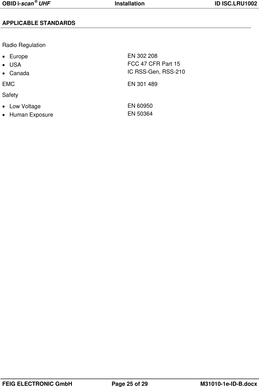
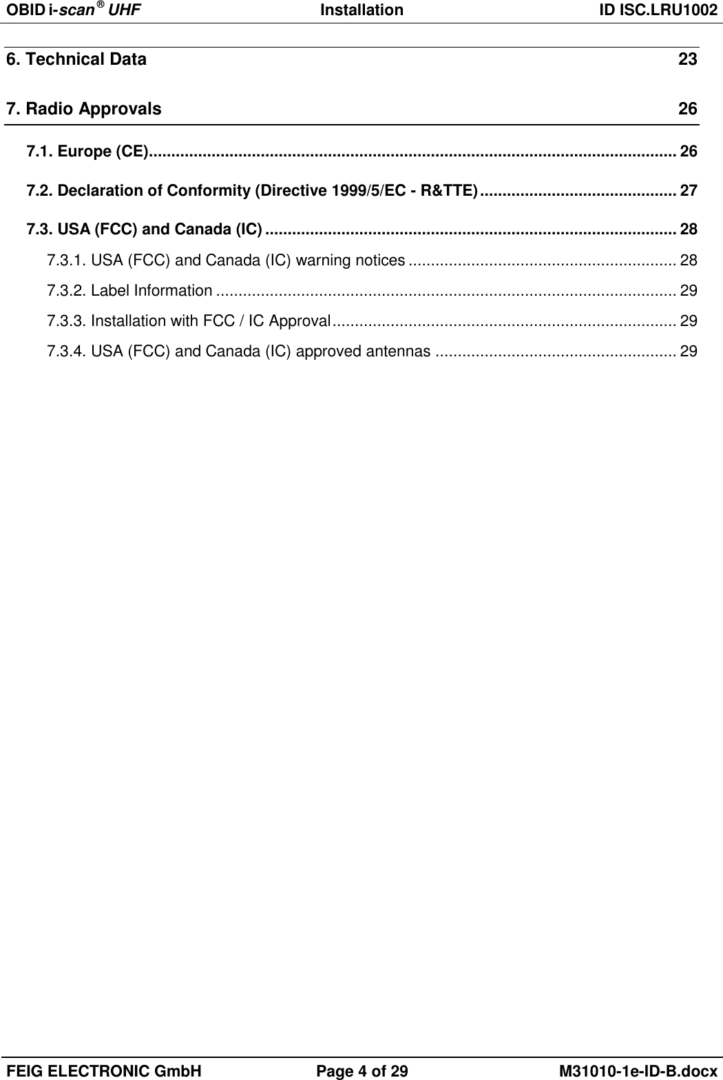
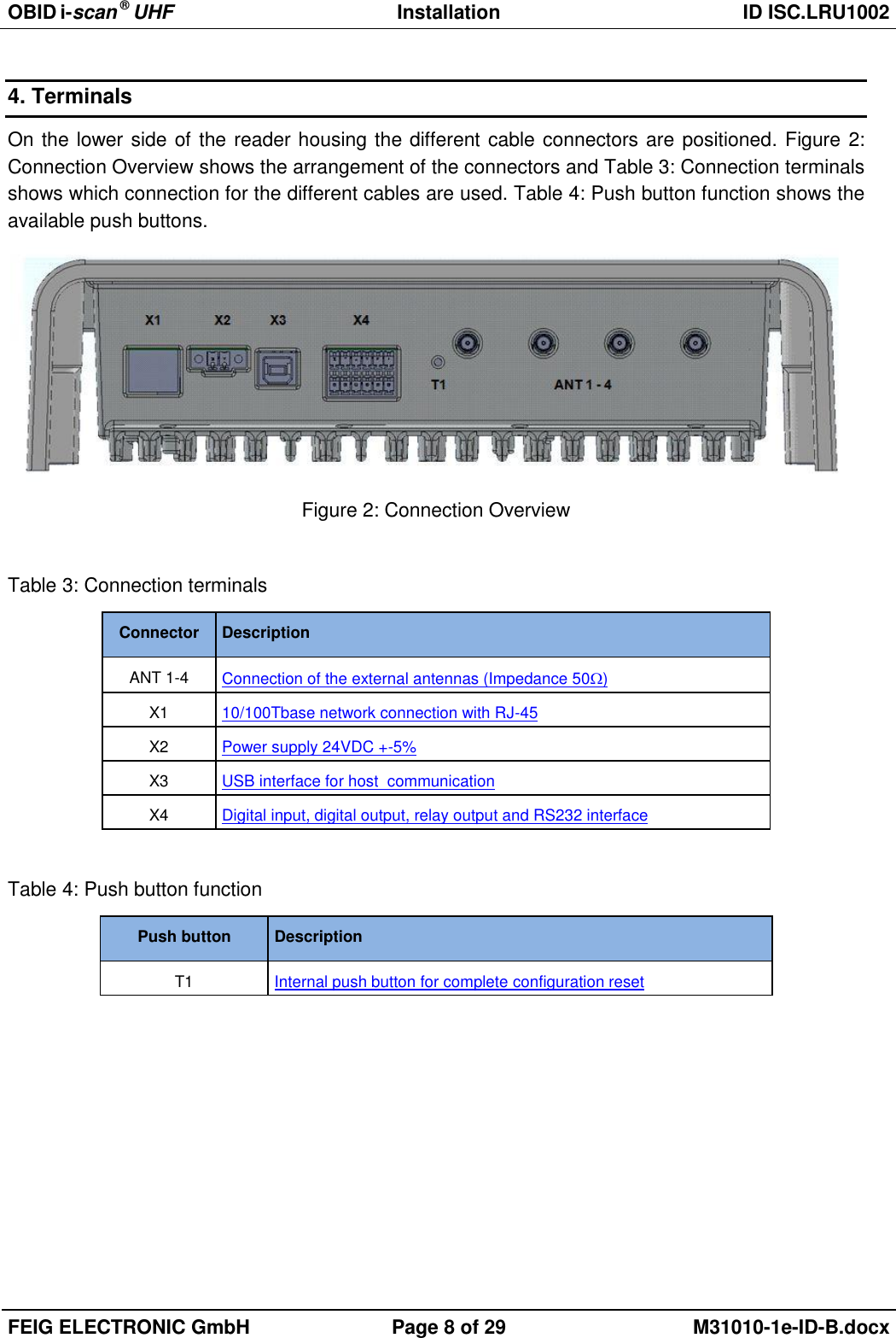
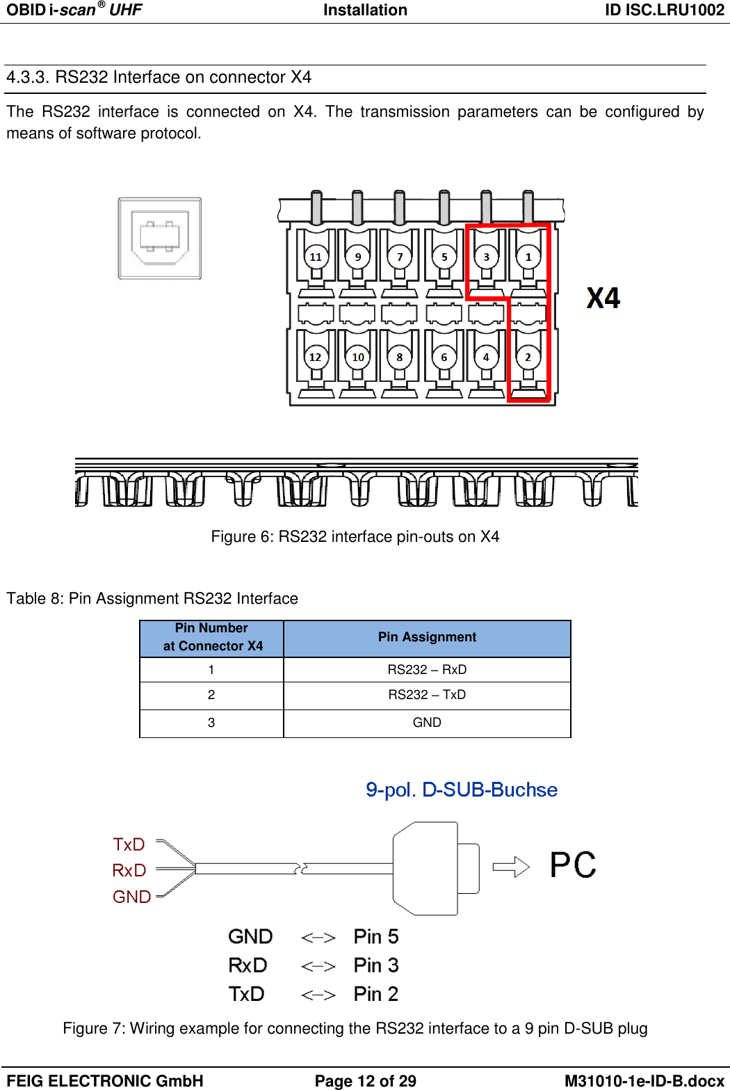
![OBID i-scan ® UHF Installation ID ISC.LRU1002 FEIG ELECTRONIC GmbH Page 21 of 29 M31010-1e-ID-B.docx 5.3. Reader Power adjustment To achieve the optimum reading performance it is necessary to set the reader output power to the highest allowed value. This depends on the used reader type (EU / FCC) and the regulation in the country were the reader is used. 5.3.1. EU-Reader according to EN302 208 According to the standard EN302 208 the maximum radiated power is 2 W e.r.p. (Effective Radiat-ed Power) in countries of the European Union. The in the reader configured output power Pout de-pends on the antenna gain in dBi and the attenuation of the antenna cable. If a circular polarized antenna is used the antenna gain [dBic] can be reduced by 3dB. At a linear polarized antenna the maximum linear antenna gain [dBi] must be used. POut = Perp - Antenna Gain + Cable loss + 2,1dB** ** Correction Factor to convert the radiated power from e.r.p to e.i.r.p. For the calculation of the reader output power POut an Excel file „Calc-RF-Power.xls“ can be used. Available from Feig Electronic GmbH. Example: ** linear antenna = „0“, circular antenna = „1“ Figure 17: Calculation of the output power In Figure 17 the allowed antenna power is shown for the use of the FEIG standard antenna ANT.U600/270 –EU and a 6m long Belden H155 coaxial cable.](https://usermanual.wiki/Feig-Electronic/LRU1002/User-Guide-2220584-Page-21.png)
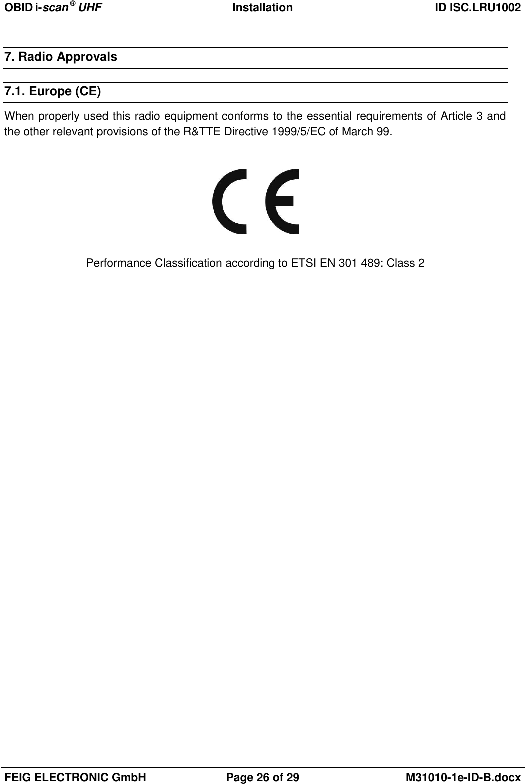
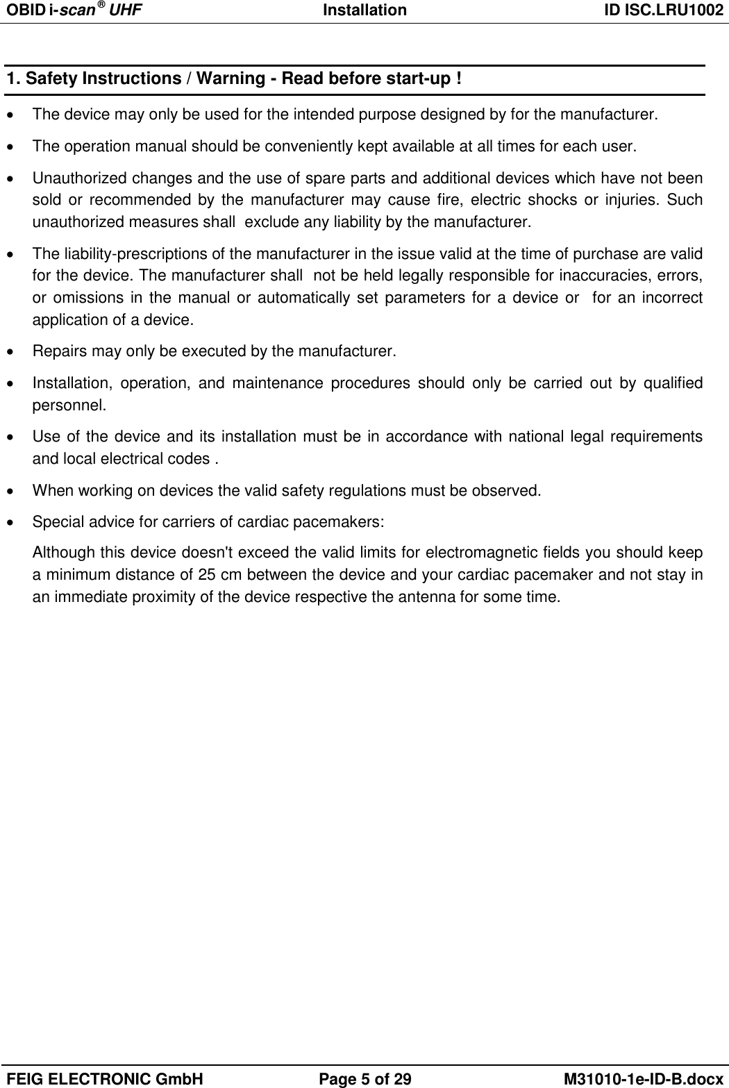
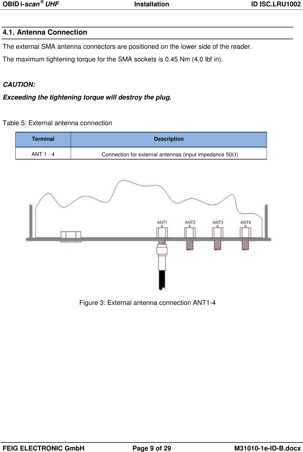
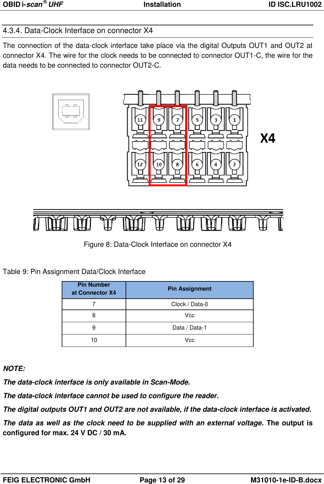
![OBID i-scan ® UHF Installation ID ISC.LRU1002 FEIG ELECTRONIC GmbH Page 22 of 29 M31010-1e-ID-B.docx 5.3.2. FCC-Reader according to FCC 47 Part 15 According to the FCC approval, Title 47, Part15 the maximum output power of the reader is limited to 1 W (30dBm). The maximum radiated power of the antenna should not increase more then 4 W e.i.r.p. Due to these facts two different cases have to be considered: If a linear polarized antenna is used which gain is less then 6 dBi (factor 4), or if a circular polarized antenna is used which gain is less then 9dBic the reader can always be configured to an output power of 1W. Antenna Gain < 6dBi → Pout = 1 W This would be the case if the FEIG standard antennas ANT.U170/170 -FCC (4dBic) or ANT.U270/270 -FCC (8,7dBic) are used. If an antenna is used which gain is more then 6dBi (9dBic) it is necessary to consider the antenna gain and the attenuation of the antenna cable to calculate the right output power. If a circular polar-ized antenna is used the antenna gain [G]=dBic can be reduced by 3dB. This is the case if the FEIG standard antenna ANT.U600/270 -FCC is used. In this configuration the maximum output power of the reader can be calculated in the following way. POut = 36 dBm (4 W e.i.r.p) – Antenna Gain (in dBi) + Cable Loss (in dB) POut = 36 dBm (4 W e.i.r.p) – Antenna Gain (in dBic) – 3 dB + Cable Loss (in dB) The antenna gain of the circular polarized standard antenna ANT.U600/270 is 10,5 dBic. This could be compared with a gain of 7,5 dBi of a linear polarized antenna (10,5 dBic – 3 dB). Example 1: Antenna ANT.U600/270 and 2 m Belden H155 Coaxial Cable: Pout= 36 dBm – 10,5 dBic + 3 dB + 0,6 dB Pout= 36 dBm – 7,5 dBi + 0,6 dB Pout= 29,1 dBm Reader Configuration = 0,8 Watt Example 2: Antenna ANT.U600/270 and 6m Belden H155 Coaxial Cable: Pout= 36 dBm – 10,5 dBic + 3 dB + 1,8 dB Pout= 36 dBm – 7,5 dBi + 1,8 dB Pout= 30,3 dBm Reader Configuration = 1,0 Watt According to Example 2 it will only be necessary to adapt the output power of the reader when the antenna ANT.U600/270 is used if the length of the antenna cable is less then 6m.](https://usermanual.wiki/Feig-Electronic/LRU1002/User-Guide-2220584-Page-22.png)