Feig Electronic LRU1002A RFID UHF Reader User Manual manual
Feig Electronic GmbH RFID UHF Reader manual
Contents
manual
INSTALLATION
final – public (B)
2017-05-16 – M61110-2e-ID-B.docx
ID ISC.LRU1002 (EU: 4127.001.00; FCC: 4128.001.00)
UHF Long Range Reader

IDENTIFICATION
Installation
ID ISC.LRU1002
FEIG ELECTRONIC GmbH
Page 2 of 32
M61110-2e-ID-B.docx
Note
Copyright 2017 by
FEIG ELECTRONIC GmbH
Lange Strasse 4
D-35781 Weilburg
Tel.: +49 6471 3109-0
http://www.feig.de
With the edition of this document, all previous editions become void. Indications made in this manual may be
changed without previous notice.
Copying of this document, and giving it to others and the use or communication of the contents thereof are
forbidden without express authority. Offenders are liable to the payment of damages. All rights are reserved
in the event of the grant of a patent or the registration of a utility model or design.
Composition of the information in this document has been done to the best of our knowledge. FEIG
ELECTRONIC GmbH does not guarantee the correctness and completeness of the details given in this
manual and may not be held liable for damages ensuing from incorrect or incomplete information. Since,
despite all our efforts, errors may not be completely avoided, we are always grateful for your useful tips.
The instructions given in this manual are based on advantageous boundary conditions. FEIG ELECTRONIC
GmbH does not give any guarantee promise for perfect function in cross environments and does not give
any guaranty for the functionality of the complete system which incorporates the subject of this document.
FEIG ELECTRONIC call explicit attention that devices which are subject of this document are not designed
with components and testing methods for a level of reliability suitable for use in or in connection with surgical
implants or as critical components in any life support systems whose failure to perform can reasonably be
expected to cause significant injury to a human. To avoid damage, injury, or death, the user or application
designer must take reasonably prudent steps to protect against system failures.
FEIG ELECTRONIC GmbH assumes no responsibility for the use of any information contained in this docu-
ment and makes no representation that they free of patent infringement. FEIG ELECTRONIC GmbH does
not convey any license under its patent rights nor the rights of others.

IDENTIFICATION
Installation
ID ISC.LRU1002
FEIG ELECTRONIC GmbH
Page 3 of 32
M61110-2e-ID-B.docx
Contents
1. Safety Instructions / Warning - Read before start-up ! 5
2. Performance Features of Reader Family ID ISC.LRU1002 6
2.1. Performance features .......................................................................................................... 6
2.2. Available reader types ......................................................................................................... 6
3. Installation 7
4. Terminals 8
4.1. Antenna Connection ............................................................................................................ 9
4.2. Power Supply ...................................................................................................................... 10
4.2.1. Power Supply via connection X2 .................................................................................. 10
4.3. Interfaces ............................................................................................................................ 11
4.3.1. Ethernet Interface on connector X1 .............................................................................. 11
4.3.2. USB Mini Interface on connector X3 ............................................................................. 11
4.3.2.1. USB-Stick Service-Functions ........................................................................... 12
4.3.2.2. Reading of Log and Service Data..................................................................... 12
4.3.2.3. Storing the reader configuration on a USB flash drive ..................................... 13
4.3.2.4. Copy the configuration onto the reader (Config-Cloning) ................................. 13
4.3.3. RS232 Interface on connector X4 ................................................................................. 15
4.3.4. Data-Clock Interface on connector X4 .......................................................................... 16
4.4. Inputs and Outputs on connector X4 ............................................................................... 18
4.4.1. 24 V DC voltage on connector X4 ................................................................................ 18
4.4.2. Digital Inputs on connector X4 ...................................................................................... 19
4.4.3. Digital outputs on connector X4 .................................................................................... 20
4.4.4. Relay output on connector X4 ...................................................................................... 21
5. Operating and Display Elements 22
5.1. Status LED .......................................................................................................................... 22
5.2. Reset Push Button T1 ........................................................................................................ 23
5.3. Reader Power Adjustment ................................................................................................. 24

IDENTIFICATION
Installation
ID ISC.LRU1002
FEIG ELECTRONIC GmbH
Page 4 of 32
M61110-2e-ID-B.docx
5.3.1. EU reader according to EN302 208 .............................................................................. 24
5.3.2. FCC-Reader according to FCC 47 Part 15 ................................................................... 25
6. Technical Data 26
7. Radio Approvals 29
7.1. Europe (CE) ......................................................................................................................... 29
7.2. USA (FCC) and Canada (IC) ............................................................................................... 30
7.2.1. USA (FCC) and Canada (IC) warning notices .............................................................. 30
7.2.2. Label Information .......................................................................................................... 31
7.2.3. Installation with FCC / IC Approval ............................................................................... 31
7.2.4. USA (FCC) and Canada (IC) approved antennas ........................................................ 31
ANNEX A - Accessories 32

IDENTIFICATION
Installation
ID ISC.LRU1002
FEIG ELECTRONIC GmbH
Page 5 of 32
M61110-2e-ID-B.docx
1. Safety Instructions / Warning - Read before start-up !
The device may only be used for the intended purpose designed by for the manufacturer.
The operation manual should be conveniently kept available at all times for each user.
Unauthorized changes and the use of spare parts and additional devices which have not been
sold or recommended by the manufacturer may cause fire, electric shocks or injuries. Such
unauthorized measures shall exclude any liability by the manufacturer.
The liability-prescriptions of the manufacturer in the issue valid at the time of purchase are valid
for the device. The manufacturer shall not be held legally responsible for inaccuracies, errors,
or omissions in the manual or automatically set parameters for a device or for an incorrect
application of a device.
Repairs may only be executed by the manufacturer.
Installation, operation, and maintenance procedures should only be carried out by qualified
personnel.
Use of the device and its installation must be in accordance with national legal requirements
and local electrical codes .
When working on devices the valid safety regulations must be observed.
This device is not suitable to be used in places where children are present. Prevent children
access to the device.
Equipment is intended for use only in restricted access area.
Special advice for carriers of cardiac pacemakers:
Although this device doesn't exceed the valid limits for electromagnetic fields you should keep
a minimum distance of 25 cm between the device and your cardiac pacemaker and not stay in
an immediate proximity of the device respective the antenna for some time.
IDENTIFICATION
Installation
ID ISC.LRU1002
FEIG ELECTRONIC GmbH
Page 6 of 32
M61110-2e-ID-B.docx
2. Performance Features of Reader Family ID ISC.LRU1002
2.1. Performance features
The reader has been developed for reading passive data carriers, so-called „Smart Labels“, using
an operating frequency in the UHF range. The output power is configurable in the range between
100 mW and 2 W. This allows read ranges of up to 12 m.
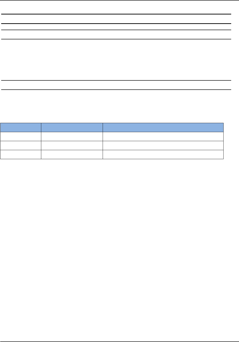
2.2. Available reader types
The following readers are available:
Table 1: Available Reader Types
Order Number
Reader type
Description
4127.001.00
ID ISC.LRU1002-EU
Device version for Europe
4128.001.00
ID ISC.LRU1002-FCC
Device version for North America
4861.000.00
ID ISC.LRU1002-MA
Device version for Morocco
IDENTIFICATION
Installation
ID ISC.LRU1002
FEIG ELECTRONIC GmbH
Page 7 of 32
M61110-2e-ID-B.docx
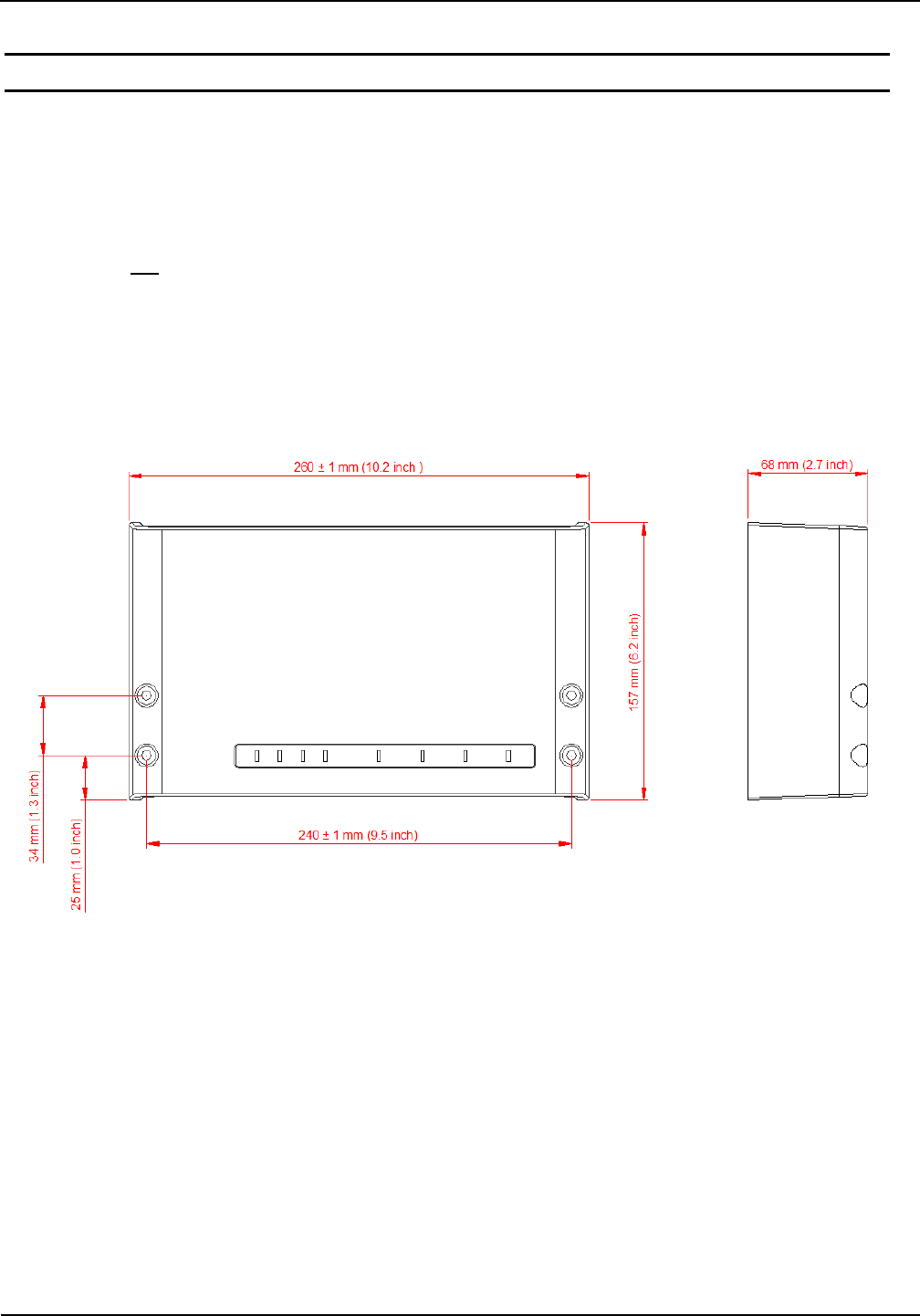
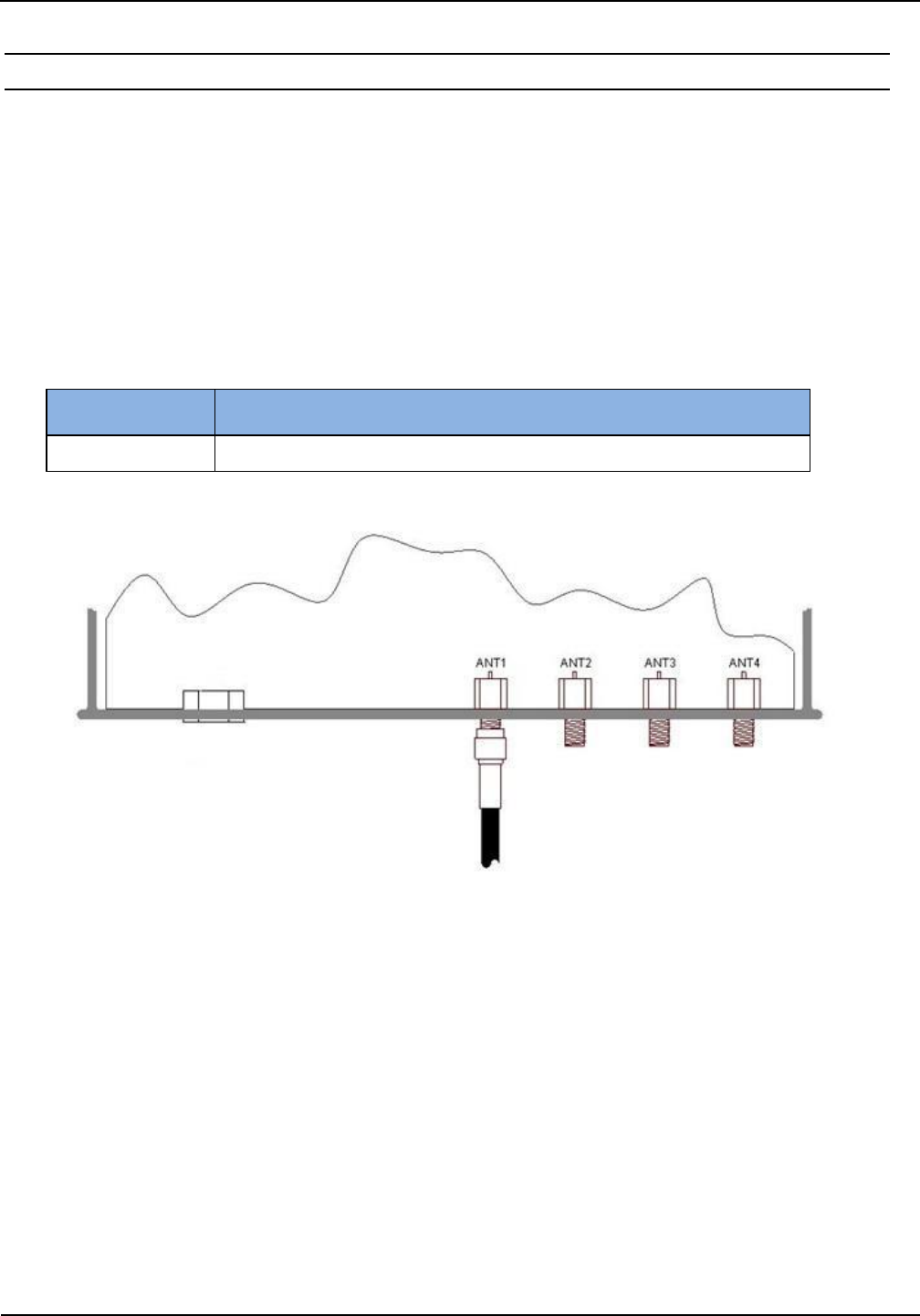
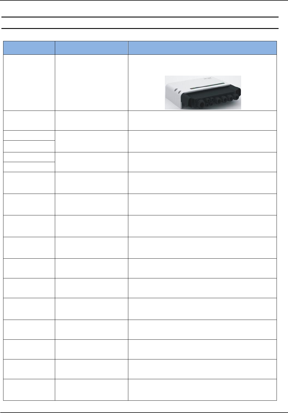
3. Installation
The Reader is designed for wall-mount, including outdoors. Outdoors the reader should be
mounted like shown in the picture below to ensure the watertightness of the device.
Holes for mounting on a wall with countersunk head screws are provided in the housing. The
maximum head screw diameter should not exceed 8,0 mm. The thread diameter is 5,3 mm (M5
screws). The screws must have a minimum length of 45 mm depending on the installation
situation. It is not necessary to open the reader housing for installation.
Figure 1: Installation Drawing
IDENTIFICATION
Installation
ID ISC.LRU1002
FEIG ELECTRONIC GmbH
Page 8 of 32
M61110-2e-ID-B.docx
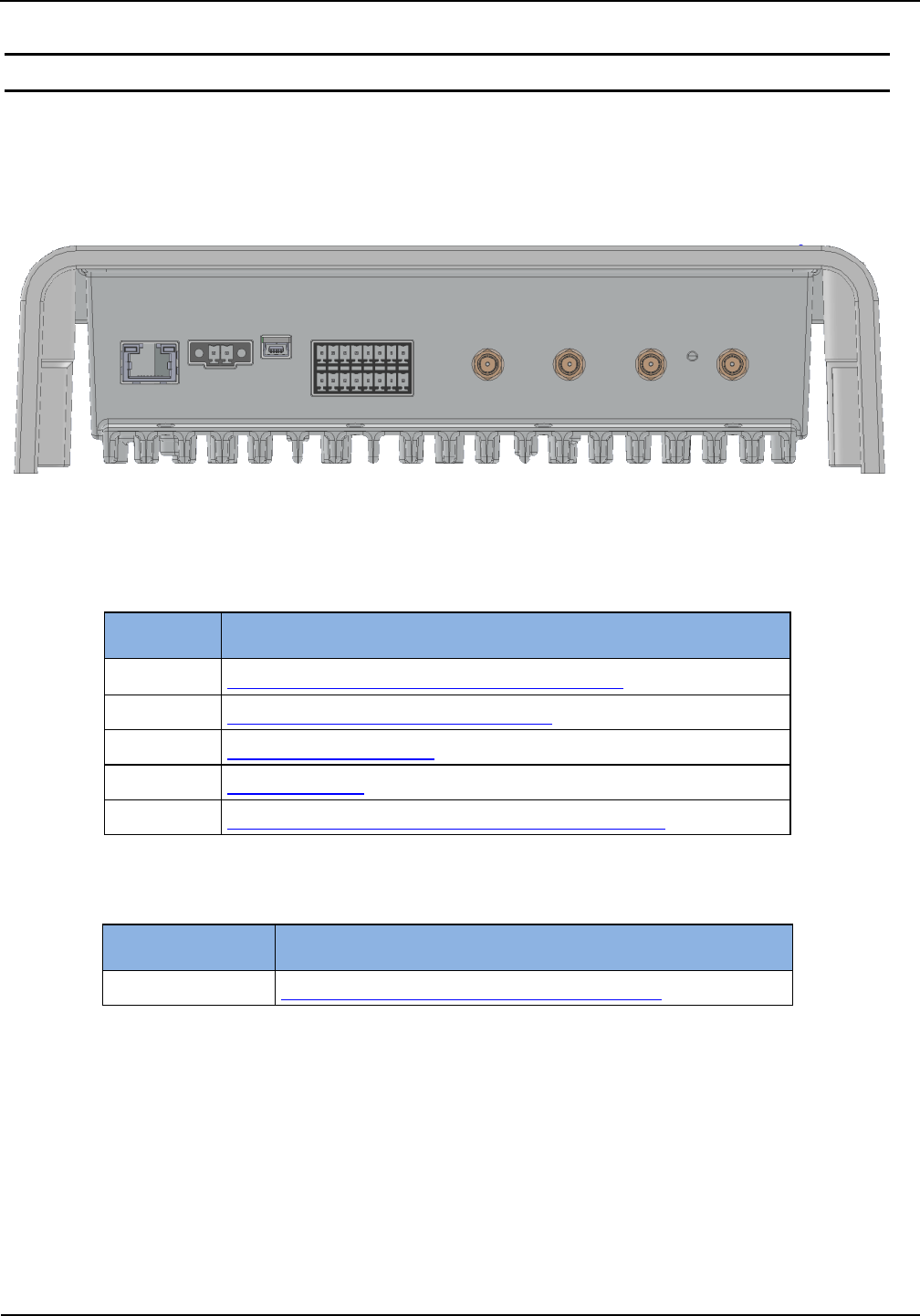
4. Terminals
On the lower side of the reader housing different connectors are positioned. Figure 2 shows the
arrangement of the connectors and Table 2: Connection terminals gives an overview on the avail-
able interfaces and signals. Table 3: Push button function shows the available push buttons.
Figure 2: Connection Overview
Table 2: Connection terminals
Connector
Description
ANT 1-4
Connection of the external antennas (Impedance 50)
X1
10/100Tbase network connection with RJ-45
X2
Power supply 24VDC ± 20%
X3
USB Mini Interface
X4
Digital input, digital output, relay output and RS232 interface
Table 3: Push button function
Push button
Description
T1
Internal push button for complete configuration reset
ANT 1 - 4
X2
X3
X1
X4
T1
IDENTIFICATION
Installation
ID ISC.LRU1002
FEIG ELECTRONIC GmbH
Page 9 of 32
M61110-2e-ID-B.docx
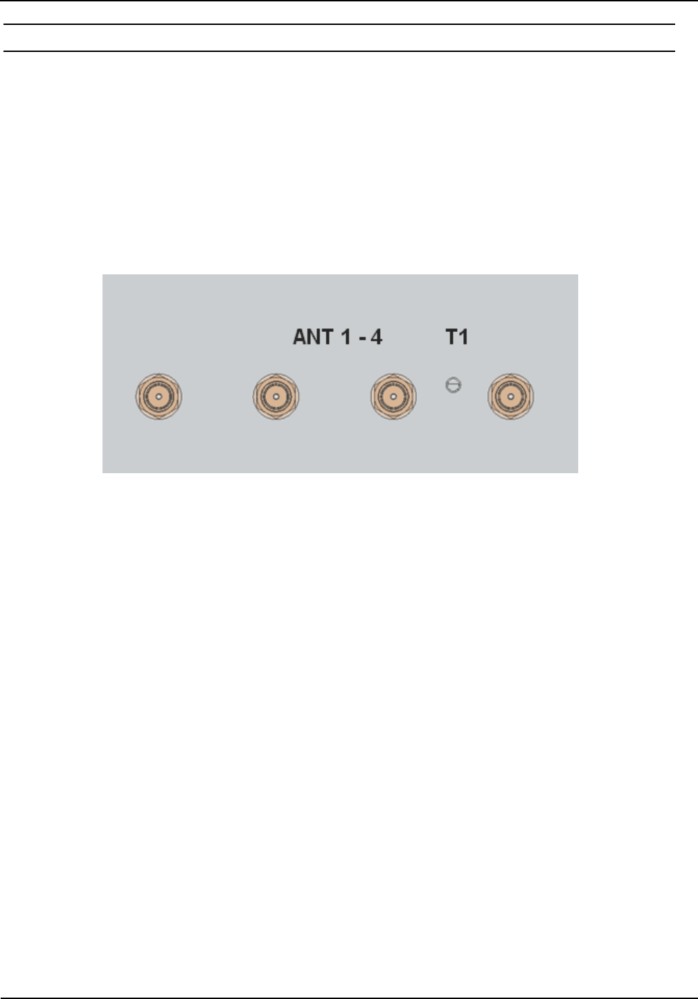
4.1. Antenna Connection
The external SMA antenna connectors are positioned on the lower side of the reader.
The maximum tightening torque for the SMA sockets is 0.45 Nm (4.0 lbf in).
For supplying a DC voltage to external components e.g. the UHF antenna multiplexer ID
ISC.ANT.UMUX, it is possible to enable a supply voltage (24 V DC / max. 500mA) on the antenna
cable. This need to be configured in the reader.
Table 4: External antenna connection
Terminal
Description
ANT 1 - 4
Connection for external antennas (input impedance 50)
Figure 3: External antenna connection ANT1-4
CAUTION:
Exceeding the tightening torque will destroy the plug.
The activation of the DC voltage on the antenna cable can damage the antennas from other
manufacturers. It is recommend to use high resistance UHF antennas. For any further ques-
tions please contact the technical support.
IDENTIFICATION
Installation
ID ISC.LRU1002
FEIG ELECTRONIC GmbH
Page 10 of 32
M61110-2e-ID-B.docx
4.2. Power Supply
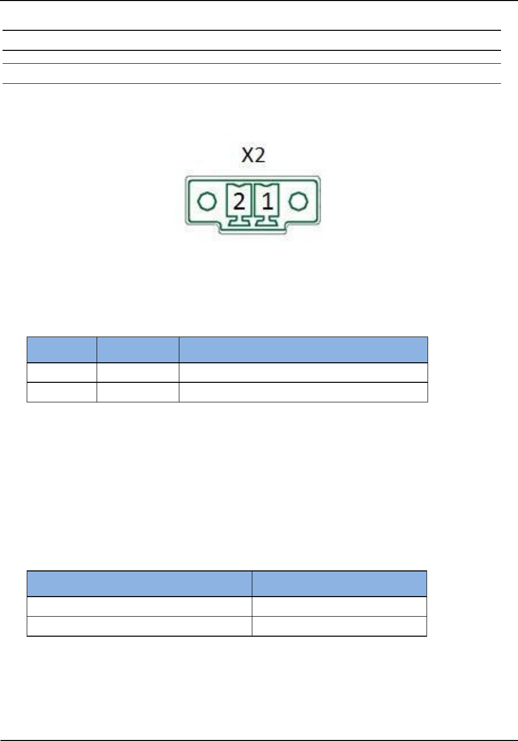
4.2.1. Power Supply via connection X2
The supply voltage of 24 V DC has to be connected to Terminal X2.
Figure 4: Connector X2 Pin assignment for power supply
Table 5: Pin assignment for power supply
Terminal
Abbreviation
Description
X2 / Pin 1
VDC
Supply voltage 24 V DC ±20 %
X2 / Pin 2
GND
Ground – supply voltage
CAUTION:
The reader has to be supplied by a limited power supply according EN 62368-1 Chapter Q.1,
or with a NEC Class 2/LPS certified power supply.
Each reader has to be supplied by a separate external power supply.
Reversing the polarity of the supply voltage on X2 may destroy the device.
External wiring for the power supply must fulfil the following norms/validation procedure:
Conductor Cross-section
Validation procedure
from 0,5 mm2 or bigger
IEC 60332-1-2 and IEC 60332-1-3
smaller than 0,5 mm2
IEC 60332-2-1 and IEC 60332-2-2
IDENTIFICATION
Installation
ID ISC.LRU1002
FEIG ELECTRONIC GmbH
Page 11 of 32
M61110-2e-ID-B.docx
4.3. Interfaces
4.3.1. Ethernet Interface on connector X1
The Reader has an integrated 10 / 100 base-T network port for an RJ-45. Connection is made on
X1 and has an automatic “Crossover Detection” according to the 100BASE-T Standard.
With structured cabling STP CAT 5 cables should be used. This ensures a reliable operation at
10 Mbps or 100 Mbps.
The prerequisite for using TCP/IP protocol is that each device has a unique IP address on the net-
work. All Readers have a factory set IP address.
Table 6: Standard factory configuration of the Ethernet connection
Network
Address
IP-Adresse
192.168.10.10
Subnet-Mask
255.255.0.0
Port
10001
DHCP
OFF
NOTE:
The reader is equipped with a DHCP ready Ethernet Interface.
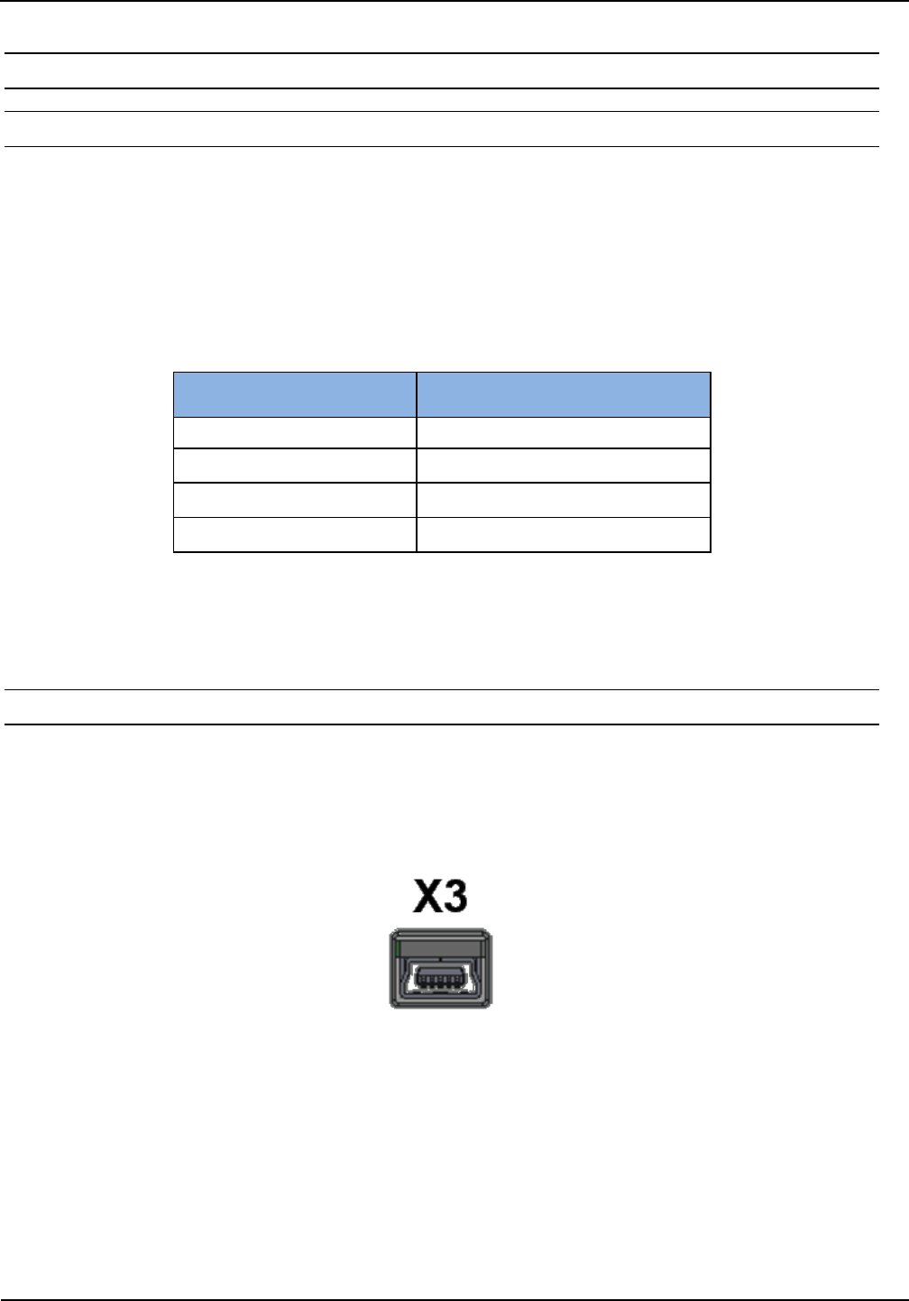
4.3.2. USB Mini Interface on connector X3
The reader is equipped with a USB on-the-go interface. This can either be used to connect the
reader to a host system or by means of a special on-the-go adaptor for connection of a USB mem-
ory stick to the reader. In both cases the connection is carried out via terminal X3. The pinout is
standardized.
Figure 5: USB-Interface for host communication
A standard shielded USB-cable can be used for connection of the reader to a host system. The
data rate is reduced to 12 Mbit (USB full speed).
NOTE:
The length of the USB-cable can have a max. of 5m (20 inch). It is not allowed to use longer
cables.
IDENTIFICATION
Installation
ID ISC.LRU1002
FEIG ELECTRONIC GmbH
Page 12 of 32
M61110-2e-ID-B.docx
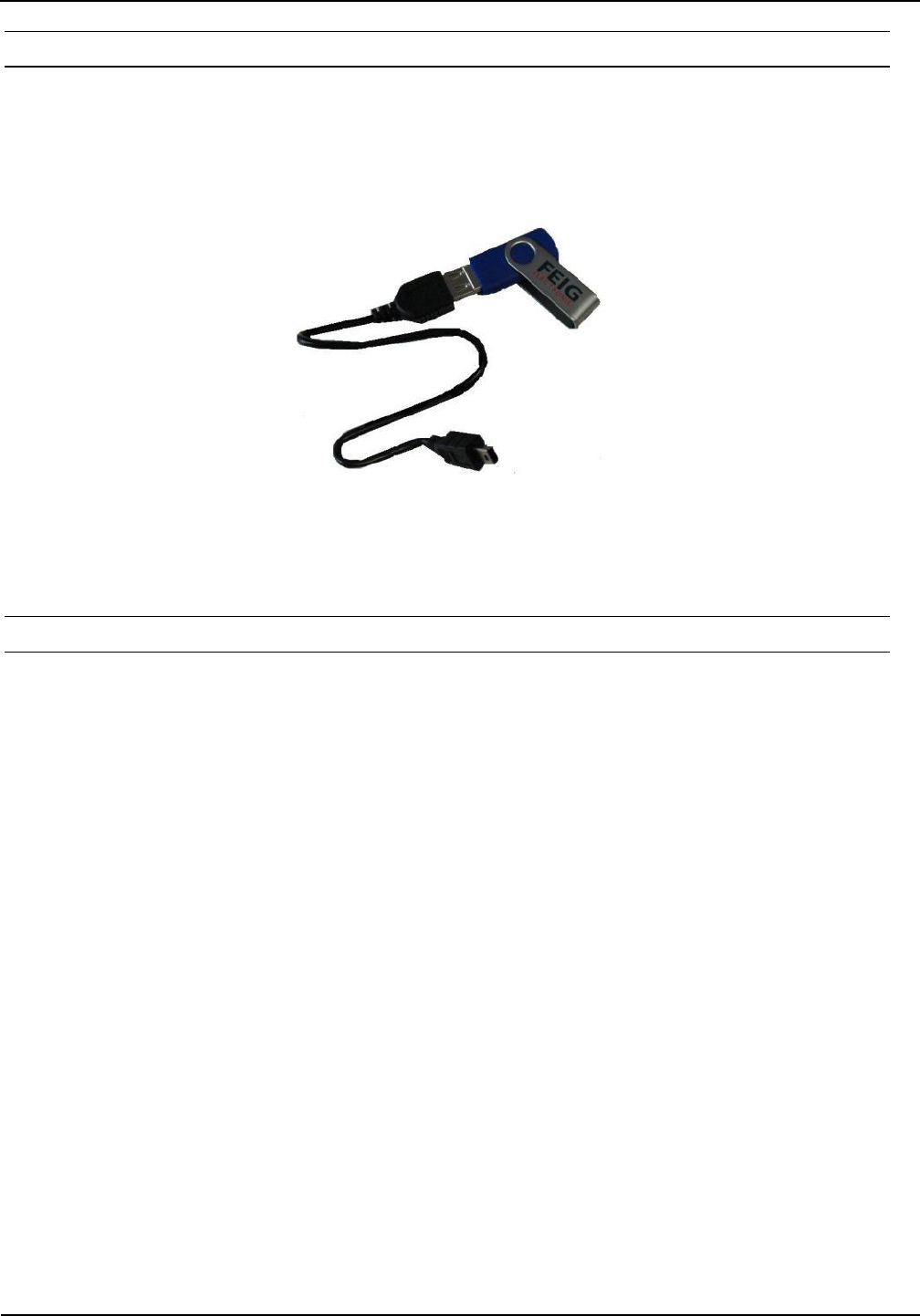
4.3.2.1. USB-Stick Service-Functions
Via an optionally available USB On-The-Go adapter cable, the interface can be converted to a
USB host interface. The adapter cable allows the connection of a USB memory stick to the reader.
By means of the USB stick various service functions can be carried out e.g. the read-out of log and
service files and uploading of a configuration file.
Figure 6: USB On-The-Go adapter cable
4.3.2.2. Reading of Log and Service Data
After plug-in of the USB flash drive on the running ID ISC.LRU1002 the reader will generate a sub-
directory on the root directory of the USB flash drive. The name of the subdirectory is equal to the
Device-ID of the connected reader (see type plate of the reader). Within this subdirectory the
reader stores device information like firmware version and IP-address in the file INFO.LOG. If there
exist already such a file for the same reader the file will be updated with the information and the
current date and time.
Additionally the files ACTION.LOG and SERVICE.LOG will be generated and stored for service
purposes on the USB flash drive. The meaning of the CONFIG.INI will be described in the next
chapter.
After plug-in of the USB flash drive the green and red status LED of the ID ISC.LRU1002 are per-
manently lit as long as the USB flash drive is actively used by the reader. When the USB actions
are completed successfully, the red LED is switched off and the green LED starts flashing. The
USB flash drive can be removed after the red LED is switched off. If the USB actions failed the red
status LED starts flashing until the USB flash drive is removed.
NOTE:
After plug-in of the USB flash drive the status LEDs of the reader shall be monitored.
The USB flash drive shall only be removed from the reader if the USB actions have been
completed and the flash drive is not in use anymore.

IDENTIFICATION
Installation
ID ISC.LRU1002
FEIG ELECTRONIC GmbH
Page 13 of 32
M61110-2e-ID-B.docx
4.3.2.3. Storing the reader configuration on a USB flash drive
While connecting the USB flash drive on a running reader, the reader will store the configuration as
a editable and readable CSV-file (CONFIG.INI) on the USB flash drive. This file will be stored in
the main directory for easy coping of the configuration (4.3.2.4. Copy the configuration onto the
reader (Config-Cloning)). Additionally the same file will be stored in the subdirectory named after
the according Device-ID (see type plate of the reader). Thereby it is possible to store several con-
figuration files on the same USB flash drive.
All not locked configuration pages (CFG pages) including the interface parameter will be copied
from the reader onto the USB flash drive. Password protected configuration pages will not be cop-
ied.
After plug-in of the USB flash drive the green and red status LED are permanently lit as long as the
USB flash drive is actively used by the reader. When the USB actions are completed successfully,
the red LED is switched off and the green LED starts flashing. The USB flash drive can be re-
moved after the red LED is switched off. If the USB actions failed the red status LED starts flashing
until the USB flash drive is removed.
Note:
If there exists already a configuration file CONFIG.INI on the main directory of the USB flash
drive, the old file will be overwritten by the new configuration file.
Configuration pages which are protected by a password (see CFG0) will be not stored on
the USB flash drive. No error message will appear.
After connecting the USB flash drive on the reader USB port, the reader LEDs should be
observed.
The USB flash drive shall only be removed from the reader if the USB actions have been
completed and the flash drive is not in use anymore.
4.3.2.4. Copy the configuration onto the reader (Config-Cloning)
In order to connecting the USB flash drive on the reader USB port and copy the configuration from
the USB flash drive onto the reader, it is necessary to switch off the reader before plug-in the USB
flash drive. After switching on the reader the boot process will look for a connected USB flash drive
and will copy the existing configuration file onto the reader.
It must be ensured that no configuration page (CFG page) is locked inside the reader. If configura-
tion pages are locked the configuration file will not be copied onto the reader. If single configuration
parameters in the configuration file were out of range and invalid the configuration file will not be
copied onto the reader as well.
After the copy process has been finished the green LED will start flashing and the red LED goes
off. After the red LED goes off the USB flash drive can be disconnected. If the USB actions failed
the red status LED starts flashing until the USB flash drive is removed.

IDENTIFICATION
Installation
ID ISC.LRU1002
FEIG ELECTRONIC GmbH
Page 14 of 32
M61110-2e-ID-B.docx
Note:
Connecting an USB flash drive on a running reader will always overwrite an existing con-
figuration file in the main directory on the USB flash drive (see 4.3.2.3. Storing the reader
configuration on a USB flash drive).
IDENTIFICATION
Installation
ID ISC.LRU1002
FEIG ELECTRONIC GmbH
Page 15 of 32
M61110-2e-ID-B.docx
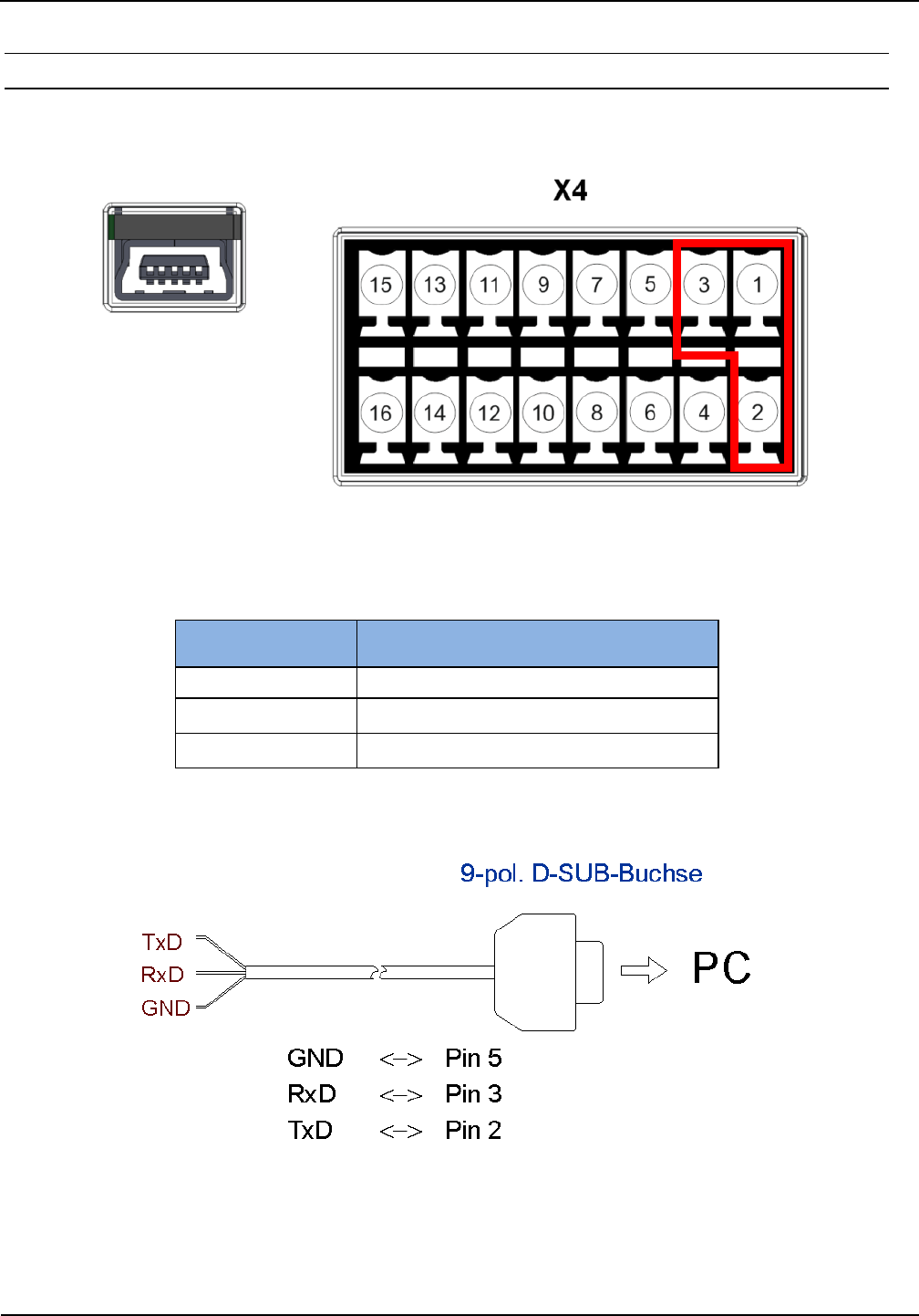
4.3.3. RS232 Interface on connector X4
The RS232 interface is connected on X4. The transmission parameters can be configured by
means of software protocol.
Figure 7: RS232 interface pin-outs on X4
Table 7: Pin Assignment RS232 Interface
Pin Number
at Connector X4
Pin Assignment
1
RS232 – RxD
2
RS232 – TxD
3
GND
Figure 8: Wiring example for connecting the RS232 interface to a 9 pin D-SUB plug
IDENTIFICATION
Installation
ID ISC.LRU1002
FEIG ELECTRONIC GmbH
Page 16 of 32
M61110-2e-ID-B.docx
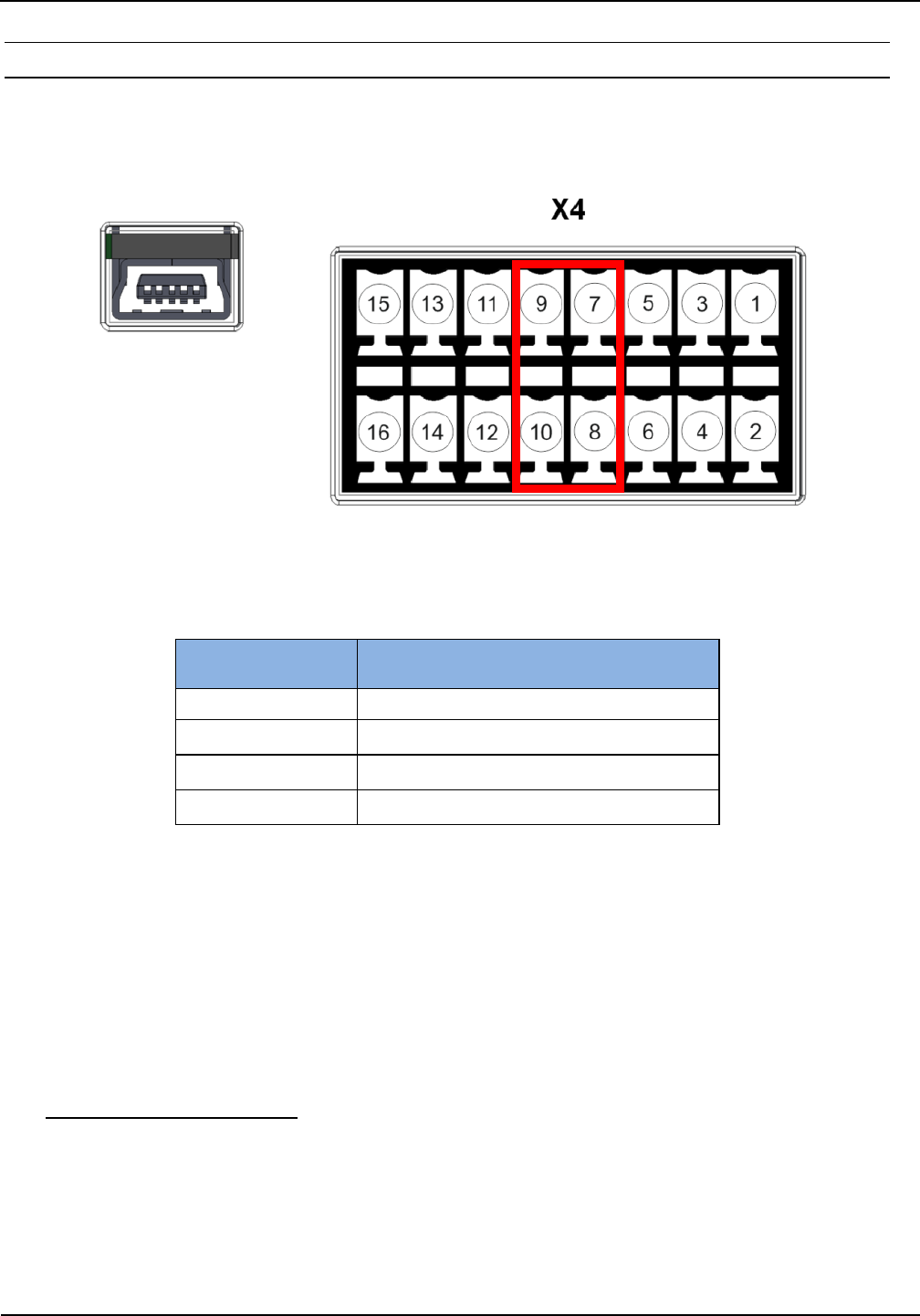
4.3.4. Data-Clock Interface on connector X4
The connection of the data-clock interface takes place via the digital Outputs OUT1 and OUT2 at
connector X4. The wire for the clock (Data-0) needs to be connected to connector OUT1-E, the
wire for the data (Data-1) needs to be connected to connector OUT2-E.
Figure 9: Data-Clock Interface on connector X4
Table 8: Pin Assignment Data/Clock Interface
Pin Number
at Connector X4
Pin Assignment
7
Clock / Data-0
8
Vcc
9
Data / Data-1
10
Vcc
NOTE:
The data-clock interface is only available in Scan-Mode.
The data-clock interface cannot be used to configure the reader.
The digital outputs OUT1 and OUT2 are not available, if the data-clock interface is activated.
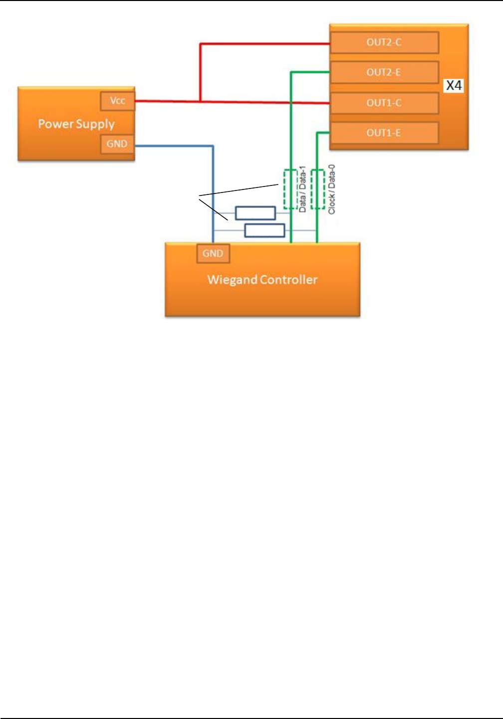
The data as well as the clock need to be supplied with an external voltage. The output is
designed for max. 24 V DC / 20 mA.
For access control application it is possible to connect the reader parallel with two inputs of
a Wiegand controller. By that it is possible to control two traffic lanes (e.g. Entrance and
Exit). Please read the application note N61011-xe-ID-B for more details.
IDENTIFICATION
Installation
ID ISC.LRU1002
FEIG ELECTRONIC GmbH
Page 17 of 32
M61110-2e-ID-B.docx
Figure 10: Wiring Example
NOTE:
Please consider possible limitations of the Wiegand Controller regarding the used supply
voltage.
The necessity of the external pull down resistor is depending on the inner circuit of the
used Wiegand Controller
In dependency on the inner circuit of the used Wiegand Controller it is necessary to use
external serial resistors to limit the current on the data and clock wires.
See Notes below for
resistor values
IDENTIFICATION
Installation
ID ISC.LRU1002
FEIG ELECTRONIC GmbH
Page 18 of 32
M61110-2e-ID-B.docx
4.4. Inputs and Outputs on connector X4
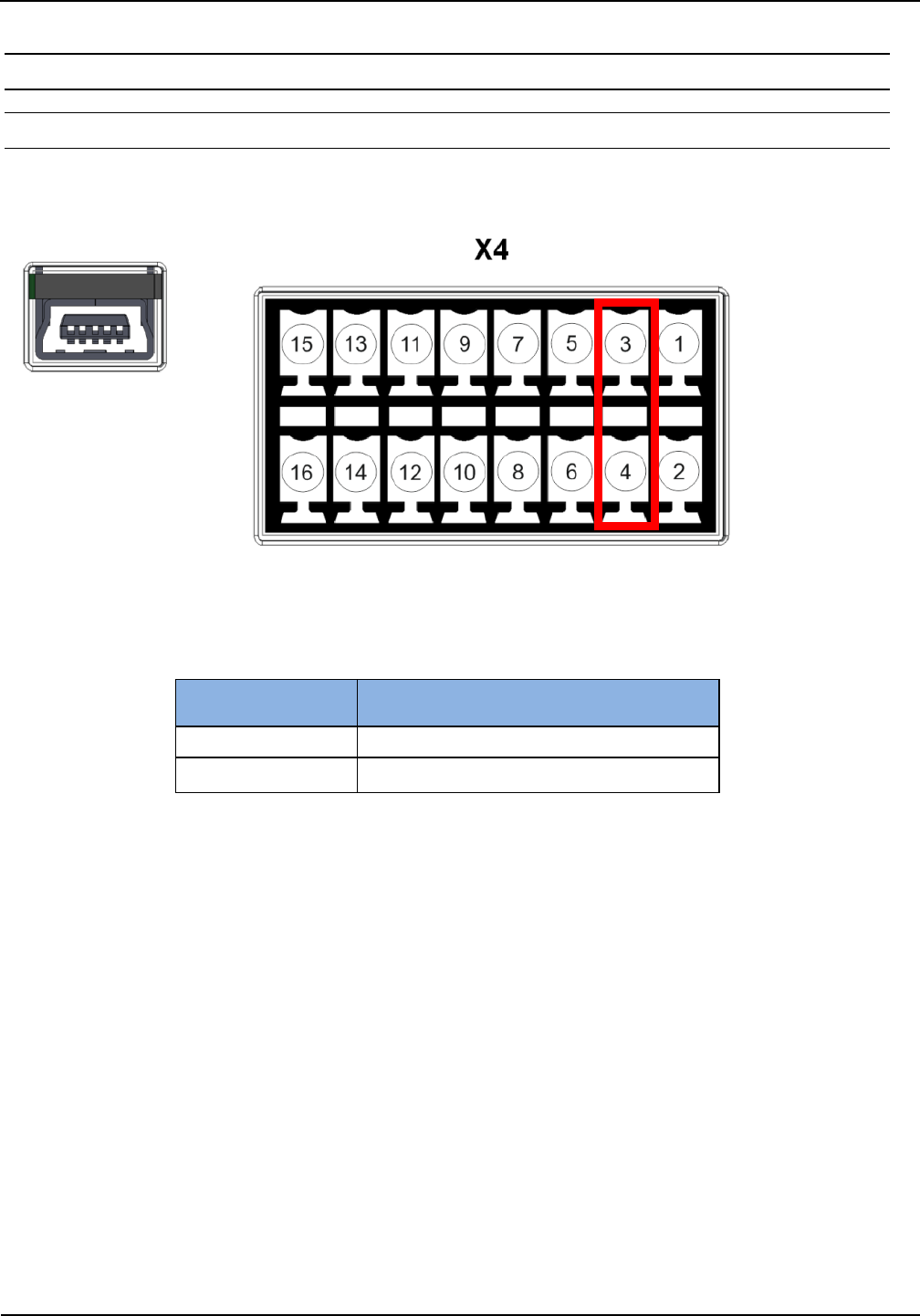
4.4.1. 24 V DC voltage on connector X4
A 24 V DC voltage can be received on Pin 4 of connector X4. It can be used e.g. to drive the digital
Inputs and Outputs of the reader.
Figure 11: 24 V DC Voltage
Table 9: Pin Assignment 24 V DC Voltage
Pin Number
at Connector X4
Pin Assignment
3
GND
4
24 V DC
CAUTION:
The maximum current is limited to 750 mA.
IDENTIFICATION
Installation
ID ISC.LRU1002
FEIG ELECTRONIC GmbH
Page 19 of 32
M61110-2e-ID-B.docx
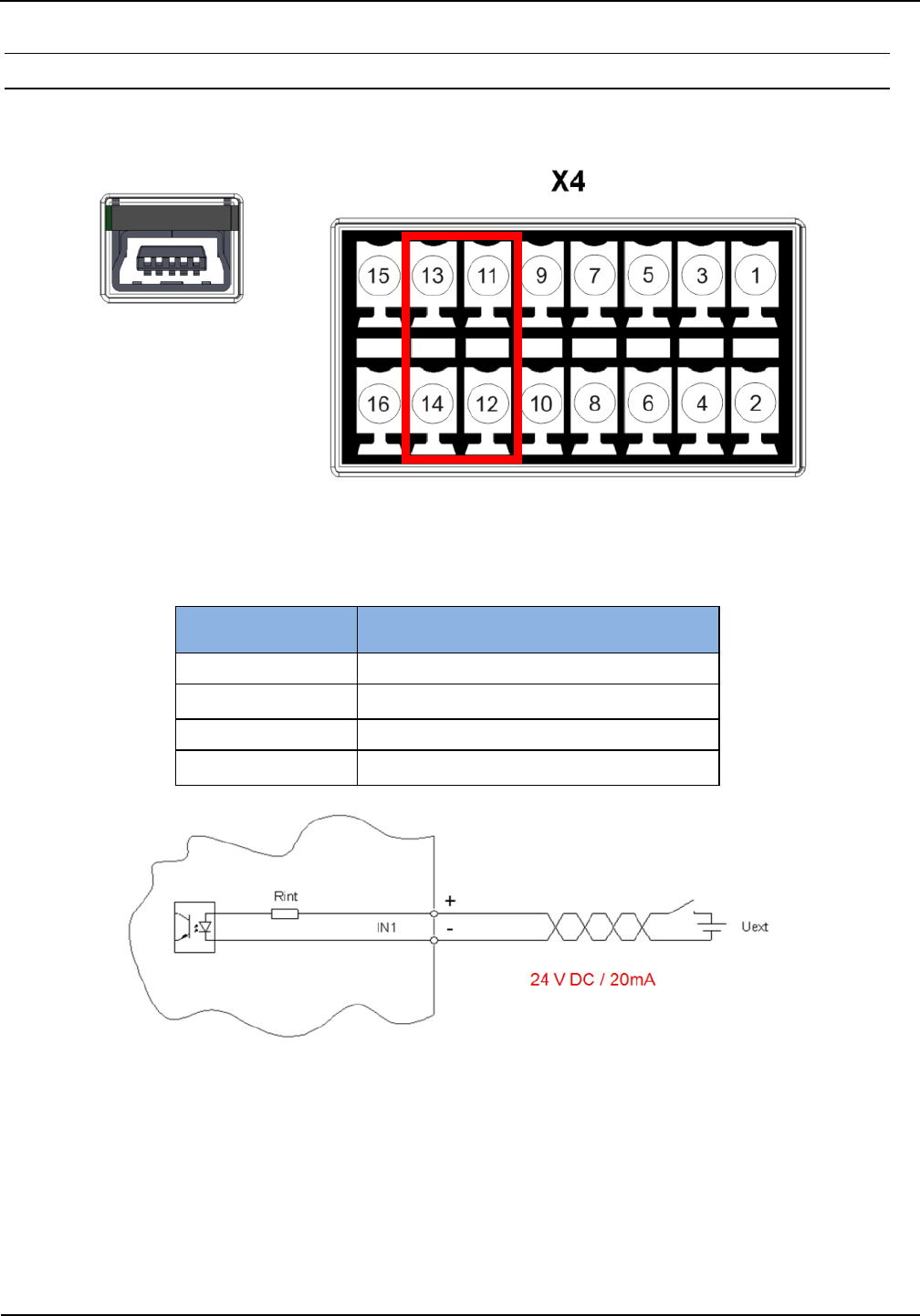
4.4.2. Digital Inputs on connector X4
The optocouplers on Terminal X4 are galvanically isolated from the Reader electronics and must
therefore be externally supplied.
Figure 12: Digital inputs IN1 / IN2
Table 10: Pin Assignment digital Inputs IN1 / IN2
Pin Number
at Connector X4
Pin Assignment
11
IN1 -
12
IN1 +
13
IN2 -
14
IN2 +
Figure 13: Internal and external wiring of the digital inputs IN1 / IN2
NOTE:
The inputs are configured for a maximum input voltage of 24 V DC and an input current of
max. 20 mA.
Polarity reversal or overload on the input will destroy it.
IDENTIFICATION
Installation
ID ISC.LRU1002
FEIG ELECTRONIC GmbH
Page 20 of 32
M61110-2e-ID-B.docx
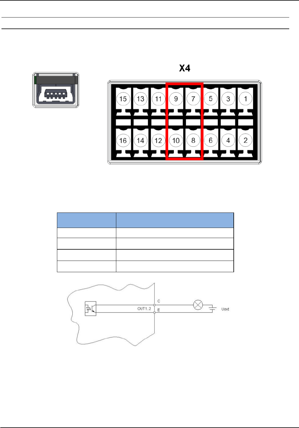
4.4.3. Digital outputs on connector X4
The transistor connections, collector and emitter, of the optocoupler output are galvanically isolated
from the Reader electronics and are carried to the outside without any internal ancillary circuitry on
Terminal X4. The output must therefore be powered by an external power supply.
Figure 14: Digital outputs OUT1 / OUT2
Table 11: Pin Assignment digital outputs OUT1 / OUT2
Figure 15: Internal and external wiring of the digital outputs OUT1 / OUT2
CAUTION:
The output is configured for max. 24 V DC / 20 mA.
Polarity reversal or overload on the output will destroy it.
The output is intended for switching resistive loads only.
Pin Number
at Connector X4
Pin Assignment
7
OUT1-E
8
OUT1-C
9
OUT2-E
10
OUT2-C
IDENTIFICATION
Installation
ID ISC.LRU1002
FEIG ELECTRONIC GmbH
Page 21 of 32
M61110-2e-ID-B.docx
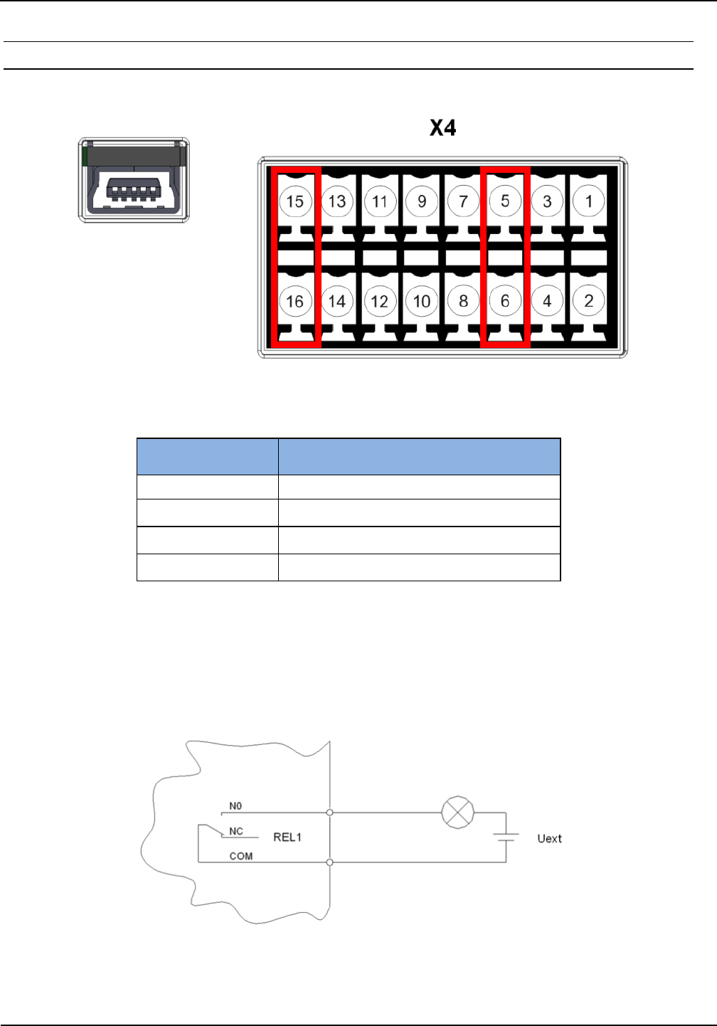
4.4.4. Relay output on connector X4
There are 2 relay outputs (normally open) available on connector X4.
Figure 16: Relay outputs REL1 / REL2
Table 12: Pin Assignment Relay Outputs REL1 / REL2
CAUTION:
The relay outputs are configured for max. 24 V DC / 2 A constant load.
The switching current must not exceed 1A.
The relay outputs are intended for switching resistive loads only. If an inductive load is
connected, the relay contacts must be protected by means of an external protection circuit.
Figure 17: External wiring of the relay outputs
Pin Number
at Connector X4
Pin Assignment
5
REL1-NO
6
REL1-COM
15
REL2-NO
16
REL2-COM
IDENTIFICATION
Installation
ID ISC.LRU1002
FEIG ELECTRONIC GmbH
Page 22 of 32
M61110-2e-ID-B.docx
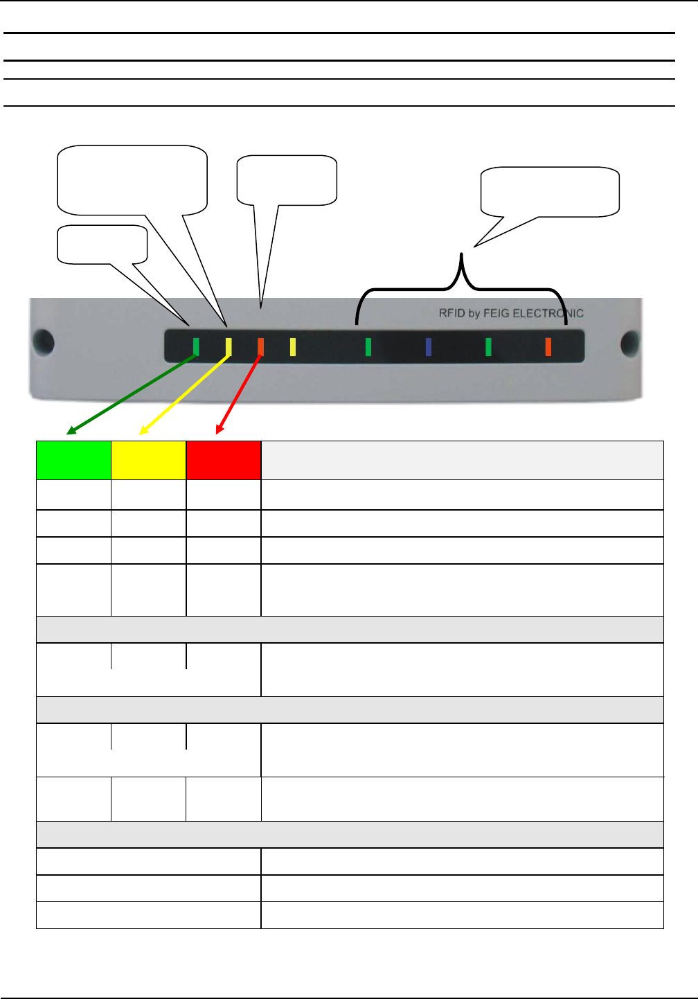
5. Operating and Display Elements
5.1. Status LED
Table 13: Configuration of the LED
Green
Yellow
Red
Description
FLASH
-
OFF
Normal Reader operation
FLASH
FLASH
OFF
Reader receives a valid protocol from host
FLASH
-
ON
RF Warning [0x84]
FLASH
(alternat-
ing)
-
FLASH
(alternat-
ing)
Hardware Warning; perform Reader Diagnostic [0x6E] for
further information
Firmware Update:
FLASH
FLASH
FLASH
Firmware transfer from host to reader
(Please do not switch off the reader or disconnect the interface cable)
(light in sequence)
Configurations-Reset:
FLASH
FLASH
FLASH
While T1 is pushed and hold for maximal 5 s
(light in sequence)
ON
ON
ON
After T1 has been pushed and hold for 5 s complete con-
figuration reset has been performed
ANT 1 – 4:
Green
HF Power switched on
Blue
Transponder detected
Red
Antenna impedance error (unequal 50 Ohm)
Antenna 1- 4
RUN
Host
Communication
Warning
IDENTIFICATION
Installation
ID ISC.LRU1002
FEIG ELECTRONIC GmbH
Page 23 of 32
M61110-2e-ID-B.docx
5.2. Reset Push Button T1
By means of the push button T1 a complete configuration reset can be performed. The push button
is positioned in the middle between the antenna connectors ANT3 and ANT4. Figure 18 shows the
position of the push button. It is located inside the reader housing. To press the reset button T1
you should use a paper clip.
To reset the reader back to factory default push the button for at least 5 s until the 3 status LED
(left side) are switched on continuously. After releasing the push button the reader performs a re-
start.
During a complete configuration reset all parameters of the reader will be reset back to factory de-
fault and need to be configured again.
Figure 18: Position of the reset button T1
IDENTIFICATION
Installation
ID ISC.LRU1002
FEIG ELECTRONIC GmbH
Page 24 of 32
M61110-2e-ID-B.docx
5.3. Reader Power Adjustment
To achieve the optimum reading performance it is necessary to set the reader output power to the
highest allowed value. This depends on the used reader type (EU / FCC) and the regulation in the
country were the reader is used.
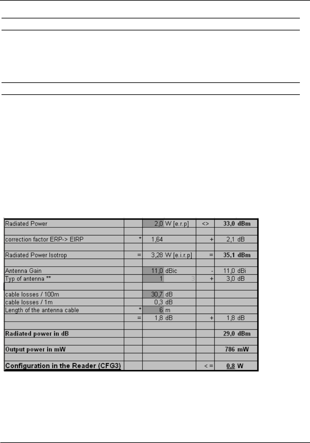
5.3.1. EU reader according to EN 302 208
According to the standard EN 302 208 the maximum radiated power is 2 W e.r.p. (Effective Radi-
ated Power) in countries of the European Union. The in the reader configured output power Pout
depends on the antenna gain in dBi and the attenuation of the antenna cable. If a circular polarized
antenna is used the antenna gain [dBic] can be reduced by 3dB. At a linear polarized antenna the
maximum linear antenna gain [dBi] must be used.
POut = Perp - Antenna Gain + Cable loss + 2,1dB**
** Correction Factor to convert the radiated power from e.r.p to e.i.r.p.
For the calculation of the reader output power POut an Excel file „Calc-RF-Power.xls“ can be used.
Available from Feig Electronic GmbH.
Example:
** linear antenna = „0“, circular antenna = „1“
Figure 19: Calculation of the output power
In Figure 19 the allowed antenna power is shown for the use of the FEIG standard antenna
ANT.U600/270 –EU and a 6m long Belden H155 coaxial cable.

IDENTIFICATION
Installation
ID ISC.LRU1002
FEIG ELECTRONIC GmbH
Page 25 of 32
M61110-2e-ID-B.docx
5.3.2. FCC Reader according to FCC 47 Part 15
According to the FCC approval, Title 47, Part15 the maximum output power of the reader is limited
to 1 W (30dBm). The maximum radiated power of the antenna should not increase more than 4 W
e.i.r.p. Due to these facts the antenna ID ISC.ANT.U600/270-FCC (7,5 dBi) must be used with at
least 5,0 m of cable type Belden H155 (0,3 dB/m) or at least 3,0 m of cable type RG58 (0,5 dB/m).
Antenna Type
Permitted Cable
ID ISC.ANT.U600/270-FCC
Min. 5,0 m of cable type Belden H155 (0,3 dB/m) or
min. 3,0 m of cable type RG58 (0,5 dB/m)
ID ISC.ANT.U270/270-FCC
-/-
IDENTIFICATION
Installation
ID ISC.LRU1002
FEIG ELECTRONIC GmbH
Page 26 of 32
M61110-2e-ID-B.docx
6. Technical Data
MECHANICAL DATA
Housing
Aluminum powder-coated
Dimension (W x H x D)
260 mm x 157 mm x 68 mm
10.2 inch x 6.2 inch x 2.7 inch
Weight
1,8 kg (4.0 lb)
Protection Class
IP 43 (with protection cap IP64)
Colour
RAL 9003 (Signal White)
ELECTRICAL DATA
Power Supply
24 V DC ± 20 % (Noise Ripple: max. 150 mV)
Current Consumption
max. 3,8 A
typ.* 1,0 A
*without the power consumption of an external connected
device, like a UHF –Multiplexer
Operating Frequency
EU-Reader
FCC-Reader
865 MHz to 868 MHz (EN 302 208)
902 MHz to 928 MHz (FCC47 Part15)
RF-Power
100 mW up to max. 2 W configurable
(Tolerance: max. ±3 dB)
Antenna Connection
4 x SMA female (50 ), internal Multiplexer,
configurable with 24 V DC / max. 500 mA
on the antenna output
RF-Diagnostic
RF-Channel monitoring
Antenna SWR-monitoring
Internal Overheating control*
Outputs
2 x Optocoupler
2 x Relay (NOC)
24 V DC / 20 mA (galvanically isolated)
24 V DC / 1 A (switching current), (2A con-
stant load)
Inputs
2 x Optocoupler
max.24 V DC / 20 mA
* Caution: Overheating of the device may result in performance losses. It is recommended to activate the RF of the
reader only if there is a transponder in the detection range of an antenna.

IDENTIFICATION
Installation
ID ISC.LRU1002
FEIG ELECTRONIC GmbH
Page 27 of 32
M61110-2e-ID-B.docx
Interfaces
RS232
USB Mini (USB 2.0; Full Speed; On-The-Go)
Ethernet (10/100 BASE-T; MDI/MDI-X cross
over detection; IPv4)
Wiegand (Scan Mode Schnittstelle)
FUNCTIONAL PROPERTIES
Protocol Modes
FEIG ISO HOST Mode (Advanced Protocol
Frame)
Buffered Read Mode
Scan Mode
Notification Mode
Automatic Data
Buffering and
Filtering
Supported Transponder Types
EPC Class 1 Generation 2
ISO 18000-6-C (Upgrade Code required)
Further transponder types on request possible
Optical Indicators
16 LEDs for analyze the operating status and
the connected antennas
Further Features
Anticollision
Output of RSSI and Phase Angle
RF-Channel monitoring
Support of enciphered transponder communica-
tion
Secure key memory
“Config Cloning“-function
Real-time clock (Battery-buffered)
AMBIENT CONDITIONS
Temperature Range
Operation
Storage
-25 °C up to +55 °C
-25 °C up to +85 °C
Humidity
5 % up to 95 % non-condensing
Vibration
EN 60068-2-6
10 Hz to 150 Hz: 0,075 mm / 1 g
Shock
EN 60068-2-27
Acceleration 30 g

IDENTIFICATION
Installation
ID ISC.LRU1002
FEIG ELECTRONIC GmbH
Page 28 of 32
M61110-2e-ID-B.docx
APPLICABLE STANDARDS
Radio Regulation
Europe
USA
Canada
EN 302 208
FCC 47 CFR Part 15
IC RSS-210
EMC
EN 301 489
Safety
Low Voltage
Human Exposure
EN 62368-1
EN 50364
IDENTIFICATION
Installation
ID ISC.LRU1002
FEIG ELECTRONIC GmbH
Page 29 of 32
M61110-2e-ID-B.docx
7. Radio Approvals
7.1. Europe (CE)
Hereby, FEIG ELECTRONIC GmbH declares that the radio equipment type ID ISC.LRU1002 is in
compliance with Directive 2014/53/EU.
The full text of the EU declaration of conformity is available at the following internet address:
http://www.feig.de/en/downloads-support/declarations-of-conformity.html
Performance Classification according to ETSI EN 301 489: Class 2

IDENTIFICATION
Installation
ID ISC.LRU1002
FEIG ELECTRONIC GmbH
Page 30 of 32
M61110-2e-ID-B.docx
7.2. USA (FCC) and Canada (IC)
7.2.1. USA (FCC) and Canada (IC) warning notices
Product name:
ID ISC.LRU1002-FCC
FCC ID:
IC:
PJMLRU1002A
6633A-LRU1002A
Notice for USA and
Canada
This device complies with Part 15 of the FCC Rules and with
RSS-210 of Industry Canada.
Operation is subject to the following two conditions.
(1) this device may not cause harmful interference, and
(2) this device must accept any interference received,
including interference that may cause undesired operation.
Unauthorized modifications may void the authority granted under Federal
communications Commission Rules permitting the operation of this device.
This equipment has been tested and found to comply with the limits for a
Class A digital device, pursuant to Part 15 of the FCC Rules. These limits are
designed to provide reasonable protection against harmful interference when
the equipment is operated in a commercial environment. This equipment
generates, uses, and can radiate radio frequency energy and, if not installed
and used in accordance with the instruction manual, may cause harmful
interference to radio communications. Operation of this equipment in a
residential area is likely to cause harmful interference in which case the user
will be required to correct the interference at his own expense.
Le présent appareil est conforme aux CNR d'Industrie Canada applicables
aux appareils radio exempts de licence. L'exploitation est autorisée aux deux
conditions suivantes :
(1) l'appareil ne doit pas produire de brouillage, et
(2) l'utilisateur de l'appareil doit accepter tout brouillage radioélectrique subi,
même si le brouillage est susceptible d'en compromettre le fonctionnement.
Warning:
Changes or modification made to this equipment not expressly approved by
FEIG ELECTRONIC GmbH may void the FCC authorization to operate this equipment.

IDENTIFICATION
Installation
ID ISC.LRU1002
FEIG ELECTRONIC GmbH
Page 31 of 32
M61110-2e-ID-B.docx
7.2.2. Label Information
The following information must be placed at the outer side of the housing in which the reader is
mounted.
Contains FCC ID PJMLRU1002A
Contains IC: 6633A-LRU1002A
7.2.3. Installation with FCC / IC Approval
FCC-/IC-NOTICE: To comply with FCC Part 15 Rules in the United States / with IC Radio Stan-
dards in Canada, the system must be professionally installed to ensure compliance with the Part
15 certification / IC certification. It is the responsibility of the operator and professional installer to
ensure that only certified systems are deployed in the United States / Canada.
7.2.4. USA (FCC) and Canada (IC) approved antennas
This radio transmitter (identify the device by certification number, or model number if Category II)
has been approved by Industry Canada to operate with the antenna types listed below with maxi-
mum permission gain and required antenna impedance for each antenna type indicated. Antenna
types, not included in this list, having a gain greater than the maximum gain indicated for that type,
are strictly prohibited for use with this device.
The antennas used for this transmitter must be installed to provide a separation distance of at least
34 cm from all persons and must not be located or operating in conjunction with any other antenna
or transmitter, except as listed for this product's certification.
Le présent émetteur radio (identifier le dispositif par son numéro de certification ou son numéro de
modèle s’il fait partie du matériel de catégorie I) a été approuvé par Industrie Canada pour fonc-
tionner avec les types d’antenne ’énoncé ci-dessus et ayant un gain admissible maximal et
l’impédance requise pour chaque type d’antenne. Les types d’antenne non inclus dans cette liste,
ou dont le gain est supérieur au gain maximal indiqué, sont strictement interdits pour l’exploitation
de l’émetteur.
Les antennes utilisées pour cet émetteur doit être installé pour fournir une distance de séparation
d'au moins 34 cm de toutes les personnes et ne doit pas être situé ou opérant en conjonction avec
une autre antenne ou un autre émetteur, sauf dans les cas énumérés à la certification de ce pro-
duit.
Following antennas are approved by FCC according FCC Part 15 and IC Canada according
RS210
ID ISC.ANT.U270/270-FCC (6.0 dBi)
ID ISC.ANT.U600/270-FCC (7,5 dBi)
IDENTIFICATION
Installation
ID ISC.LRU1002
FEIG ELECTRONIC GmbH
Page 32 of 32
M61110-2e-ID-B.docx
ANNEX A - Accessories
Following optional accessories are available:
Order No.
Article
Description
3558.000.00
ID ISC.LR.CSC-IP64
Connector Sealing Cap
Plastic Sealing Cap for Reader Connectors with Steel Conduit
Pipe Thread (PG) for ID ISC.LRU3x00 and ID ISC.LRU1002
3831.000.00
ID ISC.LRU3x00-MS
Mounting Rail Set
Mounting Rail Set for ID ISC.LRU3x00 and ID ISC.LRU1002
EU: 3198.000.00
ID ISC.ANT.U600/270
UHF Antenna
UHF Antenna for connection to UHF Reader, Connector: RG58
coax cable 10 cm, plug SMA – female, 3dB beamwidth 65° x
30°
FCC: 3685.000.00
EU: 3199.000.00
ID ISC.ANT.U270/270
UHF Antenna
UHF Antenna for connection to UHF Reader, Connector: SMA
– female, 3dB beamwidth 65° x 65°
FCC: 3686.000.00
EU: 3200.000.00
ID ISC.ANT.U170/170
UHF Antenna
UHF Antenna for connection to UHF Reader, Connector:
RG316/U coax cable 10 cm, plug SMA – female, 3dB beam-
width 85° x 85°
3308.000.00
ID ISC.ANT.U600/270-MS
Mounting Set Antenna UHF
Mounting Set for UHF Antenna ID ISC.ANT.U600/270. Suitable
for mounting on installation pipes with a diameter of up to 60
mm.
3309.000.00
ID ISC.ANT.U270/270-MS
Mounting Set Antenna UHF
Mounting Set for UHF Antenna ID ISC.ANT.U270/270. Suitable
for mounting on installation pipes with a diameter of up to 60
mm.
3310.000.00
ID ISC.ANT.U170/170-MS
Mounting Set Antenna UHF
Mounting Set for UHF Antenna ID ISC.ANT.U170/170. Suitable
for mounting on installation pipes with a diameter of up to 60
mm.
1654.002.00
ID ISC.ANT.C2-A UHF
Antenna Cable 2m
H155 Coax Cable for UHF Reader, Connection Plug SMA -
male/male, Length: approx. 2 m
1654.003.00
ID ISC.ANT.C6-A UHF
Antenna Cable 6m
H155 Coax Cable for UHF Reader, Connection Plug SMA -
male/male, Length: approx. 6 m
2557.000.00
ID NET.24V-B
Power Supply Unit
Power Supply Unit for ID ISC.LR/LRM2500/1002, ID
ISC.LRU/LRU3x00/1002. Versatile outlets available (EU, GB,
US - not included).
2558.000.00
ID CAB.NET.24V-B-EU
Cable with European Plug
Cable with Continental European Plug for Power Supply Unit ID
NET.24V-B
2559.000.00
ID CAB.NET.24V-B-GB
Cable with GB/UK Plug
Cable with GB Plug for Power Supply Unit ID NET.24V-B
2560.000.00
ID CAB.NET.24V-B-US
Cable with US Plug
Cable with US Plug for Power Supply Unit ID NET.24V-B
4104.000.00
ID CPR.USB/OTG
USB Stick + On-The-Go
Adapter Cable
4 GB USB Flash Drive incl. USB On-The-Go Adapter Cable