Feig Electronic MR101-PR101 Inductive Reader User Manual M50300 1de ID B neu
Feig Electronic GmbH Inductive Reader M50300 1de ID B neu
Users Manual
INSTALLATION
public (B)
2005-06-02
M50300-1de-ID-B-neu.doc
ID ISC.MR101-USB
ID ISC.PR101-USB
(english)

OBID i-scanInstallation ID ISC.PR / MR101-USB
FEIG ELECTRONIC GmbH Page 2of 14 M50300-1de-ID-B-neu.doc
ENGLISH
Note
Copyright 2005 by
FEIG ELECTRONIC GmbH
Lange Strasse 4
D-35781 Weilburg-Waldhausen
Tel.: +49 6471 3109-0
http://www.feig.de
With the edition of this document, all previous editions become void. Indications made in this man-
ual may be changed without previous notice.
Copying of this document, and giving it to others and the use or communication of the
contents thereof are forbidden without express authority. Offenders are liable to the pay-
ment of damages. All rights are reserved in the event of the grant of a patent or the regis-
tration of a utility model or design.
Composition of the information in this manual has been done to the best of our knowledge. FEIG
ELECTRONIC GmbH does not guarantee the correctness and completeness of the details given
in this manual and may not be held liable for damages ensuing from incorrect or incomplete infor-
mation. Since, despite all our efforts, errors may not be completely avoided, we are always grateful
for your useful tips.
The installation instructions given in this manual are based on advantageous boundary conditions.
FEIG ELECTRONIC GmbH does not give any guarantee promise for perfect function in cross en-
vironments.
FEIG ELECTRONIC GmbH assumes no responsibility for the use of any information contained in
this manual and makes no representation that they free of patent infringement. FEIG
ELECTRONIC GmbH does not convey any license under its patent rights nor the rights of others.
OBID®and OBID i-scan®are registered trademarks of FEIG ELECTRONIC GmbH.
I-CODE®is a registered trademark of Philips Electronics N.V.
Tag-itTM is a registered trademark of Texas Instruments Incorporated.

OBID i-scanInstallation ID ISC.PR / MR101-USB
FEIG ELECTRONIC GmbH Page 3of 14 M50300-1de-ID-B-neu.doc
ENGLISH
Contents
1. Safety instructions / Warning - read before start-up !.........................................................4
2. Performance features of the readers....................................................................................5
2.1. Performance features .....................................................................................................5
2.2. Available reader-types....................................................................................................5
3. Assembly and wiring .............................................................................................................6
3.1. Connector sockets..........................................................................................................6
3.2. USB-Interface connection X3.........................................................................................7
3.3. Power supply (only ID ISC.MR101) ................................................................................7
3.4. Antenna terminal X4 (only ID ISC.MR101) .....................................................................8
3.5. Starting ............................................................................................................................9
3.5.1. ID ISC.MR101 ...............................................................................................................9
3.5.2. ID ISC.PR101................................................................................................................9
4. Control and display elements .............................................................................................10
4.1. LED.................................................................................................................................10
5. Technical data......................................................................................................................11
6. Approvals..............................................................................................................................13
6.2. USA (FCC)....................................................................................................................13
6.2. Europe (CE) .................................................................................................................13
7. Appendix...............................................................................................................................14
7.1. Accessories...................................................................................................................14
7.1.1. Wall mounting kit ID ISC.MS.MR/PR-A .......................................................................14

OBID i-scanInstallation ID ISC.PR / MR101-USB
FEIG ELECTRONIC GmbH Page 4of 14 M50300-1de-ID-B-neu.doc
ENGLISH
1. Safety instructions / Warning - read before start-up !
•The device has to be used only for the purpose designed by the manufacturer.
•The operation manual has to be stored available at any time and has to be handed over to
each user.
•Unauthorized changes and the use of spare parts and additional devices which have not been
sold or recommended by the manufacturer may cause fire, electric shocks or injuries. Such
measures will lead to exclusion of any liability by the manufacturer.
•The liability-prescriptions of the manufacturer in the issue valid at the time of purchase are
valid for the device. The manufacturer is not legally responsible for incorrect, unsuitable
manual or automatical setting of parameters for a device or the incorrect application of a
device.
•Repairs can only be executed by the manufacturer.
•Installation-, operation- and maintenance procedures should only be carried out by qualified
personnel.
•Before opening the device, the power supply must always be interrupted. Make sure that the
device is without voltage by measuring. CAUTION! The fading of an operation control (LED) is
no indicator for an interrupted power supply or the device being without voltage!
•Works at the device and its installation have to be executed according to the national legal
requirements and local prescriptions.
•When working on devices the valid safety regulations must be observed
•Special advice for carriers of cardiac pacemakers:
Although this device doesn't exceed the valid limits for electromagnetic fields you should keep
a minimum distance of 25 cm between the device and your cardiac pacemaker and not stay in
an immediate proximity of the device respective the antenna for some time.

OBID i-scanInstallation ID ISC.PR / MR101-USB
FEIG ELECTRONIC GmbH Page 5of 14 M50300-1de-ID-B-neu.doc
ENGLISH
2. Performance features of the readers
2.1. Performance features
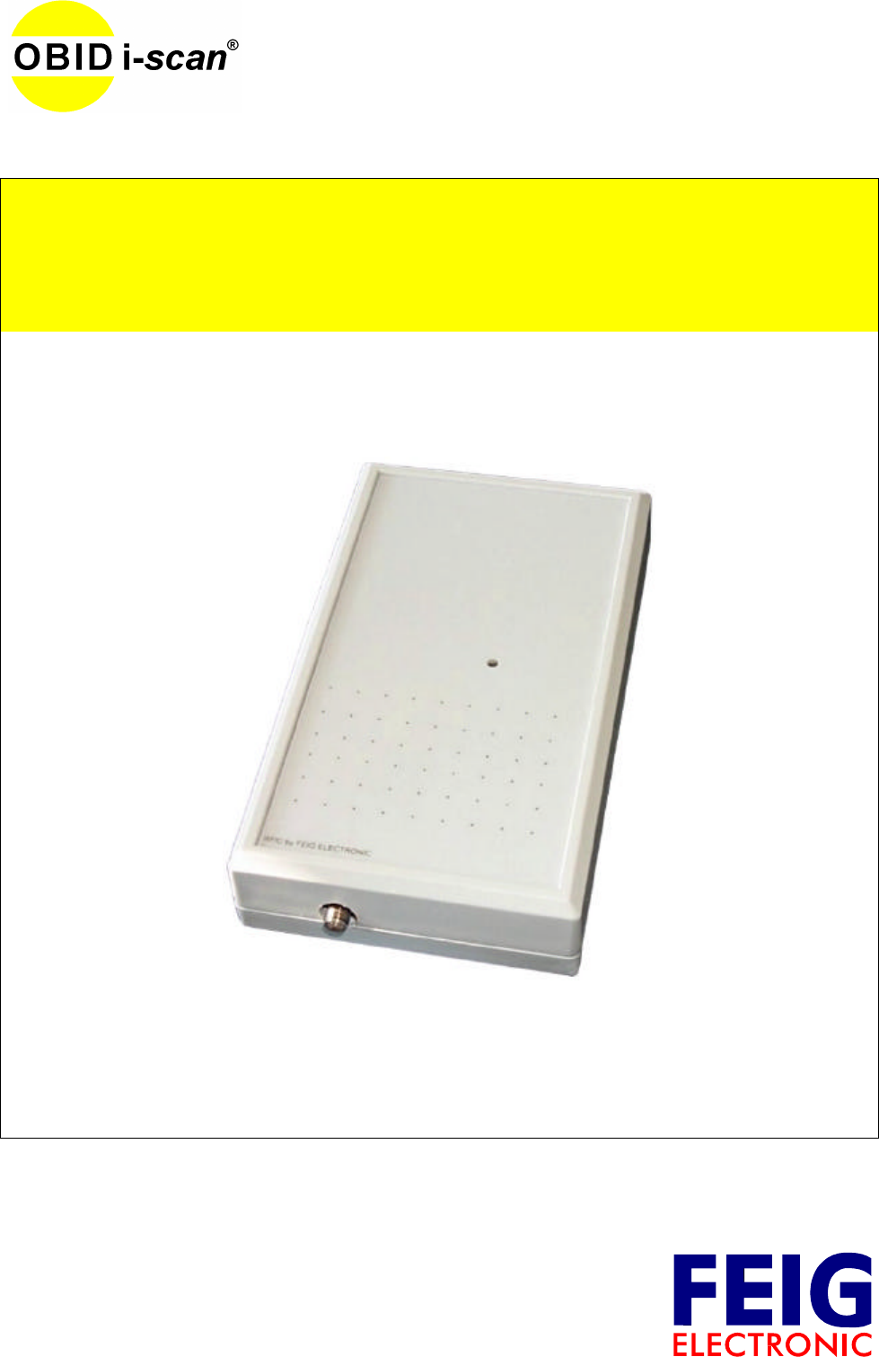
The readers are designed for reading passive data carriers, so-called „Smart Labels“ at an oper-
ating frequency of 13.56 MHz.
The reader ID ISC.MR101 is suitable for all applications in which moderate reading distances are
required. Also required is an external antenna connected to the reader.
The ID ISC.PR101 is suitable for all applications which don’t require wide reader ranges. The
reader contains of an internal antenna, so that is no external antenna necessary.
An anticollision function enables simultaneous reading of up to 30 transponders per second.
The reader electronics of the readers is contained in a plastic housing having an IP30 enclosure
rating. Both readers comes with an USB-Interface.
The reader ID ISC.PR101 will be powered via the USB-Interface. An additional power supply is not
necessary.
2.2. Available reader-types
Following reader-Types are available at present:
Reader-Types Description
ID ISC.MR101-USB USB-Interface and external antenna
ID ISC.PR101-USB USB-Interface and internal antenna
Table 1: Reader-Types
OBID i-scanInstallation ID ISC.PR / MR101-USB
FEIG ELECTRONIC GmbH Page 6of 14 M50300-1de-ID-B-neu.doc
ENGLISH
3. Assembly and wiring
The readers are designed for an office environment. They can be wall-mounted, in this case the
wall-mount kit should be ordered separately.
(see Appendix: Accessories and Wall mounting kit ID ISC.MS.MR/PR-A)
Notes:
•The distance between two active antennas should not fall below 4m.
•Before any installation the intended position of the reader should be tested for its suit-
ability.
•Only ID ISC.PR101:
The reader should not be installed directly upon conductive materials as e.g. metal sur-
faces, metal grids (reinforcements) or metallized surfaces, as these surfaces reduce the
detection range of the reader. The distance between the reader and such surfaces
should be min. 10 cm.
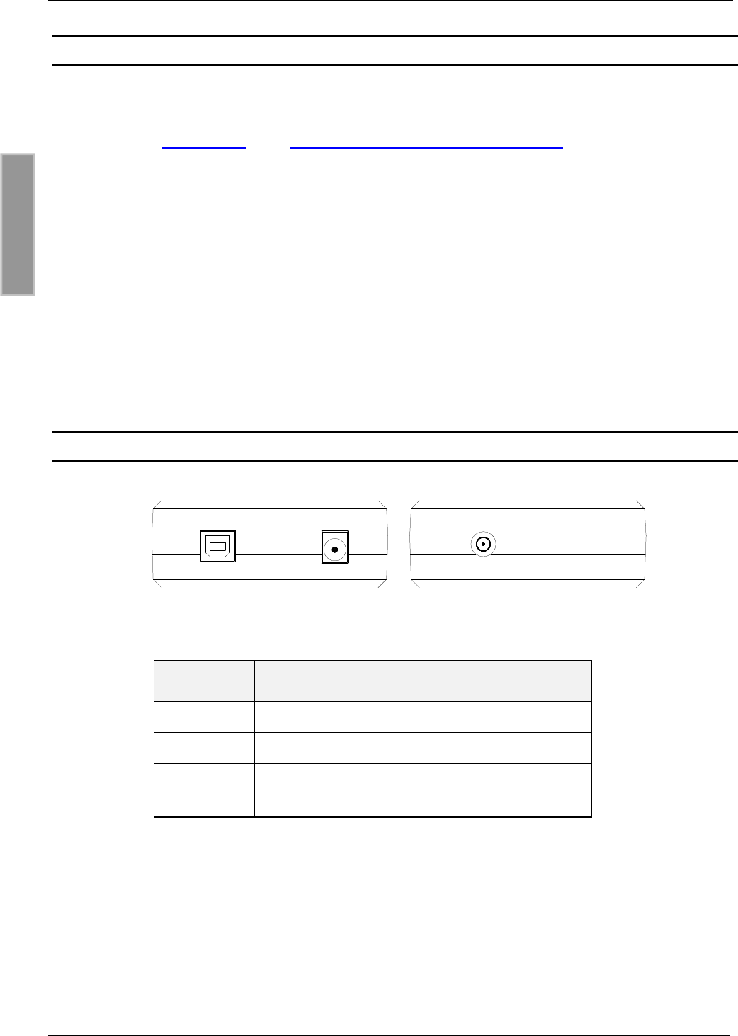
3.1. Connector sockets
Fig. 1: Connector sockets
Sockets Description
X1 Power supply
X3 USB-plug
X4 Connection of the external antenna
(direct impedance 50Ω)
Table 2: Connection sockets
X1X3 X4
OBID i-scanInstallation ID ISC.PR / MR101-USB
FEIG ELECTRONIC GmbH Page 7of 14 M50300-1de-ID-B-neu.doc
ENGLISH
3.2. USB-Interface connection X3
There is a USB-socket on board for the connection of the USB-Interface. The pinout is standard-
ized. The datarate is reduced to 12 Mbit (USB full speed). A standard USB-cable can be used.
The length of the USB-cable can be a max. of 5 meter. It isn’t allowed to use longer cables!
A serial data cable with integrated power connection is available for the reader.
(see Accessories).
Feig Article No. Part No.
1690.000.00 ID CAB.RS-A
Table 3: Serial data cable
The reader ID ISC.PR101-USB does not need an external power supply. The power supply takes
place via the USB-Interface (Bus-powered). The USB-Interface must support a current of about
500mA (High Powered Hub).
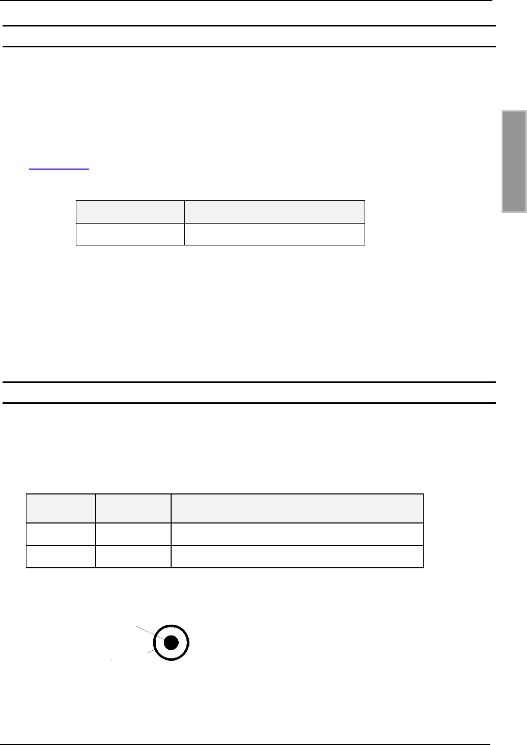
3.3. Power supply (only ID ISC.MR101)
Connect the 12 V DC supply voltage to socket X1 on the circuit board.
Note:
Reversing the polarity of the supply voltage may destroy the device.
Terminal Name Description
X1 / inside +12V + 12 V DC – supply voltage
X1 / outside AGND Ground – supply voltage
Table 4: Connecting the supply voltage
Fig. 2: DC socket configuration
+ 12 V DC
AGND
OBID i-scanInstallation ID ISC.PR / MR101-USB
FEIG ELECTRONIC GmbH Page 8of 14 M50300-1de-ID-B-neu.doc
ENGLISH
Power supply recommendations :
To take full advantage of the reader performance, you must use a sufficiently regulated and noise-
free power supply. Preferred is a linear power supply with 12V DC / 580 mA. When using a
switching power supply, be sure that its internal switching frequency is less than 300 kHz.
(see: Accessories).
Feig Artikel Nr. Bezeichnung Bezeichnung
1688.001.00 ID NET.12V-B 12 V DC Netzteil
Eingangsspannung 95 - 265V AC
Table 5: Recommended power supply
Note: The power supply is delivered with a DC plug 2.5mm x 5.5mm.
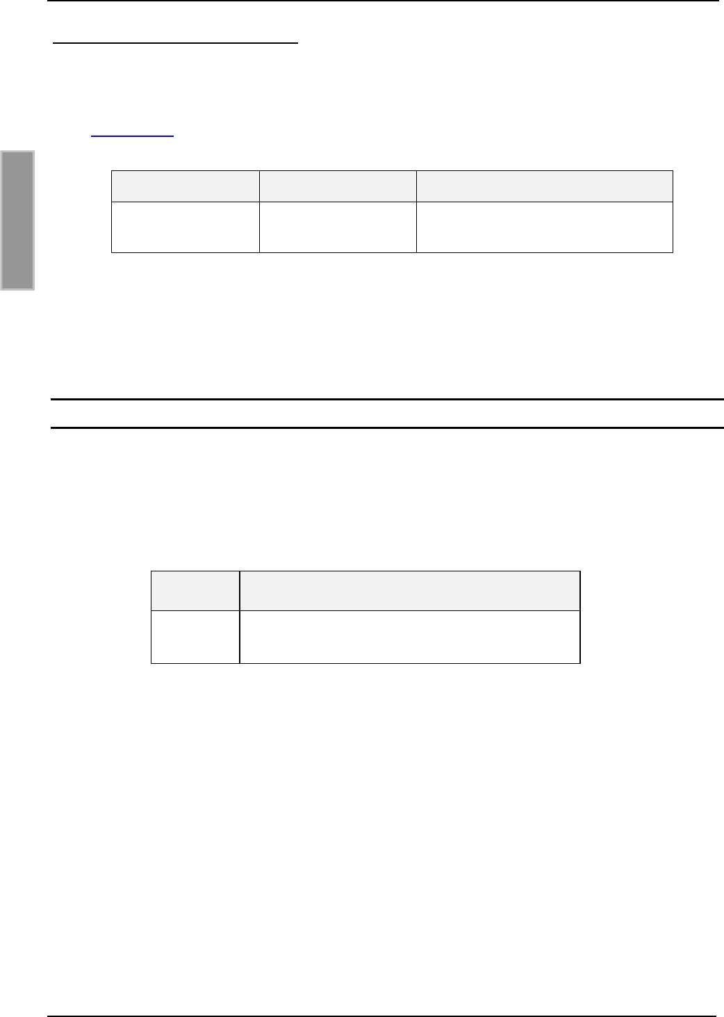
3.4. Antenna terminal X4 (only ID ISC.MR101)
An SMA socket is provided on the circuit board for connecting the external antenna.
The maximum tightening torque for the SMA socket is 0.45 Nm.
(Caution: Higher tightening torque will damage the connector.)
Socket Description
X4 Connecting the external antenna
(input impedance 50Ω)
Table 6: Connecting the external antenna
Note:
•The input impedance for the antenna should be calibrated to a value of 50 Ω±(3 Ω ∠ 3°).
•The optimum operating Q factor of the antenna should be in a range of QB= 10...20. To
determine the operating Q the antenna must be supplied with a 50 Ohm source such as
a network analyzer or frequency generator.
•When connecting an antenna, ensure that it does not exceed the permissible limits pre-
scribed by the national regulations for radio frequency devices.

OBID i-scanInstallation ID ISC.PR / MR101-USB
FEIG ELECTRONIC GmbH Page 9of 14 M50300-1de-ID-B-neu.doc
ENGLISH
3.5. Starting
The reader must be registered to the operating system by the first use.
To do this you should read the manual “Installation OBID USB-driver“.
3.5.1. ID ISC.MR101
For registering the reader to the operating system, the reader must be connected to the power
supply and the USB-cable. In which order the cables are connected will remain left to the user.
The reader should not be used without connected antenna. Due to the reader uses an external
power supply a “Low Powered Hub”-interface is sufficient. The maximum current through the USB-
Interface amounts to 100mA.
3.5.2. ID ISC.PR101
If the reader is connected with the USB-Interface of the computer by using an USB-cable, he reg-
isters in the operating system automatically. The power requirement of the reader amounts to
more than 100 mA. The USB-Interface must be a High Powered Hub. A High Powered Hub sup-
ports the reader up to 500mA.
Note:
The function of the reader is only guaranteed if it is connected to a High Powered Hub.

OBID i-scanInstallation ID ISC.PR / MR101-USB
FEIG ELECTRONIC GmbH Page 10 of 14 M50300-1de-ID-B-neu.doc
ENGLISH
4. Control and display elements
4.1. LED
The reader’s LED can be configured through software.
Table 7shows the standard configuration of the LED.
Abbreviation "RUN "
Description
LED green -Indicates the reader software is running properly.
-Turns on when the reader is ready.
LED red „LABEL“
-Turns on when a label is detected.
LED orange „INITIALIZING“
-Flashes during reader initialization after power-up.
Table 7: Standard configuration of the LEDs

OBID i-scanInstallation ID ISC.PR / MR101-USB
FEIG ELECTRONIC GmbH Page 11 of 14 M50300-1de-ID-B-neu.doc
ENGLISH
5. Technical data
Mechanical Data
•Housing ABS plastic (enclosed)
•Dimensions (W x H x D) 85 x 145 x 31 mm
•Weight 200 g
•Enclosure rating IP 30
•Color RAL 9018
Electrical Data
•Supply Voltage
– ID ISC.MR101
– ID ISC.PR101
12 – 24 V DC ±15 %
5 V DC (via USB)
•Power consumption ID ISC.MR101: max. 8,0 VA
ID ISC.PR101: max. 2,5 VA
•Operating frequency 13.56 MHz
•Transmitting power ID ISC.MR101: 1,0 W
ID ISC.PR101: 0,5 W
•Antenna connection
(only ID ISC.MR101)
SMA female (50Ω)
•Interfaces USB
Functional properties
•Supported transponders ISO 15693 kompatibel, I•Code 1
(optional I•Code EPC und I•Code UID)
•Address setting for interface Device ID of the reader
•Visual indicators 1 LED ( multicolor – red / green)

OBID i-scanInstallation ID ISC.PR / MR101-USB
FEIG ELECTRONIC GmbH Page 12 of 14 M50300-1de-ID-B-neu.doc
ENGLISH
Ambient conditions
•Temperature range
- Operation
- Storage
-25°C to +60°C
-25°C to +70°C
Applicable Norms
•Radio approval
- Europe
- USA
EN 300 330
FCC 47 CFR Part 15
•EMC EN 301 489
•Safety
– Europe
– Human Exposure
EN 60950
EN 50364
OBID i-scanInstallation ID ISC.PR / MR101-USB
FEIG ELECTRONIC GmbH Page 13 of 14 M50300-1de-ID-B-neu.doc
ENGLISH
6. Approvals
6.2. USA (FCC)
FCC ID PJMMR101-PR101
This device complies with Part 15 of the FCC Rules. Operation is subject to the following two
conditions: (1) this device may not cause harmful interference, and (2) this device must accept
any interference received, including interference that may cause undesired operation.
Warning: Any changes or modifications not expressly approved by the party responsible
for compliance could void the user's authority to operate the equipment.
Installation with FCC Approval:
In countries where FCC approval is required, the ID ISC.MR101 Reader may only be operated
using the antennas listed in Table 8. An SMA socket is provided on the circuit board for connecting
the external antenna.
Article No. Part No.
1663.000.00 ID ISC.ANT340/240
Table 8: Antennas with FCC Approval
FCC NOTICE: To comply with FCC part 15 rules in the United States, the system must be
professionally installed to ensure compliance with the Part 15 certification. It is the respon-
sibility of the operator and professional installer to ensure that only certified systems are
deployed in the United States. The use of the system in any other combination (such as co-
located antennas transmitting the same information) is expressly forbidden.
6.2. Europe (CE)
When used according to regulation, this radio equipment conforms with the basic requirements of
Article 3 and the other relevant provisions of the R&TTE Guideline 1999/E6 dated March 99.
Equipment Classification according to ETSI EN 300 330 and ETSI EN 301 489
OBID i-scanInstallation ID ISC.PR / MR101-USB
FEIG ELECTRONIC GmbH Page 14 of 14 M50300-1de-ID-B-neu.doc
ENGLISH
7. Appendix
7.1. Accessories
The following accessories are available for the reader.
Article No. Part No. Description
1691.000.00 ID ISC.MS.MR/PR-A Wall mounting kit for
ID ISC.MR101. and ID ISC.PR101.
1663.000.00 ID ISC.ANT340/240 External antenna
Dimensions: 340mm x 240mm x 9mm
Enclosure rating.: IP30
1451.000.00 ID ISC.ANT300/300 External antenna
Dimensions: 300mm x 300mm x 30mm
Enclosure rating.: IP65
Table 9: Accessories
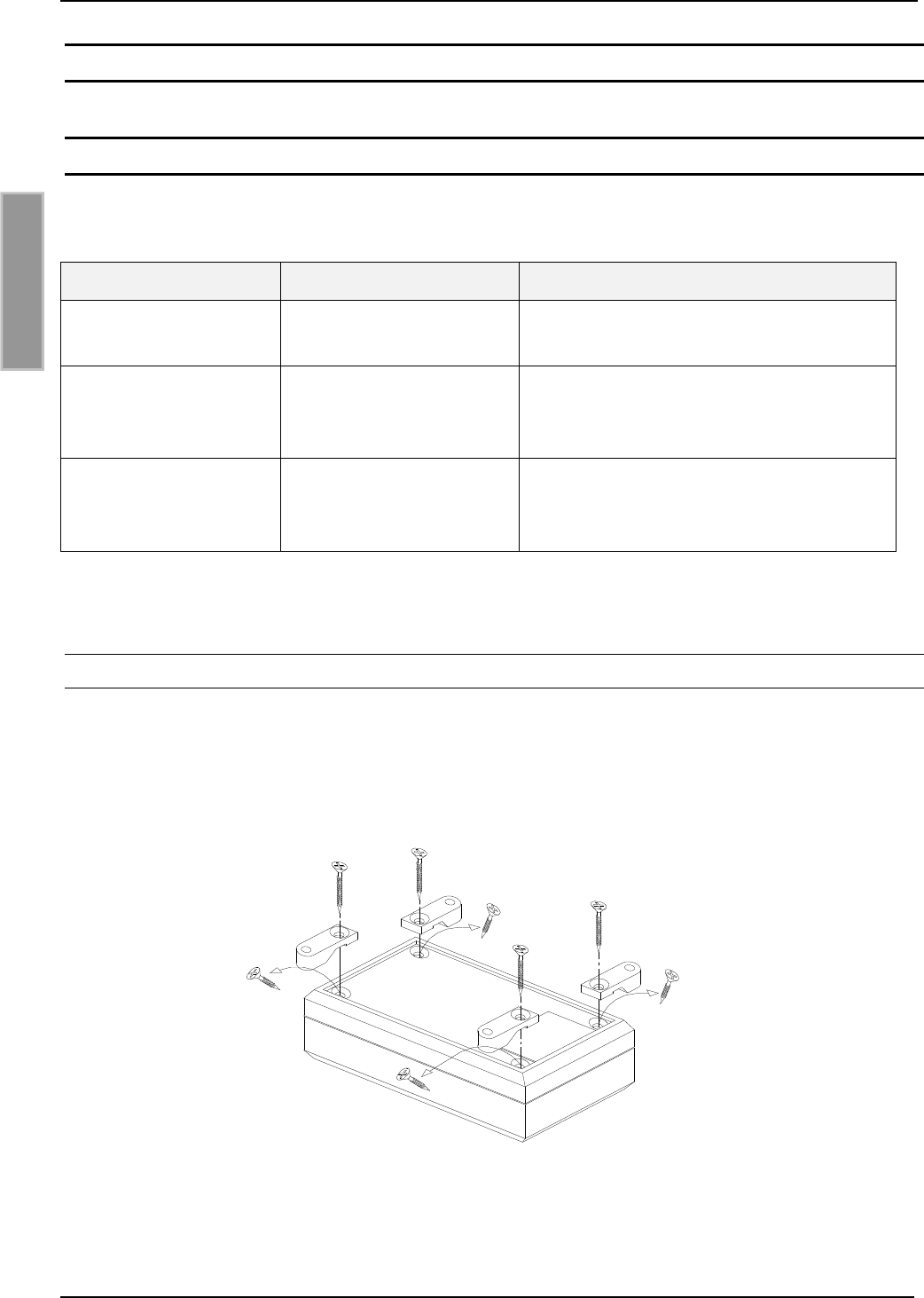
7.1.1. Wall mounting kit ID ISC.MS.MR/PR-A
The wall mounting kit can be used to attach the reader to a flat surface.
•Remove the screws from the back side of the reader
•Attach the individual wall hangers using the screws supplied with the mounting kit
Fig.3 Mounting wall hangers