Feig Electronic MR102 RFID Reader User Manual Annex No
Feig Electronic GmbH RFID Reader Annex No
Contents
- 1. User Maual
- 2. Users Manual
User Maual

State: 2010-03-01
Vers. no.: 1.10
m. dudde hochfrequenz-technik Rottland 5a D-51429 Bergisch Gladbach/ Germany Tel. +49 2207-96890 Fax +49 2207 968920
Annex no. 5
Functional Description /
User Manual
MONTAGE
INSTALLATION
M01211-0de-ID.doc / 2011-07-05
ID ISC.MR102-A/-B
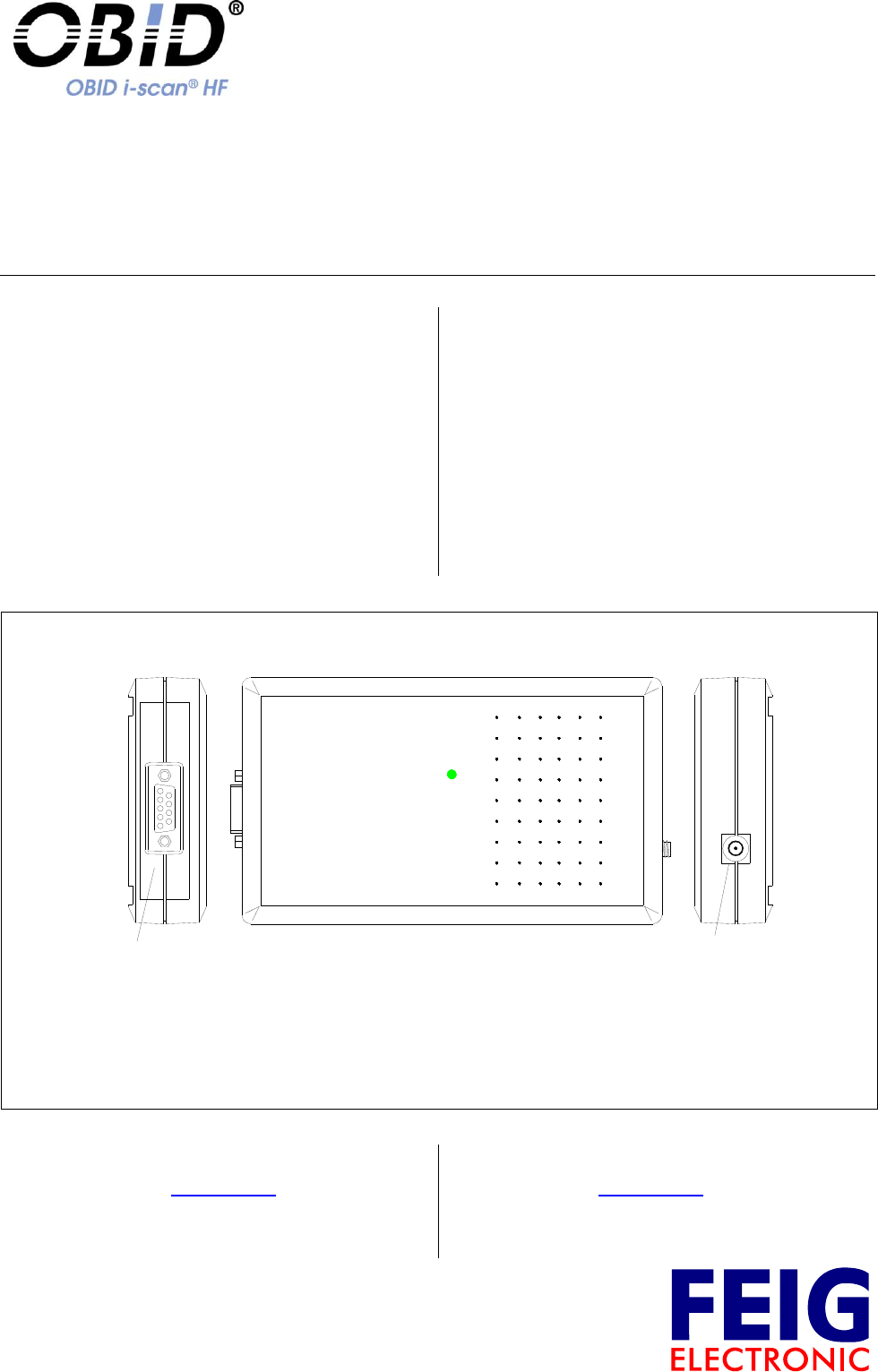
Anschluss und Inbetriebnahme
Installation and starting up
Vielen Dank, dass Sie sich für den Kauf des ID
ISC.MR102 entschieden haben.
Der ID ISC.MR102 ist ein Gerät zum berührungslo-
sen Datenaustausch mit gängigen Transpondern
nach ISO 15693. Dazu benötigt er eine externe An-
tenne. Der Anschluss an einem Computer oder sons-
tiges Gerät erfolgt über die serielle RS232/485
Schnittstelle.
Der Mid Range Reader für unterschiedlichste An-
wendungen in den Bereichen Handel, Logistik und
Industrie geeignet und lässt sich problemlos in be-
stehende Systeme integrieren.
Thank you for deciding to purchase the ID
ISC.MR102
The ID ISC.MR102 is a device for contactless data
exchange with common Transponder according ISO
15693. To this it requires an external Antenna. The
connection to a computer or other equipment is car-
ried out via the serial RS232/485 interface.
The HF Mid Range Reader ID ISC.MR102 is suitable
to be used in fields of applications like library, retail,
logistics and industry and is easy to integrate in exist-
ing systems.
X2 - Serial / VCC
2 - Serial TxD / B-
3 - Serial RxD / A+
5 - Serial GND
7 - VCC GND
9 - VCC 12-24 V DC
ANT 1: Antenna
(50 ± 15 <15°)
RFID by FEIG ELECTRONIC
LED
Weiterführende Informationen, Treiber und Soft-
ware können unter www.feig.de heruntergeladen
werden.
Benutzername: MR102
Passwort: 698reader
Further information’s, driver and software can be
downloaded from www.feig.de.
Username: MR102
Password: 698reader

OBID i-scan®
MONTAGE / INSTALLATION
ID ISC.MR102-A/-B
FEIG ELECTRONIC GmbH
M01211-0de-ID.doc
Sicherheits- und Warnhinweise
Safety Instructions
Das Gerät darf nur für den vom Hersteller
vorgesehenen Zweck verwendet werden.
Die Bedienungsanleitung ist zugriffsfähig
aufzubewahren und jedem Benutzer aus-
zuhändigen.
Unzulässige Veränderungen und die Ver-
wendung von Ersatzteilen und Zusatzein-
richtungen, die nicht vom Hersteller des
Gerätes verkauft oder empfohlen werden,
können Brände, elektrische Schläge und
Verletzungen verursachen. Solche Maß-
nahmen führen daher zu einem Ausschluss
der Haftung und der Hersteller übernimmt
keine Gewährleistung.
Für das Gerät gelten die Gewährleistungs-
bestimmungen des Herstellers in der zum
Zeitpunkt des Kaufs gültigen Fassung. Für
eine ungeeignete, falsche manuelle oder
automatische Einstellung von Parametern für
ein Gerät bzw. ungeeignete Verwendung
eines Gerätes wird keine Haftung
übernommen.
Reparaturen dürfen nur vom Hersteller durch-
geführt werden.
Anschluss-, Inbetriebnahme-, Wartungs-, und
sonstige Arbeiten am Gerät dürfen nur von
Fachkräften mit einschlägiger Ausbildung
erfolgen.
Alle Arbeiten am Gerät und dessen
Aufstellung müssen in Übereinstimmung mit
den nationalen elektrischen Bestimmungen
und den örtlichen Vorschriften durchgeführt
werden.
Bei Arbeiten an dem Gerät müssen die
jeweils gültigen Sicherheitsvorschriften
beachtet werden.
Besonderer Hinweis für
Träger von Herzschrittmachern:
Obwohl dieses Gerät die zulässigen Grenz-
werte für elektromagnetische Felder nicht
überschreitet, sollten Sie einen Mindestab-
stand von 25 cm zwischen dem Gerät und
Ihrem Herzschrittmacher einhalten und sich
nicht für längere Zeit in unmittelbarer Nähe
des Geräts bzw. der Antenne aufhalten.
The device may only be used for the intended
purpose designed by for the manufacturer.
The operation manual should be conveniently
kept available at all times for each user.
Unauthorized changes and the use of spare
parts and additional devices which have not
been sold or recommended by the
manufacturer may cause fire, electric shocks
or injuries. Such unauthorized measures
shall exclude any liability by the
manufacturer.
The liability-prescriptions of the manufacturer
in the issue valid at the time of purchase are
valid for the device. The manufacturer shall
not be held legally responsible for
inaccuracies, errors, or omissions in the
manual or automatically set parameters for a
device or for an incorrect application of a
device.
Repairs may only be executed by the
manufacturer.
Installation, operation, and maintenance
procedures should only be carried out by
qualified personnel.
Use of the device and its installation must be
in accordance with national legal
requirements and local electrical codes .
When working on devices the valid safety
regulations must be observed.
Special advice for
carriers of cardiac pacemakers:
Although this device doesn't exceed the valid
limits for electromagnetic fields you should
keep a minimum distance of 25 cm between
the device and your cardiac pacemaker and
not stay in an immediate proximity of the de-
vice respective the antenna for some time.
OBID i-scan®
MONTAGE / INSTALLATION
ID ISC.MR102-A/-B
FEIG ELECTRONIC GmbH
M01211-0de-ID.doc
Technische Daten
Technical Data
Gehäuse / housing
ABS plastic
Gewicht / weight
200 g / 0,44 lbs
Schutzart / protection class
IP 30
Spannungsversorgung / supply voltage
12 – 24 V DC/
Leistungsaufnahme / power consumption
max. 6 W
Schnittstelle / Interface
-A: RS232, -B: RS485
Temperaturbereich / temperature range
Betrieb / operation
Lagerung / storage
-25°C to +55°C / -13°F to +131°F
-25°C to +85°C / -13°F to +185°F
relative Luftfeuchte / relative air humidity
5-95 % (non-condensing)
Antenne / antenna
External (50 ± 15 < 15°)
Betriebsfrequenz / operating frequency
13,56 MHz
RF-Sendeleistung / RF- transmitting power
1,2 W 1 dB
!
Wichtiger Hinweis:
Nichtbeachtung der nachfolgenden Hinwei-
se kann irreparable Schäden am Gerät zur
Folge haben.
Der Gerät darf nur mit einer
angeschlossenen und abgestimmten
50 Ω ± 15 Ω <15° Antenne betrieben
werden!
Beachten Sie, dass Metallteile in der
Nähe der Antenne zu einer Verstimmung
der Antenne führen!
Bei der Pad-Antenne ID ISC.ANT340240
ist ein Mindestabstand von 20cm zu
Metallteilen einzuhalten!
!
Important Note:
If you do not follow these instructions the
device hardware can be damaged irrepara-
ble.
Use this device only with a connected
and tuned 50 Ω ± 15 Ω <15° antenna!
Note that any metal parts around the
antenna can detune the antenna!
If the Pad-Antenna ID ISC.ANT340240 is
used, keep a minimum distance of 20cm
( 8 inch ) to any metal parts!
Weitere Instruktionen müssen der detail-
lierten Montageanleitung M01210-xd-
ID.pdf entnommen werden.
More instructions must be read in the de-
tailed mounting instruction M01210-xe-
ID.pdf.
Die Funkanlage entspricht, bei bestimmungsgemä-
ßer Verwendung den grundlegenden Anforderungen
des Artikels 3 und den übrigen einschlägigen Be-
stimmungen der R&TTE Richtlinie 1999/5/EG vom
März 99.
Equipment Classification gemäß
ETSI EN 300 330 und ETSI EN 301 489: Class 2
When properly used this radio equipment conforms
to the essential requirements of Article 3 and the
other relevant provisions of the R&TTE Directive
1999/5/EC of March 99.
Equipment Classification according to
ETSI EN 300 330 and ETSI EN 301 489: Class 2

OBID i-scan®
MONTAGE / INSTALLATION
ID ISC.MR102-A/-B
FEIG ELECTRONIC GmbH
M01211-0de-ID.doc
Notice for USA and Canada
FCC ID: PJMMR102, IC: 6633A-MR102
This device complies with Part 15 of the FCC Rules and with RSS-210 of Industry Canada.
Operation is subject to the following two conditions:
(1) this device may not cause harmful interference, and
(2) this device must accept any interference received,
including interference that may cause undesired operation.
Unauthorized modifications may void the authority granted under Federal communications Commission
Rules permitting the operation of this device.
This equipment has been tested and found to comply with the limits for a Class A digital device, pursuant
to Part 15 of the FCC Rules. These limits are designed to provide reasonable protection against harmful
interference when the equipment is operated in a commercial environment. This equipment generates,
uses, and can radiate radio frequency energy and, if not installed and used in accordance with the
instruction manual, may cause harmful interference to radio communications. Operation of this equipment
in a residential area is likely to cause harmful interference in which case the user will be required to
correct the interference at his own expense.
Le présent appareil est conforme aux CNR d'Industrie Canada applicables aux appareils radio exempts
de licence. L'exploitation est autorisée aux deux conditions suivantes :
(1) l'appareil ne doit pas produire de brouillage, et
(2) l'utilisateur de l'appareil doit accepter tout brouillage radioélectrique subi, même si le brouillage est
susceptible d'en compromettre le fonctionnement.
Warning: Any changes or modifications not expressly approved by the party responsible for compliance
could void the user's authority to operate the equipment.
Installation with FCC / IC Approval:
FCC-/IC-NOTICE: To comply with FCC Part 15 Rules in the United States / with IC Radio Standards in Can-
ada, the system must be professionally installed to ensure compliance with the Part 15 certification / IC certi-
fication. It is the responsibility of the operator and professional installer to ensure that only certified systems
are deployed in the United States / Canada. The use of the system in any other combination (such as collo-
cated antennas transmitting the same information) is expressly forbidden. This device has been designed to
operate with the antennas listed below. Antennas not included in this list are strictly prohibited for use with
this device. An SMA socket is provided on the circuit board for connecting the external antenna.
Article No.
Part No.
1663.000.00
ID ISC.ANT340/240-A
2396.000.00
ID ISC.ANT340/240-B
2717.000.00
ID ISC.ANTH200/200-A
3249.000.00
ID ISC.ANT310/310-A
3512.000.00
ID ISC.ANTS370/270-A
1968.000.00
ID ISC.ANT100/100-A
1967.000.00
ID ISC.ANT40/30-A
Table 1: Antennas with FCC / IC Approval
Copyright 2011 by FEIG ELECTRONIC GmbH Lange Straße 4 D-35781 Weilburg
Liefermöglichkeiten und technische Änderungen
vorbehalten.
FEIG ELECTRONIC GmbH übernimmt keine Gewährleis-
tung dafür, dass die in diesem Dokument enthaltenden In-
formationen frei von fremden Schutzrechten sind. FEIG
ELECTRONIC GmbH erteilt mit diesem Dokument keine
Lizenzen auf eigene oder fremde Patente oder andere
Schutzrechte.
Data and design subject to change without notice. Supply
subject to availability.
FEIG ELECTRONIC GmbH assumes no responsibility for
the use of any information contained in this manual and
makes no representation that they free of patent infringe-
ment. FEIG ELECTRONIC GmbH does not convey any li-
cense under its patent rights nor the rights of others.
OBID® and OBID i-scan® are registered trademarks of FEIG ELECTRONIC GmbH.
All cited brand names, product names, or trademarks belong to their respective holders.

MONTAGE
INSTALLATION
M01212-0de-ID.doc / 2011-07-05
ID ISC.MR102-PoE
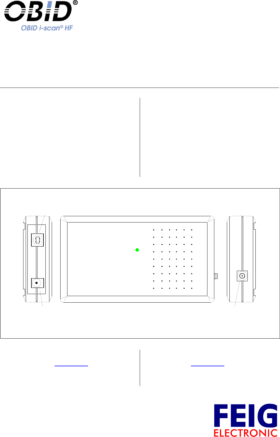
Anschluss und Inbetriebnahme
Installation and starting up
Vielen Dank, dass Sie sich für den Kauf des ID
ISC.MR102 entschieden haben.
Der ID ISC.MR102 ist ein Gerät zum berührungslo-
sen Datenaustausch mit gängigen Transpondern
nach ISO 15693. Dazu benötigt er eine externe An-
tenne. Der Anschluss an einem Computer oder sons-
tiges Gerät erfolgt über die LAN Schnittstelle.
Der Mid Range Reader für unterschiedlichste An-
wendungen in den Bereichen Handel, Logistik und
Industrie geeignet und lässt sich problemlos in be-
stehende Systeme integrieren.
Thank you for deciding to purchase the ID
ISC.MR102
The ID ISC.MR102 is a device for contactless data
exchange with common Transponder according ISO
15693. To this it requires an external Antenna. The
connection to a computer or other equipment is car-
ried out via the LAN interface
The HF Mid Range Reader ID ISC.MR102 is suitable
to be used in fields of applications like library, retail,
logistics and industry and is easy to integrate in exist-
ing systems.
X4 - LAN / PoE
X1: VCC
(12 - 24 VDC) ANT 1: Antenna
(50 ± 15 <15°)
RFID by FEIG ELECTRONIC
LED
Weiterführende Informationen, Treiber und Soft-
ware können unter www.feig.de heruntergeladen
werden.
Benutzername: MR102
Passwort: 698reader
Further information’s, driver and software can be
downloaded from www.feig.de.
Username: MR102
Password: 698reader
IP-Adresse 192.168.10.10
Subnet-Mask 255.255.255.0
Port 10001
DHCP AUS

OBID i-scan®
MONTAGE / INSTALLATION
ID ISC.MR102-PoE
FEIG ELECTRONIC GmbH
M01212-0de-ID.doc
Sicherheits- und Warnhinweise
Safety Instructions
Das Gerät darf nur für den vom Hersteller
vorgesehenen Zweck verwendet werden.
Die Bedienungsanleitung ist zugriffsfähig
aufzubewahren und jedem Benutzer aus-
zuhändigen.
Unzulässige Veränderungen und die Ver-
wendung von Ersatzteilen und Zusatzein-
richtungen, die nicht vom Hersteller des
Gerätes verkauft oder empfohlen werden,
können Brände, elektrische Schläge und
Verletzungen verursachen. Solche Maß-
nahmen führen daher zu einem Ausschluss
der Haftung und der Hersteller übernimmt
keine Gewährleistung.
Für das Gerät gelten die Gewährleistungs-
bestimmungen des Herstellers in der zum
Zeitpunkt des Kaufs gültigen Fassung. Für
eine ungeeignete, falsche manuelle oder
automatische Einstellung von Parametern für
ein Gerät bzw. ungeeignete Verwendung
eines Gerätes wird keine Haftung
übernommen.
Reparaturen dürfen nur vom Hersteller durch-
geführt werden.
Anschluss-, Inbetriebnahme-, Wartungs-, und
sonstige Arbeiten am Gerät dürfen nur von
Fachkräften mit einschlägiger Ausbildung
erfolgen.
Alle Arbeiten am Gerät und dessen
Aufstellung müssen in Übereinstimmung mit
den nationalen elektrischen Bestimmungen
und den örtlichen Vorschriften durchgeführt
werden.
Bei Arbeiten an dem Gerät müssen die
jeweils gültigen Sicherheitsvorschriften
beachtet werden.
Besonderer Hinweis für
Träger von Herzschrittmachern:
Obwohl dieses Gerät die zulässigen Grenz-
werte für elektromagnetische Felder nicht
überschreitet, sollten Sie einen Mindestab-
stand von 25 cm zwischen dem Gerät und
Ihrem Herzschrittmacher einhalten und sich
nicht für längere Zeit in unmittelbarer Nähe
des Geräts bzw. der Antenne aufhalten.
The device may only be used for the intended
purpose designed by for the manufacturer.
The operation manual should be conveniently
kept available at all times for each user.
Unauthorized changes and the use of spare
parts and additional devices which have not
been sold or recommended by the
manufacturer may cause fire, electric shocks
or injuries. Such unauthorized measures
shall exclude any liability by the
manufacturer.
The liability-prescriptions of the manufacturer
in the issue valid at the time of purchase are
valid for the device. The manufacturer shall
not be held legally responsible for
inaccuracies, errors, or omissions in the
manual or automatically set parameters for a
device or for an incorrect application of a
device.
Repairs may only be executed by the
manufacturer.
Installation, operation, and maintenance
procedures should only be carried out by
qualified personnel.
Use of the device and its installation must be
in accordance with national legal
requirements and local electrical codes .
When working on devices the valid safety
regulations must be observed.
Special advice for
carriers of cardiac pacemakers:
Although this device doesn't exceed the valid
limits for electromagnetic fields you should
keep a minimum distance of 25 cm between
the device and your cardiac pacemaker and
not stay in an immediate proximity of the de-
vice respective the antenna for some time.

OBID i-scan®
MONTAGE / INSTALLATION
ID ISC.MR102-PoE
FEIG ELECTRONIC GmbH
M01212-0de-ID.doc
Technische Daten
Technical Data
Gehäuse / housing
ABS plastic
Gewicht / weight
200 g / 0,44 lbs
Schutzart / protection class
IP 30
Spannungsversorgung / supply voltage
X1: 12 – 24 V DC/ or
X4: PoE (IEEE802.3af, Class2)
Leistungsaufnahme / power consumption
max. 6 W
Temperaturbereich / temperature range
Betrieb / operation
Lagerung / storage
-25°C to +55°C / -13°F to +131°F
-25°C to +85°C / -13°F to +185°F
relative Luftfeuchte / relative air humidity
95 % (non-condensing)
Antenne / antenna
External (50 ± 15 < 15°)
Betriebsfrequenz / operating frequency
13,56 MHz
RF-Sendeleistung / RF- transmitting power
1,2 W 1 dB
!
Wichtiger Hinweis:
Nichtbeachtung der nachfolgenden Hinwei-
se kann irreparable Schäden am Gerät zur
Folge haben.
Der Gerät darf nur mit einer
angeschlossenen und abgestimmten
50 Ω ± 15 Ω <15° Antenne betrieben
werden!
Beachten Sie, dass Metallteile in der
Nähe der Antenne zu einer Verstimmung
der Antenne führen!
Bei der Pad-Antenne ID ISC.ANT340240
ist ein Mindestabstand von 20cm zu
Metallteilen einzuhalten!
!
Important Note:
If you do not follow these instructions the
device hardware can be damaged irrepara-
ble.
Use this device only with a connected
and tuned 50 Ω ± 15 Ω <15° antenna!
Note that any metal parts around the
antenna can detune the antenna!
If the Pad-Antenna ID ISC.ANT340240 is
used, keep a minimum distance of 20cm
( 8 inch ) to any metal parts!
Weitere Instruktionen müssen der detail-
lierten Montageanleitung M01210-xd-
ID.pdf entnommen werden.
More instructions must be read in the de-
tailed mounting instruction M01210-xe-
ID.pdf.
Die Funkanlage entspricht, bei bestimmungsgemä-
ßer Verwendung den grundlegenden Anforderungen
des Artikels 3 und den übrigen einschlägigen Be-
stimmungen der R&TTE Richtlinie 1999/5/EG vom
März 99.
Equipment Classification gemäß
ETSI EN 300 330 und ETSI EN 301 489: Class 2
When properly used this radio equipment conforms
to the essential requirements of Article 3 and the
other relevant provisions of the R&TTE Directive
1999/5/EC of March 99.
Equipment Classification according to
ETSI EN 300 330 and ETSI EN 301 489: Class 2

OBID i-scan®
MONTAGE / INSTALLATION
ID ISC.MR102-PoE
FEIG ELECTRONIC GmbH
M01212-0de-ID.doc
Notice for USA and Canada
FCC ID: PJMMR102, IC: 6633A-MR102
This device complies with Part 15 of the FCC Rules and with RSS-210 of Industry Canada.
Operation is subject to the following two conditions:
(1) this device may not cause harmful interference, and
(2) this device must accept any interference received,
including interference that may cause undesired operation.
Unauthorized modifications may void the authority granted under Federal communications Commission
Rules permitting the operation of this device.
This equipment has been tested and found to comply with the limits for a Class A digital device, pursuant
to Part 15 of the FCC Rules. These limits are designed to provide reasonable protection against harmful
interference when the equipment is operated in a commercial environment. This equipment generates,
uses, and can radiate radio frequency energy and, if not installed and used in accordance with the
instruction manual, may cause harmful interference to radio communications. Operation of this equipment
in a residential area is likely to cause harmful interference in which case the user will be required to
correct the interference at his own expense.
Le présent appareil est conforme aux CNR d'Industrie Canada applicables aux appareils radio exempts
de licence. L'exploitation est autorisée aux deux conditions suivantes :
(1) l'appareil ne doit pas produire de brouillage, et
(2) l'utilisateur de l'appareil doit accepter tout brouillage radioélectrique subi, même si le brouillage est
susceptible d'en compromettre le fonctionnement.
Warning: Any changes or modifications not expressly approved by the party responsible for compliance
could void the user's authority to operate the equipment.
Installation with FCC / IC Approval:
FCC-/IC-NOTICE: To comply with FCC Part 15 Rules in the United States / with IC Radio Standards in Can-
ada, the system must be professionally installed to ensure compliance with the Part 15 certification / IC certi-
fication. It is the responsibility of the operator and professional installer to ensure that only certified systems
are deployed in the United States / Canada. The use of the system in any other combination (such as collo-
cated antennas transmitting the same information) is expressly forbidden. This device has been designed to
operate with the antennas listed below. Antennas not included in this list are strictly prohibited for use with
this device. An SMA socket is provided on the circuit board for connecting the external antenna.
Article No.
Part No.
1663.000.00
ID ISC.ANT340/240-A
2396.000.00
ID ISC.ANT340/240-B
2717.000.00
ID ISC.ANTH200/200-A
3249.000.00
ID ISC.ANT310/310-A
3512.000.00
ID ISC.ANTS370/270-A
1968.000.00
ID ISC.ANT100/100-A
1967.000.00
ID ISC.ANT40/30-A
Table 1: Antennas with FCC / IC Approval
Copyright 2011 by FEIG ELECTRONIC GmbH Lange Straße 4 D-35781 Weilburg
Liefermöglichkeiten und technische Änderungen
vorbehalten.
FEIG ELECTRONIC GmbH übernimmt keine Gewährleis-
tung dafür, dass die in diesem Dokument enthaltenden In-
formationen frei von fremden Schutzrechten sind. FEIG
ELECTRONIC GmbH erteilt mit diesem Dokument keine
Lizenzen auf eigene oder fremde Patente oder andere
Schutzrechte.
Data and design subject to change without notice. Supply
subject to availability.
FEIG ELECTRONIC GmbH assumes no responsibility for
the use of any information contained in this manual and
makes no representation that they free of patent infringe-
ment. FEIG ELECTRONIC GmbH does not convey any li-
cense under its patent rights nor the rights of others.
OBID® and OBID i-scan® are registered trademarks of FEIG ELECTRONIC GmbH.
All cited brand names, product names, or trademarks belong to their respective holders.
MONTAGE
INSTALLATION
M01213-0de-ID.doc / 2011-07-05
ID ISC.MR102-USB
Anschluss und Inbetriebnahme
Installation and starting up
Vielen Dank, dass Sie sich für den Kauf des ID
ISC.MR102 entschieden haben.
Der ID ISC.MR102 ist ein Gerät zum berührungslo-
sen Datenaustausch mit gängigen Transpondern
nach ISO 15693. Dazu benötigt er eine externe An-
tenne. Der Anschluss an einem Computer oder sons-
tiges Gerät erfolgt über die USB Schnittstelle.
Der Mid Range Reader für unterschiedlichste An-
wendungen in den Bereichen Handel, Logistik und
Industrie geeignet und lässt sich problemlos in be-
stehende Systeme integrieren.
Thank you for deciding to purchase the ID
ISC.MR102
The ID ISC.MR102 is a device for contactless data
exchange with common Transponder according ISO
15693. To this it requires an external Antenna. The
connection to a computer or other equipment is car-
ried out via the USB interface.
The HF Mid Range Reader ID ISC.MR102 is suitable
to be used in fields of applications like library, retail,
logistics and industry and is easy to integrate in exist-
ing systems.
X3 - USB
X1 - VCC
12 - 24 VDC
RFID by FEIG ELECTRONIC
LED
ANT 1: Antenna
(50 ± 15 <15°)
Weiterführende Informationen, Treiber und Soft-
ware können unter www.feig.de heruntergeladen
werden.
Benutzername: MR102
Passwort: 698reader
Further information’s, driver and software can be
downloaded from www.feig.de.
Username: MR102
Password: 698reader

OBID i-scan®
MONTAGE / INSTALLATION
ID ISC.MR102-USB
FEIG ELECTRONIC GmbH
M01213-0de-ID.doc
Sicherheits- und Warnhinweise
Safety Instructions
Das Gerät darf nur für den vom Hersteller
vorgesehenen Zweck verwendet werden.
Die Bedienungsanleitung ist zugriffsfähig
aufzubewahren und jedem Benutzer aus-
zuhändigen.
Unzulässige Veränderungen und die Ver-
wendung von Ersatzteilen und Zusatzein-
richtungen, die nicht vom Hersteller des
Gerätes verkauft oder empfohlen werden,
können Brände, elektrische Schläge und
Verletzungen verursachen. Solche Maß-
nahmen führen daher zu einem Ausschluss
der Haftung und der Hersteller übernimmt
keine Gewährleistung.
Für das Gerät gelten die Gewährleistungs-
bestimmungen des Herstellers in der zum
Zeitpunkt des Kaufs gültigen Fassung. Für
eine ungeeignete, falsche manuelle oder
automatische Einstellung von Parametern für
ein Gerät bzw. ungeeignete Verwendung
eines Gerätes wird keine Haftung
übernommen.
Reparaturen dürfen nur vom Hersteller durch-
geführt werden.
Anschluss-, Inbetriebnahme-, Wartungs-, und
sonstige Arbeiten am Gerät dürfen nur von
Fachkräften mit einschlägiger Ausbildung
erfolgen.
Alle Arbeiten am Gerät und dessen
Aufstellung müssen in Übereinstimmung mit
den nationalen elektrischen Bestimmungen
und den örtlichen Vorschriften durchgeführt
werden.
Bei Arbeiten an dem Gerät müssen die
jeweils gültigen Sicherheitsvorschriften
beachtet werden.
Besonderer Hinweis für
Träger von Herzschrittmachern:
Obwohl dieses Gerät die zulässigen Grenz-
werte für elektromagnetische Felder nicht
überschreitet, sollten Sie einen Mindestab-
stand von 25 cm zwischen dem Gerät und
Ihrem Herzschrittmacher einhalten und sich
nicht für längere Zeit in unmittelbarer Nähe
des Geräts bzw. der Antenne aufhalten.
The device may only be used for the intended
purpose designed by for the manufacturer.
The operation manual should be conveniently
kept available at all times for each user.
Unauthorized changes and the use of spare
parts and additional devices which have not
been sold or recommended by the
manufacturer may cause fire, electric shocks
or injuries. Such unauthorized measures
shall exclude any liability by the
manufacturer.
The liability-prescriptions of the manufacturer
in the issue valid at the time of purchase are
valid for the device. The manufacturer shall
not be held legally responsible for
inaccuracies, errors, or omissions in the
manual or automatically set parameters for a
device or for an incorrect application of a
device.
Repairs may only be executed by the
manufacturer.
Installation, operation, and maintenance
procedures should only be carried out by
qualified personnel.
Use of the device and its installation must be
in accordance with national legal
requirements and local electrical codes .
When working on devices the valid safety
regulations must be observed.
Special advice for
carriers of cardiac pacemakers:
Although this device doesn't exceed the valid
limits for electromagnetic fields you should
keep a minimum distance of 25 cm between
the device and your cardiac pacemaker and
not stay in an immediate proximity of the de-
vice respective the antenna for some time.
OBID i-scan®
MONTAGE / INSTALLATION
ID ISC.MR102-USB
FEIG ELECTRONIC GmbH
M01213-0de-ID.doc
Technische Daten
Technical Data
Gehäuse / housing
ABS plastic
Gewicht / weight
200 g / 0,44 lbs
Schutzart / protection class
IP 30
Spannungsversorgung / supply voltage
12 – 24 V DC/
Leistungsaufnahme / power consumption
max. 6 W
Temperaturbereich / temperature range
Betrieb / operation
Lagerung / storage
-25°C to +55°C / -13°F to +131°F
-25°C to +85°C / -13°F to +185°F
relative Luftfeuchte / relative air humidity
5-95 % (non-condensing)
Antenne / antenna
External (50 ± 15 < 15°)
Betriebsfrequenz / operating frequency
13,56 MHz
RF-Sendeleistung / RF- transmitting power
1,2 W 1 dB
!
Wichtiger Hinweis:
Nichtbeachtung der nachfolgenden Hinwei-
se kann irreparable Schäden am Gerät zur
Folge haben.
Der Gerät darf nur mit einer
angeschlossenen und abgestimmten
50 Ω ± 15 Ω <15° Antenne betrieben
werden!
Beachten Sie, dass Metallteile in der
Nähe der Antenne zu einer Verstimmung
der Antenne führen!
Bei der Pad-Antenne ID ISC.ANT340240
ist ein Mindestabstand von 20cm zu
Metallteilen einzuhalten!
!
Important Note:
If you do not follow these instructions the
device hardware can be damaged irrepara-
ble.
Use this device only with a connected
and tuned 50 Ω ± 15 Ω <15° antenna!
Note that any metal parts around the
antenna can detune the antenna!
If the Pad-Antenna ID ISC.ANT340240 is
used, keep a minimum distance of 20cm
( 8 inch ) to any metal parts!
Weitere Instruktionen müssen der detail-
lierten Montageanleitung M01210-xd-
ID.pdf entnommen werden.
More instructions must be read in the de-
tailed mounting instruction M01210-xe-
ID.pdf.
Die Funkanlage entspricht, bei bestimmungsgemä-
ßer Verwendung den grundlegenden Anforderungen
des Artikels 3 und den übrigen einschlägigen Be-
stimmungen der R&TTE Richtlinie 1999/5/EG vom
März 99.
Equipment Classification gemäß
ETSI EN 300 330 und ETSI EN 301 489: Class 2
When properly used this radio equipment conforms
to the essential requirements of Article 3 and the
other relevant provisions of the R&TTE Directive
1999/5/EC of March 99.
Equipment Classification according to
ETSI EN 300 330 and ETSI EN 301 489: Class 2
OBID i-scan®
MONTAGE / INSTALLATION
ID ISC.MR102-USB
FEIG ELECTRONIC GmbH
M01213-0de-ID.doc
Notice for USA and Canada
FCC ID: PJMMR102, IC: 6633A-MR102
This device complies with Part 15 of the FCC Rules and with RSS-210 of Industry Canada.
Operation is subject to the following two conditions:
(1) this device may not cause harmful interference, and
(2) this device must accept any interference received,
including interference that may cause undesired operation.
Unauthorized modifications may void the authority granted under Federal communications Commission
Rules permitting the operation of this device.
This equipment has been tested and found to comply with the limits for a Class A digital device, pursuant
to Part 15 of the FCC Rules. These limits are designed to provide reasonable protection against harmful
interference when the equipment is operated in a commercial environment. This equipment generates,
uses, and can radiate radio frequency energy and, if not installed and used in accordance with the
instruction manual, may cause harmful interference to radio communications. Operation of this equipment
in a residential area is likely to cause harmful interference in which case the user will be required to
correct the interference at his own expense.
Le présent appareil est conforme aux CNR d'Industrie Canada applicables aux appareils radio exempts
de licence. L'exploitation est autorisée aux deux conditions suivantes :
(1) l'appareil ne doit pas produire de brouillage, et
(2) l'utilisateur de l'appareil doit accepter tout brouillage radioélectrique subi, même si le brouillage est
susceptible d'en compromettre le fonctionnement.
Warning: Any changes or modifications not expressly approved by the party responsible for compliance
could void the user's authority to operate the equipment.
Installation with FCC / IC Approval:
FCC-/IC-NOTICE: To comply with FCC Part 15 Rules in the United States / with IC Radio Standards in Can-
ada, the system must be professionally installed to ensure compliance with the Part 15 certification / IC certi-
fication. It is the responsibility of the operator and professional installer to ensure that only certified systems
are deployed in the United States / Canada. The use of the system in any other combination (such as collo-
cated antennas transmitting the same information) is expressly forbidden. This device has been designed to
operate with the antennas listed below. Antennas not included in this list are strictly prohibited for use with
this device. An SMA socket is provided on the circuit board for connecting the external antenna.
Article No.
Part No.
1663.000.00
ID ISC.ANT340/240-A
2396.000.00
ID ISC.ANT340/240-B
2717.000.00
ID ISC.ANTH200/200-A
3249.000.00
ID ISC.ANT310/310-A
3512.000.00
ID ISC.ANTS370/270-A
1968.000.00
ID ISC.ANT100/100-A
1967.000.00
ID ISC.ANT40/30-A
Table 1: Antennas with FCC / IC Approval
Copyright 2011 by FEIG ELECTRONIC GmbH Lange Straße 4 D-35781 Weilburg-Waldhausen
Liefermöglichkeiten und technische Änderungen
vorbehalten.
FEIG ELECTRONIC GmbH übernimmt keine Gewährleis-
tung dafür, dass die in diesem Dokument enthaltenden In-
formationen frei von fremden Schutzrechten sind. FEIG
ELECTRONIC GmbH erteilt mit diesem Dokument keine
Lizenzen auf eigene oder fremde Patente oder andere
Schutzrechte.
Data and design subject to change without notice. Supply
subject to availability.
FEIG ELECTRONIC GmbH assumes no responsibility for
the use of any information contained in this manual and
makes no representation that they free of patent infringe-
ment. FEIG ELECTRONIC GmbH does not convey any li-
cense under its patent rights nor the rights of others.
OBID® and OBID i-scan® are registered trademarks of FEIG ELECTRONIC GmbH.
All cited brand names, product names, or trademarks belong to their respective holders.
MONTAGE
INSTALLATION
draft
public (B)
2011-07-11
M10414-0de-ID-B_110711.doc
ID ISC.SPAD102
Shielded Pad Reader
(deutsch / english)


OBID i-scan®
Montage
ID ISC.SPAD102
FEIG ELECTRONIC GmbH
Seite 3 von 32
M10414-0de-ID-B_110711.doc
D E U T S C H
Hinweis
Copyright 2011 by
FEIG ELECTRONIC GmbH
Lange Straße 4
D-35781 Weilburg
Tel.: +49 6471 3109-0
http://www.feig.de
Alle früheren Ausgaben verlieren mit dieser Ausgabe ihre Gültigkeit.
Die Angaben in diesem Dokument können ohne vorherige Ankündigung geändert werden.
Weitergabe sowie Vervielfältigung dieses Dokuments, Verwertung und Mitteilung ihres Inhalts sind nicht
gestattet, soweit nicht ausdrücklich zugestanden. Zuwiderhandlung verpflichtet zu Schadenersatz. Alle
Rechte für den Fall der Patenterteilung oder Gebrauchsmuster-Eintragung vorbehalten.
Die Zusammenstellung der Informationen in diesem Dokument erfolgt nach bestem Wissen und Gewissen.
FEIG ELECTRONIC GmbH übernimmt keine Gewährleistung für die Richtigkeit und Vollständigkeit der An-
gaben in diesem Dokument. Insbesondere kann FEIG ELECTRONIC GmbH nicht für Folgeschäden auf
Grund fehlerhafter oder unvollständiger Angaben haftbar gemacht werden. Da sich Fehler, trotz aller Bemü-
hungen nie vollständig vermeiden lassen, sind wir für Hinweise jederzeit dankbar.
Die in diesem Dokument gemachten Installationsempfehlungen gehen von günstigsten Rahmenbedingun-
gen aus. FEIG ELECTRONIC GmbH übernimmt keine Gewähr für die einwandfreie Funktion in systemfrem-
den Umgebungen.
FEIG ELECTRONIC GmbH übernimmt keine Gewährleistung dafür, dass die in diesem Dokument enthal-
tenden Informationen frei von fremden Schutzrechten sind. FEIG ELECTRONIC GmbH erteilt mit diesem
Dokument keine Lizenzen auf eigene oder fremde Patente oder andere Schutzrechte.
OBID® und OBID i-scan® ist ein eingetragenes Warenzeichen der FEIG ELECTRONIC GmbH

OBID i-scan®
Montage
ID ISC.SPAD102
FEIG ELECTRONIC GmbH
Seite 4 von 32
M10414-0de-ID-B_110711.doc
D E U T S C H
Inhalt
1 Sicherheits- und Warnhinweise – vor Inbetriebnahme unbedingt lesen 5
2 Leistungsmerkmale 6
2.1 Bestellbezeichnung .................................................................................................... 6
2.2 Lieferumfang ............................................................................................................... 6
3 Abmessungen und Montage 7
3.1 Abmessungen ............................................................................................................. 7
3.2 Montage und Tisch ..................................................................................................... 8
4 Anschlüsse 9
4.1 Versorgungsspannung ............................................................................................... 9
4.1.1 Versorgungsspannung über X1 ................................................................................ 9
4.1.2 Versorgungsspannung über PoE (Power over Ethernet) (ID ISC.SPAD102-PoE) .. 10
4.2 Schnittstellen ............................................................................................................ 11
4.2.1 USB-Schnittstelle (ID ISC.SPAD102-USB) ............................................................. 11
4.2.2 Ethernet-Schnittstelle (ID ISC.SPAD102-PoE) ....................................................... 12
5 Anzeigeelement (LED) 13
6 Technische Daten 14
6.1 Zulassung .................................................................................................................. 16
6.1.1 Europa (CE) ........................................................................................................... 16
6.1.2 USA und Kanada ................................................................................................... 17

OBID i-scan®
Montage
ID ISC.SPAD102
FEIG ELECTRONIC GmbH
Seite 5 von 32
M10414-0de-ID-B_110711.doc
D E U T S C H
1 Sicherheits- und Warnhinweise – vor Inbetriebnahme unbedingt lesen
Das Gerät darf nur für den vom Hersteller vorgesehenen Zweck verwendet werden..
Die Bedienungsanleitung ist zugriffsfähig aufzubewahren und jedem Benutzer auszuhändigen.
Unzulässige Veränderungen und die Verwendung von Ersatzteilen und Zusatzeinrichtungen,
die nicht vom Hersteller des Gerätes verkauft oder empfohlen werden, können Brände,
elektrische Schläge und Verletzungen verursachen. Solche Maßnahmen führen daher zu
einem Ausschluss der Haftung und der Hersteller übernimmt keine Gewährleistung.
Für das Gerät gelten die Gewährleistungsbestimmungen des Herstellers in der zum Zeitpunkt
des Kaufs gültigen Fassung. Für eine ungeeignete, falsche manuelle oder automatische
Einstellung von Parametern für ein Gerät bzw. ungeeignete Verwendung eines Gerätes wird
keine Haftung übernommen.
Reparaturen dürfen nur vom Hersteller durchgeführt werden.
Anschluss-, Inbetriebnahme-, Wartungs-, und sonstige Arbeiten am Gerät dürfen nur von
Elektrofachkräften mit einschlägiger Ausbildung erfolgen.
Alle Arbeiten am Gerät und dessen Aufstellung müssen in Übereinstimmung mit den
nationalen elektrischen Bestimmungen und den örtlichen Vorschriften durchgeführt werden.
Beim Arbeiten an dem Gerät müssen die jeweils gültigen Sicherheitsvorschriften beachtet
werden.
Besonderer Hinweis für Träger von Herzschrittmachern:
Obwohl dieses Gerät die zulässigen Grenzwerte für elektromagnetische Felder nicht
überschreitet, sollten Sie einen Mindestabstand von 25 cm zwischen dem Gerät und Ihrem
Herzschrittmacher einhalten und sich nicht für längere Zeit in unmittelbarer Nähe des
Geräts bzw. der Antenne aufhalten.

OBID i-scan®
Montage
ID ISC.SPAD102
FEIG ELECTRONIC GmbH
Seite 6 von 32
M10414-0de-ID-B_110711.doc
D E U T S C H
2 Leistungsmerkmale
Der Shielded Pad Reader ID ISC.SPAD102 ist ein Gerät zum berührungslosen Datenaustausch
mit gängigen Transpondern mit Betriebsfrequenz 13,56 MHz und einer maximalen Ausgangsleis-
tung von 1,5 W. Der Shielded Pad Reader eignet sich für alle Anwendungen, bei denen mittlere
Lesereichweiten benötigt werden. Eine geschirmte Antenne ist zusammen mit dem Reader in ei-
nem Kunststoffgehäuse integriert.
Durch die Schirmung der Antenne wird die Kommunikation mit Transpondern weitgehend auf den
Bereich über der Antenne beschränkt.
Die Möglichkeit die Antenne ID ISC.SPAD102 direkt auf Metall zu platzieren, ohne das die Anten-
neneigenschaft negativ beeinflusst wird, ist ein weiterer wesentlicher Vorteil dieser Antenne.
Eine Anticollision-Funktion ermöglicht das gleichzeitige Lesen von bis zu 30 Transpondern.
Die Antenne kann sowohl für Güter- als auch für Personenerkennung verwendet werden. Die Vor-
zugsrichtung eines Smart Label ist parallel zu Antennenfläche.
2.1 Bestellbezeichnung
Folgende Shielded Pad Reader sind verfügbar:
Table 2-1: Bestellbezeichnung Shielded Pad-Reader
Artikel Nr.
Readertyp
Beschreibung
3756.000.00
ID ISC.SPAD102-USB
Shielded Pad Reader mit USB Schnittstelle
3513.000.00
ID ISC.SPAD102-PoE
Shielded Pad Reader mit Ethernet Schnittstelle (PoE)
2.2 Lieferumfang
Im Lieferumfang ist ein Stück Shielded Pad Reader ID ISC.PAD102 mit Anschlusskabel und Kurz-
anleitung enthalten.
OBID i-scan®
Montage
ID ISC.SPAD102
FEIG ELECTRONIC GmbH
Seite 7 von 32
M10414-0de-ID-B_110711.doc
D E U T S C H
3 Abmessungen und Montage
Der Reader ist für den Betrieb auf einer ebenen Oberfläche (z.B. Tisch) oder zur Montage hinter
oder unter einer Montageplatte (nicht metallisch) im Innenbereich konzipiert.
Für den Betrieb auf einer ebenen Oberfläche befinden sich Gummifüße auf der Unterseite der An-
tenne.
Die Montage hinter oder unter einer Montageplatte erfolgt über Döme, die durch Bohrungen im
Gehäuseunterteil angedeutet sind.
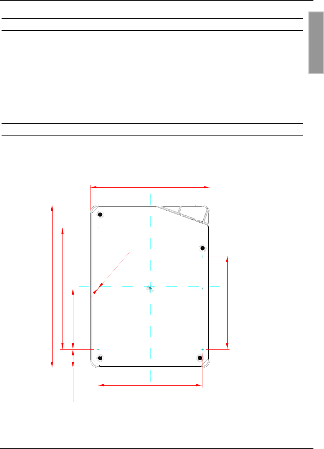
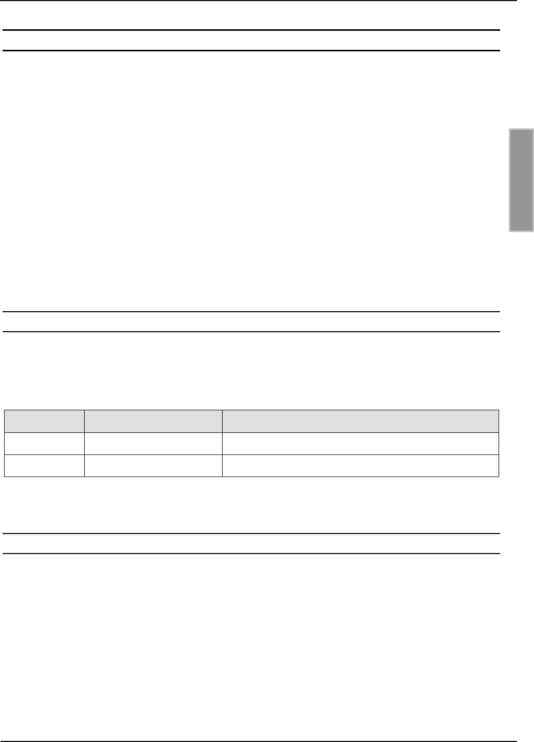
3.1 Abmessungen
Die Außenmaße und die Position der Befestigungsdurchbrüche des Shielded Pad-Readers sind in
folgender Abbildung dargestellt:
Alle Maße in mm (inch):
376,2 (14,81)
275,7 (10,85)
280 (11,02)
215 (8,46)
140 ( 5,51)42,8 (1,68)
240 (9,44)
6 x Ø 1,5 (0,06)
Abbildung 1: Außenmaße und Position Befestigungsdurchbrüche (Unterseite)

OBID i-scan®
Montage
ID ISC.SPAD102
FEIG ELECTRONIC GmbH
Seite 8 von 32
M10414-0de-ID-B_110711.doc
D E U T S C H
3.2 Montage und Tisch
Für die Montage des Shielded Pad-Readers unter einer Tisch- oder Montageplatte sind zunächst
die Durchbrüche herzustellen. Die Position für die Durchbrüche sind im Gehäuseunterteil durch
1,5 mm Bohrungen angedeutet (siehe Abbildung 1). Bohrungen an anderen Stellen können zur
Zerstörung der Antenne führen.
OBID i-scan®
Montage
ID ISC.SPAD102
FEIG ELECTRONIC GmbH
Seite 9 von 32
M10414-0de-ID-B_110711.doc
D E U T S C H
4 Anschlüsse
4.1 Versorgungsspannung
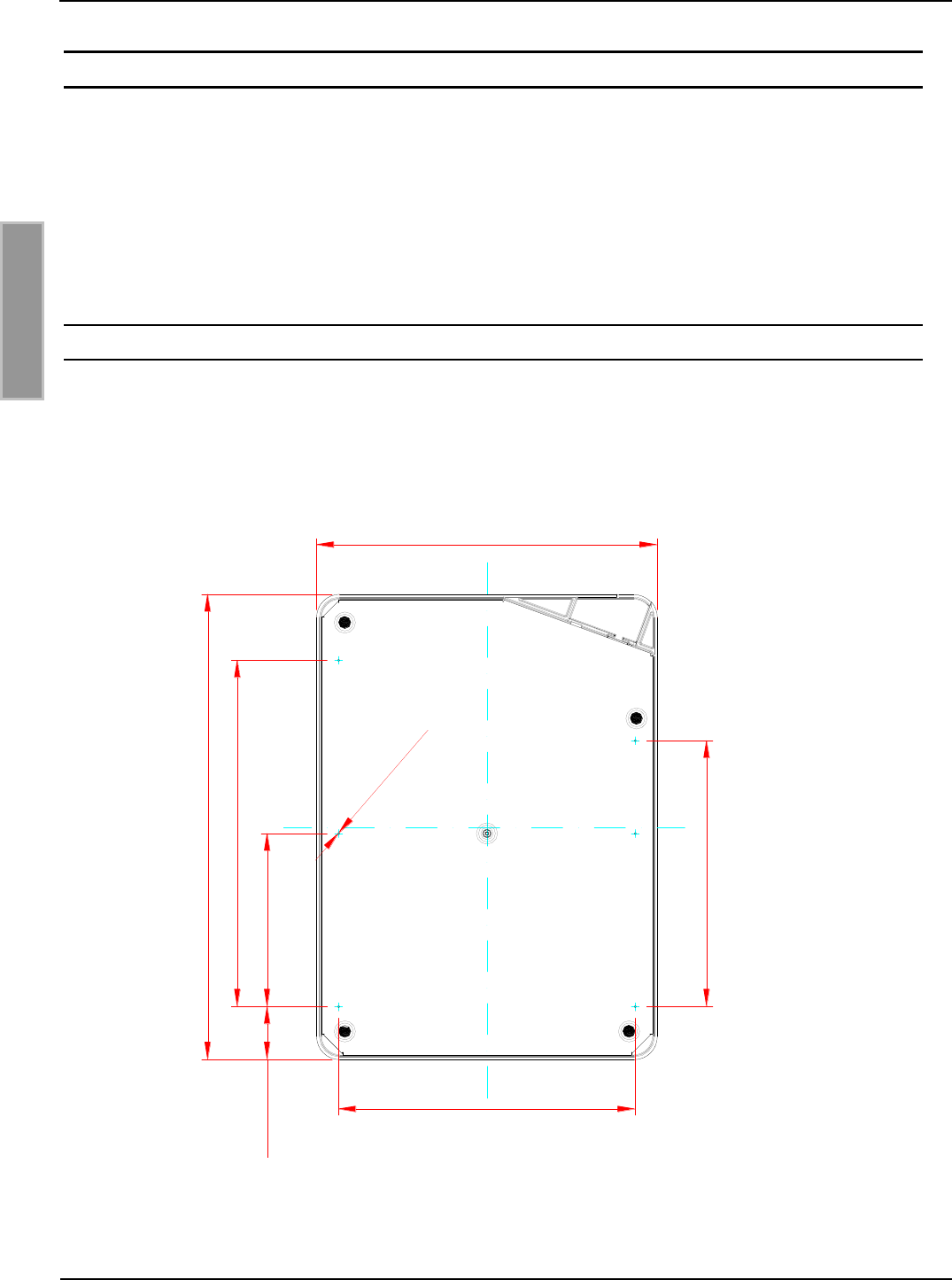
4.1.1 Versorgungsspannung über X1
Die Versorgungsspannung von 12 VDC wird an die DC-Buchse X1 angeschlossen. Die Bele-
gung des Steckers ist in folgender Tabelle aufgeführt:
Table 4-1: Pinbelegung Versorgungsspannung
Buchse
Kurzzeichen
Beschreibung
X1
X1 / innen
VDC
VDC – Versorgungsspannung (+)
X1 / außen
GND
Ground – Versorgungsspannung (-)
Hinweis:
Eine Verpolung der Versorgungsspannung kann zur Zerstörung des Gerätes führen.
Netzteilempfehlungen :
Zur Ausnutzung der vollständigen Leistungsfähigkeit des Readers sollte auf eine ausreichend sta-
bilisierte und rauscharme Spannungsversorgung geachtet werden. Bei der Verwendung eines
Schaltnetzteils ist darauf zu achten, dass die interne Schaltfrequenz des Netzteils unterhalb von
300 kHz liegt.
Table 4-2: Empfohlenes Netzteil
Artikel Nr.
Readertyp
Beschreibung
1688.002.00
ID NET.12V-B
Power Supply Unit 12 V
Bei allen Installation nach UL 60950 bzw. EN 60950 gilt:
Das Gerät muss mit einem „Listed NEC Class 2/LPS“ Netzteil versorgt werden
Bei Anschluss der Geräte mit flexiblen Leitungen sind im Besondern die Vorschriften nach
NEC Artikel 400.7 (8) und Artikel 400.8 (1) – (7) anzuwenden.
OBID i-scan®
Montage
ID ISC.SPAD102
FEIG ELECTRONIC GmbH
Seite 10 von 32
M10414-0de-ID-B_110711.doc
D E U T S C H
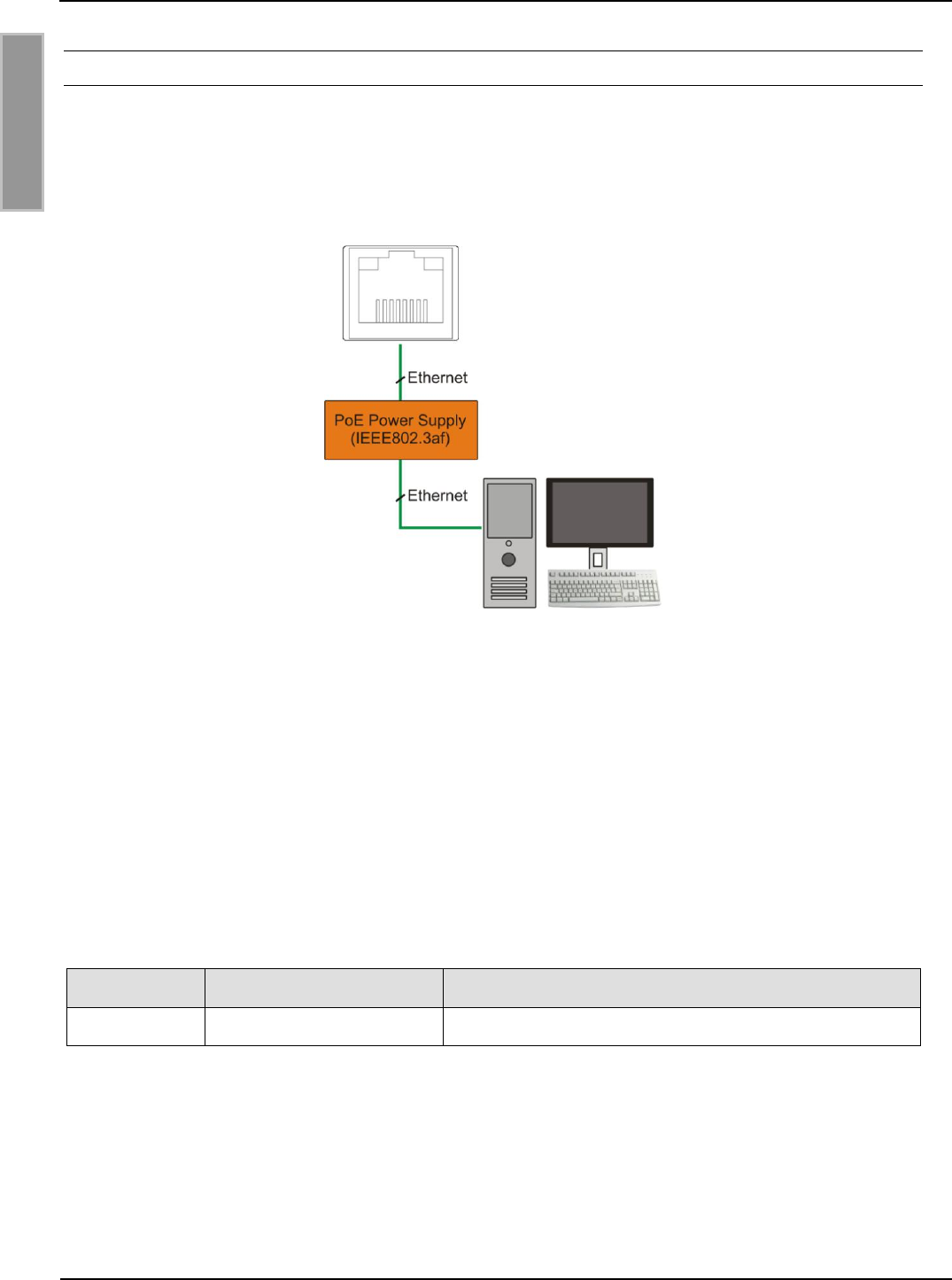
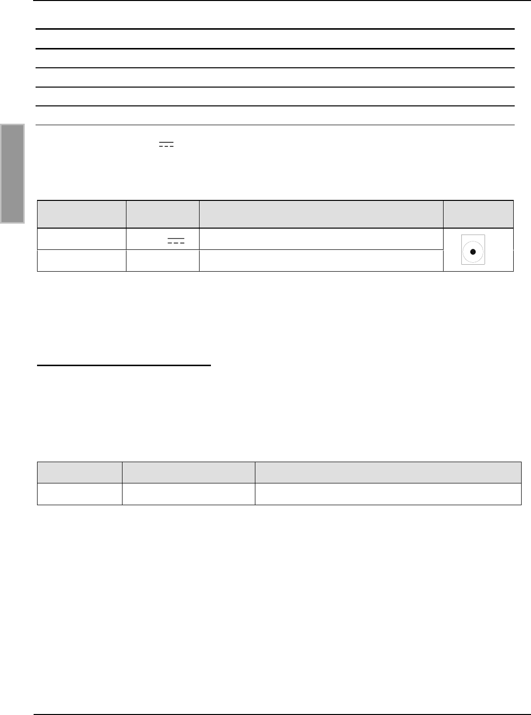
4.1.2 Versorgungsspannung über PoE (Power over Ethernet) (ID ISC.SPAD102-PoE)
Alternativ kann die PoE Variante über den LAN-Anschluss X4 mit Hilfe eines „Power over Ether-
net“-Netzteil gem. IEEE802.3af*, Class2 (6,49 Watt) versorgt werden. Die DC Speisung kann über
die freien Pin’s 4,5 und 7,8 erfolgen (Midspan-Power), als auch eine „Phantomspeisung“ über die
Signalverbindung 1,2,3 und 6 ist möglich (Inline-Power).
Abbildung 2: LAN und PoE Anschluss
Hinweis
Es ist sicherzustellen das der Reader mit mindestens 42,5 V (48 VDC – Leitungsverluste)
versorgt wird.
Die max. Leitungslänge für Ethernet ist 100m.
* Detaillierte technische Informationen zu dem Standard 802.3af können der aktuellen Version der
entsprechenden IEEE Spezifikation entnommen werden.
Table 4-3: Empfohlenes PoE Netzteil
Artikel Nr.
Readertyp
Beschreibung
0000.000.00
ID NET.PoE
Power over Ethernet Supply
X4
OBID i-scan®
Montage
ID ISC.SPAD102
FEIG ELECTRONIC GmbH
Seite 11 von 32
M10414-0de-ID-B_110711.doc
D E U T S C H
4.2 Schnittstellen
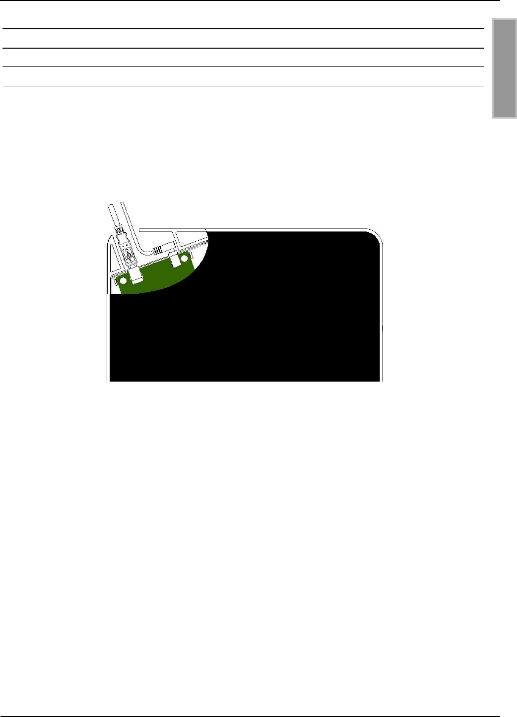
4.2.1 USB-Schnittstelle (ID ISC.SPAD102-USB)
Der Anschluss der USB-Schnittstelle erfolgt über Buchse X2. Die Belegung ist genormt. Die Daten-
rate des Readers ist auf 12 Mbit beschränkt (USB Full Speed). Es kann ein Standard-USB-Kabel
verwendet werden.
Der Anschluss der USB-Schnittstelle erfolgt über Buchse X3. Die Belegung ist genormt. Die Daten-
rate des Readers ist auf 12 Mbit beschränkt (USB Full Speed). Es kann ein Standard-USB-Kabel
verwendet werden.
Abbildung 3: USB-Schnittstelle für Host Kommunikation
Hinweis:
Die maximale Länge des USB-Kabels darf 5 m betragen. Längere Kabel sind nicht
zugelassen.
OBID i-scan®
Montage
ID ISC.SPAD102
FEIG ELECTRONIC GmbH
Seite 12 von 32
M10414-0de-ID-B_110711.doc
D E U T S C H
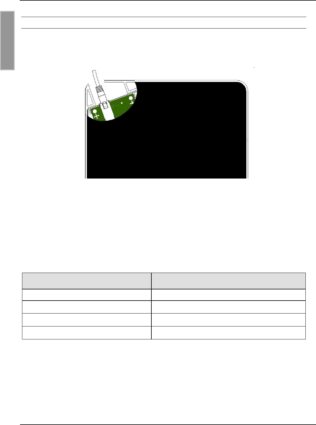
4.2.2 Ethernet-Schnittstelle (ID ISC.SPAD102-PoE)
Der Reader verfügt über eine integrierte 10/100 base-T Netzwerkschnittstelle mit Standard RJ-45-
Anschluss. Der Anschluss erfolgt über X2 und hat eine automatische „Crossover Detection“ ent-
sprechend dem 1000BASE-T Standard.
Abbildung 4: Anschluss Ethernet-Schnittstelle
Bei einer strukturierten Verkabelung sollten mindestens Kabel der Kategorie CAT5 verwendet wer-
den. Dies garantiert einen problemlosen Betrieb bei 10 Mbps oder 100 Mbps.
Vorraussetzung für den Einsatz des TCP/IP-Protokolls ist, dass jedes Gerät am Netzwerk über
eine eigene IP-Adresse verfügt. Alle Reader verfügen über eine werksseitig voreingestellte IP-
Adresse. Die Übertragungsparameter können per Softwareprotokoll konfiguriert werden.
Table 4-4: Werkskonfiguration der Ethernet-Schnittstelle
Netzwerk
Adresse
IP-Adresse
192.168.10.10
Subnet-Mask
255.255.255.0
Port
10001
DHCP
AUS
Hinweis:
Der Reader verfügt über eine DHCP-fähige TCP/IP Schnittstelle.

OBID i-scan®
Montage
ID ISC.SPAD102
FEIG ELECTRONIC GmbH
Seite 13 von 32
M10414-0de-ID-B_110711.doc
D E U T S C H
5 Anzeigeelement (LED)
Die blaue LED zeigt den Betriebszustand des Shielded Pad-Readers an:
Table 5-1: LED-Anzeige
LED-Signal
Beschreibung
LED blinkt nach Einschalten
Readersoftware wird gebootet
LED leuchtet
Sendeleistung 13,56 MHz eingeschaltet
LED blinkt
Transponder lesen
LED aus
Sendeleistung 13,56 MHz nicht eingeschaltet

OBID i-scan®
Montage
ID ISC.SPAD102
FEIG ELECTRONIC GmbH
Seite 14 von 32
M10414-0de-ID-B_110711.doc
D E U T S C H
6 Technische Daten
Mechanische Daten
Gehäuse
- Oberteil
- Abdeckplatte
- Unterteil
- Kunststoff ABS
- Acrylglas
- Stahlblech verzinkt
Abmessungen (B x H x T)
376 x 276 x 26,8 mm³
Gewicht
ca. 2,0 kg
Schutzart
IP 30
Farbe
- Gehäuse
- Abdeckplatte
- ähnlich RAL 9003 (weiß)
- Transparent, schwarz hinterdruckt
Elektrische Daten
Spannungsversorgung
- 12..24 VDC 15 %
- PoE (nur ID ISC.SPAD102-PoE)
Leistungsaufnahme
max. 6 VA
Betriebsfrequenz
13,56 MHz
Sendeleistung
1,5 W ± 1 dB
Schnittstellen
- Ethernet (TCP/IP) (ID ISC.SPAD102-PoE)
- USB (ID ISC.SPAD102-USB)
Protokoll Modi
- ISO Host Mode
- Scan Mode
- Notification Mode
Unterstützte Transponder
ISO15693, ISO18000-3 Mode 1
(EM HF ISO Chips, Fujitsu HF ISO Chips, KSW
Sensor Chips, IDS Sensor Chips,
Infineon my-d, NXP I-Code, STM LRI ISO Chips,
TI Tag-it)
Signalgeber optisch
LED blau (Betriebszustand)

OBID i-scan®
Montage
ID ISC.SPAD102
FEIG ELECTRONIC GmbH
Seite 15 von 32
M10414-0de-ID-B_110711.doc
D E U T S C H
Umgebungsbedingungen
Temperaturbereich
- Betrieb
- Lagerung
-25...+55°C
-25...+85°C
Relative Luftfeuchtigkeit
5 bis 95% nicht betauend
Angewendete Normen
Zulassung Funk
- Europa
- USA
- Kanada
- EN 300 330
- FCC 47 CFR Part 15
- RSS-Gen Issue 1, RSS-210
EMV
EN 301 489
Sicherheit
- Niederspannung
- Human Exposure
EN 60950
EN 50364
OBID i-scan®
Montage
ID ISC.SPAD102
FEIG ELECTRONIC GmbH
Seite 16 von 32
M10414-0de-ID-B_110711.doc
D E U T S C H
6.1 Zulassung
6.1.1 Europa (CE)
Die Funkanlage entspricht, bei bestimmungsgemäßer Verwendung den grundlegenden Anforde-
rungen des Artikels 3 und den übrigen einschlägigen Bestimmungen der R&TTE Richtlinie
1999/5/EG vom März 99.
Equipment Classification gemäß ETSI EN 301 489: Class 2

OBID i-scan®
Montage
ID ISC.SPAD102
FEIG ELECTRONIC GmbH
Seite 17 von 32
M10414-0de-ID-B_110711.doc
D E U T S C H
6.1.2 USA und Kanada
Product names:
ID ISC.SPAD102-USB, ID ISC.SPAD102-PoE
Reader name:
ID ISC.MR102
FCC ID:
IC:
PJMMR102
6633A-MR102
Notice for USA and
Canada
This device complies with Part 15 of the FCC Rules and with
RSS-210 of Industry Canada.
Operation is subject to the following two conditions.
(1) this device may not cause harmful interference, and
(2) this device must accept any interference received,
including interference that may cause undesired operation.
Unauthorized modifications may void the authority granted under
Federal communications Commission Rules permitting the operation
of this device.
This equipment has been tested and found to comply with the limits for
a Class A digital device, pursuant to Part 15 of the FCC Rules. These
limits are designed to provide reasonable protection against harmful
interference when the equipment is operated in a commercial
environment. This equipment generates, uses, and can radiate radio
frequency energy and, if not installed and used in accordance with the
instruction manual, may cause harmful interference to radio
communications. Operation of this equipment in a residential area is
likely to cause harmful interference in which case the user will be
required to correct the interference at his own expense.
Le présent appareil est conforme aux CNR d'Industrie Canada appli-
cables aux appareils radio exempts de licence. L'exploitation est auto-
risée aux deux conditions suivantes :
(1) l'appareil ne doit pas produire de brouillage, et
(2) l'utilisateur de l'appareil doit accepter tout brouillage radioélectrique
subi, même si le brouillage est susceptible d'en compromettre le fonc-
tionnement.
Warning: Changes or modification made to this equipment not expressly approved by
FEIG ELECTRONIC GmbH may void the FCC authorization to operate this equipment.

OBID i-scan®
Installation
ID ISC.SPAD102
FEIG ELECTRONIC GmbH
Page 18 of 32
M10414-0de-ID-B_110711.doc
E N G L I S H
Note
Copyright 2011 by
FEIG ELECTRONIC GmbH
Lange Strasse 4
D-35781 Weilburg
Tel.: +49 6471 3109-0
http://www.feig.de
With the edition of this document, all previous editions become void. Indications made in this manual may be
changed without previous notice.
Copying of this document, and giving it to others and the use or communication of the contents thereof are
forbidden without express authority. Offenders are liable to the payment of damages. All rights are reserved
in the event of the grant of a patent or the registration of a utility model or design.
Composition of the information in this document has been done to the best of our knowledge. FEIG
ELECTRONIC GmbH does not guarantee the correctness and completeness of the details given in this ma-
nual and may not be held liable for damages ensuing from incorrect or incomplete information. Since, despite
all our efforts, errors may not be completely avoided, we are always grateful for your useful tips.
The instructions given in this manual are based on advantageous boundary conditions. FEIG ELECTRONIC
GmbH does not give any guarantee promise for perfect function in cross environments.
FEIG call explicit attention that devices which are subject of this document are not designed with compo-
nents and testing methods for a level of reliability suitable for use in or in connection with surgical implants or
as critical components in any life support systems whose failure to perform can reasonably be expected to
cause significant injury to a human. To avoid damage, injury, or death, the user or application designer must
take reasonably prudent steps to protect against system failures.
FEIG ELECTRONIC GmbH assumes no responsibility for the use of any information contained in this docu-
ment and makes no representation that they free of patent infringement. FEIG ELECTRONIC GmbH does
not convey any license under its patent rights nor the rights of others.
OBID® and OBID i-scan® are registered trademarks of FEIG ELECTRONIC GmbH.

OBID i-scan®
Installation
ID ISC.SPAD102
FEIG ELECTRONIC GmbH
Page 19 of 32
M10414-0de-ID-B_110711.doc
E N G L I S H
Content
7 Safety Instructions / Warning - Read before start-up ! 20
8 Performance Features 21
8.1 Order Reference ........................................................................................................ 21
8.2 Scope of delivery ...................................................................................................... 21
9 Assembly and Wiring 22
9.1 Dimensions ............................................................................................................... 22
9.2 Mounting under a desktop ....................................................................................... 23
10 Connections 24
10.1 Power supply ............................................................................................................ 24
10.1.1 Power supply via X1 ............................................................................................... 24
Power supply recommendations : 24
10.1.2 Power supply via PoE (Power over Ethernet) on X4 (ID ISC.SPAD102-PoE) ......... 25
10.2 Interfaces ................................................................................................................... 26
10.2.1 USB-Interface (ID ISC.SPAD102-USB) .................................................................. 26
10.2.2 Ethernet-Interface (ID ISC.SPAD102-PoE) ............................................................ 27
11 Display (LED) 28
12 Technical Data 29
12.1 Approvals .................................................................................................................. 31
12.1.1 Europe (CE) ........................................................................................................... 31
12.1.2 USA (FCC) and Canada (IC) .................................................................................. 32

OBID i-scan®
Installation
ID ISC.SPAD102
FEIG ELECTRONIC GmbH
Page 20 of 32
M10414-0de-ID-B_110711.doc
E N G L I S H
7 Safety Instructions / Warning - Read before start-up !
The device may only be used for the intended purpose designed by for the manufacturer.
The operation manual should be conveniently kept available at all times for each user.
Unauthorized changes and the use of spare parts and additional devices which have not been
sold or recommended by the manufacturer may cause fire, electric shocks or injuries. Such
unauthorized measures shall exclude any liability by the manufacturer.
The liability-prescriptions of the manufacturer in the issue valid at the time of purchase are valid
for the device. The manufacturer shall not be held legally responsible for inaccuracies, errors,
or omissions in the manual or automatically set parameters for a device or for an incorrect
application of a device.
Repairs may only be executed by the manufacturer.
Installation, operation, and maintenance procedures should only be carried out by qualified
personnel.
Use of the device and its installation must be in accordance with national legal requirements
and local electrical codes .
When working on devices the valid safety regulations must be observed.
Special advice for carriers of cardiac pacemakers:
Although this device doesn't exceed the valid limits for electromagnetic fields you should
keep a minimum distance of 25 cm between the device and your cardiac pacemaker and not
stay in an immediate proximity of the device respective the antenna for some time.
OBID i-scan®
Installation
ID ISC.SPAD102
FEIG ELECTRONIC GmbH
Page 21 of 32
M10414-0de-ID-B_110711.doc
E N G L I S H
8 Performance Features
The Shielded Pad Reader ID ISC.SPAD102 is designed for reading passive data carriers, so-
called „Smart Labels“ at an operating frequency of 13.56 MHz with a maximum output power of
1,5 W. The ID ISC.SPAD102 is suitable for all applications in which moderate reading distances
are required. A shielded antenna and a reader is integrated in a plastic housing.
Due to the shielding the communication with the transponder is widely limited on the top area oft
the antenna.
The possibility to place the antenna ID ISC.SPAD102 directly on metal without changing the an-
tenna parameter is a second essential advantage of this antenna.
An anti-collision function enables simultaneous reading of up to 30 transponders per second.
The antenna may be used for detecting both product or persons. The preferred orientation of a
Smart Label is parallel to the antenna surface. The maximum range is achieved over the center of
the antenna surface.
8.1 Order Reference
The following variants are available currently:
Table 8-1: Order reference Shielded Pad-Reader
Order No.
Name
Description
3756.000.00
ID ISC.SPAD102-USB
Shielded Pad Reader with USB Interface
3513.000.00
ID ISC.SPAD102-PoE
Shielded Pad Reader with Ethernet Interface (PoE)
8.2 Scope of delivery
Within the scope of delivery the reader ID ISC.SPAD102 came including connection cable
assembly and mounting instruction.
OBID i-scan®
Installation
ID ISC.SPAD102
FEIG ELECTRONIC GmbH
Page 22 of 32
M10414-0de-ID-B_110711.doc
E N G L I S H
9 Assembly and Wiring
The antenna is intended for the indoor use on a plane surface (desktop) or for the mounting behind
or under a mounting plate (non-conductive).
For the operation on a plane surface rubber bumper are mounted on the backside of the antenna.
The mounting behind or under a mounting plate can take place via domes, which are suggested
with bore holes on the backside of the antenna housing.
9.1 Dimensions
The dimensions and the mounting holes of the shielded pad antenna are shown in the following
picture.
All dimensions are shown in mm (inch):
376,2 (14,81)
275,7 (10,85)
280 (11,02)
215 (8,46)
140 ( 5,51)42,8 (1,68)
240 (9,44)
6 x Ø 1,5 (0,06)
Figure 1: Dimensions of the antenna and positions of mounting holes (backside)

OBID i-scan®
Installation
ID ISC.SPAD102
FEIG ELECTRONIC GmbH
Page 23 of 32
M10414-0de-ID-B_110711.doc
E N G L I S H
9.2 Mounting under a desktop
For the mounting under a desktop or a mounting plate the mounting holes (max. 4mm) must be
drilled. The position of the mounting holes are suggested via 1,5mm drill holes in the housing
backside of the antenna (see figure 1). Drill holes on a different place can destroy the antenna.
OBID i-scan®
Installation
ID ISC.SPAD102
FEIG ELECTRONIC GmbH
Page 24 of 32
M10414-0de-ID-B_110711.doc
E N G L I S H
10 Connections
10.1 Power supply
10.1.1 Power supply via X1
Connect the 12-24 V DC/ supply voltage to socket X1 on the circuit board.
Table 10-1: Connecting the supply voltage
Terminal
Name
Description
X 1
X1 / inside
VDC
Vcc – supply voltage (+)
X1 / outside
GND
Ground – supply voltage (-)
Note:
Reversing the polarity of the supply voltage may destroy the device.
Power supply recommendations :
To take full advantage of the Reader performance, you must use a sufficiently regulated and low-
noise power supply. When using a switching power supply, be sure that its internal switching fre-
quency is less than 300 kHz.
Table 10-2: Recommended power supply:
Feig Article No
Part No.
Description.
1688.002.00
ID NET.12V-B
Power Supply Unit 12 V
OBID i-scan®
Installation
ID ISC.SPAD102
FEIG ELECTRONIC GmbH
Page 25 of 32
M10414-0de-ID-B_110711.doc
E N G L I S H
10.1.2 Power supply via PoE (Power over Ethernet) on X4 (ID ISC.SPAD102-PoE)
Optional the reader (only MR102-PoE) can be powered via the LAN connector on X4 with the use
of a PoE „Power over Ethernet“ power supply according to IEEE802.3af*, Class2 (6,49 Watt).
The DC supply can be achieved via the free pin’s 4,5 and 7,8 (Midspan-Power). Also a “Phantom
Powering” (Inline-Power) via the signal pin’s 1,2,3,and 6 is possible.
Figure 2: LAN and PoE connection
Note:
It must be ensured that the reader is supplied with 42,5 V DC (48 V DC – cable losses) at
least.
The maximum cable distance for Ethernet is 100m.
* For detailed technical information regarding the 802.3af standard, please refer to the most
recent edition of the corresponding IEEE specification.
Table 10-3: Recommended PoE Power Supply
Article No.
Name
Description
0000.000.00
ID NET.PoE
Power over Ethernet Supply
X4

OBID i-scan®
Installation
ID ISC.SPAD102
FEIG ELECTRONIC GmbH
Page 26 of 32
M10414-0de-ID-B_110711.doc
E N G L I S H
10.2 Interfaces
10.2.1 USB-Interface (ID ISC.SPAD102-USB)
There is a USB-socket X3 on board for the connection of the USB-Interface. The pinout is standar-
dized. The data rate is reduced to 12 Mbit (USB full speed). A standard USB-cable can be used..
Figure 3: USB-Interface for host communication
Note:
The length of the USB-cable can be a max. of 5 meter. It isn’t allowed to use longer cables!

OBID i-scan®
Installation
ID ISC.SPAD102
FEIG ELECTRONIC GmbH
Page 27 of 32
M10414-0de-ID-B_110711.doc
E N G L I S H
10.2.2 Ethernet-Interface (ID ISC.SPAD102-PoE)
The Reader has an integrated 10 / 100 base-T network port for an RJ-45. Connection is made on
X2 and has an automatic “Crossover Detection” according to the 100BASE-T Standard.
Abbildung 5: Anschluss Ethernet-Schnittstelle
With structured cabling CAT 5 cables should be used. This ensures a reliable operation at 10 Mbps
or 100 Mbps.
The prerequisite for using TCP/IP protocol is that each device has a unique address on the net-
work. All Readers have a factory set IP address. Interface parameter can be configured via soft-
ware protocol
Table 10-4: Standard factory configuration of the Ethernet connection
Network
Address
IP-Address
192.168.10.10
Subnet-Mask
255.255.255.0
Port
10001
DHCP
OFF
Note:
The reader provides a DHCP able TCP/IP interface.
OBID i-scan®
Installation
ID ISC.SPAD102
FEIG ELECTRONIC GmbH
Page 28 of 32
M10414-0de-ID-B_110711.doc
E N G L I S H
11 Display (LED)
The blue LED indicates the operating status of the Shielded Pad-Readers:
Table 11-1: LED-Display
LED-Signal
Description
LED flashes after power on
Reader software will be booted
LED on
RF power 13,56 MHz switched on
LED flash
Reading transponder
LED off
RF power 13,56 MHz switched off

OBID i-scan®
Installation
ID ISC.SPAD102
FEIG ELECTRONIC GmbH
Page 29 of 32
M10414-0de-ID-B_110711.doc
E N G L I S H
12 Technical Data
Mechanical Data
Housing
- Upper Part
- Cover Plate
- Lower Part
- Plastic ABS
- Acryl glass
- Galvanized metal sheet
Dimension (W x H x D)
376 x 276 x 26,8 mm³
(14,8 x 10,87 x 1,06 inch³)
Weight
ca. 2,0 kg
Protection class
IP 30
Color
- Housing
- Cover Plate
- similar RAL 9003 (white)
- Transparent, black Screen back printed
Electrical Data
Power supply
- 12..24 VDC 15 %
- PoE (ID ISC.SPAD102-PoE only)
Power consumption
max. 6 VA
Operating frequency
13,56 MHz
Transmitting power
1,5 W ± 1 dB
Interface
- Ethernet (TCP/IP) (ID ISC.SPAD102-PoE)
- USB (ID ISC.SPAD102-USB)
Protocol Modes
- ISO Host Mode
- Scan Mode
- Notification Mode
Supported Transponder
ISO15693, ISO18000-3 Mode 1
(EM HF ISO Chips, Fujitsu HF ISO Chips, KSW
Sensor Chips, IDS Sensor Chips,
Infineon my-d, NXP I-Code, STM LRI ISO Chips,
TI Tag-it)
Visual indicators
LED blue (Operating status)

OBID i-scan®
Installation
ID ISC.SPAD102
FEIG ELECTRONIC GmbH
Page 30 of 32
M10414-0de-ID-B_110711.doc
E N G L I S H
Ambient Conditions
Temperature range
- Operation
- Storage
-25°C to +55°C / -13°F to +131°F
-25°C to +85°C / -13°F to +185°F
Humidity
5 – 95% non condensing
Applicable Norms
Radio approval
- Europe
- USA
- Canada
- EN 300 330
- FCC 47 CFR Part 15
- RSS-Gen Issue 1, RSS-210
EMC
EN 301 489
Safety
- Low-Voltage
- Human Exposure
EN 60950
EN 50364

OBID i-scan®
Installation
ID ISC.SPAD102
FEIG ELECTRONIC GmbH
Page 31 of 32
M10414-0de-ID-B_110711.doc
E N G L I S H
12.1 Approvals
12.1.1 Europe (CE)
This RF equipment is in compliance with the essential requirements and other relevant provisions
of Directive 1999/5/EC dated March 99.
Equipment Classification according to ETSI EN 300 330 and ETSI EN 301 489: Class 2

OBID i-scan®
Installation
ID ISC.SPAD102
FEIG ELECTRONIC GmbH
Page 32 of 32
M10414-0de-ID-B_110711.doc
E N G L I S H
12.1.2 USA (FCC) and Canada (IC)
Product names:
ID ISC.SPAD102-USB, ID ISC.SPAD102-PoE
Reader name:
ID ISC.MR102
FCC ID:
IC:
PJMMR102
6633A-MR102
Notice for USA and
Canada
This device complies with Part 15 of the FCC Rules and with
RSS-210 of Industry Canada.
Operation is subject to the following two conditions.
(1) this device may not cause harmful interference, and
(2) this device must accept any interference received,
including interference that may cause undesired operation.
Unauthorized modifications may void the authority granted under
Federal communications Commission Rules permitting the operation
of this device.
This equipment has been tested and found to comply with the limits for
a Class A digital device, pursuant to Part 15 of the FCC Rules. These
limits are designed to provide reasonable protection against harmful
interference when the equipment is operated in a commercial
environment. This equipment generates, uses, and can radiate radio
frequency energy and, if not installed and used in accordance with the
instruction manual, may cause harmful interference to radio
communications. Operation of this equipment in a residential area is
likely to cause harmful interference in which case the user will be
required to correct the interference at his own expense.
Le présent appareil est conforme aux CNR d'Industrie Canada appli-
cables aux appareils radio exempts de licence. L'exploitation est auto-
risée aux deux conditions suivantes :
(1) l'appareil ne doit pas produire de brouillage, et
(2) l'utilisateur de l'appareil doit accepter tout brouillage radioélectrique
subi, même si le brouillage est susceptible d'en compromettre le fonc-
tionnement.
Warning: Changes or modification made to this equipment not expressly approved by
FEIG ELECTRONIC GmbH may void the FCC authorization to operate this equipment.