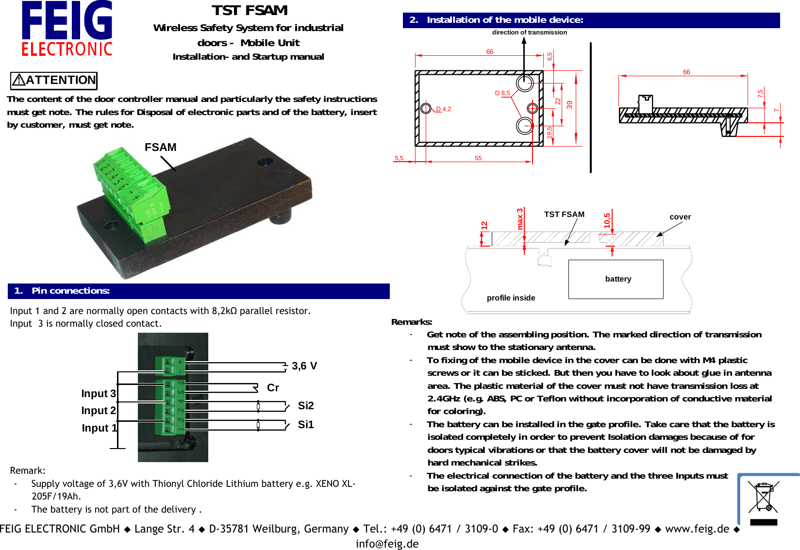
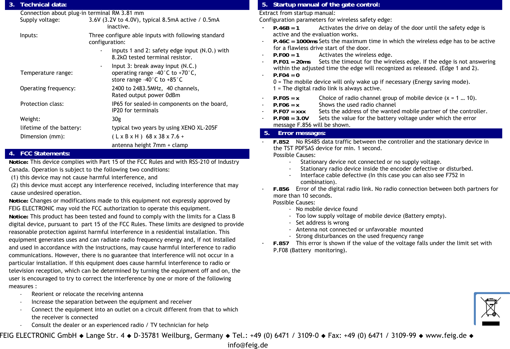
Feig Electronic TSTFSAM Wireless Safety System for industrial doors - Mobile Unit User Manual

Feig Electronic GmbH Wireless Safety System for industrial doors - Mobile Unit

User Manual

FEIG ELECTRONIC GmbH  Lange Str. 4  D-35781 Weilburg, Germany  Tel.: +49 (0) 6471 / 3109-0  Fax: +49 (0) 6471 / 3109-99  www.feig.de  Email:info@feig.deTST FSAMWireless Safety System for industrialdoors -  Mobile UnitInstallation- and Startup manual!ATTENTIONThe content of the door controller manual and particularly the safety instructionsmust get note. The rules for Disposal of electronic parts and of the battery, insertby customer, must get note.FSAM1. Pin connections:Input 1 and 2 are normally open contacts with 8,2kΩ parallel resistor.Input  3 is normally closed contact.3,6 VCrSi2Si1Input 1Input 2Input 3Remark:- Supply voltage of 3,6V with Thionyl Chloride Lithium battery e.g. XENO XL-205F/19Ah.- The battery is not part of the delivery .2. Installation of the mobile device:662266direction of transmission39D 4,2D 8,5555,519,57,576,5batteryprofile insidemax 312TST FSAM cover10,5Remarks:- Get note of the assembling position. The marked direction of transmissionmust show to the stationary antenna.- To fixing of the mobile device in the cover can be done with M4 plasticscrews or it can be sticked. But then you have to look about glue in antennaarea. The plastic material of the cover must not have transmission loss at2.4GHz (e.g. ABS, PC or Teflon without incorporation of conductive materialfor coloring).- The battery can be installed in the gate profile. Take care that the battery isisolated completely in order to prevent Isolation damages because of fordoors typical vibrations or that the battery cover will not be damaged byhard mechanical strikes.- The electrical connection of the battery and the three Inputs mustbe isolated against the gate profile.
FEIG ELECTRONIC GmbH  Lange Str. 4  D-35781 Weilburg, Germany  Tel.: +49 (0) 6471 / 3109-0  Fax: +49 (0) 6471 / 3109-99  www.feig.de  Email:info@feig.de3. Technical data:Connection about plug-in terminal RM 3.81 mmSupply voltage: 3.6V (3.2V to 4.0V), typical 8.5mA active / 0.5mA                                  inactive.Inputs: Three configure able inputs with following standard configuration:- inputs 1 and 2: safety edge input (N.O.) with8.2kΩ tested terminal resistor.- Input 3: break away input (N.C.)Temperature range:  operating range –40°C to +70°C,store range –40°C to +85°COperating frequency: 2400 to 2483.5MHz,  40 channels,Rated output power 0dBmProtection class:  IP65 for sealed-in components on the board,IP20 for terminalsWeight:  30glifetime of the battery: typical two years by using XENO XL-205FDimension (mm):   ( L x B x H )  68 x 38 x 7.6 +antenna height 7mm + clamp4. FCC Statements:Notice: This device complies with Part 15 of the FCC Rules and with RSS-210 of IndustryCanada. Operation is subject to the following two conditions:(1) this device may not cause harmful interference, and(2) this device must accept any interference received, including interference that maycause undesired operation.Notice: Changes or modifications made to this equipment not expressly approved byFEIG ELECTRONIC may void the FCC authorization to operate this equipment.Notice: This product has been tested and found to comply with the limits for a Class Bdigital device, pursuant to  part 15 of the FCC Rules. These limits are designed to providereasonable protection against harmful interference in a residential installation. Thisequipment generates uses and can radiate radio frequency energy and, if not installedand used in accordance with the instructions, may cause harmful interference to radiocommunications. However, there is no guarantee that interference will not occur in aparticular installation. If this equipment does cause harmful interference to radio ortelevision reception, which can be determined by turning the equipment off and on, theuser is encouraged to try to correct the interference by one or more of the followingmeasures :- Reorient or relocate the receiving antenna- Increase the separation between the equipment and receiver- Connect the equipment into an outlet on a circuit different from that to whichthe receiver is connected- Consult the dealer or an experienced radio / TV technician for help5. Startup manual of the gate control:Extract from startup manual:Configuration parameters for wireless safety edge:- P.46B = 1 Activates the drive on delay of the door until the safety edge isactive and the evaluation works.- P.46C = 1000ms Sets the maximum time in which the wireless edge has to be activefor a flawless drive start of the door.- P.F00 = 1 Activates the wireless edge.- P.F01 = 20ms Sets the timeout for the wireless edge. If the edge is not answeringwithin the adjusted time the edge will recognized as released. (Edge 1 and 2).- P.F04 = 00 = The mobile device will only wake up if necessary (Energy saving mode).1 = The digital radio link is always active.- P.F05 = x Choice of radio channel group of mobile device (x = 1 … 10).- P.F06 = x Shows the used radio channel- P.F07 = xxx Sets the address of the wanted mobile partner of the controller.- P.F08 = 3.0V Sets the value for the battery voltage under which the errormessage F.856 will be shown.5.    Error messages:- F.852 No RS485 data traffic between the controller and the stationary device inthe TST PDFSAS device for min. 1 second.Possible Causes:- Stationary device not connected or no supply voltage.- Stationary radio device inside the encoder defective or disturbed.- Interface cable defective (In this case you can also see F752 incombination).- F.856 Error of the digital radio link. No radio connection between both partners formore than 10 seconds.Possible Causes:- No mobile device found- Too low supply voltage of mobile device (Battery empty).- Set address is wrong- Antenna not connected or unfavorable  mounted- Strong disturbances on the used frequency range- F.857 This error is shown if the value of the voltage falls under the limit set withP.F08 (Battery  monitoring).

Navigation menu