Feig Electronic TSTFSAMK Wireless Safety System for industrial doors User Manual UserManual
Feig Electronic GmbH Wireless Safety System for industrial doors UserManual
Contents
- 1. UserManual.pdf
- 2. User Manual
UserManual.pdf
FEIGELECTRONICGmbHLangeStr.4D‐35781Weilburg,GermanyTel.:+49(0)6471/3109‐0Fax:+49(0)6471/3109‐99www.feig.deEmail:info@feig.de
TSTFSAM 250KBit
WirelessSafetySystemforindustrial
doors‐MobileUnit
Installation‐andStartupmanual
!ATTENTION
Thecontentofthedoorcontrollermanualandparticularlythesafetyinstructionsmustget
note.TherulesforDisposalofelectronicpartsandofthebattery,insertbycustomer,must
getnote.
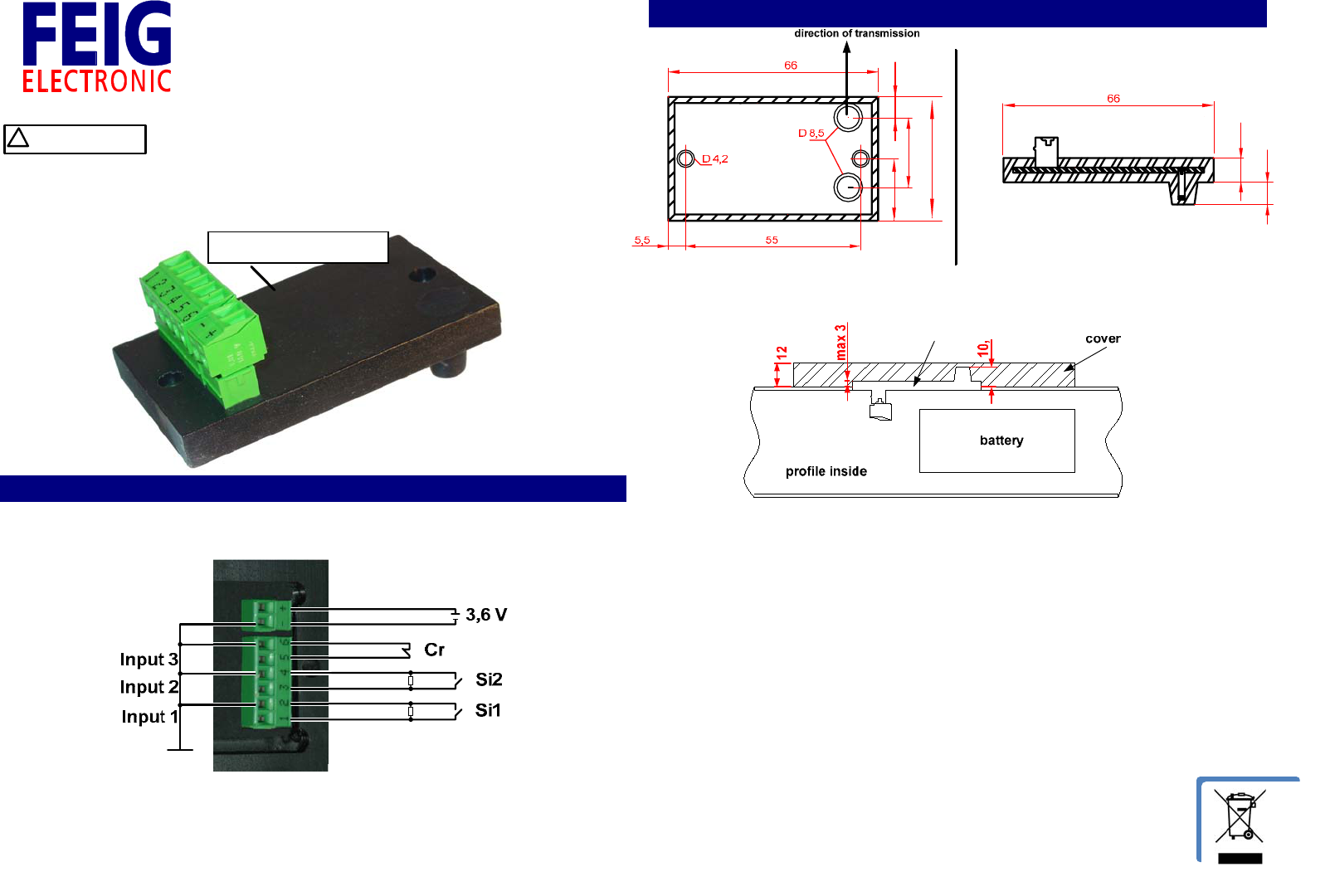
1. Pinconnections:
Input1and2arenormallyopencontactswith8,2kΩparallelresistor.
Input3isnormallyclosedcontact.
Remark:
‐ Supplyvoltageof3,6VwithThionylChlorideLithiumbatterye.g.XENOXL‐205F/19Ah.
‐ Thebatteryisnotpartofthedelivery.
2. Installationofthemobiledevice:
22
39
19,5
7,5
7
6,5
Remarks:
‐ Getnoteoftheassemblingposition.Themarkeddirectionoftransmissionmustshow
tothestationaryantenna.
‐ TofixingofthemobiledeviceinthecovercanbedonewithM4plasticscrewsoritcan
besticked.Butthenyouhavetolookaboutglueinantennaarea.Theplasticmaterial
ofthecovermustnothavetransmissionlossat2.4GHz(e.g.ABS,PCorTeflonwithout
incorporationofconductivematerialforcoloring).
‐ Thebatterycanbeinstalledinthegateprofile.Takecarethatthebatteryisisolated
completelyinordertopreventIsolationdamagesbecauseoffordoorstypical
vibrationsorthatthebatterycoverwillnotbedamagedbyhardmechanicalstrikes.
‐ TheelectricalconnectionofthebatteryandthethreeInputsmustbeisolatedagainst
thegateprofile.
TST FSAM 250 KBit
TST FSAM 250 KBit

FEIGELECTRONICGmbHLangeStr.4D‐35781Weilburg,GermanyTel.:+49(0)6471/3109‐0Fax:+49(0)6471/3109‐99www.feig.deEmail:info@feig.de
3. Technicaldata:
Connectionaboutplug‐interminalRM3.81mm
Supplyvoltage:3.6V(3.2Vto4.0V),typical8.5mAactive/0.5mA
inactive.
Inputs:Threeconfigureableinputswithfollowingstandard
configuration:
‐ inputs1and2:safetyedgeinput(N.O.)with8.2kΩ
testedterminalresistor.
‐ Input3:breakawayinput(N.C.)
Temperaturerange: operatingrange–40°Cto+70°C,
storerange–40°Cto+85°C
Operatingfrequency: 2400to2483.5MHz,40channels,
Ratedoutputpower0dBm
Protectionclass: IP65forsealed‐incomponentsontheboard,
IP20forterminals
Weight: 30g
lifetimeofthebattery: typicaltwoyearsbyusingXENOXL‐205F
Dimension(mm): (LxBxH)68x38x7.6+
antennaheight7mm+clamp
4. FCCStatements:
Notice:ThisdevicecomplieswithPart15oftheFCCRulesandwithRSS‐210ofIndustryCanada.
Operationissubjecttothefollowingtwoconditions:
(1)thisdevicemaynotcauseharmfulinterference,and
(2)thisdevicemustacceptanyinterferencereceived,includinginterferencethatmaycause
undesiredoperation.
Notice:Changesormodificationsmadetothisequipmentnotexpresslyapprovedby
FEIGELECTRONICmayvoidtheFCCauthorizationtooperatethisequipment.
Notice:ThisproducthasbeentestedandfoundtocomplywiththelimitsforaClassBdigital
device,pursuanttopart15oftheFCCRules.Theselimitsaredesignedtoprovidereasonable
protectionagainstharmfulinterferenceinaresidentialinstallation.Thisequipmentgeneratesuses
andcanradiateradiofrequencyenergyand,ifnotinstalledandusedinaccordancewiththe
instructions,maycauseharmfulinterferencetoradiocommunications.However,thereisno
guaranteethatinterferencewillnotoccurinaparticularinstallation.Ifthisequipmentdoescause
harmfulinterferencetoradioortelevisionreception,whichcanbedeterminedbyturningthe
equipmentoffandon,theuserisencouragedtotrytocorrecttheinterferencebyoneormoreof
thefollowingmeasures:
‐ Reorientorrelocatethereceivingantenna
‐ Increasetheseparationbetweentheequipmentandreceiver
‐ Connecttheequipmentintoanoutletonacircuitdifferentfromthattowhichthe
receiverisconnected
‐ Consultthedealeroranexperiencedradio/TVtechnicianforhelp
5. Startupmanualofthegatecontrol:
Extractfromstartupmanual:
Configurationparametersforwirelesssafetyedge:
‐ P.46B=1Activatesthedriveondelayofthedooruntilthesafetyedgeis
activeandtheevaluationworks.
‐ P.46C=1000msSetsthemaximumtimeinwhichthewirelessedgehastobeactivefora
flawlessdrivestartofthedoor.
‐ P.F00=1Activatesthewirelessedge.
‐ P.F01=20msSetsthetimeoutforthewirelessedge.Iftheedgeisnotansweringwithin
theadjustedtimetheedgewillrecognizedasreleased.(Edge1and2).
‐ P.F04=0
0=Themobiledevicewillonlywakeupifnecessary(Energysavingmode).
1=Thedigitalradiolinkisalwaysactive.
‐ P.F05=xChoiceofradiochannelgroupofmobiledevice(x=1…10).
‐ P.F06=xShowstheusedradiochannel
‐ P.F07=xxxSetstheaddressofthewantedmobilepartnerofthecontroller.
‐ P.F08=3.0VSetsthevalueforthebatteryvoltageunderwhichtheerrormessageF.856
willbeshown.
5.Errormessages:
‐ F.852NoRS485datatrafficbetweenthecontrollerandthestationarydeviceintheTST
PDFSASdeviceformin.1second.
PossibleCauses:
‐ Stationarydevicenotconnectedornosupplyvoltage.
‐ Stationaryradiodeviceinsidetheencoderdefectiveordisturbed.
‐ Interfacecabledefective(InthiscaseyoucanalsoseeF752incombination).
‐ F.856Errorofthedigitalradiolink.Noradioconnectionbetweenbothpartnersformore
than10seconds.
PossibleCauses:
‐ Nomobiledevicefound
‐ Toolowsupplyvoltageofmobiledevice(Batteryempty).
‐ Setaddressiswrong
‐ Antennanotconnectedorunfavorablemounted
‐ Strongdisturbancesontheusedfrequencyrange
‐ F.857ThiserrorisshownifthevalueofthevoltagefallsunderthelimitsetwithP.F08
(Batterymonitoring).