Fibar Group FGD212 Dimmer 2 User Manual 20151218 v1 6 CONFIDENTIAL FGD 212 US T v1 0 Operating Manual
Fibar Group S.A. Dimmer 2 20151218 v1 6 CONFIDENTIAL FGD 212 US T v1 0 Operating Manual
User Manual_20151218_v1 - 6 CONFIDENTIAL FGD-212-US-T-v1.0 [Operating Manual]
OPERATING
MANUAL
FIBARO DIMMER 2
FGD-212
CONTENTS
#1: Description and features 4
#2: Supported loads 5
#3: FIBARO Bypass 2 (FGB-002) 7
#4: Installation 8
#5: Adding/removing the device 11
#6: Operating the device 12
#7: Calibration 15
#8: Power and energy consumption 16
#9: Associations 17
#10: Z-Wave range test 18
#11: Error modes 19
#12: Additional functionality 21
#13: Advanced parameters 22
#14: Specications 33
#15: Limited warranty 34
v1.0
US

3
Important safety information
Read this manual before attempting to install the device!
Failure to observe recommendations included in this manual
may be dangerous or cause a violation of the law. The manufacturer,
Fibar Group S.A. will not be held responsible for any loss or damage
resulting from not following the instructions of operating manual.
!
Danger of electrocution!
Dimmer 2 is designed to operate in electrical home installa-
tion. Faulty connection or use may result in re or electric shock.
All works on the device may be performed only by a qualied and
licensed electrician. Observe national regulations.
Even when the device is turned o, voltage may be present at its ter-
minals. Any maintenance introducing changes into the conguration
of connections or the load must be always performed with disabled
fuse
General information about
the FIBARO System
FIBARO is a wireless smart home automation system, based on the
Z-Wave protocol. All of available devices can be controlled through
a computer (PC or Mac), smartphone or tablet. Devices are not only
receivers, but can also repeat the signal, increasing the Z-Wave
network’s range. It gives advantage over traditional wireless systems
that require direct link between transmitter and receiver, as a result the
construction of the building could aect network’s range negatively.
Every FIBARO network has its unique identication number (home
ID). Multiple independent networks can exist in the building without
interfering. Transmission security of FIBARO System is comparable to
wired systems.
Z-Wave technology is the leading solution in smart home automation.
There is a wide range of Z-Wave devices that are mutually
compatible, independently of manufacturer. It gives the system the
ability to evolve and expand over time. For more information visit:
www.baro.com.
Required overcurrent protection
Dimmer 2 must be protected with an overcurrent protection
(fuse) with a value not higher than 10A.
!

4
DESCRIPTION AND FEATURES
Main features of FIBARO Dimmer 2:
• Compatible with any Z-Wave or Z-Wave+ Controller
• Controlled by FIBARO Home Center or any other Z-Wave controller
• Advanced microprocessor control
• Implemented algorithm of smart light source detection
• Auto-adjustment of the appropriate control mode to connected
load
• Active power and energy metering functionality
• Soft start function
• Memory of the last lighting level settings
• Works with various types of switches – momentary, toggle,
three-way, etc.
• Active element: semiconductor electronic switch
• To be installed in wall switch boxes of dimensions allowing for
installation, conforming to provisions of applicable regulations
• FGD-212 is an extension unit
Remotely controlled light dimming module is designed to work with
various types of light sources. It may be connected to two-wire or
three-wire conguration so it can operate with or without neutral
lead. FIBARO Dimmer 2 can switch or dim connected light source
either through radio waves or through the wall switch connected
directly to it.
New FIBARO Dimmer 2 is equipped with an algorithm of smart light
source detection which makes conguration easier and ensures high
compatibility of the device. It may be used as a switch with non-
dimmable light sources (in 3-wire connection).
#1: Description and features
FIBARO Dimmer 2 is a fully
compatible Z-Wave PLUS device.
NOTE
This device may be
used with all devices
certied with Z-Wave
certicate and should
be compatible with
such devices pro-
duced by other manu-
facturers.
i

5
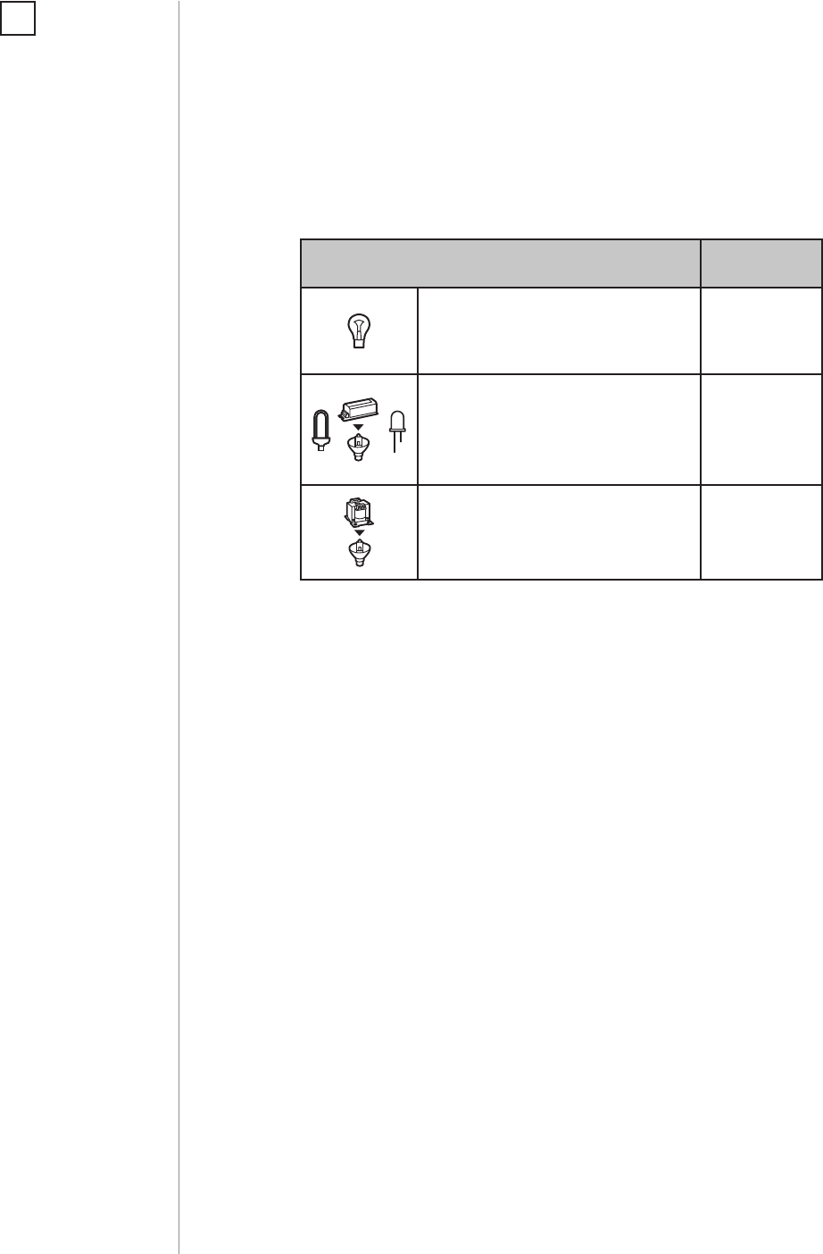
SUPPORTED LOADS
As a dimmer it operates under the following loads:
• 120V operated conventional incandescent and halogen light
sources
• 12V operated ELV halogen lamps and dimmable LED bulbs (with
electronic transformers)
• 12V operated MLV halogen lamps (with ferromagnetic
transformers)
• dimmable LED bulbs
• dimmable compact uorescent CFL tube lamps
• supported dimmable light sources (power factor > 0.5) with
minimal power of 5VA using FIBARO Bypass 2 (depending on the
type of load)
Without dimming function it may work with:
• compact uorescent CFL tube lamps with electronic ballast
• uorescent tube lamps with electronic ballast
• LED bulbs (power factor > 0.7)
• supported light sources (power factor > 0.5) with minimal power
of 5VA using FIBARO Bypass 2 (depending on the type of load)
#2: Supported loads
Applied load and the Dimmer 2 itself may be damaged if
the applied load is inconsistent with the technical speci-
cations!
When connecting FIBARO Dimmer 2 act in accordance with the
following rules:
• Do not connect loads greater or less than those recommended
• Do not connect dierent types of light sources simultaneously
• Do not connect the power supply without a load
• Do not connect more than one transformer with Dimmer 2 output
• When using magnetic transformer load it with 50% of its nominal
power at minimum
• Minimize number of electronic transformers in a circuit, noises
caused by them in electrical grids may aect Dimmer’s operation
!
CAUTION
FIBARO Dimmer 2
supports only com-
pact uorescent tube
lamps and uorescent
tube lamps with elec-
tronic ballast. Do not
connect other types
of uorescent lamps!
!
NOTE
You will nd more
about FIBARO Bypass
2 in chapter #3 on
page 7.
i
6
SUPPORTED LOADS
Supported load types 120VAC
Resistive loads
Conventional incandescent
and halogen light sources
25-125W
Resistive-capacitive loads
Fluorescent tube lamp (com-
pact / with electronic ballast),
electronic transformer, LED
25-100VA
Resistive-inductive loads
Ferromagnetic transformers 25-110VA
FIBARO Dimmer 2 uses dierent operating modes to control follow-
ing types of loads:
1. „Trailing edge” for resistive loads (R)
2. „Trailing edge” for resistive-capacitive loads (RC)
3. „Leading edge” for resistive-inductive loads (RL)
NOTE
Some types of the LED
bulbs and compact
uorescent lamps are
designed to work in
leading edge operat-
ing mode.
i
Recommended values of power for supported loads:
7
FIBARO BYPASS 2 FGB002
#3: FIBARO Bypass 2 (FGB-002)
FIBARO Bypass 2 (FGB-002) is a device designed to work with FIBARO
Dimmer 2 (FGD-212). It should be used in case of connecting LED
bulbs or energy saving compact uorescent lamps. FIBARO Bypass 2
prevents ickering of the LED lights and glowing of the turned o
compact uorescent lamps.
In the case of 2-wire connection, FIBARO Bypass 2 allows to reduce
minimum power of load required by the Dimmer 2 for correct
operation. FGB-002 provides powering of the Dimmer 2 in case
of controlling the low loads of minimum power down to 5VA (for
cosφ>0.5).
Device installation:
1. Switch o the mains voltage (disable the fuse)
2. Connect the Bypass 2 in accordance with „Installation” on page 8
3. Follow the Dimmer 2 installation
4. Force the calibration procedure with FIBARO Bypass 2 using
RED menu position (see „Operating the device” on page 12) or
through setting parameter 13 to 2 (see „Advanced parameters” on
page 22)
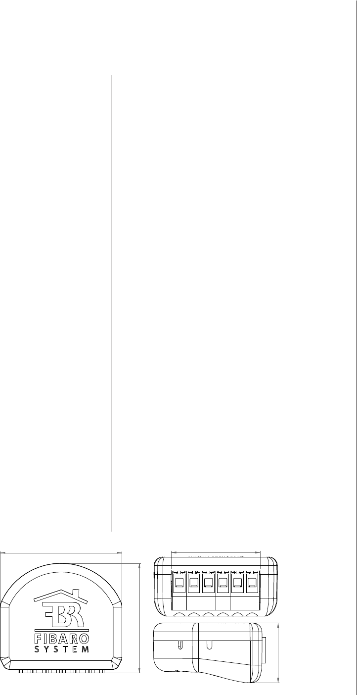
Power supply:
Operational temperature:
Dimensions (L x W x H):
Power consumption:
100-240VAC 50/60 Hz
32-95°F (0-35°C)
1.22 x 0.6 x 0.51 inch
(31 x 21,6 x 13 mm)
< 1.4 W
Specications:
CAUTION
In the case of 2-wire
connection do not
connect load below
minimal power with-
out FGB-002.
!
CAUTION
Dimmer 2 was de-
signed to work only
with FGB-002. Con-
necting other devices
may cause damage to
the Dimmer 2.
!
CAUTION
Bypass 2 works only
with Dimmer 2 in tra-
iling edge mode. Do
not connect the By-
pass to the Dimmer
operating in leading
edge mode.
!
CAUTION
Bypass 2 is sensitive
to the frequent chan-
ges of the state of
Dimmer 2 (alternate
switching on and off).
Significant changes in
brightness should not
be performed more
than once per second.
!

8
INSTALLATION
#4: Installation
Connecting the FIBARO Dimmer 2 in a manner inconsistent
with manual may cause risk to health, life or material
damage.
When connecting FIBARO Dimmer 2 act in accordance with the
following rules:
• Connect only in accordance with one of the diagrams
• Electrical installation must be protected by overcurrent protection
(fuse) of with a value not higher than 10A
• Dimmer 2 should be installed in a wall switch box compliant with a
relevant national safety standards and with depth no less than 2.4
inches (60 mm)
• Electrical switches used in installation should be compliant with the
relevant safety standards
• Length of wires used to connect the control switch should not
exceed 65 ft (20 m)
!
Installation of the FIBARO Dimmer 2:
1. Switch o the mains voltage (disable the fuse)
2. Open the wall switch box
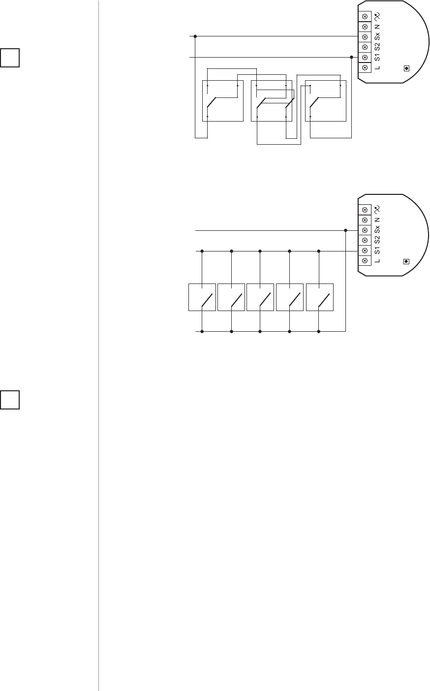
3. Connect with one of the following diagrams:
B
DIMMER
Notes for the diagrams:
L - terminal for live lead
S1 - terminal for switch no. 1 (has the option of
entering the device in learning mode)
S2 - terminal for switch no. 2
Sx - terminal for power supply to the switch con-
nected to the Dimmer 2
N - terminal for neutral lead
- output terminal of the Dimmer 2 (controlling
connected light source)
B - service button (used to add/remove the device
and navigate the menu)
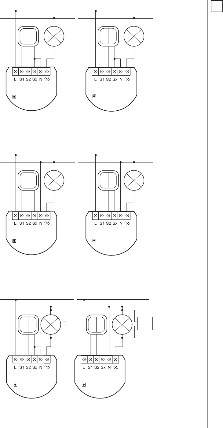
9
INSTALLATION
B
BYPASS
DIMMER
L
N
B
BYPASS
DIMMER
L
N
DIMMER DIMMER
L
N
BB
L
N
single switch double switch
Wiring diagram no. 2 - 3-wire connection
2-wire connection
Wiring diagram no. 3 - connecting FGB-002
3-wire connection
DIMMER DIMMER
L
N
BB
L
N
single switch double switch
Wiring diagram no. 1 - 2-wire connection
NOTE
Switch connected to
the S1 terminal is a
master switch. It acti-
vates the basic func-
tionality of the Dim-
mer 2 (turning the
light on/o, dimming)
and starts the learning
mode (Add/Remove).
The switch connected
to the S2 terminal is an
optional switch and
pushing it without
changing the congu-
ration parameters will
not aect the status of
the device. Function-
ality of the switches
can be reversed by
adjusting advanced
parameter (see „Ad-
vanced parameters”
on page 22).
i
10
INSTALLATION
4. After verifying correctness of connection switch on the mains
voltage
5. Wait around 30s for the calibration process to end (see „Calibra-
tion” on page 15), light may blink during the process
6. After successful calibration the device will be turned o by default
7. Add the device to the Z-Wave network (see „Adding/removing the
device” on page 11)
8. Turn o the mains voltage, then arrange the device and its anten-
na in a wall switch box
9. Close the wall switch box and turn on the mains voltage
B
DIMMER
Wiring diagram no. 5 - momentary wall switches
connection
NOTE
It is not recommend-
ed to install dierent
types of wall switches
(momentary, toggle,
etc.) in a 3-way con-
nection.
i
Wiring diagram no. 4 - 3-way switch connection
B
DIMMER
1 3
P
13
P2
1 3
P
Tips for arranging the antenna:
• Locate the antenna as far from metal elements as possible
(connecting wires, bracket rings, etc.) in order to prevent
interferences.
• Metal surfaces in the direct vicinity of the antenna (e.g. ush
mounted metal boxes, metal door frames) may impair signal
reception!
• Do not cut or shorten the antenna - its length is perfectly matched
to the band in which the system operates.
NOTE
After switching on the
mains voltage LED
indicator will signal
Z-Wave network in-
clusion state with a
colour:
GREEN - device added
RED - device not added
RED/GREEN ALTER-
NATELY- Z-Wave error
i

11
ADDING/REMOVING THE DEVICE
#5: Adding/removing the device
Adding (Inclusion) - Z-Wave device learning mode, allowing to add
the device to existing Z-Wave network.
To add the device to the Z-Wave network:
1. Place the Dimmer 2 within the direct range of your Z-Wave
controller
2. Identify switch no. 1 (turns the light on) or the B-button (located
on the device’s housing)
3. Set the main controller in (security/non-security) add mode (see
the controller’s manual)
4. Quickly, three times press switch no. 1 or the B-button
5. Wait for the adding process to end
6. Successful adding will be conrmed by the Z-Wave controller’s
message
NOTE
In case of problems
related to unknown
conguration or type
of external switch use
the B-button to add/
remove.
i
CAUTION
While adding the
Dimmer 2 to the
network with
connected toggle
switch, ensure that
all switch contact is
open (o). Otherwise
it will prevent adding/
removing the device
to/from the network.
!
Removing (Exclusion) - Z-Wave device learning mode, allowing to
remove the device from existing Z-Wave network.
To remove the device from the Z-Wave network:
1. Place the Dimmer 2 within the direct range of your Z-Wave
controller
2. Identify switch no. 1 (turns the light on) or the B-button (located
on the device’s housing)
3. Set the main controller in remove mode (see the controller’s
manual)
4. Quickly, three times press switch no. 1 or the B-button
5. Wait for the removing process to end
6. Successful removing will be conrmed by the Z-Wave controller’s
message
7. Dimmer 2 will start the calibration process (see „Calibration” on
page 15)
NOTE
Removing the Dimmer 2
from the Z-Wave net-
work restores all the
default parameters of
the device, but does
not reset power me-
tering data.
i
NOTE
For toggle switches in
default conguration
perform six position
changes.
i
NOTE
Adding in security
mode must be per-
formed up to 2 meters
from the controller.
i
NOTE
Adding/removing is
not possible during the
calibration procedure.
i
12
OPERATING THE DEVICE
#6: Operating the device
Controlling the Dimmer 2 using a switch:
Momentary switch (after releasing the switch a spring automatically
pushes back and disconnects the switch):
• Turning the light ON/OFF: change the position of switch no. 1. The
Dimmer 2 will be activated always at previously set brightness
level.
• Brightening/dimming the light: hold switch no. 1 down. When the
switch is held down, the Dimmer 2 will always reach the extreme
value of 1% or 99%.
• Turning the light ON completely: fast double-click switch no. 1.
The Dimmer 2 will set the load at 99%.
Toggle switch (operates as a two-position switch, it has no spring
that would set one position of the switch):
• Turning the light ON/OFF: toggle switch no. 1. The Dimmer 2 will
be activated always at previously set brightness level.
• Turning the light ON completely: toggle twice switch no. 1. The
Dimmer 2 will set the load at 99%.
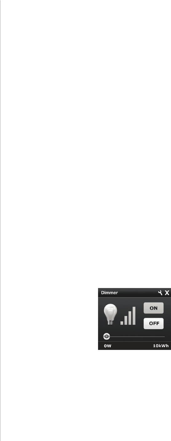
Controlling the Dimmer 2 using FIBARO Home Center controller:
After adding the Dimmer 2 to the network, it will be represented in
the FIBARO Home Center controller by the following icon:
Dimming/brightening is performed by moving the slider. The current
status of the Dimmer 2 is shown on the bar indicator.
Turning the device ON/OFF – ON and OFF icons are used for setting
the last saved state or turning o the Dimmer 2.

13
OPERATING THE DEVICE
Controlling the Dimmer 2 using a command: ALL ON/ALL OFF in
non-secure mode:
The Dimmer 2 responds to commands ALL ON/ALL OFF that may be
sent by the Z-Wave controller. ALL ON/ALL OFF commands are usually
implemented in the remote controllers using Z-wave protocol, and
they are used to issue commands directed to the entire system.
By default, both commands ALL ON and ALL OFF are accepted. Set-
tings may be changed by modifying the value of parameter 11 (see
„Advanced parameters” on page 22). In this way the user may de-
termine to which commands the device should respond.
Resetting the Dimmer 2:
1. Disconnect the power supply
2. Remove the Dimmer 2 from the wall switch box
3. Connect the power supply
4. Locate the B-button on the housing
5. Press and hold the B-button to enter the menu mode
6. Wait for the visual LED indicator to turn yellow
7. Quickly release and click the B-button again
8. After few seconds the device will be restarted, which is signalled
with the red LED indicator colour
9. The device enters the calibration mode
NOTE
Resetting the device is
not the recommend-
ed way of removing
the device from the
Z-Wave network. Use
reset procedure only
if the primary con-
troller is missing or
inoperable. Certain
device removal can be
achieved by the pro-
cedure of removing
described in „Adding/
removing the device”
on page 11.
i
Controlling the Dimmer 2 using the B-button:
FIBARO Dimmer 2 is equipped with a B-button, which allows to use
the MENU mode and additionally perform the following actions:
1x click:
• alarm mode cancellation (ashing alarm)
• exit the error mode
• select the desired MENU option (if MENU mode is active)
3x click:
• send the Node Info Z-Wave command frame (adding/removing)
Holding:
• enter the MENU mode (conrmed by the LED indicator)

14
OPERATING THE DEVICE
MENU mode & visual indications:
FIBARO Dimmer 2 has a MENU with each position indicated by the
specied LED indicator colour. In order to enter the menu press the
B-button and hold for at least 2 seconds. While the B-button is still
pressed, LED indicator colour will change in the following sequence:
BLUE - initiate the load calibration procedure (see „Calibration” on
page 15)
RED - load calibration procedure with FIBARO Bypass 2 (see „Calibra-
tion” on page 15)
WHITE - activate turning the load on/o using the B-button
GREEN - reset the energy consumption data memory (see „Power and
energy consumption measurement” on page 16)
VIOLET - initiate the Z-Wave network range test (see „Z-Wave range
test” on page 18)
YELLOW - reset the FIBARO Dimmer 2 to factory defaults
Release the B-button to choose the desired function and conrm your
choice with the B-button click.

15
CALIBRATION
#7: Calibration
Dimmer 2 is equipped with an algorithm of smart light source detec-
tion. Depending on the connected type of light source, it automat-
ically adjusts an optimal control mode (leading edge for inductive
loads, trailing edge for capacitive or resistive loads). The procedure of
learning the light source type is called calibration.
Calibration automatically adjusts maximum and minimum light levels
(parameter 1 and 2). However, the installer is obliged to verify the
proper operation of the device, according to control modes descrip-
tion. There is a 10% probability that calibration settings will require a
manual correction. In a 2-wire connection for loads other than resis-
tive parameter 1 settings must be adjusted manually.
Calibration procedure is performed always after removing the device
from the Z-Wave network. If the device is not included, after each
power on/o calibration will occur. For the included device, calibra-
tion is performed in accordance with the parameter 35 settings.
Calibration may be forced:
• by setting parameter 13 to 1 or 2 (with/without FIBARO Bypass 2)
• through triple clicking and holding the main light switch (each
hold for more than 5 seconds)
• by selecting the appropriate MENU option using the B-button
(see „Operating the device” on page 12).
By default, calibration is performed without FIBARO Bypass 2. In case
of connecting the Bypass 2, it is required to force the appropriate cal-
ibration procedure using B-button menu or through parameter 13.
The device saves the last calibration enforcement mode (with or with-
out Bypass 2).
The result of calibration will be conrmed with the LED indicator
glowing in one of the following colours:
GREEN - Light source recognized as dimmable, dimming levels set,
brightness may be controlled using the S1 switch.
YELLOW - Light source recognized as non-dimmable, possibility to
turn ON/OFF connected light with default parameters settings.
RED - Calibration procedure failed. Possible reasons: lack of connect-
ed load or connected light source exceeds maximum power, which
may be controlled by the Dimmer 2.
BLINKING RED - Calibration procedure failed. Possible reasons: in-
stallation failure or damaged load (causing activation of the overcur-
rent protection).
CAUTION
Some types of LED
and CF lamps are de-
signed to operate in
leading edge mode
(with conventional
dimmers). Information
about proper opera-
tion mode of the bulb
should be included in
its manual. In this case
you have to manually
force the desired op-
erating mode using
parameter 30.
!
CAUTION
After changing the
load launch the cali-
bration or remove and
add the device. Before
changing the operat-
ing mode or perform-
ing the calibration pro-
cedure the light must
be turned o. Verify
the operating mode,
according to product
documentation.
!
CAUTION
During the calibration
procedure, radio con-
nection is disabled and
the Dimmer 2 does not
respond to any com-
mands. It may cause
temporary problems
with communication
in the Z-Wave network.
After completing the
calibration, communi-
cation with the mod-
ule will be restored.
!

16
POWER AND ENERGY CONSUMPTION
#8: Power and energy
consumption
FIBARO Dimmer 2 allows for the active power and energy consump-
tion monitoring. Data is sent to the main Z-Wave controller, e.g. Home
Center. Measuring is carried out by the most advanced micro-control-
ler technology, assuring maximum accuracy and precision.
Electric active power - power that energy receiver is changing into a
work or a heat. The unit of active power is Watt [W].
Electric energy - energy consumed by a device through a time
period. Consumers of electricity in households are billed by sup-
pliers on the basis of active power used in given unit of time. Most
commonly measured in kilowatt-hour [kWh]. One kilowatt-hour is
equal to one kilowatt of power consumed over period of one hour,
1kWh = 1000Wh.
CAUTION
FIBARO Dimmer 2 in
the 3-wire connection
has the power and
energy measurement
function. In case of the
2-wire connection this
function is available
only for load of cosφ
≥ 0.99. In other cases
power is estimated
and can dier from ac-
tual power consumed
by the device.
!
CAUTION
FIBARO Dimmer 2
stores periodically
(every 5 minutes) the
consumption data
in the device mem-
ory. Disconnecting
the module from the
power supply will not
erase the energy con-
sumption data.
!
Resetting consumption memory:
Dimmer 2 allows to erase stored consumption data in three ways:
a) By resetting the device (see „Operating the device” on page 12).
b) Using functionality of a Z-Wave controller (see the controller’s man-
ual).
c) Manually clearing the data using the following procedure:
1. Make sure that the device is connected to the power supply
2. Press and hold the B-button for a few seconds, until LED indica-
tor glows GREEN
3. Release the B-button.
4. Press the B-button briey
5. Energy consumption memory has been erased
FGD-212
3-wire connection 2-wire connection
Bright-
ness>70%
Bright-
ness<70%
Bright-
ness>70%
Bright-
ness<70%
resistive load +/- (0.5 %
+ 0.2W)
+/- (2 %
+ 0.2W)
+/- (2 %
+ 0.2W)
+/- (4 %
+ 0.2W)
resistive-
inductive load
+/- (0.5 %
+ 0.2W)
+/- (2 %
+ 0.2W)
Power
metering
approximate*
Power
metering
approximate*
resisitve-
capacitive load
+/- (0.5 %
+ 0.2W)
+/- (2 %
+ 0.2W)
Power
metering
approximate*
Power
metering
approximate*
NOTE
Power measurement
in the 2-wire connec-
tion does not include
mains voltage uctu-
ations within +/- 10%.
i
Table of power measurement accuracy:
* Measurements in this
case are only illustra-
tive, returned values
may dier from the
actual measurement.
In the case of report-
ing incorrect values
change the values of
parameters 58 and 59.
17
ASSOCIATIONS
#9: Associations
The association enables the Dimmer 2 to control directly a device
included in Z-Wave network e.g. other Dimmer, Relay Switch, Roller
Shutter or scene (may be controlled only through a Z-Wave controller).
The Dimmer 2 provides the association of ve groups:
1st Association Group „Lifeline” reports state of the device. Main
Z-Wave+ network controller should be added to this group. The „Life-
line” group can handle only one device. It is not recommended to
modify this group.
2nd Association Group „On/O (S1)” is assigned to switch no. 1.
Sends BASIC command class frame according to the state of the de-
vice.
3rd Association Group „Dimmer (S1)” is assigned to switch no. 1.
Sends MULTILEVEL SWITCH command class frame. Allows sending
dim/brighten command to associated devices.
4th Association Group „On/O (S2)” is assigned to switch no. 2.
Sends BASIC command class frame according to the state of the de-
vice.
5th Association Group „Dimmer (S2)” is assigned to switch no. 2.
Sends MULTILEVEL SWITCH command class frame. Allows sending
dim/brighten command to associated devices.
To add an association (using the Home Center controller):
1. Go to device options by clicking the icon:
2. Select the „Advanced” tab
3. Specify to which group and what devices are to be associated
4. Wait for the conguration process to end. Sending relevant infor-
mation to devices added to associated groups may take even a
few minutes
NOTE
Dimmer 2 supports
the operation of mul-
tichannel devices.
Multichannel devices
are devices that in-
clude two or more cir-
cuits inside one physi-
cal unit.
i
NOTE
Association ensures
direct transfer of
control commands
between devices, is
performed without
participation of the
main controller and
requires associated
device to be in the di-
rect range.
i
Dimmer 2 in 2nd to 5th group allows for controlling 5 regular and 5
multichannel devices per an association group, out of which 1 eld is
reserved for the Z-Wave network main controller. It is not recommend-
ed to associate more than 10 devices in general, as the response time
to control commands depends on the number of associated devices.
In extreme cases, system response may be delayed.
Association (linking devices) - direct control of other devices within
the Z-Wave system network using the wall switch connected to the
Dimmer 2.

18
ZWAVE RANGE TEST
#10: Z-Wave range test
FIBARO Dimmer 2 has a built in Z-Wave network main controller’s
range tester.
Follow the below instructions to test the main controller’s range:
1. Press and hold the B-button until the visual indicator glows violet
2. Release the B-button
3. Press the B-button again, briey
4. Visual indicator will indicate the Z-Wave network’s range (range
signalling modes described below)
5. To exit Z-Wave range test, press the B-button briey
Z-Wave range tester signalling modes:
Visual indicator pulsing green - Dimmer 2 attempts to establish a
direct communication with the main controller. If a direct commu-
nication attempt fails, the device will try to establish a routed com-
munication, through other modules, which will be signalled by visual
indicator pulsing yellow.
Visual indicator glowing green - Dimmer 2 communicates with the
main controller directly.
Visual indicator pulsing yellow - Dimmer 2 tries to establish a rout-
ed communication with the main controller through other modules
(repeaters).
Visual indicator glowing yellow - Dimmer 2 communicates with
the main controller through the other modules. After 2 seconds the
device will retry to establish a direct communication with the main
controller, which will be signalled with visual indicator pulsing green.
Visual indicator pulsing violet - Dimmer 2 does communicate at the
maximum distance of the Z-Wave network. If connection proves suc-
cessful it will be conrmed with a yellow glow. It’s not recommended
to use the device at the range limit.
Visual indicator glowing red - Dimmer 2 is not able to connect to
the main controller directly or through another Z-Wave network de-
vice (repeater).
CAUTION
To make Z-Wave range
test possible, the de-
vice must be added
to the Z-Wave control-
ler. Testing may stress
the network, so it is
recommended to per-
form the test only in
special cases.
!
NOTE
Communication mode
of the Dimmer 2 may
switch between direct
and one using rout-
ing, especially if the
device is on the limit
of the direct range.
i

19
ERROR MODES
#11: Error modes
Description of error messages of the Dimmer 2
Events result from installation aws, faulty light source operation or
incorrect manual changes in advanced conguration. The device may
stop responding to user’s commands and actions, leaving the light
source o. Message with information about the type of error is sent
by default (using Z-Wave network).
Error messages:
A) OVERTEMPERATURE ERROR
Dimmer 2 features self-temperature measurement function. In case
of reaching critical temperature, the load is turned o and the gate-
way receives an information about exceeding maximum temperature
of the module.
B) LOAD ERROR
Dimmer 2 is equipped with functionality of detecting the burnt out
bulb. In case of such situation, Dimmer 2 sends the notication about
load failure. Described function is not available for values of parame-
ter 58 dierent than 0.
Power variation is detected in accordance with the settings of param-
eters 15 and 16.
Example:
Parameter 15 set to 30%.
Parameter 16 set to 5 seconds.
Dimmer 2 will detect the change of load at the moment of power
variation by 30% compared to standard power consumption (mea-
sured during the calibration) and after 5 seconds from brightness lev-
el stabilization.
This function is available only in a control mode compliant with the
mode recognized during the calibration (parameter 14 set to 1).
Appearing of an error may be the result of not connecting the load. It
may suggest burning out all of the loads connected to the Dimmer 2.
Damaged load should be immediately replaced. After connecting the
new load, FIBARO Dimmer 2 will return to normal operation.
C) SURGE ERROR
Appearing of an error may be the result of electrical surges, incorrect
load control (inductive load controlled in trailing edge mode) or con-
necting the prohibited type of load.
NOTE
Pressing any of the
connected switches or
changing state of the
device using the con-
troller will exit error
mode.
i
NOTE
If parameter 35 is set
to 3 or 4, the load will
be calibrated again af-
ter turning on the load
or an occurrence of
LOAD ERROR, SURGE
or OVERCURRENT er-
ror.
i

20
ERROR MODES
D) OVERCURRENT ERROR
Appearing of an error may also be the result of rapid powering on
the load. It may also occur if the soft-start functionality is disabled
(parameter 34 set to 0) or as a result of the short circuit.
If parameter 37 is set to 1, the device will automatically try to turn on
again.
If described error has been caused by the rapid powering on the load,
then FIBARO Dimmer 2 will return to normal operation after reen-
abling.
After three unsuccessful automatic tries of turning on the load, Dim-
mer 2 will stay in OVERCURRENT error mode (module turned o). In
such situation, it is required to remove the failure (possible short cir-
cuit in the installation.) Otherwise, it is recommended to set the long
soft-start (parameter 34 set to 2).
E) OVERLOAD ERROR
Appearing of an error is a result of connecting receivers with too
much power consumption. In this case FIBARO Dimmer 2 will auto-
matically turn o the lighting.
It is required to reduce power consumption of connected load (e.g. by
reducing the number of receivers) and turn on the light source again
by the wall switch or a Z-Wave command.
F) VOLTAGE DROP ERROR
Appearing of an error in a 2-wire connection may be the result of
mains voltage drop or a too high brightness level of the light source.
If parameter 37 is set to 1, the device will automatically try to turn on
again.
Voltage drop error suggests that parameter 2 value should be re-
duced until disappearing of the failure. You can also recalibrate the
load using parameter 13.
After three unsuccessful automatic tries of turning on the load, Dim-
mer 2 will stay in VOLTAGE DROP error mode (module turned o).
G) HARDWARE FAIL ERROR
Appearing of an error may be a result of serious hardware failure of
the Dimmer 2. In this case the Dimmer 2 sets the maximum brightness
level and the LED visual indicator starts blinking in red. All external
actions (Z-Wave commands, pressing the switches, menu settings)
will be ignored.
We recommend disconnecting the device from the power supply
and contacting the customer service or to initiate the guarantee
procedure.
This error may also appear as a result of enabling the Dimmer 2
without load connected to the output in 3-wire connection. It is not a
dangerous situation. We recommend disabling the fuse, connecting
the load and enabling the fuse again.

21
ADDITIONAL FUNCTIONALITY
#12: Additional functionality
Software update
Dimmer 2 features remote software update (initiated by the main
controller). Update status is signalled by the LED indicator with cyan
colour:
• slow blinking - transferring data via Z-Wave and saving to the
ash memory
• fast blinking - copying data from the external memory to the
memory of the microcontroller
Operating alarm data frames
FIBARO System allows user to set response of devices to alarm situa-
tions (response to data-frames ALARM_REPORT and SENSOR_ALARM_
REPORT). Dimmer 2 responds to the following types of alarms:
• General Purpose Alarm - GENERAL PURPOSE ALARM
• Smoke Alarm - ALARM CO2, ALARM CO, ALARM SMOKE
• Water Flooding Alarm - ALARM WATER
• Temperature Alarm - ALARM HEAT
Alarm data-frames are sent by devices that are system sensors (e.g.,
ood sensors, smoke detectors, motion detectors, etc.).
The device may respond in the following manner to received da-
ta-frames (settings are congured in conguration parameters, see
„Advanced parameters” on page 22):
0 - DEACTIVATION - the device does not respond to alarm data frames
1 - DIMMER 2 ON - the device turns on after detecting an alarm
2 - DIMMER 2 OFF - the device turns o after detecting an alarm
3 - ALARM FLASHING - the device periodically changes its status to
the opposite when it detects an alarm (lights on/o alternately)
22
ADVANCED PARAMETERS
#13: Advanced parameters
Dimmer 2 allows to customize its operation to user’s needs. The set-
tings are available in the FIBARO interface as simple options that may
be chosen by selecting the appropriate box.
In order to congure FIBARO Dimmer 2 (using the Home Center con-
troller):
1. Go to the device options by clicking the icon:
2. Select the „Advanced” tab
GROUP 0 - The Dimmer 2 behavior - Basic functionalities
1. Minimum brightness level (parameter is set automatically during
the calibration process)
The parameter can be changed manually after the calibration.
Available settings: 1-98 - percentage level of brightness
Default setting: 1Parameter size: 1 [byte]
2. Maximum brightness level (parameter is set automatically during
the calibration process)
The parameter can be changed manually after the calibration.
Available settings: 2-99 - percentage level of brightness
Default setting: 99 Parameter size: 1 [byte]
3. Incandescence level of dimmable compact uorescent lamps
Virtual value set as a percentage level between parameters MIN (1%)
and MAX. (99%). The Dimmer 2 will set to this value after rst switch
on. It is required for warming up and switching dimmable compact
uorescent lamps and certain types of light sources.
Available settings: 1-99 - percentage level of brightness
Default setting: 1Parameter size: 1 [byte]
4. Incandescence time of dimmable compact uorescent lamps
This parameter determines the time required for switching compact
uorescent lamps and certain types of light sources. Setting this pa-
rameter to 0 will disable the incandescence functionality.
Available settings: 0-255 (0-25.5s)
Default setting: 0Parameter size: 2 [bytes]
*
*
real scale
scale available
to the user
(virtual)
incandes-
cence level
of dimmable
compact uo-
rescent lamps
min
max
0% 1%
99%99%
CAUTION
The maximum
brightness level (pa-
rameter 2) must be
greater than the min-
imum brightness level
(parameter 1).
!
23
ADVANCED PARAMETERS
5. Automatic control - dimming step size
This parameter denes the percentage value of dimming step during
the automatic control.
Available settings: 1-99 - dimming step percentage value
Default setting: 1 Parameter size: 1 [byte]
6. Automatic control - time of a dimming step
This parameter denes the time of single dimming step set in param-
eter 5 during the automatic control.
Available settings: 0-255 (0-2.55s, in 10ms steps)
Default setting: 1 (10ms) Parameter size: 2 [bytes]
7. Manual control - dimming step size
This parameter denes the percentage value of dimming step during
the manual control.
Available settings: 1-99 - dimming step percentage value
Default setting: 1Parameter size: 1 [byte]
8. Manual control - time of a dimming step
This parameter denes the time of single dimming step set in param-
eter 7 during the manual control.
Available settings: 0-255 (0-2.55s, in 10ms steps)
Default setting: 5 (50ms) Parameter size: 2 [bytes]
9. State of the device after a power failure
The Dimmer 2 will return to the last state before power failure.
Available settings: 0 - the Dimmer 2 does not save the state before
a power failure, it returns to „o” position
1 - the Dimmer 2 restores its state before power
failure
Default setting: 1Parameter size: 1 [byte]
10. Timer functionality (auto - o)
This parameter allows to automatically switch o the device after
specied time from switching on the light source. It may be useful
when the Dimmer 2 is installed in the stairway.
Available settings: 0 - Function disabled
1-32767 - time to turn o measured in seconds
(1s-9.1h)
Default setting: 0Parameter size: 2 [bytes]
NOTE
Automatic control is
performed through:
- single push-button
click
- double push-button
click
- Z-Wave control fra-
mes
i
NOTE
Manual control is per-
formed through hol-
ding the push-button.
i
24
ADVANCED PARAMETERS
11. ALL ON/ALL OFF function
Parameter allows for activation/deactivation of Z-Wave commands
enabling/disabling all devices located in direct range of the main
controller.
Available settings: 0 - ALL ON not active, ALL OFF not active
1 - ALL ON not active, ALL OFF active
2 - ALL ON active, ALL OFF not active
255 - ALL ON active, ALL OFF active
Default setting: 255 Parameter size: 2 [bytes]
13. Force auto-calibration
Changing value of this parameter will force the calibration process.
During the calibration parameter is set to 1 or 2 and switched to 0
upon completion.
Available settings: 0 - readout
1 - force auto-calibration of the load without
FIBARO Bypass 2
2 - force auto-calibration of the load with
FIBARO Bypass 2
Default setting: 0Parameter size: 1 [byte]
14. Auto-calibration status (read-only parameter)
This parameter determines operating mode of the Dimmer 2 (auto-
matic/manual settings).
Available settings: 0 - calibration procedure not performed or Dim-
mer 2 operates on manual settings
1 - Dimmer 2 operates on auto-calibration settings
Default setting: 0Parameter size: 1 [byte]
15. Burnt out bulb detection
Function based on the sudden power variation of a specic value, in-
terpreted as a LOAD ERROR.
Available settings: 0 - function disabled
1-99 - percentage value of power variation,
compared to standard power consumption,
measured during the calibration procedure (to
be interpreted as load error/burnt out bulb)
Default setting: 30 Parameter size: 1 [byte]
16. Time delay of a burnt out bulb (parameter 15) or overload (pa-
rameter 39) detection
Time of delay (in seconds) for power variation detection, interpreted
as a LOAD ERROR or OVERLOAD detection (too much power connect-
ed to the Dimmer 2).
CAUTION
Parameter 15 is rele-
vant only when pa-
rameter 58 is set to 0
and the control mode
is consistent with the
mode set during the
calibration process
(parameter 30).
!
25
ADVANCED PARAMETERS
Available settings: 0 - detection of a burnt out bulb disabled
1-255 - delay time in seconds
Default setting: 5Parameter size: 2 [bytes]
19. Forced switch on brightness level
If the parameter is active, switching on the Dimmer 2 (S1 single click)
will always set this brightness level.
Available settings: 0 - function disabled
1-99 - percentage level of brightness
Default setting: 0Parameter size: 1 [byte]
GROUP 20 - Dimmer 2 operation - Switches
20. Switch type
Choose between momentary, toggle and roller blind switch.
Available settings: 0 - momentary switch
1 - toggle switch
2 - roller blind switch - two switches operate
the Dimmer 2 (S1 to brighten, S2 to dim)
Default setting: 0Parameter size: 1 [byte]
21. The value sent to associated devices on single click
This parameter denes the value sent to devices associated with Dim-
mer 2 after its enabling.
Available settings: 0 - 0xFF value is sent, which will set associated
devices to their last saved state
1 - current Dimmer 2 state is sent, which will
synchronize brightness level of associated de-
vices (other dimmers for example)
Default setting: 0Parameter size: 1 [byte]
22. Assign toggle switch status to the device status
By default each change of toggle switch position results in action of
Dimmer 2 (switch on/o) regardless the physical connection of con-
ntacts.
Available settings: 0 - device changes status on switch status
change
1 - device status is synchronized with switch
status
Default setting: 0Parameter size: 1 [byte]
26
ADVANCED PARAMETERS
23. Double click option - set the brightness level to MAX
Available settings: 0 - double click disabled
1 - double click enabled
Default setting: 1Parameter size: 1 [byte]
24. Command frames sent in 2nd and 3rd association groups (S1
associations)
Parameter determines, which actions will not result in sending frames
to association groups.
Available settings: 0 - all actions send to association groups
1 - do not send when switching ON (single click)
2 - do not send when switching OFF (single click)
4 - do not send when changing dimming level
(holding and releasing)
8 - do not send on double click
16 - send 0xFF value on double click
Default setting: 0Parameter size: 1 [byte]
25. Command frames sent in 4th and 5th association groups (S2
associations)
Parameter determines, which actions will not result in sending frames
to association groups.
Available settings: 0 - all actions send to association groups
1 - do not send when switching ON (single click)
2 - do not send when switching OFF (single click)
4 - do not send when changing dimming level
(holding and releasing)
8 - do not send on double click
16 - send 0xFF value on double click
Default setting: 0Parameter size: 1 [byte]
26. The function of 3-way switch
Switch no. 2 controls the Dimmer 2 additionally (in 3-way switch mode).
Function disabled for parameter 20 set to 2 (roller blind switch).
Available settings: 0 - 3-way switch function for S2 disabled
1 - 3-way switch function for S2 enabled
Default setting: 0Parameter size: 1 [byte]
27. Associations in Z-Wave network security mode
This parameter denes how commands are sent in specied asso-
ciation groups: as secure or non-secure. Parameter is active only in
Z-Wave network security mode. It does not apply to 1st Lifeline group.
NOTE
Parameter 25 values
may be combined,
e.g. 1+2=3 means
that associations on
switching ON or OFF
the Dimmer 2 (single
click) will not be sent.
i
NOTE
Parameter 24 values
may be combined,
e.g. 1+2=3 means
that associations on
switching ON or OFF
the Dimmer 2 (single
click) will not be sent.
i
27
ADVANCED PARAMETERS
Available settings: 0 - all groups (II-V) sent as non-secure
1 - 2nd group sent as secure
2 - 3rd group sent as secure
4 - 4th group sent as secure
8 - 5th group sent as secure
15 - all groups (II-V) sent as secure
Default setting: 15 Parameter size: 1 [byte]
28. Scene activation functionality
SCENE ID depends on the switch type congurations.
Available settings: 0 - functionality deactivated
1 - functionality activated
Default setting: 0Parameter size: 1 [byte]
SCENE ID value sent at specied conguration:
Momentary switches
SCENE ID: S1 input SCENE ID: S2 input
16 : 1 x click
14 : 2 x click
- : 3 x click
12 : hold
13 : release
26 : 1 x click
24 : 2 x click
25 : 3 x click
22 : hold
23 : release
Toggle switches
SCENE ID: S1 input SCENE ID: S2 input
10 : OFF to ON
11 : ON to OFF
14 : 2 x click
- : 3 x click
20 : OFF to ON
21 : ON to OFF
24 : 2 x click
25 : 3 x click
Roller blinds switches
SCENE ID: S1 input SCENE ID: S2 input
10 : turn ON (1 x click)
13 : release
14 : 2 x click
- : 3 x click
17 : brightening
11 : turn OFF (1 x click)
13 : release
14 : 2 x click
15 : 3 x click
18 : dimming
29. Switch functionality of S1 and S2
This parameter allows for switching the role of keys connected to S1
and S2 without changes in connection.
Available settings: 0 - standard mode
1 - S1 operates as S2, S2 operates as S1
Default setting: 0Parameter size: 1 [byte]
NOTE
Enabling scene activa-
tion functionality may
cause slight delay in
response to external
switches and sending
associations.
i
NOTE
Parameter 27 values
may be combined,
e.g. 1+2=3 means that
2nd & 3rd group are
sent as secure.
i
28
ADVANCED PARAMETERS
GROUP 30 - Dimmer 2 operation - Advanced functionality
30. Load control mode
This parameter allows to set the desired load control mode. The de-
vice automatically adjusts correct control mode, but the installer may
force its change using this parameter.
Forced auto-calibration will set this parameter’s value to 2.
Available settings: 0 - forced leading edge control
1 - forced trailing edge control
2 - control mode selected automatically (based
on auto-calibration)
Default setting: 2Parameter size: 1 [byte]
31. Load control mode recognized during auto-calibration
(read only)
Available settings: 0 - leading edge
1 - trailing edge
Default setting: —Parameter size: 1 [byte]
32. On/O mode
This mode is necessary while connecting non-dimmable light sourc-
es. Setting this parameter to 1 automatically ignores brightening/
dimming time settings. Forced auto-calibration will set this parame-
ter’s value to 2.
Available settings: 0 - on/o mode disabled (dimming is possible)
1 - on/o mode enabled (dimming is not pos-
sible)
2 - mode selected automatically
Default setting: 2Parameter size: 1 [byte]
33. Dimmability of the load (read only)
This parameter contains an information about possibility of dimming
the load detected during calibration procedure.
Available settings: 0 - Load recognized as dimmable
1 - Load recognized as non-dimmable
Default setting: —Parameter size: 1 [byte]
34. Soft-Start functionality
Time required to warm up the lament of halogen bulb.
Available settings: 0 - no soft-start
1 - short soft-start (0.1s)
2 - long soft-start (0.5s)
Default setting: 1Parameter size: 1 [byte]
CAUTION
Modications of pa-
rameters in GROUP 30
should be performed
only by a qualied in-
staller.
!
29
ADVANCED PARAMETERS
35. Auto-calibration after power on
This parameter determines the trigger of auto-calibration procedure,
e.g. power on, load error, etc.
Available settings: 0 - No auto-calibration of the load after power on
1 - Auto-calibration performed after rst power
on
2 - Auto-calibration performed after each power
on
3 - Auto-calibration performed after rst power
on or after each LOAD ERROR alarm (no load,
load failure, burnt out bulb), if parameter 37 is
set to 1 also after alarms: SURGE (Dimmer 2 out-
put overvoltage) and OVERCURRENT (Dimmer
2 output overcurrent)
4 - Auto-calibration performed after each pow-
er on or after each LOAD ERROR alarm (no load,
load failure, burnt out bulb), if parameter 37 is
set to 1 also after alarms: SURGE (Dimmer 2 out-
put overvoltage) and OVERCURRENT (Dimmer
2 output overcurrent)
Default setting: 1Parameter size: 1 [byte]
37. Behaviour of the Dimmer 2 after OVERCURRENT or SURGE
Occuring of errors related to surge or overcurrent results in turning
o the output to prevent possible malfunction. By default the device
performs three attempts to turn on the load (useful in case of mo-
mentary, short failures of the power supply).
Available settings: 0 - device permanently disabled until re-en-
abling by command or external switch
1 - three attempts to turn on the load
Default setting: 1Parameter size: 1 [byte]
39. Power limit - OVERLOAD
Reaching the dened value will result in turning o the load. Addi-
tional apparent power limit of 350VA is active by default.
Available settings: 0 - functionality disabled
1-350 - 1-350W
Default setting: 250 Parameter size: 2 [bytes]
NOTE
Parameter 39 is rele-
vant only when pa-
rameter 58 is set to 0.
i
30
ADVANCED PARAMETERS
NOTE
Alarm state may be
cancelled earlier, as
a result of pressing
the switch or sending
the Z-Wave command
frame.
i
GROUP 40 - Dimmer 2 operation - Alarms
40. Response to General Purpose Alarm
Available settings: 0 - No reaction
1 - Turn on the load
2 - Turn o the load
3 - Load blinking
Default setting: 3Parameter size: 1 [byte]
41. Response to Water Flooding Alarm
Available settings: 0 - No reaction
1 - Turn on the load
2 - Turn o the load
3 - Load blinking
Default setting: 2Parameter size: 1 [byte]
42. Response to Smoke, CO or CO2 Alarm
Available settings: 0 - No reaction
1 - Turn on the load
2 - Turn o the load
3 - Load blinking
Default setting: 3Parameter size: 1 [byte]
43. Response to Temperature Alarm
Available settings: 0 - No reaction
1 - Turn on the load
2 - Turn o the load
3 - Load blinking
Default setting: 1Parameter size: 1 [byte]
44. Time of alarm state
Available settings: 1-32767 (1-32767 seconds)
Default setting: 600 (600s) Parameter size: 2 [bytes]
Alarm settings - reports
45. OVERLOAD alarm report (load power consumption too high)
Available settings: 0 - No reaction
1 - Send an alarm frame
Default setting: 1Parameter size: 1 [byte]

31
ADVANCED PARAMETERS
46. LOAD ERROR alarm report (no load, load failure, burnt out bulb)
Available settings: 0 - No reaction
1 - Send an alarm frame
Default setting: 1Parameter size: 1 [byte]
47. OVERCURRENT alarm report (short circuit, burnt out bulb caus-
ing overcurrent)
Available settings: 0 - No reaction
1 - Send an alarm frame
Default setting: 1Parameter size: 1 [byte]
48. SURGE alarm report (Dimmer 2 output overvoltage)
Available settings: 0 - No reaction
1 - Send an alarm frame
Default setting: 1Parameter size: 1 [byte]
49. OVERHEAT (critical temperature) and VOLTAGE DROP (low volt-
age) alarm report
Available settings: 0 - No reaction
1 - Send an alarm frame
Default setting: 1Parameter size: 1 [byte]
GROUP 50 - Active power and energy reports
50. Active power reports
The parameter denes the power level change that will result in a new
power report being sent. The value is a percentage of the previous report.
Available settings: 0 - power reports disabled
1-100 (1-100%) - power report threshold
Default setting: 10 (10%) Parameter size: 1 [byte]
52. Periodic active power and energy reports
Parameter 52 denes a time period between consecutive reports.
Timer is reset and counted from zero after each report.
Available settings: 0 - periodic reports disabled
1-32767 (1-32767 seconds)
Default setting: 3600 (3600s) Parameter size: 2 [bytes]
32
ADVANCED PARAMETERS
53. Energy reports
Energy level change which will result in sending a new energy report.
Available settings: 0 - energy reports disabled
1-255 (0.01-2.55 kWh) - report triggering threshold
Default setting: 10 (0.1 kWh) Parameter size: 2 [bytes]
54. Self-measurement
The Dimmer 2 may include active power and energy consumed by
itself in reports sent to the main controller.
Available settings: 0 - Self-measurement inactive
1 - Self-measurement active
Default setting: 0Parameter size: 1 [byte]
58. Method of calculating the active power
This parameter denes how to calculate active power. It is useful in a
case of 2-wire connection with light sources other than resistive.
Available settings: 0 - measurement based on the standard algorithm
1 - approximation based on the calibration data
2 - approximation based on the control angle
Default setting: 0Parameter size: 1 [byte]
59. Approximated power at the maximum brightness level
This parameter determines the approximate value of the power that
will be reported by the device at its maximum brightness level.
Available settings: 0-500 (0-500W) - power consumed by the load
at the maximum brightness level.
Default setting: 0Parameter size: 2 [bytes]
NOTE
Parameter 58 is set
to 0 after forced au-
to-calibration.
i
NOTE
Parameter 59 works
only when parameter
58 has a value other
than 0.
i
33
SPECIFICATIONS
Power supply:
Power consumption:
Operational temperature:
Dimensions (L x W x H):
For installation in boxes:
Operational current:
Device temperature
protection:
Overcurrent protection:
Active element:
Device control:
Radio protocol:
Radio signal power:
Radio frequency:
Range:
Comply with EU directives:
120VAC 60 Hz
< 1.3W
32-95°F (0-35°C)
1.67 x 1.5 x 0.8 inch
(42.5 x 38.25 x 20.3 mm)
Ø ≥ 2 inches (Ø ≥ 50mm)
0.25-1.1A
221°F (105°C)
required external 10A circuit breaker,
all circuits wired as Class 1 or Electric
Light and Power circuit
semiconductor electronic switch ε
remotely - radio waves
directly - external switch
Z-Wave
up to 1mW
908.4, 908.42, 916 MHz US
up to 164 ft (50 m) outdoors
up to 98 ft (30 m) indoors
(depending on building materials)
RoHS 2011/65/EU
LVD 2006/95/EC
EMC 2004/108/EC
R&TTE 1999/5/EC
#14: Specications

34
LIMITED WARRANTY
This limited warranty is provided by Fibar USA, LLC (the “Company”), 1040 E. Lake Ave., Glenview, Illinois
60025, as the sole and exclusive remedy oered to a purchaser (the “Customer”) of the products (the “Prod-
ucts”) for any alleged defects in any of the Products. The warranty is subject to all terms sets forth below.
1. LIMITED WARRANTY:
Subject to the limitations of section 2, the company warrants that the products sold by the company to the
customer will be free from defects in material and workmanship under normal use and regular service and
maintenance for a period of one (1) year from the date of purchase of the products. The one-year period
may be referred to as the “limited warranty period”.
This is the sole and exclusive warranty given by the company with respect to the products and is in lieu of
and excludes all other warranties, express or implied, arising by operation of law or otherwise, including
without limitation, any implied warranties of merchantability, tness for a particular purpose, non-infringe-
ment and the implied condition of satisfactory quality.
The product is not, is not intended to function or be used as, should not be used as, and shall not be
deemed to be, an alarm system or home security system. The product’s intended use shall not include use
as an alarm system or home security system.
This limited warranty does not extend to any losses or damages due in whole or in part to misuse, accident,
abuse, neglect, normal wear and tear, negligence (other than the Company’s), unauthorized modication
or alteration, use beyond rated capacity, unsuitable power sources or environmental conditions, improp-
er installation, repair, handling, maintenance or application, third party actions or omissions (whether as
an agent or apparent agent of the Company), criminal acts, or any other cause not the direct fault of the
Company.
2. LIMITATION OF REMEDY:
If within the limited warranty period, the Customer discovers any covered warranty defects and noties the
Company within thirty (30) days of such discovery, pursuant to the Claims Procedure in Section 4 below,
the Company shall, at its option and as the Customer’s exclusive remedy, repair or replace F.O.B. point of
manufacture.
The remedies set forth in this limited warranty are exclusive. The sole and exclusive remedy for breach of
any warranty hereunder shall be limited to repair or replacement of the products.
In the event that the product cannot be repaired or replaced, the company reserves the right to substitute
a product of similar technical parameters.
The company will not refund the purchase price of the original product.
Failure by the Customer to give such written notice within the thirty (30) day time period shall be deemed
an absolute and unconditional waiver of the Customer’s claim for such covered defects. All costs and
expenses of dismantling, reinstallation and freight, including the time of the Company’s personnel and
representatives for site travel and diagnosis under this limited warranty, shall be borne by the Customer
unless accepted in writing by the Company. Products repaired or replaced during the limited warranty
period shall be covered by the foregoing limited warranty for the remainder of the limited warranty period.
The Customer assumes all other responsibility for any loss, damage, or injury to persons or property arising
out of, connected with, or resulting from the use of Products, either alone or in combination with other
products/components.
3. LIMITATION OF LIABILITY:
In no event, regardless of the form of the claim or cause of action (whether based in contract, infringement,
negligence, strict liability, other tort or otherwise), shall the company’s liability to the customer or any third
party exceed the price paid by the customer for the specic products giving rise to the claim or cause of
action.
To the maximum extent permitted by applicable law, the company shall not be liable to the customer or
any third party for any general, direct, indirect, incidental, special, consequential, or punitive damages, in-
cluding, but not limited to, loss of prots or anticipated prots, business interruption, loss of use, revenue,
reputation and data, costs incurred, loss or damage to property or equipment, bodily injury, or death, aris-
ing from any claim or cause of action relating to the product, whether such is based on warranty, contract,
tort (including negligence and strict liability.
These limitations shall apply notwithstanding any failure of essential purpose of any remedy. Some states
and/or jurisdictions do not allow the exclusion or limitation of incidental or consequential damages so the
above exclusions may not apply to certain customers.
The Customer assumes all other responsibility for any loss, damage, or injury to persons or property arising
out of, connected with, or resulting from the use of Products, either alone or in combination with other
products/components.
#15: Limited warranty

35
LIMITED WARRANTY
4. CLAIMS PROCEDURE:
The Customer shall make a claim by written notice to the Company through the contact information listed
on its website at www.baro.com or by contacting the Company through the telephone number listed on
the website. Any telephone conversations will be recorded. The Company will issue a designated claim
number for each claim made. The Customer may be contacted by an authorized warranty service represen-
tative to arrange a date for an inspection of the Product. This inspection shall be in the presence of the Cus-
tomer. The Product that is the subject of the claim shall be made available by the Customer together with
complete standard equipment and the documents conrming the Product’s purchase. Covered defects (as
determined by the Company or its authorized service representative) found during the limited warranty
period shall be remedied within thirty (30) days from the date of inspection or the date the Product is
delivered to the Company or its authorized service representative, whichever is later. The limited warranty
period shall be extended by the time that the Product is in the possession of the authorized service repre-
sentative or the Company.
Remember: before you submit a warranty claim, contact our technical support using telephone or e-mail.
More than 50% of operational problems is resolved remotely, saving time and money spent to initiating
claim procedure.
5. GOVERNING LAW AND BINDING ARBITRATION:
Please read this section carefully. It aects customers’ rights and will have a substantial impact on how
claims the company and the customer have against each other are resolved. This limited warranty contains
a binding arbitration provision which may be enforced by the parties.
The Company and the Customer agree that any claim or dispute at law or equity that has arisen or may
arise between them relating in any way to or arising out of this limited warranty or the Products will be
resolved in accordance with the provisions set forth in this Section.
A. Applicable Law. The Customer and the Company agree that, except to the extent inconsistent with
or preempted by federal law, the laws of the State of Illinois, without regard to principles of conict of
laws, will govern the limited warranty and Products and any claim or dispute that has arisen or may arise
between the Company and the Customer, except as otherwise stated herein. The Federal Arbitration Act
governs the interpretation and enforcement of this Section 5. The U.N. Convention on Contracts for the
International Sales of Goods shall not apply.
B. Agreement to Arbitrate. The Company and the Customer each agree that any and all disputes or
claims that have arisen or may arise between them relating to or arising out of this limited warranty or
the Products shall be resolved exclusively through nal and binding arbitration, rather than in a court
proceeding. Alternatively, the Customer may assert his/her claims in small claims court, if the claims qualify
and so long as the matter remains in such court and advances only on an individual (non-class, non-rep-
resentative) basis.
The Company and the Customer agree that each of them may bring claims against the other only on an
individual basis and not as a plainti or class member in any purported class or representative action or
proceeding. Unless both the Company and the Customer agree, the arbitration may not consolidate or join
more than one person’s claims and many not otherwise preside over any form of a consolidated, represen-
tative, or class proceeding.
C. Opt-Out. The Customer may opt-out of this agreement to arbitrate by sending the Company a writ-
ten opt-out notice, via certied mail and postmarked no later than 30 days after the date of purchase of
the Product. The opt-out notice must include the Customer’s name and address, the serial number of the
Product purchased, and the date and location of the purchase. All other parts of this limited warranty will
still apply.
D. Procedures. The arbitration shall be administered by JAMS pursuant to its Comprehensive Arbitration
Rules and Procedures or pursuant to JAMS’ Streamlined Arbitration Rules and Procedures, whichever as
applicable. JAMS’ rules are available at www.jamsadr.com. The use of the word “arbitrator” in this provision
shall not be construed to prohibit more than one arbitrator from presiding over the arbitration; rather, the
JAMS’ rules will govern the number of arbitrators that may preside over an arbitration. The Customer will
have a reasonable opportunity to participate in the selection of the arbitrator.
A Customer who intends to seek arbitration must rst make a written claim against the Company pursuant
to Section 4. If the Customer and the Company are unable to resolve the claim within thirty (30) days from
the date of the notice, the Company or the Customer may initiate arbitration proceedings. A form for ini-
tiating arbitration proceedings is available on JAMS’ website. In addition to ling the form with JAMS, the
party initiating the arbitration must mail a copy of the completed form to the other party. In the event the
Company initiates arbitration against a Customer, it will send a copy of the completed form to the physical
address the Company has on le for the Customer.
The arbitration hearing shall be held in the county in which the Customer resides or at another mutually
agreed location.
Arbitration uses a neutral arbitrator instead of a judge or jury. Discovery or the exchange of non-privileged
information will be allowed pursuant to JAMS’ rules. The arbitrator will decide the substance of all claims
in accordance with applicable law, including recognized principles of equity, and will honor all claims of
privilege recognized by law. An arbitrator can award the same damages and relief on an individual basis
that a court can award to an individual. The arbitrator’s award shall be nal and binding and judgment on
the award rendered by the arbitrator may be entered in any court having jurisdiction thereof. An award
will consist of a written statement stating the disposition of each claim, and will include a concise written
statement of the essential ndings and conclusions on which the award is based.

36
LIMITED WARRANTY
Payment of all ling, administration and arbitrator fees is governed by JAMS; provided, however, that when
a Customer initiates arbitration against the Company, the fee required to be paid by the Customer is that
amount designated by JAMS for consumer arbitrations. All other costs will be paid by the Company.
If an arbitrator or court decides that any part of this limited warranty is invalid or unenforceable, the other
parts of the limited warranty shall still apply to the extent applicable. In the event that this agreement to
arbitrate is wholly inapplicable, the Customers agree that any claim or dispute that has arisen or may arise
between the Customer and the Company must be resolved exclusively by a state or federal court located
in Cook County, Illinois. The Customer agrees to submit to the personal jurisdiction of the courts located
within Cook County, Illinois, for the purpose of litigating all such claims or disputes.
THE MANUFACTURER IS NOT RESPONSIBLE FOR ANY RADIO OR TV INTERFERENCE CAUSED BY UNAUTHO-
RIZED MODIFICATIONS TO THIS EQUIPMENT. SUCH MODIFICATIONS COULD VOID THE USER’S AUTHORITY
TO OPERATE THE EQUIPMENT.
This device complies with Part 15 of the FCC Rules.
Operation is subject to the following two conditions:
1. This device may not cause harmful interference
2. This device must accept any interference received, including interference that may cause undesired ope-
ration. This equipment has been tested and found to comply with the limits for a Class B digital device,
pursuant to part 15 of the FCC Rules. These limits are designed to provide reasonable protection against
harmful interference in a residential installation. This equipment generates, uses and can radiate radio
frequency energy and, if not installed and used in accordance with the instructions, may cause harmful
interference to radio communications. However, there is no guarantee that interference will not occur in a
particular installation. If this equipment does cause harmful interference to radio or television reception,
which can be determined by turning the equipment o and on, the user is encouraged to try to correct the
interference by one or more of the following measures:
• Reorient or relocate the receiving antenna.
• Increase the separation between the equipment and receiver.
• Connect the equipment into an outlet on a circuit dierent from that to which the receiver is connected.
• Consult the dealer or an experienced radio/TV technician for help.
Industry Canada (IC) Compliance Notice
This device complies with Industry Canada license-exempt RSSs. Operation is subject to the following two
conditions: (1) this device may not cause interference, and (2) this device must accept any interference,
including interference that may cause undesired operation of the device.
Cet appareil est conforme aux normes d’exemption de licence RSS d’Industry Canada. Son fonctionne-
ment est soumis aux deux conditions suivantes : (1) cet appareil ne doit pas causer d’interférence et (2)
cet appareil doit accepter toute interférence, notamment les interférences qui peuvent aecter son fonc-
tionnement.
Legal Notices
All information, including, but not limited to, information regarding the features, functionality, and/or
other product specication are subject to change without notice. Fibaro reserves all rights to revise or
update its products, software, or documentation without any obligation to notify any individual or entity.
Fibaro, Fibar Group logo, and Fibaro Dimmer 2 are trademarks of Fibar Group S.A. All other brands and
product names referred to herein are trademarks of their respective holders.
Disclaimer
The information contained herein is provided in connection with Fibaro products. No license, expressed or
implied by estoppel or otherwise, to any intellectual property rights is granted by this documents.
This documentation may contain references to third-party sources of information, hardware or software,
products or services (“collectively the “Third-Party Products or Services”). Fibaro does not control the Thir-
d-Party Products or Services and is not responsible for any Third-Party Products or Services.
Except as provided above or except to the extent prohibited by applicable law, Fibaro shall not be liable
for any incidental or consequential damages caused by the breach of any express or implied warranty.
Fibaro assumes no liability whatsoever, and Fibaro disclaims any express or implied warranty, relating to
the sale and/or use of the Fibaro products, including, but to limited to, liabilities and/or warranties relating
to tness for a particular purpose, merchantability, and/or infringement of any patent, copyright and/or
other intellectual property right.
Except to the extent prohibited by applicable law, Fibaro’s liability shall not exceed the price paid for the
Fibaro products from direct, indirect, special, incidental or consequential damages resulting from the sue
of the products, its accompanying software, or product specications, manuals, installation guides and/or
any other documentation.
Some states, provinces or jurisdictions do not allow the exclusion or limitation of incidental or consequen-
tial damages or other limitations on warranties, so the above limitations or exclusion may not apply to you.
You may also have other rights that vary from state to state or province to province.
The Device may be used with any certied Z-Wave product and should work with devices from other pro-
ducers. Each certied, Z-Wave compatible device, may be added to Fibaro System.
FIBARGROUP
FIBARO
www.baro.com