Fibar Group FGFS101Z5 Flood Sensor User Manual
Fibar Group S.A. Flood Sensor
UserManual.wiki
>
Fibar Group
>
FGFS101Z5 User Manual
User manual
Navigation menu
Upload a User Manual
Namespaces
Wiki Guide
HTML
PDF
Info
Views
User Manual
Discussion / Help
Navigation
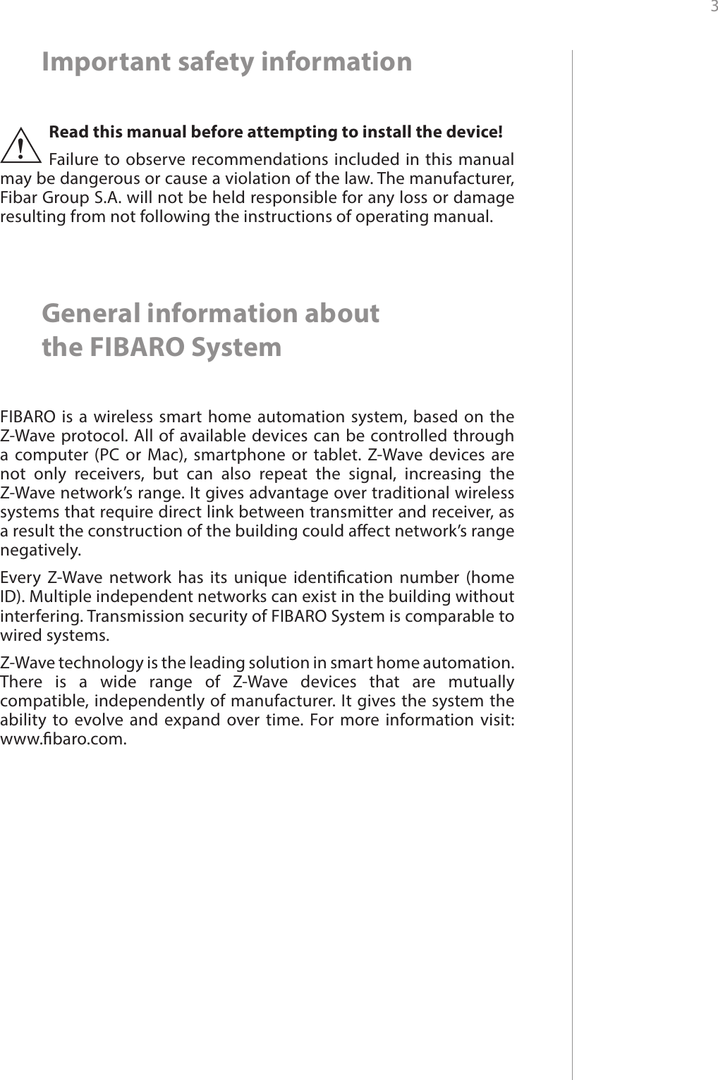
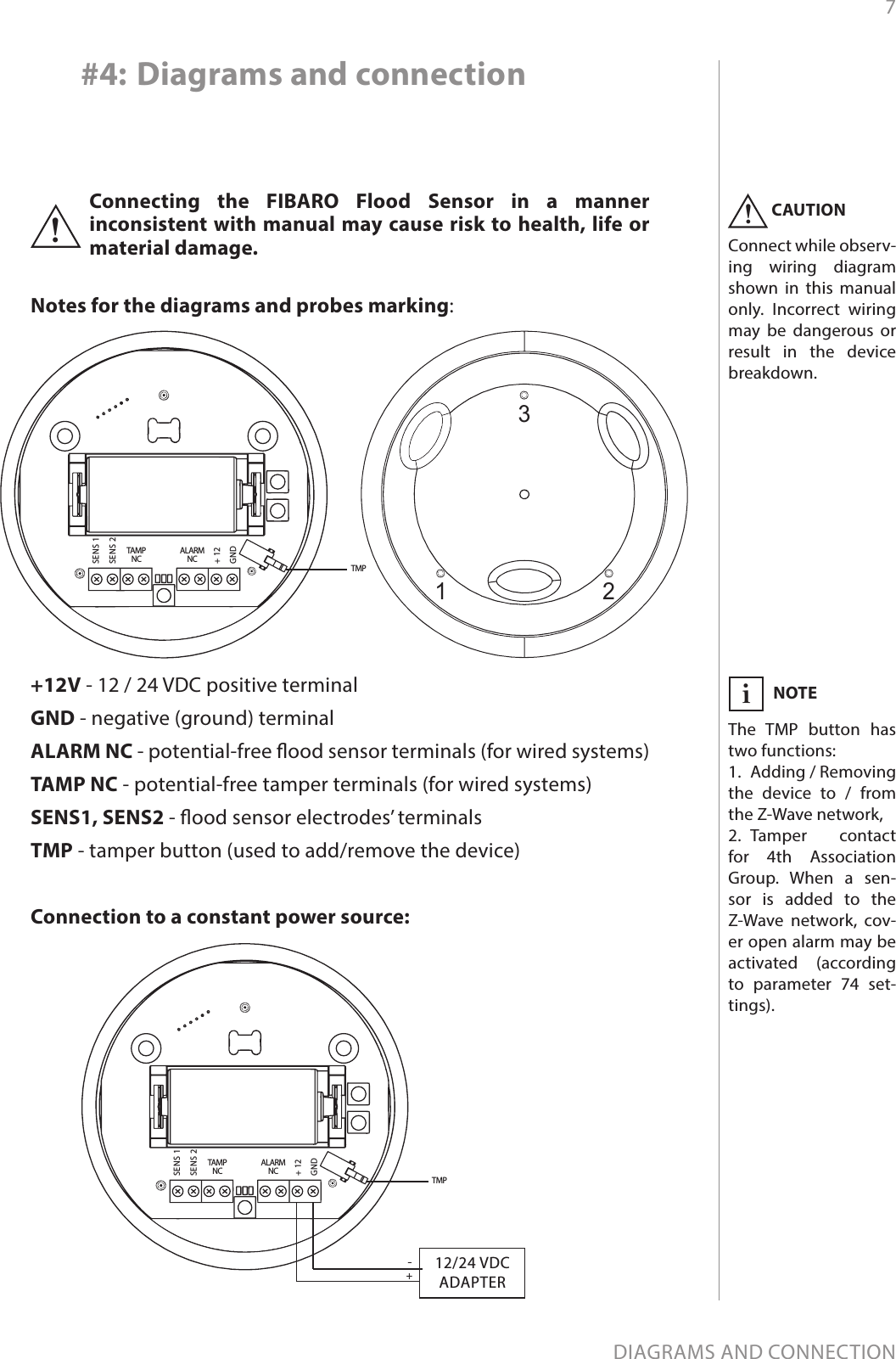
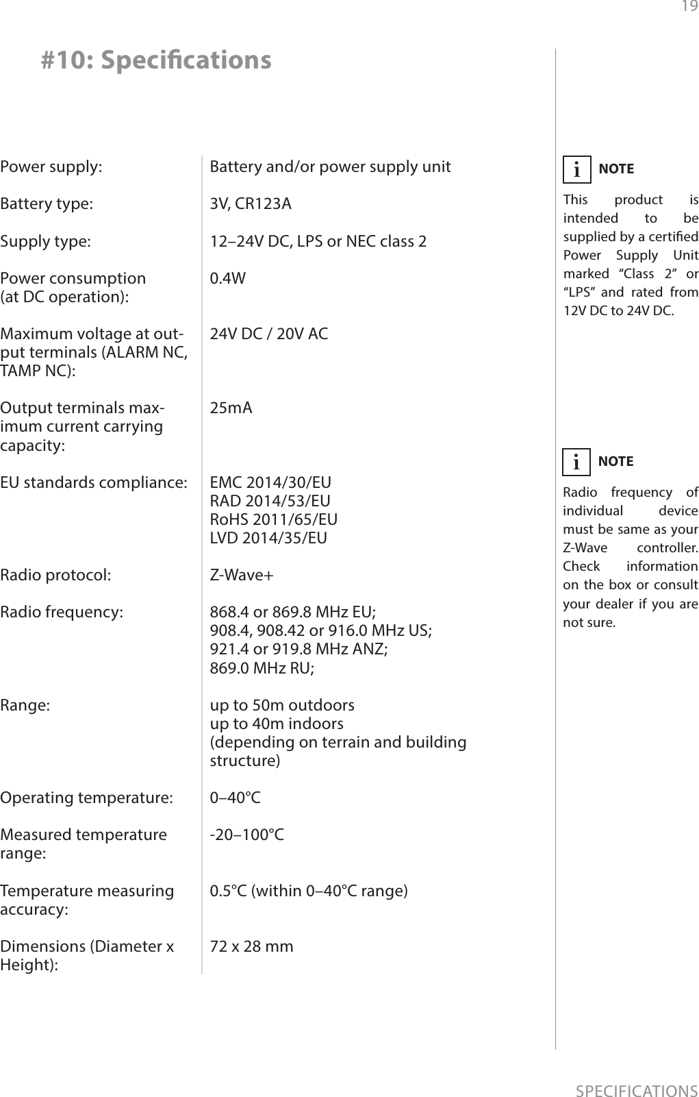
![14ADVANCED PARAMETERS#9: Advanced parameters1. Alarm cancellation delayDetermines time period (in seconds) by which a Flood Sensor will re-tain the ood state after the ooding itself has ceased. The sensor will keep on reporting ooding to the main controller. This parameter setting does not aect acoustic and visual alarms, which turn o im-mediately after ooding ceases.Available settings: 0-3600 (in seconds, each 1s)Default setting: 0Parameter size: 2 [bytes]2. Acoustic and visual signals On / O in case of oodingThe parameter allows for deactivation visual and acoustic alarm.Parameter allows for increasing a battery life. Setting changes will not aect the sensor’s communication with the main controller - com-mands to association groups, alarms and reports will still be sent.The Flood Sensor allows to customize its operation to user’s needs. The settings are available in the FIBARO interface as simple options that may be chosen by selecting the appropriate box.In order to congure the Flood Sensor (using the FIBARO Home Center controller):1. Go to the device options by clicking the icon: 2. Select the „Advanced” tab.Wake up interval (battery mode)Available settings: 0 or 60-86400 (in seconds, 1min - 24h)Default setting: 21 600 (every 6 hours)The Flood Sensor will wake up at each dened time interval and al-ways try to connect with the main controller. After successful com-munication attempt, the sensor will update conguration parame-ters, associations and settings and then will go into standby mode. After failed communication attempt (eg. no Z-Wave range) the device will go into standby mode and retry to establish connection with the main controller after the next time interval.Setting wake up interval to 0 disables sending Wake Up notication to the controller automatically. Wake up may be still performed man-ually by a single TMP button click.Longer time interval means less frequent communication and thus a longer battery life](https://usermanual.wiki/Fibar-Group/FGFS101Z5/User-Guide-3058108-Page-14.png)
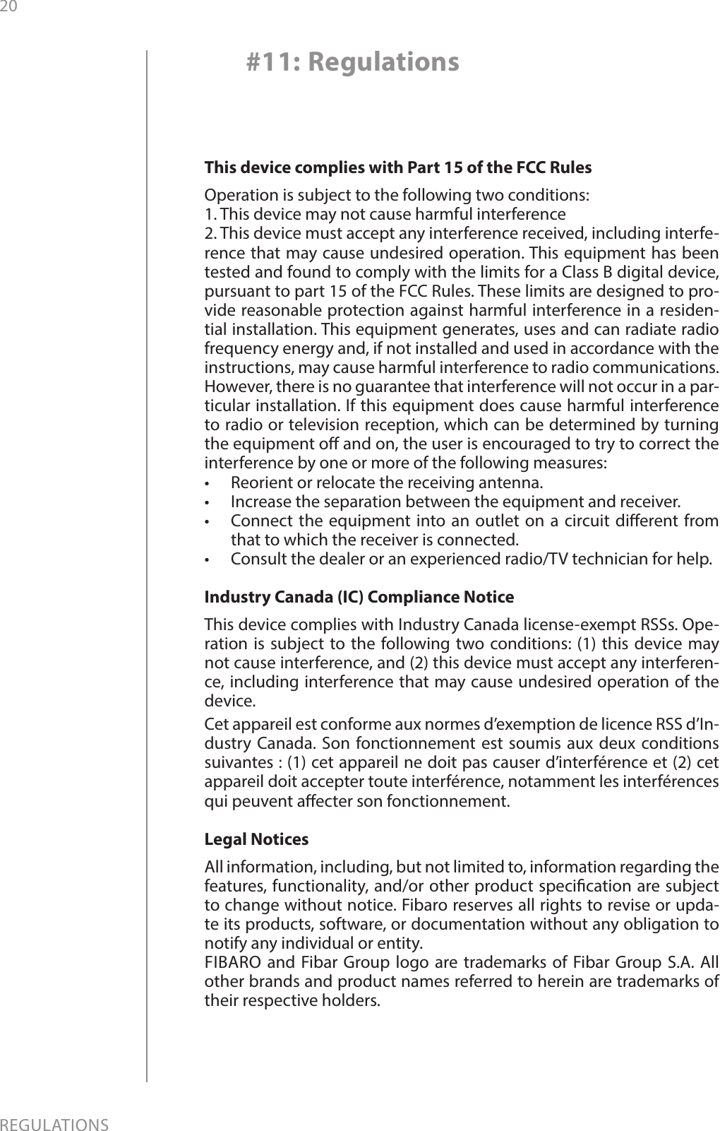
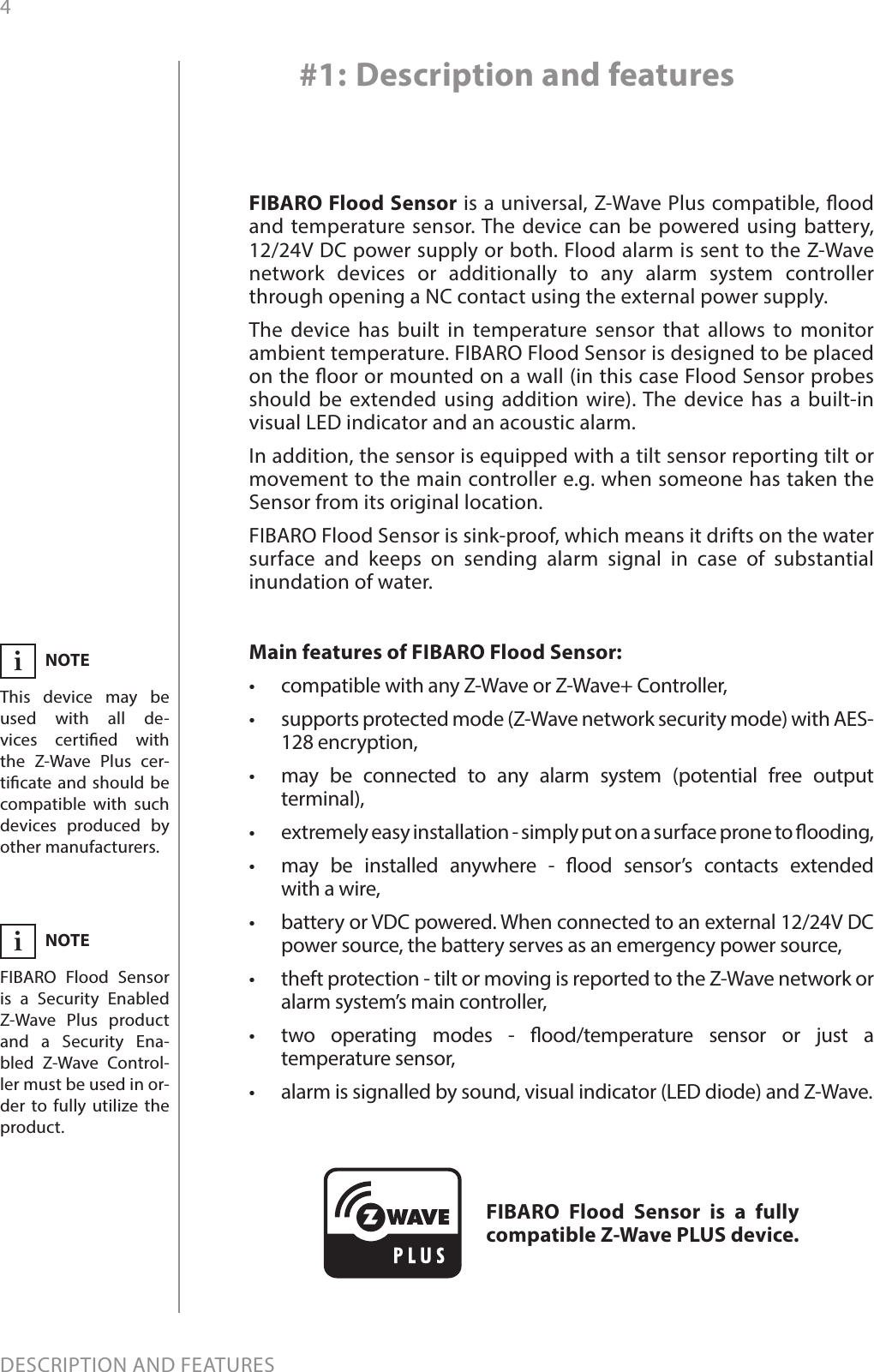
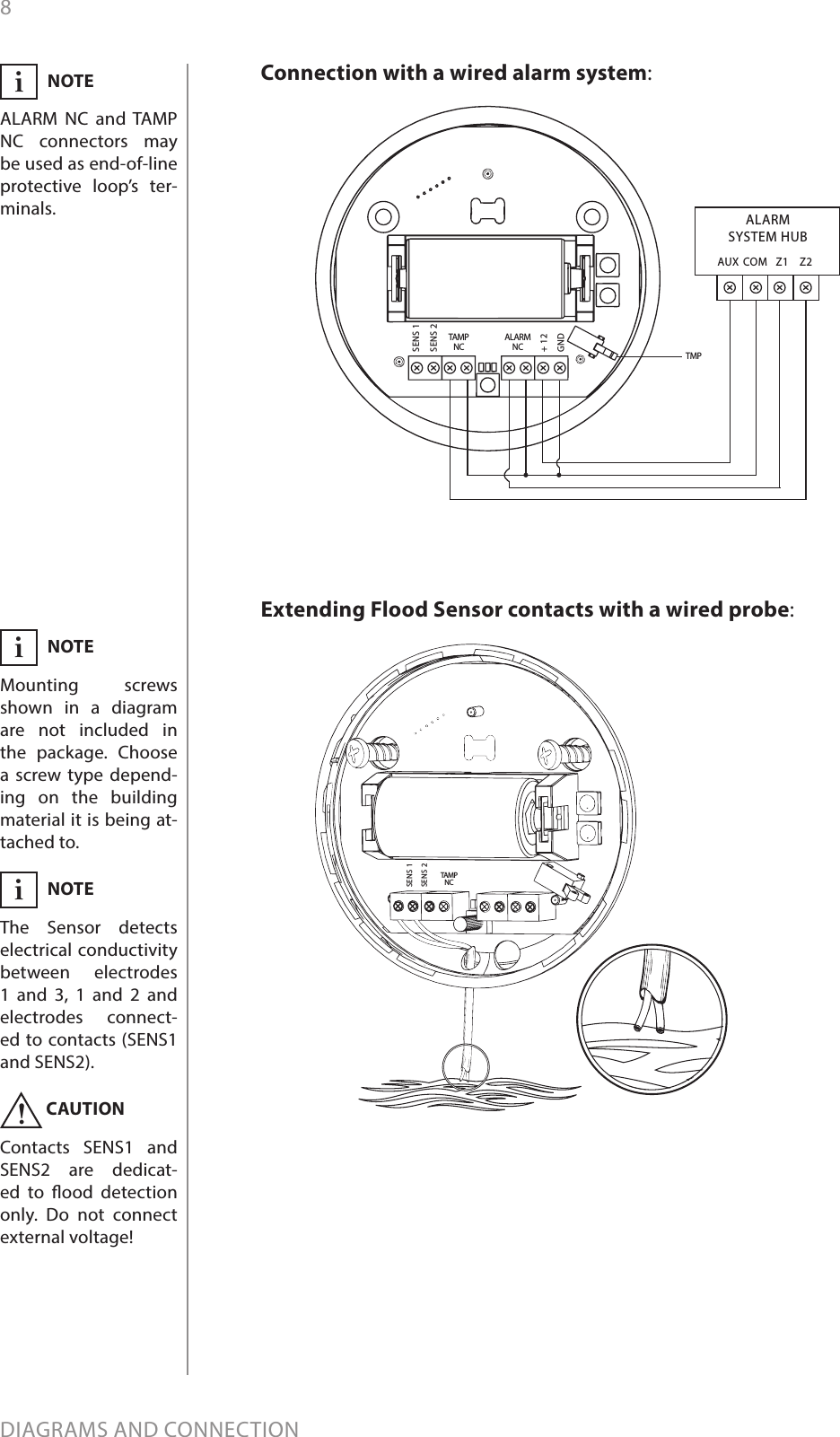
![15ADVANCED PARAMETERSAvailable settings: 0 - acoustic and visual alarms inactive1 - acoustic alarm inactive, visual alarm active2 - acoustic alarm active, visual alarm inactive3 - acoustic and visual alarms activeDefault setting: 3Parameter size: 1 [byte]7. Requested dimming level / roller blind opening level when send-ing turn on / open command to 2nd association group devicesDetermines the requested “on” level to be sent to devices from 2nd association group upon ood event.Available settings: 1-99 - requested level255 - turn a device onDefault setting: 255 Parameter size: 2 [bytes]9. Deactivate turning o devices in 2nd association group & alarm cancellation in 3rd groupThis setting decides whether device turn o commands and alarm cancellation notications will be sent to devices in 2nd and 3rd asso-ciation groups (respectively)Setting the parameter’s value to 0 disables sending these two com-mands to associated devices. This means that these devices WILL NOT be informed when the ooding has ceased. It is still possible to cancel alarms in 3rd association group by choosing second (green) menu position (see “Menu & visual indications” on page 10).Available settings: 0 - alarm (ooding) cancellation inactive1 - alarm (ooding) cancellation activeDefault setting: 1Parameter size: 1 [byte]10. Temperature measurement intervalTime interval (in seconds) between consecutive measurements of battery level and temperature (done by built-in temperature sensor).If the temperature diers from previously reported by a value deter-mined in parameter 12, it will be reported to the Z-Wave controller. In battery mode more signicant battery level changes will be report-ed. Short time intervals mean more frequent communication, which results in shortened battery life.After consecutive FAILED and SUCCESSFUL communication attempts, the Sensor will go to standby mode.Available settings: 1-65535 (in seconds)Default setting: 300 (5min) Parameter size: 4 [bytes]12. Temperature measurement hysteresisDetermines a minimum temperature change value (insensitivity lev-el), resulting in a temperature report being sent to the main control-](https://usermanual.wiki/Fibar-Group/FGFS101Z5/User-Guide-3058108-Page-15.png)
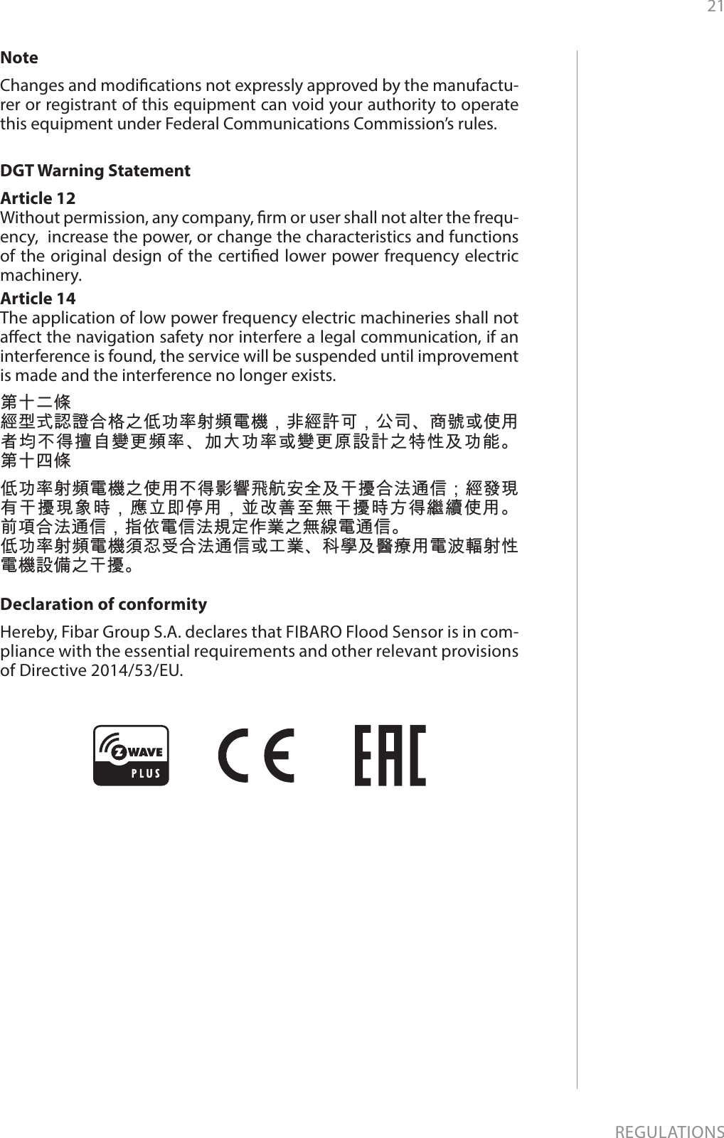
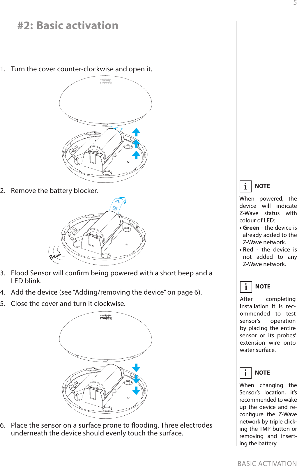
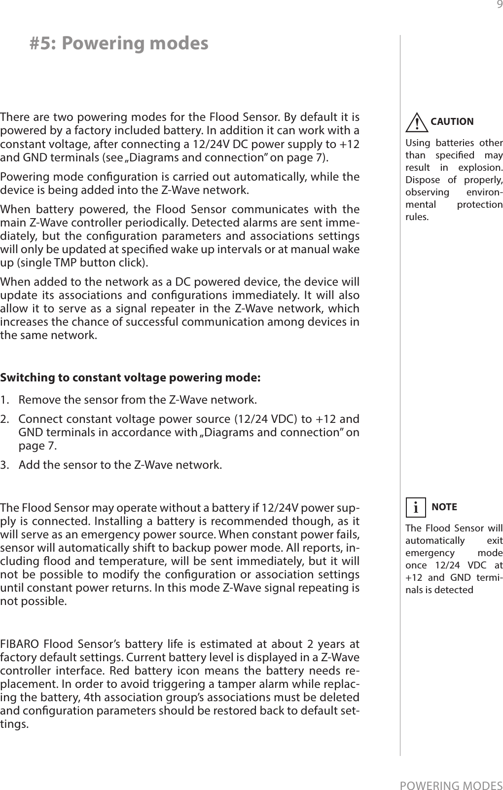
![16ADVANCED PARAMETERSler, according to the parameter 10 settings.Available settings: 1-1000 (each 0.01°C)Default setting: 50 (0.5°C) Parameter size: 2 [bytes]50. Low temperature alarm thresholdThe parameter stores a temperature value, below which visual indi-cator blinks with a colour determined by a parameter 61 settings. By default the visual indicator blinks blue.Available settings: - 10000 to +10000 (each 0.01°C)Default setting: 1500 (15°C) Parameter size: 2 [bytes]51. High temperature alarm thresholdThe parameter stores a temperature value, above which visual indica-tor blinks with a colour determined by the parameter 62 settings. By default the visual indicator blinks red.Available settings: - 10000 to +10000 (each 0.01°C)Default setting: 3500 (35°C) Parameter size: 2 [bytes]61. Low temperature alarm indicator colourParameter stores RGB colour value (see the note below for details).Available settings: 0-16777215Default setting: 255 Parameter size: 4 [bytes]62. High temperature alarm indicator colourParameter stores RGB colour value (see the note below for details).Available settings: 0-16777215Default setting: 16711680 Parameter size: 4 [bytes]iNOTEThe main controller interprets colours as a sum of its component col-ours value. Each colours value is a number from 0 to 255.Indicated colour = 65536 * RED + 256 * GREEN + BLUEColour Decimal valueRed 16711680Green 65280Blue 255Yellow 16776960Turquoise 65535Orange 16750848White 16777215Indicator turned o 0](https://usermanual.wiki/Fibar-Group/FGFS101Z5/User-Guide-3058108-Page-16.png)
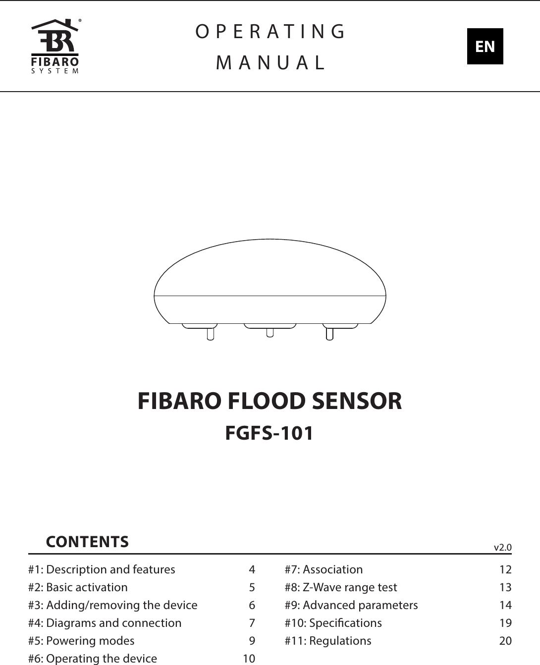
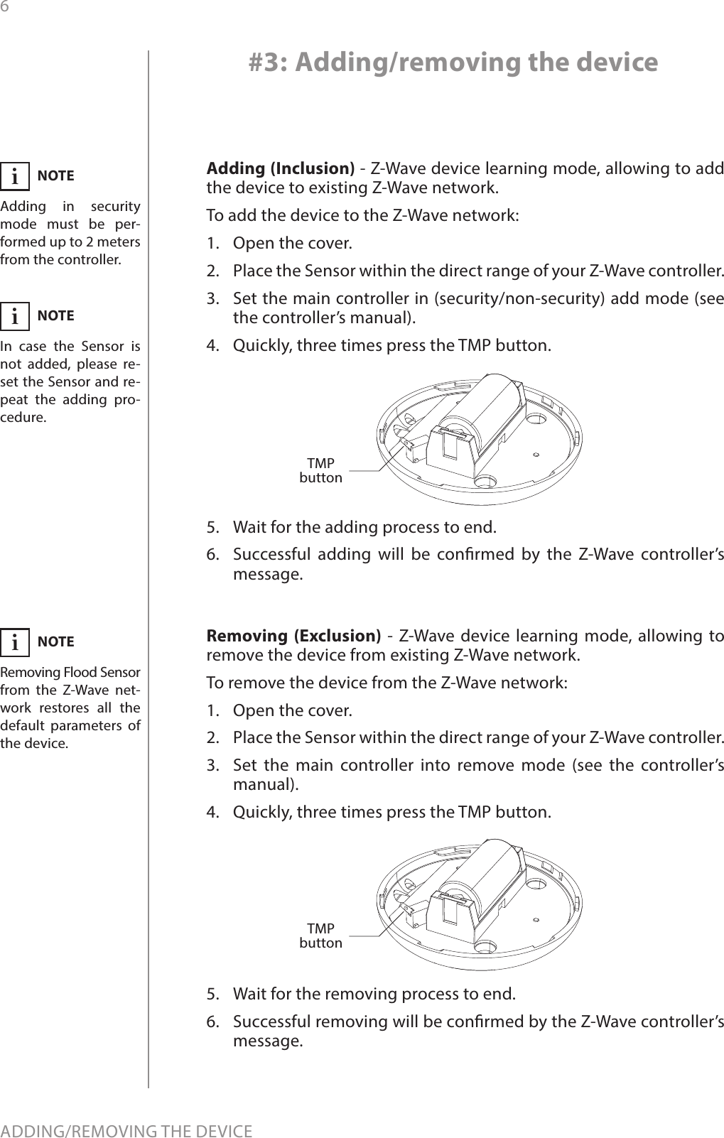
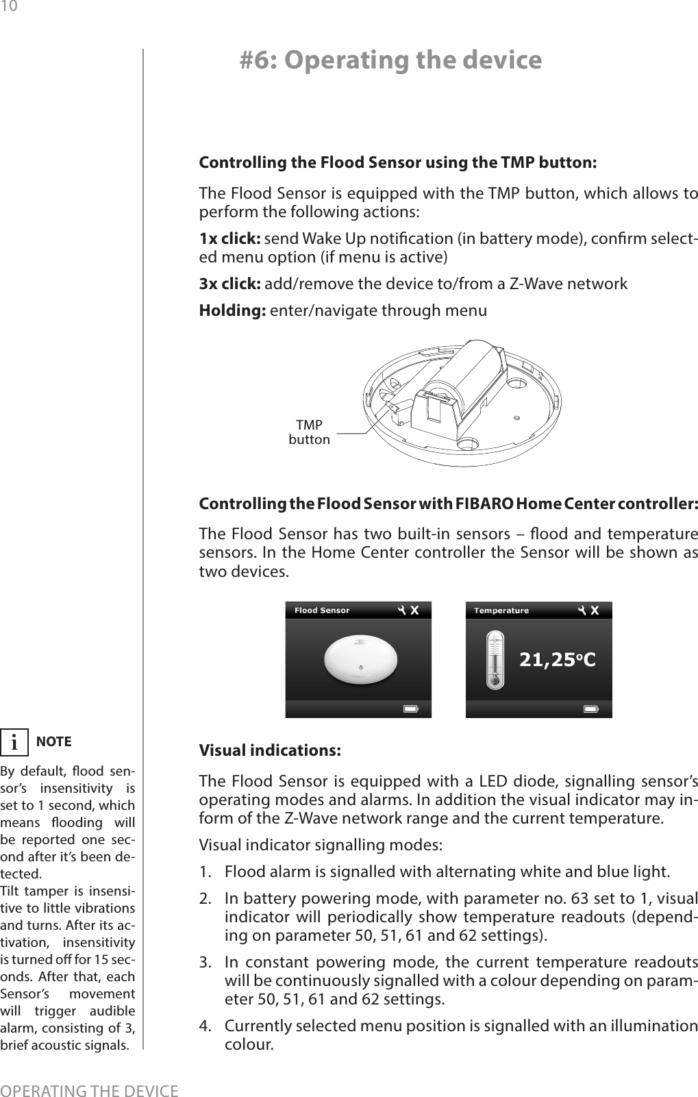
![17ADVANCED PARAMETERS63. Temperature indication using LED visual indicatorParameter determines visual indicator’s operation. Setting to 0 turns the temperature LED indication o, saving battery life.Available settings: 0 - visual indicator does not indicate the temperature1 - visual indicator indicates the temperature (blink) every Temperature Measurement Inter-val (parameter 10, constant current and bat-tery) and Wake Up Interval (battery mode)2 - visual indicator indicates the temperature continuously, only in constant power modeDefault setting: 2Parameter size: 1 [byte]73. Temperature measurement compensationParameter stores a temperature value to be added to or deducted from the current temperature measured by internal temperature sen-sor in order to compensate the dierence between air temperature and temperature at the oor level.Available settings: -10 000 to +10 000Default setting: 0 (0.00°C) Parameter size: 2 [bytes]74. Alarm frame sent to 1st and 4th Association Group activation (MOVEMENT_TAMPER / BUTTON_TAMPER)The device is able to report tamper alarms resulting from sensor’s tilt/movement or TMP button state change (e.g. taking o the top cover).Available settings: 0 - tamper alarms inactive1 - button tamper alarm active2 - movement tamper alarm active3 - button and movement tampers alarm activeDefault setting: 2Parameter size: 1 [byte]75. Alarms signalization durationThe device is capable of automatically turning o alarm signalization after a certain amount of time. Long lasting alarm may reduce battery life, when constantly signalized. The parameter determines time after which alarm will become “quiet” - still active but the device will go into battery saving mode. Visual or acoustic alarm will be reactivated after time specied in the parameter 76. When alarm status ceases, alarm will be turned o immediately.Available settings: 0 - alarms active indenitely1-65535 - time in secondsDefault setting: 0Parameter size: 4 [bytes]NOTEParameter 75 is ig-nored when parame-ter 2 is set to 0.i](https://usermanual.wiki/Fibar-Group/FGFS101Z5/User-Guide-3058108-Page-17.png)
![18ADVANCED PARAMETERS76. Alarm signalization reactivation periodParameter determines a time period after which an alarm will be turned back on (in case it was turned o by parameter 75 setting). It will also resend commands to 2nd and 3rd association groups as if the alarm was detected again.Available settings: 0 - alarm reactivation inactive1-65535 - time in secondsDefault setting: 0Parameter size: 4 [bytes]77. Flood sensor functionality turned oAllows to turn o the internal ood sensor. Tamper and built in tem-perature sensor will remain active.Available settings: 0 - Default ood sensor operation (ood detec-tion, reactions)1 - Built-in ood sensor TURNED OFF (does not change its state in the main controller, does not send alarm notications nor turn on/o commands to 2nd/3rd association groups with ood state changes. Always visible in the main controller as turned o)Default setting: 0Parameter size: 1 [byte]78. Associations in Z-Wave network security modeThis parameter denes how commands are sent in specied associa-tion groups: as secure or non-secure. Parameter is active only in Z-Wave network security mode. It does not apply to 1st “Lifeline “group.Available settings: 0 - none of the groups sent as secure1 - 2nd group ”Control” sent as secure2 - 3rd group ”Alarm” sent as secure4 - 4th group „Tamper” sent as secureDefault setting: 7Parameter size: 1 [byte]NOTEIn case a time period set in parameter 76 is shorter than the one specied in parameter 75, the device will not quiet the alarm, it will remain active.i](https://usermanual.wiki/Fibar-Group/FGFS101Z5/User-Guide-3058108-Page-18.png)