Fiber Span AC-3101-BTR Non-Broadcast FM Transmitter/Repeater User Manual A1471 in Word
Fiber-Span LLC Non-Broadcast FM Transmitter/Repeater A1471 in Word
users manual

A1471 User Manual
Fiber-Span
Installation Guide and User Manual
AC3101-BTR-4
Fiber Optic Transmission System
1U, 19” Subrack Enclosure
AC3101-BTR-RM
Fiber Optic Transmission System
NEMA Type 4X Enclosure
Fiber-Span
One Possumtown Road
Piscataway, NJ 08854
732.564.9000
732.564.1990 Fax
www.fiber-span.com

A1471 User Manual
Introduction
This high performance Analog RF Fiber Optic Transmission System converts RF
signals into intensity modulated light to be carried through standard single mode
optical fiber to the Optical Receiver. The Receiver converts the modulated light
back to the original RF signal. Fiber-Span uses high performance optical
components to ensure maximum dynamic range.
1 Warnings
Warning: Invisible radiation exits from areas labeled “Aperture”
A US standard 120V AC 60 Hz to 12VDC power supply powers the units. Use
precautions to prevent electrical shock hazards. Always terminate the RF
connections before applying power to the unit.
2 Product overview
The optical transmission system is comprised of one AC3101-BTR-4 base subrack
with four AC300T and four AC300R modules internally installed and front panel
LED power indicator, and four AC3101-BTR-RM remote Nema Type 4X
enclosures. Each AC3101-BTR-RM contains one AC106 fiber optic transceiver,
one FS-LNA1 low noise amplifier, one FS-PA1 power amplifier, one band pass
filter, one low pass filter, and one removable 3dB RF attenuator. In addition, both
the subrack and remote units are supplied with an external power supply and
locking cable, which is interchangeable between units of all types.
3 Installation
This transmission system is designed to be setup by professional
communications systems installers. System installers should be from, a
public utility, Nuclear Power Plant, or other qualified personnel.
The AC3101-BTR-4 subrack is compatible with a standard 19” 1U rack, and
mounts on the rack system using standard hardware and practices. AC3101-BTR-
RM remote units should be mounted securely using the four enclosure mounting
holes provided. AC3101-BTR-RM units should be mounted flat against a wall or
column with the long dimension perpendicular to the floor, hinge on the left,
A1471 User Manual
enclosure latch on right, and vent at top. Provide adequate airflow to the lower right
and top vents. Connect RF and Optical cables before powering up the modules.
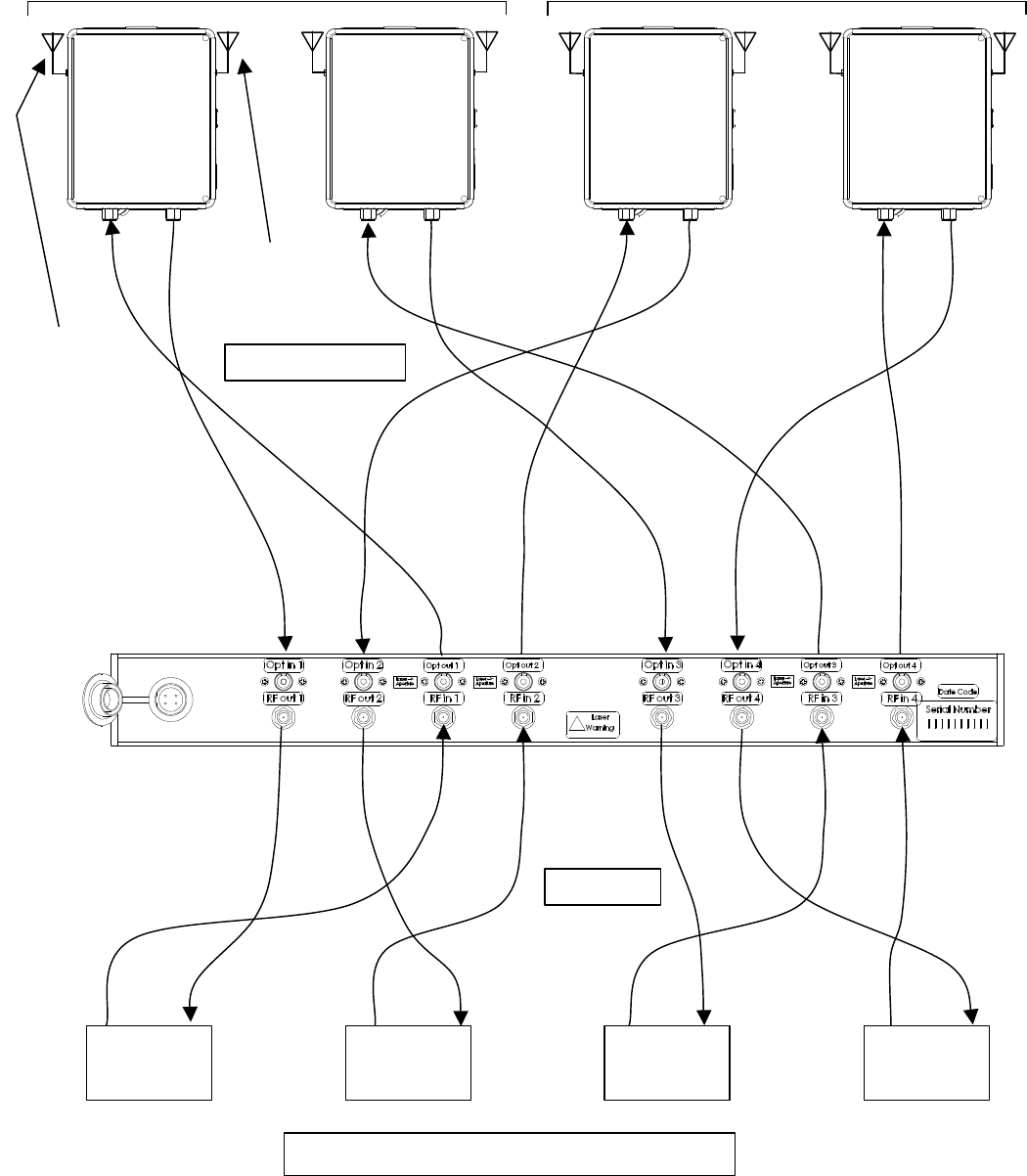
Connect fiber optic and RF cables as shown below:
A2-4a
BTR-700 C6-4a
BTR-700 C6-8a
BTR-700
A2-7b
BTR-700
Facility 1 Facility 2
C6-4a
A2-4a C6-8a
A2-7b C6-4a
A2-4a C6-8a
A2-7b
Remote 1
Remote 3
Remote 2
Remote 4
Opt in Opt in Opt in Opt in
Opt out Opt out Opt out Opt out
Example of Channel
Assignments:
A2-4a = A2 Band, Group 4a
Fiber Optic Cables
RF Cables
CLA-1
Antenna
(Blue) Typical
CLA-3
Antenna
(Red) Typical
System Connection Diagram
A1471 User Manual
Setup Program BTR-700 Radios and Beltpacks to frequency groups as
indicated in System Connection Diagram. See appendix for BTR frequency charts
for reference. Set the transmitter RF output power for 100 mW. Be sure to
terminate the transmitter RF output before power up.
To install fiber optic cable to subrack, remove dust covers, clean optical
connector, align FC/APC connector key and hand tighten. Do not overtighten.
To install fiber optic cable to remote units, see attached fiber installation guide.
This guide is also provided on the inside lid label of remote units. Clean optical
connectors prior to installation.
To power up subrack and remote units, unsnap dust cover from power supply
receptacle and insert the provided power supply plug into the receptacle on the
unit. Align plug key, and push plug into receptacle. Tighten the locking ring on plug.
Power supplies are interchangeable between all units.
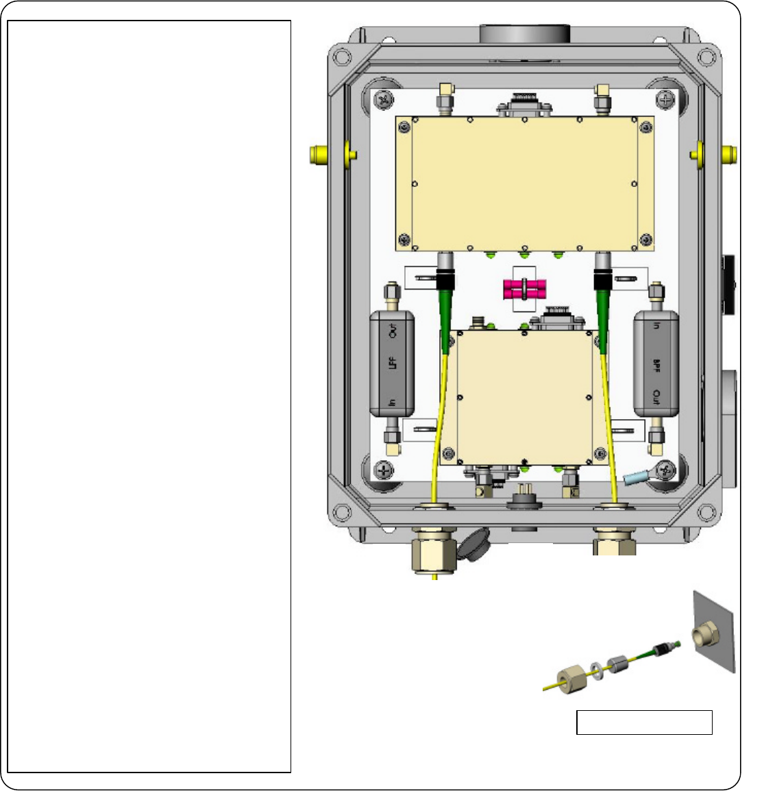
To remove optional 3dB attenuator from remote unit, refer to attached remote
unit diagram, or remote unit lid diagram. Remove power from remote unit. With
3/16” open end crescent wrench, loosen both ends of 3 dB attenuator from
attached RF cable and power amplifier. Remove attenuator, and directly re-connect
RF cable to power amplifier.
Installation Verification
Remote Transceivers To verify correct installation: LED’s L,M,N,O,and P should
all be green when the system is in normal operation. See Remote Transceiver
diagram for LED functions. This system has been designed to provide 20 mW of
RF power at each remote when the BTR-700 set to 100 mW. RF output power can
be increased 3dB by removing the optional 3dB attenuator. See Remote
Transceiver diagram for the location. Power must be removed from the unit before
this option is exercised.
Keep transmit and receive antennas separated 3 feet minimum. One antenna
extension kit is provided for each Remote Transceiver. DO NOT INSTALL
HARDWARE (ANTENNA OR POWER AMPLIFIER) TO BOOST RF OUTPUT
POWER. THIS MAY VIOLATE FCC RULES AND REGULATIONS.
Base Station Transceiver To verify correct installation: Verify system is
connected as shown in System Connection Diagram before power up. On the front
panel a Green LED will indicate that power is present in normal operation.
4 Maintenance
Precaution: All units should be handled observing ESD precautions to prevent
electro-static damages. Disconnect power prior to opening remote units.

A1471 User Manual
FC/APC and RF connections should be cleaned using optics grade Isopropyl
alcohol prior to coupling.
CAUTION: Do not over-tighten connections. Connections should be hand-
tightened plus 1/4 turn.
5 Company Information
Fiber-Span designs and manufactures fiber optic modules used in the transmission
and distribution of RF and wireless signals. Fiber-Span’ s fiber optic transmitters,
receivers and transceivers are widely used in wireless and RF systems worldwide
by wireless systems OEM’s, systems integrators and military systems designers to
capitalize on the inherent advantages of fiber. Fiber has extremely low RF
attenuation (< 1dB/km), very high bandwidth, immunity to EMI, no signal egress,
flat broadband delay characteristics plus a cable design that is light weight and
small size.
Fiber-Span
One Possumtown Road
Piscataway, NJ 08854
732.564.9000
732.564.1990 FAX
Internet
http://www.fiber-span.com
techinfo@fiber-span.com
Attached Drawings / Documents:
Remote Unit Component Diagram
Remote Unit Fiber Installation Guide
700-800_frequency_Plan
BTR-TR-700-800_Freq_Info
C
D
B
C
E
F
F
G
H: top
I: Bottom
J
K
L
M
N
O
O
P
P
Fiber Installation Guide:
a) Unscrew large nut from bulkhead strain relief body.
b) Remove pressure washer and stopper from
bulkhead.
c) Do not remove bulkhead strain relief body from
enclosure.
d) Pass FC connector through nut and pressure washer.
e) Pull open slit in stopper, and pass fiber jacket to
center of stopper. Use care to prevent damage to fiber.
f) Seat stopper into bulkhead.
g) Adjust fiber to desired length inside enclosure by
carefully pulling fiber cable through stopper. Allow slight
fiber slack in enclosure.
h) Insert pressure washer into nut.
i) Tighten nut onto bulkhead body until fiber cable
cannot move.
j) To prevent damage to fiber cable, do n
ot over tighten
nut. Snug finger tight is sufficient to hold cable in place.
Fiber-Span LLC
www.fiber-span.com
AC3101-BTR-RM
Fiber Optic Remote
Transceiver
Lid and cabling not shown for
clarity.
Remove power at “A” before
servicing.
A.
Power Connection: +12V
B. Optical In
C. Optical Out
D. Transmit TNC RF Out
E. Receive TNC RF In
F. Vents
G. Fiber Optic Transceiver
H. Low Noise Amplifier (LNA)
I. Power Amplifier (PA)
J. Band Pass Filter (BPF)
K. Low Pass Filter (LPF)
L. Laser Overcurrent Alarm LED
On: No Alarm
Off: Laser Overcurrent Alarm
M. Transceiver DC Power LED
On: DC Power On
Off: DC Power Off
N. Received Optical Power LED
On: No Alarm
Off: Low Optical Input Power
O. Amplifier DC Power LEDs
On: DC Power On
Off: DC Power Off
P. Amplifier Failure Status LEDs
On: No Alarm
Off: Amplifier Failure
B
A
Fiber Installation Guide
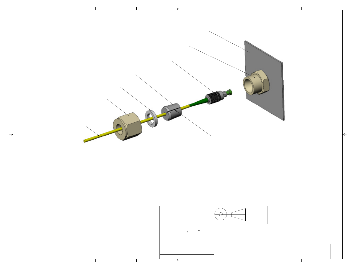
Fiber Cable
Jacket
Nut
Pressure Washer
Stopper
FC Connector
Bulkhead Strain
Relief Body
Enclosure Wall
Stopper Slit
Notes:
a) Unscrew large nut from bulkhead strain relief body.
b) Remove pressure washer and stopper from bulkhead.
c) Do not remove bulkhead strain relief body from enclosure.
d) Pass FC connector through nut and pressure washer.
e) Pull open slit in stopper, and pass fiber jacket to center of stopper.
Use care to prevent damage to fiber.
f) Seat stopper into bulkhead.
g) Adjust fiber to desired length inside enclosure by carefully
pulling fiber cable through stopper. Allow slight fiber slack
in enclosure.
h) Insert pressure washer into nut.
i) Tighten nut onto bulkhead body until fiber cable cannot move.
j) To prevent damage to fiber cable, do not overtighten nut. Snug
finger tight is sufficient to hold cable in place.
A
B
C
D
1
2
3
456
7
8
A
B
C
D
12
3
4
5
6
7
8
Size
A
Fiber-Span, LLC
1 Possumtown Road
Piscataway, NJ 08854
Units are inches unless
otherwise noted.
Tolerances as shown
unless noted:
Tol. Linear: X.XXX 0.005
Tol. Angle: 1
Material:
Date Created: 27-Mar-03 Rev
1
Dwg No.
CAGE
0Z4Y2 7010-0027
Drawn by: J. McSpiritt
Sheet 1 of 1
Procedure, Assembling FC Fiber
Connectors Through Bulkhead
Strain Relief Type 5540-6003
Third
Angle
Projection

BTR-700 A2.xls
BTR-700 A2 9/13/2002
Rev 1 BTR 700 CHANNEL MAP
Base Tx Groups 25 - 36 are user-programmable and are blank initially.
518 524 524 530 530 536
Bp Tx The BTR-700 band plan is the same as the BTR-800 except
632 638 638 644 644 650 BTR-800 transmitter 1 (Ch A) frequencies not used.
Pair Groups = 24 (12a + 12b)
Group 1a 1b 2a 2b 3a 3b 4a 4b 5a 5b 6a 6b 7a 7b 8a 8b 9a 9b
Tx 22 22 23 23 24 24 22 22 23 23 24 24 22 22 23 23 24 24
1522.3 521.5 528.3 527.5 534.3 533.5 522.6 520.7 528.6 527.7 534.6 533.7 523.3 520.6 529.4 526.4 534.6 533.7
Rx 41,42,43 41,42,43 41,42,43 41,42 41,42 41,42 42,43 42,43 42,43
1632.2 632.2 632.2 632.2 632.2 632.2 632.5 632.5 632.5 632.5 632.5 632.5 638.5 638.5 638.5 638.5 638.5 638.5
2632.7 632.7 632.7 632.7 632.7 632.7 632.8 632.8 632.8 632.8 632.8 632.8 638.8 638.8 638.8 638.8 638.8 638.8
3634.5 634.5 634.5 634.5 634.5 634.5 633.3 633.3 633.3 633.3 633.3 633.3 640.7 640.7 639.9 639.9 639.3 639.3
4637 637 637 637 637 637 635.6 635.6 635.6 635.6 635.6 635.6 642 642 642 642 641.6 641.6
5640 640 640 640 640 640 637.6 637.6 637.6 637.6 637.6 637.6 644.3 644.3 644 644 643.6 643.6
6643.5 643.5 643.5 643.5 643.5 643.5 640.1 640.1 640.1 640.1 640.1 640.1 646.3 646.3 646.5 646.5 646.1 646.1
7644.7 644.7 644.7 644.7 644.7 644.7 641.3 641.3 641.3 641.3 641.3 641.3 648 648 648.8 648.8 647.3 647.3
8648.4 648.4 648.4 648.4 648.4 648.4 642.8 642.8 642.8 642.8 642.8 642.8 648.8 648.8 649.6 649.6 648.8 648.8
9******************
10 ******************
Single Groups = 12
Group 10a 10b 11a 11b 12a 12b 13 14 15 16 17 18 19 20 21 22 23 24
Tx 22 22 23 23 24 24 22 23 24 22 23 24 22 23 24 22 23 24
1522 522.7 528 528.7 534 534.7 521.5 527.1 533.7 522.6 528.6 534.6 522.6 528.6 534.6 522.6 528.6 534.6
Rx 41,43 41,43 41,43 41,42,43 41,42,43 41,42,43 41 41 41 42 42 42 43 43 43
1632.1 632.1 632.1 632.1 632.1 632.1 632.1 632.2 632.3 632.2 632.2 632.2 638.2 638.2 638.2 644.2 644.2 644.2
2632.4 632.4 632.4 632.4 632.4 632.4 632.5 632.7 632.7 632.7 632.7 632.7 638.7 638.7 638.7 644.7 644.7 644.7
3632.9 632.9 632.9 632.9 632.9 632.9 634.4 636.3 635 633.4 633.4 633.4 639.4 639.4 639.4 645.4 645.4 645.4
4635.2 635.2 635.2 635.2 635.2 635.2 637.8 637.5 637.5 636.1 636.1 636.1 642.1 642.1 642.1 648.1 648.1 648.1
5636.9 636.9 636.9 636.9 636.9 636.9 641.5 641.2 643 *********
6637.8 637.8 637.8 637.8 637.8 637.8 642.9 644.1 644.7 *********
7644.5 644.5 644.5 644.5 644.5 644.5 645.9 646.6 647.7 *********
8647.5 647.5 647.5 647.5 647.5 647.5 647.1 649.6 649.6 *********
9******************
10 ******************
A2 Band
22 23 24
434241
8/1/2001

BTR-700 B4.xls
BTR-700 B4 9/13/2002
Rev 1 BTR 700 CHANNEL MAP
Base Tx Groups 25 - 36 are user programmable and are blank initially.
536 542 542 548 548 554
Bp Tx The BTR-700 band plan is the same as the BTR-800 except
668 674 674 680 680 686 BTR-800 transmitter 1 (Ch A) frequencies not used.
Pair Groups = 24 (12a + 12b)
Group 1a 1b 2a 2b 3a 3b 4a 4b 5a 5b 6a 6b 7a 7b 8a 8b 9a 9b
Tx 25 25 26 26 27 27 25 25 26 26 27 27 25 25 26 26 27 27
1540.3 539.5 546.3 545.5 552.3 551.5 540.6 538.7 546.6 545.7 552.6 551.7 541.3 538.6 547.4 544.4 552.6 551.7
Rx 47,48,49 47,48,49 47,48,49 47, 48 47, 48 47, 48 48, 49 48, 49 48, 49
1668.2 668.2 668.2 668.2 668.2 668.2 668.5 668.5 668.5 668.5 668.5 668.5 674.5 674.5 674.5 674.5 674.5 674.5
2668.7 668.7 668.7 668.7 668.7 668.7 668.8 668.8 668.8 668.8 668.8 668.8 674.8 674.8 674.8 674.8 674.8 674.8
3670.5 670.5 670.5 670.5 670.5 670.5 669.3 669.3 669.3 669.3 669.3 669.3 676.7 676.7 675.9 675.9 675.3 675.3
4673 673 673 673 673 673 671.6 671.6 671.6 671.6 671.6 671.6 678 678 678 678 677.6 677.6
5676 676 676 676 676 676 673.6 673.6 673.6 673.6 673.6 673.6 680.3 680.3 680 680 679.6 679.6
6679.5 679.5 679.5 679.5 679.5 679.5 676.1 676.1 676.1 676.1 676.1 676.1 682.3 682.3 682.5 682.5 682.1 682.1
7680.7 680.7 680.7 680.7 680.7 680.7 677.3 677.3 677.3 677.3 677.3 677.3 684 684 684.8 684.8 683.3 683.3
8684.4 684.4 684.4 684.4 684.4 684.4 678.8 678.8 678.8 678.8 678.8 678.8 684.8 684.8 685.6 685.6 684.8 684.8
9******************
10 ******************
Single Groups = 12
Group 10a 10b 11a 11b 12a 12b 13 14 15 16 17 18 19 20 21 22 23 24
Tx 25 25 26 26 27 27 25 26 27 25 26 27 25 26 27 25 26 27
1540 540.7 546 546.7 552 552.7 539.5 545.1 551.7 540.6 546.6 552.6 540.6 546.6 552.6 540.6 546.6 552.6
Rx 47, 49 47, 49 47, 49 47,48,49 47,48,49 47,48,49 47 47 47 48 48 48 49 49 49
1668.1 668.1 668.1 668.1 668.1 668.1 668.1 668.2 668.3 668.2 668.2 668.2 674.2 674.2 674.2 680.2 680.2 680.2
2668.4 668.4 668.4 668.4 668.4 668.4 668.5 668.7 668.7 668.7 668.7 668.7 674.7 674.7 674.7 680.7 680.7 680.7
3668.9 668.9 668.9 668.9 668.9 668.9 670.4 672.3 671 669.4 669.4 669.4 675.4 675.4 675.4 681.4 681.4 681.4
4671.2 671.2 671.2 671.2 671.2 671.2 673.8 673.5 673.5 672.1 672.1 672.1 678.1 678.1 678.1 684.1 684.1 684.1
5672.9 672.9 672.9 672.9 672.9 672.9 677.5 677.2 679 *********
6673.8 673.8 673.8 673.8 673.8 673.8 678.9 680.1 680.7 *********
7680.5 680.5 680.5 680.5 680.5 680.5 681.9 682.6 683.7 *********
8683.5 683.5 683.5 683.5 683.5 683.5 683.1 685.6 685.6 *********
9******************
10 ******************
494847
B4 Band
7/23/2002
25 26 27

BTR-700 C6.xls
BTR-700 C6 9/13/2002
Rev 2 BTR 700 CHANNEL MAP
Base Tx Groups 25 - 36 are user programmable and are blank initially.
554 560 560 566 566 572
Bp Tx The BTR-700 band plan is the same as the BTR-800 except
704 710 710 716 716 722 BTR-800 transmitter 1 (Ch A) frequencies not used.
Pair Groups = 24 (12a + 12b)
Group 1a 1b 2a 2b 3a 3b 4a 4b 5a 5b 6a 6b 7a 7b 8a 8b 9a 9b
Tx 28 28 29 29 30 30 28 28 29 29 30 30 28 28 29 29 30 30
1558.3 557.5 564.3 563.5 570.3 569.5 558.6 556.7 564.6 563.7 570.6 569.7 559.3 556.6 565.4 562.4 570.6 569.7
Rx 53,54,55 53,54,55 53,54,55 53,54 53,54 53,54 54,55 54,55 54,55
1704.2 704.2 704.2 704.2 704.2 704.2 704.5 704.5 704.5 704.5 704.5 704.5 710.5 710.5 710.5 710.5 710.5 710.5
2704.7 704.7 704.7 704.7 704.7 704.7 704.8 704.8 704.8 704.8 704.8 704.8 710.8 710.8 710.8 710.8 710.8 710.8
3706.5 706.5 706.5 706.5 706.5 706.5 705.3 705.3 705.3 705.3 705.3 705.3 712.7 712.7 711.9 711.9 711.3 711.3
4709 709 709 709 709 709 707.6 707.6 707.6 707.6 707.6 707.6 714 714 714 714 713.6 713.6
5712 712 712 712 712 712 709.6 709.6 709.6 709.6 709.6 709.6 716.3 716.3 716 716 715.6 715.6
6715.5 715.5 715.5 715.5 715.5 715.5 712.1 712.1 712.1 712.1 712.1 712.1 718.3 718.3 718.5 718.5 718.1 718.1
7716.7 716.7 716.7 716.7 716.7 716.7 713.3 713.3 713.3 713.3 713.3 713.3 720 720 720.8 720.8 719.3 719.3
8720.4 720.4 720.4 720.4 720.4 720.4 714.8 714.8 714.8 714.8 714.8 714.8 720.8 720.8 721.6 721.6 720.8 720.8
9******************
10 ******************
Single Groups = 12
Group 10a 10b 11a 11b 12a 12b 13 14 15 16 17 18 19 20 21 22 23 24
Tx 28 28 29 29 30 30 28 29 30 28 29 30 28 29 30 28 29 30
1558 558.7 564 564.7 570 570.7 557.5 563.1 569.7 558.6 564.6 570.6 558.6 564.6 570.6 558.6 564.6 570.6
Rx 53,55 53,55 53,55 53,54,55 53,54,55 53,54,55 53 53 53 54 54 54 55 55 55
1704.1 704.1 704.1 704.1 704.1 704.1 704.1 704.2 704.3 704.2 704.2 704.2 710.2 710.2 710.2 716.2 716.2 716.2
2704.4 704.4 704.4 704.4 704.4 704.4 704.5 704.7 704.7 704.7 704.7 704.7 710.7 710.7 710.7 716.7 716.7 716.7
3704.9 704.9 704.9 704.9 704.9 704.9 706.4 708.3 707 705.4 705.4 705.4 711.4 711.4 711.4 717.4 717.4 717.4
4707.2 707.2 707.2 707.2 707.2 707.2 709.8 709.5 709.5 708.1 708.1 708.1 714.1 714.1 714.1 720.1 720.1 720.1
5708.9 708.9 708.9 708.9 708.9 708.9 713.5 713.2 715 *********
6709.8 709.8 709.8 709.8 709.8 709.8 714.9 716.1 716.7 *********
7716.5 716.5 716.5 716.5 716.5 716.5 717.9 718.6 719.7 *********
8719.5 719.5 719.5 719.5 719.5 719.5 719.1 721.6 721.6 *********
9******************
10 ******************
555453
5/29/2001
C6 Band
28 29 30
12/17/01
700/800 Systems
Frequency Selection Rules
1. Frequency Spacing……………..…Keep all BTR/TR receive and transmit frequencies at least 300kHz away from
each other, >400kHz preferred. Both the transmitters and receivers should be
at least 400kHz away from other RF equipment.
2. IM Products………….…………… 2 transmitter 3rd orders by at least 100kHz (200kHz preferred)
3 transmitter 3rd orders by at least 50kHz (100kHz preferred)
2 transmitter 5th orders by at least 50kHz (100kHz preferred)
3. Transmitter Sidebands……...…… Avoid base and beltpack carrier sidebands: +/-200kHz, +/-400 and +/-600.
Keep at least 50kHz away from these frequencies.
4. Bandwidths………………….……. Transmitter bandwidth = 150kHz
Receiver bandpass = 230kHz
5. Base RX 4MHz Image Harmonics. C6 frequencies to avoid are 704.4, 708.4, 712.4, 716.4, 720.4.
A2 frequencies to avoid are 632.4, 636.4, 640.4, 644.4, 648.4.
Avoid the frequencies, by at least 50kHz
6. Base LO1 Xtal harmonics……...… Avoid C6 Xtal harmonics; 524.667, 655.833, 787.000 by at least 50kHz .
Avoid A2 Xtal harmonics; 476.667, 595.833, 715.000 by at least 50kHz.
FYI
TR-700/800 Oscillators/IFs – Dual Conversion Superheterodyne, Synthesized, FM
LO1…………...……….… Synthesized (If set on correct frequency then, LO1 = RFIN – 65.7)
LO2……………………… 55MHz, Xtal, Fixed
Master Oscillator….…..… 4MHz, Xtal, trimmer adjust
IF1……………….………. 65.7MHz
IF2…………………….…. 10.7MHz
Transmitter……………….Synthesized, FM
BTR-700/800 Oscillators/IFs - Dual Conversion Superheterodyne, Synthesized, FM
LO1……………………… X MHz, x6 Xtal Osc., Fixed
1 Band……….… X = 697MHZ
2 Band……….… X = 715MHz
3 Band……….… X = 733MHZ
4 Band……….… X = 751MHZ
5 Band……….… X = 769MHz
6 Band……….… X = 787MHZ
7 Band……….… X = 805MHZ
Examples: A C6 system’s LO1 is set to the Band 6 (787MHz) frequency. An A2 system’s LO1 is set to the Band 2
(715MHz) frequency.
LO2……………...…….… Synthesized, 75.8 to 93.6MHz. (If set on correct frequency then, LO2 = LO1 - RFIN + 10.7)
Master Oscillator...……… 4MHz, Xtal, trimmer adjust
IF1……………….………. 65 – 83MHz
IF2…………….…………. 10.7MHz
Transmitter(s)…………… Synthesized, FM
Page 1 of 1