Fiber Span FS31-15C Booster User Manual
Fiber-Span LLC Booster
user manual
3434 Rt. 22W ▪ Suite 140 Branchburg, NJ 08876
908.253.9080 ▪ fiber-span.com
User Manual
FS31R-15C VHF RRU
162 – 175 MHz Fiber-Fed Remote Repeater Unit (RRU)
4 Watts Linear Output Power
Version 3
5/1/2012

3434 Rt. 22W ▪ Suite 140 Branchburg, NJ 08876
908.253.9080 ▪ fiber-span.com
1. Limitation of Liability
Copyright 2011 Fiber-Span. All rights reserved. No part of this publication, or any software
included with it may be reproduced, stored in a retrieval system, or transmitted in any form or by
any means, including photocopying, electronic, mechanical, recording or otherwise, without the
prior written permission of the copyright holder.
Fiber-Span provides this document as is, without any warranty of any kind either expressed or
implied including, but not limited to, the implied warranties of merchantability and fitness of a
particular purpose. Fiber-Span may make changes or improvements in the equipment, software,
or specifications described in this document at any time and without notice. These changes will
be incorporated in new releases of this document.
This document may contain technical inaccuracies or typographical errors. Fiber-Span waives
responsibility for any labor, materials, or costs incurred by any person or party as a result of
using this document. Fiber-Span and any of its affiliates shall not be liable for any damages
(including, but not limited to, consequential, indirect or incidental, special damages or loss of
profits or date) even if they were foreseeable and Fiber-Span has been informed of their potential
occurrence, arising out of or in connection with this document or its use.
Fiber-Span
3434 Route 22 W.
Branchburg, New Jersey
08876
Tel: (908) 253-9080
Fax: (908) 253-9086
www.fiber-span.com

3434 Rt. 22W ▪ Suite 140 Branchburg, NJ 08876
908.253.9080 ▪ fiber-span.com
-This page intentionally left blank-

1 3434 Rt. 22W ▪ Suite 140 Branchburg, NJ 08876
908.253.9080 ▪ fiber-span.com
2. Introduction
The FS31R-15C Very High Frequency (VHF) Fiber Optic Remote Repeater Unit (FO-RRU) is a
linear 4 Watts (36 dBm) RF power amplifier covering the frequency range from 162 to 175
MHz. The unit offers fiber input / output interface for long haul operation through a single mode
fiber medium.
Device improves in-building wireless coverage enhancement to eliminate dropped calls and poor
reception by amplifying and re-broadcasting a cell tower signal throughout a building.
While the fiber section is bandwidth unlimited, the internal RF components are optimized for
best operation in the VHF bandwidth. RF has a separate input and output port to accommodate
simplex application; however this product series can contain a duplexer for a bi-directional
configuration ensuring uplink and downlink into a distributive antenna system (DAS).
3. Revision History
Version
Description
Date
Author
1
Draft release
5/1/2012
C.M.
2
Update FCC Statement
24-May-12
J.S.
3
Changed MPI distances to 1.5 and 2.5 meters
31-May-2012
J.S.

2 3434 Rt. 22W ▪ Suite 140 Branchburg, NJ 08876
908.253.9080 ▪ fiber-span.com
4. Table of Contents
1. Limitation of Liability............................................................................................................. 1
2. Introduction ............................................................................................................................. 1
3. Revision History ..................................................................................................................... 1
4. Table of Contents .................................................................................................................... 2
5. Warnings ................................................................................................................................. 4
6. Main Product Name ................................................................................................................ 5
7. Sub Product Name .................................................................................................................. 5
8. System Application ................................................................................................................. 6
9. Startup Checklist ..................................................................................................................... 7
10. Installation............................................................................................................................ 7
10.1. Connecting RF ............................................................................................................ 7
10.2. Mounting installation .................................................................................................. 8
11. Block Diagram ..................................................................................................................... 8
12. Specifications ....................................................................................................................... 9
12.1. Electrical ..................................................................................................................... 9
12.2. Mechanical ................................................................................................................ 11
Wall Mount Version ............................................................................................................. 11
Rack Mount Version ............................................................................................................. 11
12.3. Tools ......................................................................................................................... 11
12.4. On Site Requirements ............................................................................................... 12
13. General Precautions ........................................................................................................... 12
14. Maintenance ....................................................................................................................... 12

3 3434 Rt. 22W ▪ Suite 140 Branchburg, NJ 08876
908.253.9080 ▪ fiber-span.com
14.1. Preventative Measure for Optimal Operation ........................................................... 13
15. Factory Settings ................................................................................................................. 15
16. Outline Drawing................................................................................................................. 16
17. Front / Rear Panel Ports and Interfaces............................................................................. 18
18. FCC Statement ................................................................................................................... 20
19. Warranty ............................................................................................................................ 21
19.1. General Warranty ...................................................................................................... 21
19.2. Limitations of Warranty ............................................................................................ 21
19.3. Limitations of Damages ............................................................................................ 21
19.4. Return Material Authorization (RMA) ..................................................................... 21
20. Company Information ........................................................................................................ 22
Appendix A FS31R-15C RRU Media Converter ................................................ A-1
4 3434 Rt. 22W ▪ Suite 140 Branchburg, NJ 08876
908.253.9080 ▪ fiber-span.com
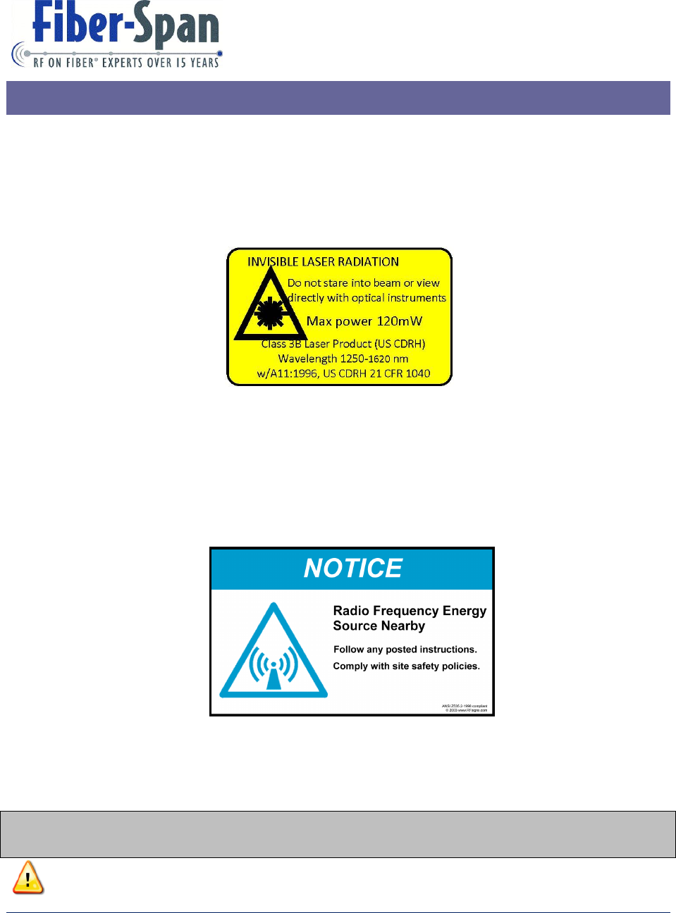
5. Warnings
Invisible laser radiation exits from areas labeled “Aperture”
By connecting all the fiber connector ends of the optical link before applying power to both
fiber transceiver unit and remote fiber node, it will prevent exposure to invisible laser
radiation.
Follow and comply with all site safety policies, local codes and rules ordinances.
Figure 2: Radio Frequency Notice
** Pay special attention to statements with an exclamation point symbol next to it. **
Terminate every RF port with a 50 Ohm load.
38
RF Signs
Sign Examples
Figure 1: Laser Warning Label
5 3434 Rt. 22W ▪ Suite 140 Branchburg, NJ 08876
908.253.9080 ▪ fiber-span.com
While in operation do not touch heat sink as surface is very HOT.
Device maximum composite optical input level is 7 dBm.
Only a qualified technician shall be allowed to operate the unit, after reading and
understanding all the guidelines in this manual.
6. Main Product Name
There are two (2) main product versions:
Model Prefix
Model Midfix
Version
FS31R-15C
WM
Wall Mount
FS31R-15C
RM
Rack Mount
7. Sub Product Name
Major Internal Parts:
Part Number
Description
Quantity
180-0113
Gigabit Media Converter
1
180-0117
SFP Module
1
290-0310
DL Variable Digital Amplifier
1
290-0311
UL Variable Digital Amplifier
1
305-0359
Micro-Processor Computer
1
305-0361
Controller Board
1
390-0063
Dual WDM
1
495-0098
VHF High Power Amplifier
1
530-0169
VHF Duplexer
1
650-0043
12 Volt Fan (2 as inlet, 2 as outlet)
4

6 3434 Rt. 22W ▪ Suite 140 Branchburg, NJ 08876
908.253.9080 ▪ fiber-span.com
Part Number
Description
Quantity
290-0061
Fiber Optic Transmitter / Receiver
1
The main parts are the same for the wall mount and rack mount versions excluding the RF cable
interfaces and wiring harnesses that vary in length. Some or all the parts are subject to change
without notice for the purpose of improving the product functionality.
8. System Application
The RRU is mounted in a strategic remote location where signal communication is poor or none
available determined by the system engineer assessment and is part of a large system
configuration with a headend. Integrated at the headend are elements that transmit, receive,
condition and transport signals simultaneously via two (2) dedicated single mode fiber medium
into an RRU and signal distributed and repeated for every remote unit.
One (1) fiber medium is for the downlink path and the other fiber medium is for the uplink path
optical interface ports RRU which is design for long haul up to 10 dBo of optical loss translating
into a useable uninterrupted fiber-distance of 28.5 Kilometers.
Downlink signals at the headend are condition by the base station unit (BSU) which accepts an
input power from the RF source between 0 dBm to 30 dBm and outputs signal levels of 0 dBm
with nominal at -10 dBm into the fiber transmitter unit.
A network management system (NMS) controls and configures the main elements the headend
location as well as the RRU hardware via dedicated Ethernet LAN internet connections within
the same fiber backbone. Lost of communication to and from the system is reported and logged
with the NMS.

7 3434 Rt. 22W ▪ Suite 140 Branchburg, NJ 08876
908.253.9080 ▪ fiber-span.com
9. Startup Checklist
The rack mount version unit has a VAC inlet that comes with a six (6) feet 3 prong VAC cord
and the wall mount version unit has an embedded six (6) feet 3 prong VAC cord that plugs to a
common house hold AC outlet.
To protect the device RF output port, it includes a 50 Ohm load terminator that should not be
removed until the RF output cable is ready to connect to it.
10. Installation
10.1. Connecting RF
Follow these steps for connecting and disconnecting RF cables to the unit.
Sequence to connect:
1. Connect output load to the unit.
2. Apply power to the device.
3. Verify RF signal source is turned off.
4. Connect RF Input to the unit. (when fiber-fed, connect optical input to the unit).
5. Turn on the RF signal source input.
Sequence to Disconnect:
1. Turn off the source RF input.
2. Disconnect the RF Input connection of the unit. (when fiber-fed, disconnect optical input
to the unit).
3. Un-apply power to the unit.
4. Disconnect the output load of the unit.
8 3434 Rt. 22W ▪ Suite 140 Branchburg, NJ 08876
908.253.9080 ▪ fiber-span.com
10.2. Mounting installation
In a well structured support wall that it is reinforced with a 1 inch thick plywood of additional
backing, mount the enclosure using four (4) socket head cap screws size 3/8”-16, 1-1/2 inch
length to bear the enclosure weight (80 lbs).
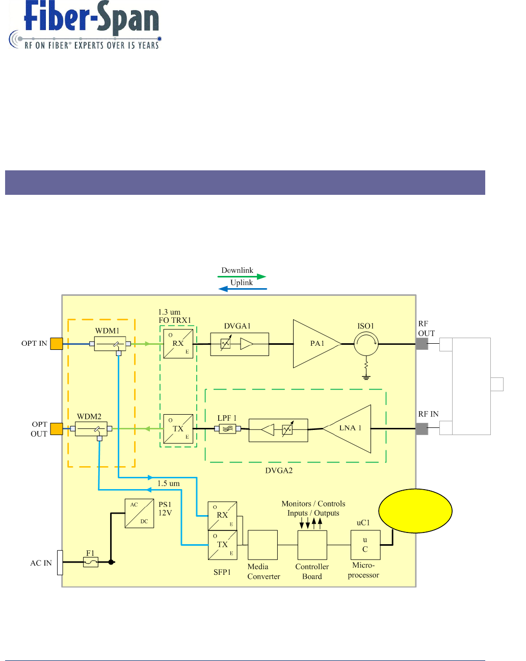
11. Block Diagram
The FS31R-15 rack mount and wall mount unit internal parts are the same without internal
duplexer is shown in Figure 3: Remote Repeater Unit (RRU) Block Diagram. Unit choices are
with internal or external duplexer.
1 GHz
Clock
Figure 3: Remote Repeater Unit (RRU) Block Diagram
Duplexer
RF
In/Out
9 3434 Rt. 22W ▪ Suite 140 Branchburg, NJ 08876
908.253.9080 ▪ fiber-span.com
12. Specifications
12.1. Electrical
Dowlink Path
RF Parameters
Acronym
Min
Typical
Max (1)
Units
Composite RF Input (2)
RFin
-15
-10
dBm
Frequency
Freq
169.5625
--
173.825
MHz
Flatness
Flts
--
--
+/- 2.0
dB
RF Gain (3)
RFG
48
50
56
dB
Output Intercept Point
OIP3
56.5
61.0
--
dBm
Output Noise
O.N.
-114
-90
-75
dBm/1Hz
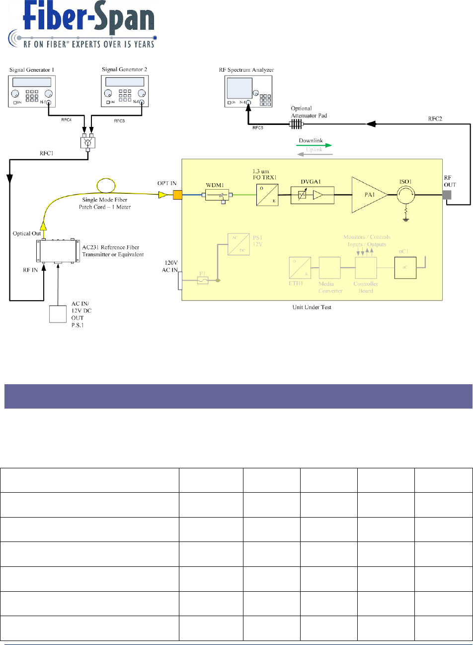
Figure 4: UUT Downlink Test Setup Block Diagram
10 3434 Rt. 22W ▪ Suite 140 Branchburg, NJ 08876
908.253.9080 ▪ fiber-span.com
Composite RF Out and Automatic
Level Control
ALC
36.0
37
dBm
Forward Power Alarm
FPM
39
40
dBm
Test Frequencies
F1/F2
172.000 – 172.500
MHz
Calculated Values
Spur Free Dynamic Range
SFDR
100
dBm/2/3
Hz
Uplink Path
RF Parameters
Acronym
Min
Typical
Max (1)
Units
RF Input (4), (5)
RFin
-80
-55
-19
dBm
Frequency
Freq
162.175
166.4375
MHz
Flatness
--
--
+/- 2.00
dB
RF Gain (3)
-7
56
dB
RF Out
0
3
dBm
Output Noise
-115
dBm/2/3Hz
Test Frequencies
F1, F2
164.000 – 164.500
MHz
Calculated Values
Spur Free Dynamic Range
SFDR
100
dBm/2/3
Hz
Noise Figure
NF
2
8
--
(1) The electrical test conditions specified in this section is with a reference calibrated in factory
unit using a 1 meter single mode fiber patch cord as the fiber medium equivalent to 0 dBo optical
loss.
(2) RF Input level is using a reference transmitter.
(3) RF Gain measurement criteria are with attenuators at minimum attenuation.

11 3434 Rt. 22W ▪ Suite 140 Branchburg, NJ 08876
908.253.9080 ▪ fiber-span.com
(4) Uplink RF input level at -20 dBm triggers the squelch and RF will shut off.
(5) Factory test RF input level into reference fiber transmitter is -19 to -23 dBm.
RF Gain Adjustment
RF Gain has a wide adjustment range thus it is set to the minimum value of 37dB at 0 dBo loss
and increases proportionally as the fiber medium optical loss goes up.
Normalization of the Link RF Gain due to increase in optical loss:
Increase up the RF Gain by 2 (dB) for every 1 (dBo) of fiber medium optical
loss.
Before verifying the RF Gain maximum level is attainable, decrease the RF input level by 20 dB,
hence to -57 dBm, so that no compression of signal occurs.
12.2. Mechanical
Wall Mount Version
Allow at least 20 inches of space from the front of the unit (not including
enclosure depth) for opening the door.
Rack Mount Version
Allow at least 20 inches of space from the front of the unit for installation and
removal of the rack mount.
12.3. Tools
Tools
Purpose
Medium/ Large hand held flat head
screwdriver
For opening front door of wall mount
Tip

12 3434 Rt. 22W ▪ Suite 140 Branchburg, NJ 08876
908.253.9080 ▪ fiber-span.com
12.4. On Site Requirements
For each RRU a three (3) wire (Hot, Neutral, and Ground) 120 VAC wall outlet including a
separate earth ground bus bar that connects to the unit chassis.
Two 9/125 um single-mode fiber strands with SC/APC connectors, one for the downlink path
and the other for the uplink path.
A unit as a simplex configuration requires two (2) high quality RF cable with N-Male connector
that attaches from the DAS to the RF Input and Output port.
A unit as a duplex configuration requires only one (1) high quality RF cable with N-Male
connector that attaches from the DAS to the bi-directional RF In/Out port.
13. General Precautions
Allow at least 6 inches of space into the air inlet and outlet of the unit, for proper air flow
through the fan(s).
Do not change any of the parameters unless instructed to do so by an authorized
supervisor and you are a qualified technician to operate device.
Do not attempt to move product without the proper tools and man power, because
product is heavy.
Terminate all the unit RF ports with a 50 Ohm load prior to powering up.
14. Maintenance
Periodically check and clean the unit fan(s) inlet and outlet by removing lint, dust and dirt with a
lightly damped cloth. Air-in-a-Can is also a good product to have as part of a maintenance kit
that includes an extended nozzle for hard to reach places.
Do not hose the unit with water as it is not waterproof.
13 3434 Rt. 22W ▪ Suite 140 Branchburg, NJ 08876
908.253.9080 ▪ fiber-span.com
Unit can be cleaned without being turned off, but do not disrupt or touch any moving mechanism
in a way that can stall the motor.
Replace a fan immediately upon fan alarm indicator turning on. Shut off the unit to preserve the
lifespan when a fan or fans cannot be replaced immediately.
14.1. Preventative Measure for Optimal Operation
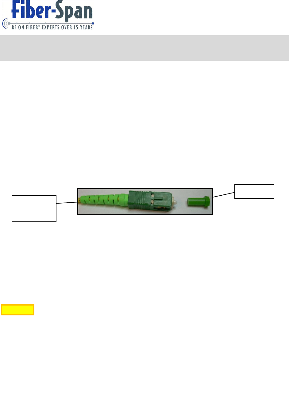
Optical Maintenance
Once optical connectors are secured the ports no maintenance is required. However when
necessary to unplug it, immediately cap the tip with cover, This prevents scratching exposed
glass tip which deteriorates performance and possibly becoming unusable.
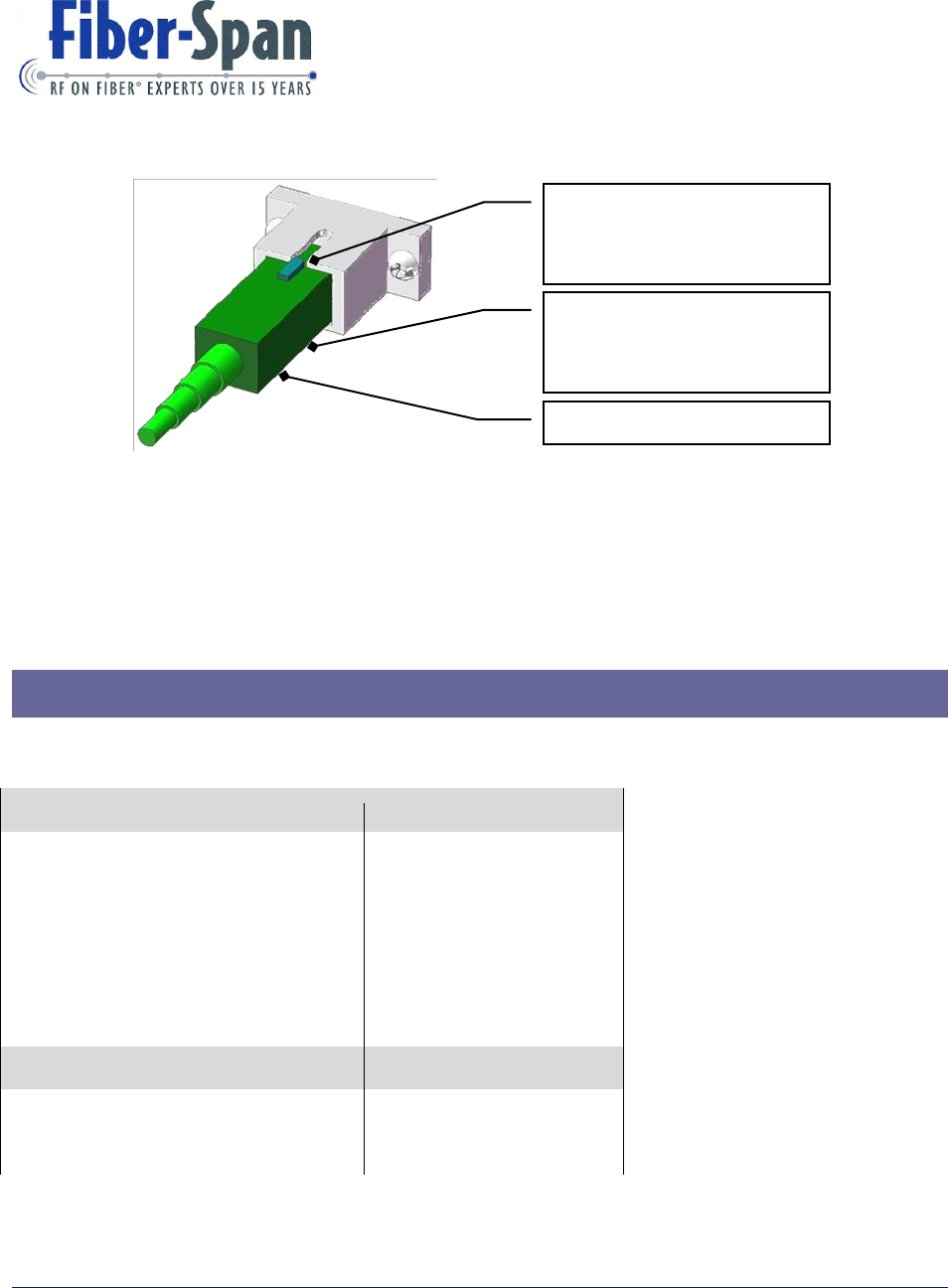
Guidelines for using SC/APC Connectors and Adapters
Warning! Improper maintenance and installation of optical connectors and adapters can
permanently damage parts, and seriously degrade performance of fiber optic devices. All
installation personnel using Fiber-Span equipment equipped with optics should review this
document. Fiber-Span is not responsible for damage caused by improper use of optical
equipment.
Maintenance
Cover
SC/APC
Connector
Figure 5: SC/APC Connector with cap
14 3434 Rt. 22W ▪ Suite 140 Branchburg, NJ 08876
908.253.9080 ▪ fiber-span.com
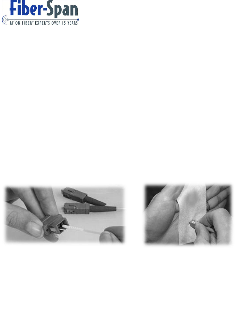
1. Clean SC-APC connectors and Adapters with isopropyl alcohol (99%), dust free fiber
optic cleaning tissues and 2.5mm mini-swabs.
2. While performing these steps protect connector tips from scratching.
3. Clean the inside of the fiber optic adapters and bulkheads using a swab lightly moistened
in isopropyl alcohol.
4. Gently insert swab into the adapter orifice until the back-stop is reached, rotate swab
clockwise several times. Discard swab after each use.
5. Lightly moisten a dust free fiber optic cleaning tissue with isopropyl alcohol.
6. Hold pre-moisten tissue touching connector tip (end face) and gently swipe connector in
a figure “8” motion several times.
7. Always keep exposed connector tip and adapters covered with protective cap.
Figure 6: SC/APC Adapter
Figure 7: SC/APC Connector
Installation
8. Align connector key (alignment post) with notch on the adapter or bulkhead.
9. After assuring keys align, push connector forward into adapter or bulkhead until
connector clicks. Click indicates connector has been seated properly.
15 3434 Rt. 22W ▪ Suite 140 Branchburg, NJ 08876
908.253.9080 ▪ fiber-span.com
10. Always install SC/APC connectors into adapter or bulkhead by hand.
Initial signal testing as a baseline and periodic signal level testing thereafter, will provide a
historical log for keeping track of signal quality so that if required fine tuning of the system can
be achieved for optimum performance.
15. Factory Settings
Tuning and testing performed at factory are:
Two tone test (TTT) that consist of:
S-Parameters
RF Input (dBm)
S21
RF Output (dBm)
S11
RF Gain (dB)
S22
Output Third Order Intercept (dBm)
Output Noise (dBm/ 1Hz)
Calculated Values
Spur Free Dynamic Range (SFDR)
Noise Figure (NF)
Assure key (alignment pin) on
connector aligns with notch in
adapter or bulkhead
Always insert by hand
After key is aligned, push
connector into adapter or
bulkhead
Figure 8: SC/APC Connector attaching to Adapter
16 3434 Rt. 22W ▪ Suite 140 Branchburg, NJ 08876
908.253.9080 ▪ fiber-span.com
Monitors and Controls
Fiber Transmitter
FOTX
Fiber Receiver
FORX
RF
Power Amplifier
Optical power
TX Set-point
Laser Bias
Temperature
Alarm
Optical minimum
input threshold
DL Attenuation Range
UL Attenuation Range
Automatic Level Control
Forward Power Monitor
Sensitivity
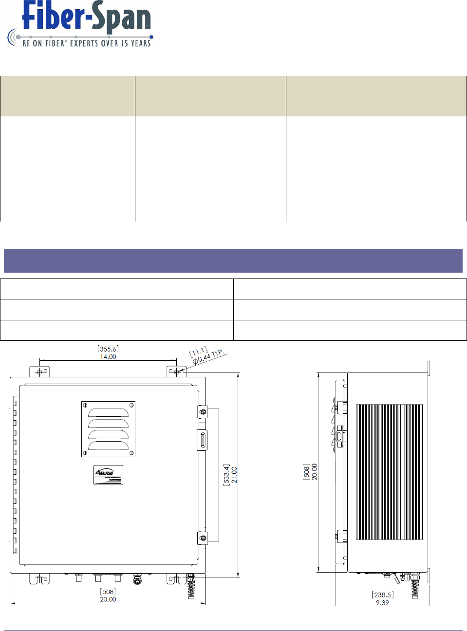
16. Outline Drawing
Enclosure Type
Size inches (mm)
Rack Mount
19 x 18 x 6.95 (465.1 x 457.2 x 6.95)
Wall Mount
20 x 20 x 9 (508 x 508 x 238.5)
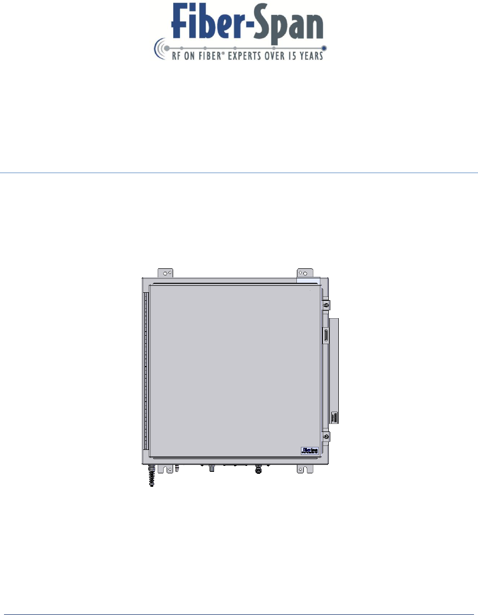
Figure 9: Wall Mount
17 3434 Rt. 22W ▪ Suite 140 Branchburg, NJ 08876
908.253.9080 ▪ fiber-span.com
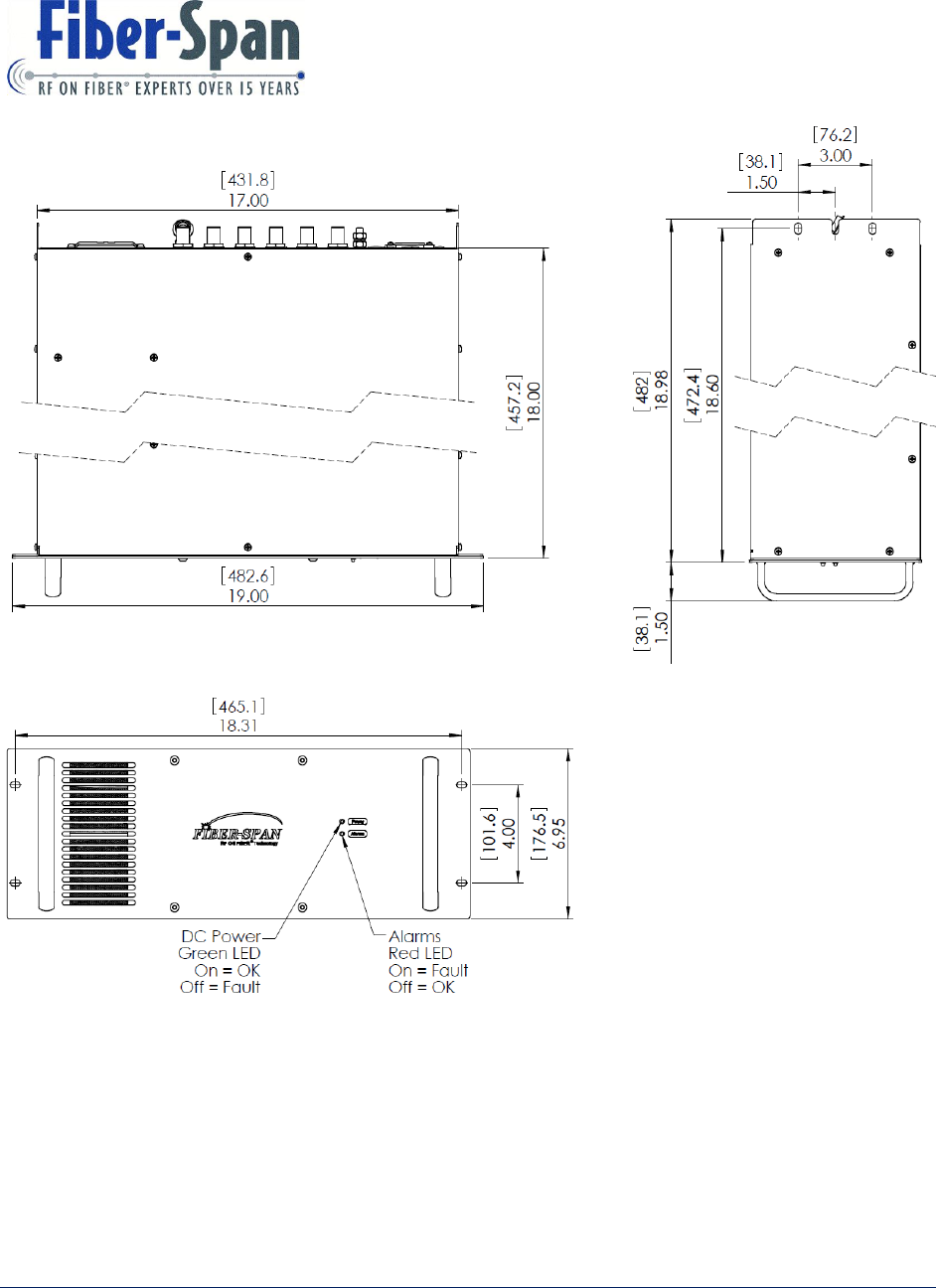
Figure 10: Rack Mount
18 3434 Rt. 22W ▪ Suite 140 Branchburg, NJ 08876
908.253.9080 ▪ fiber-span.com
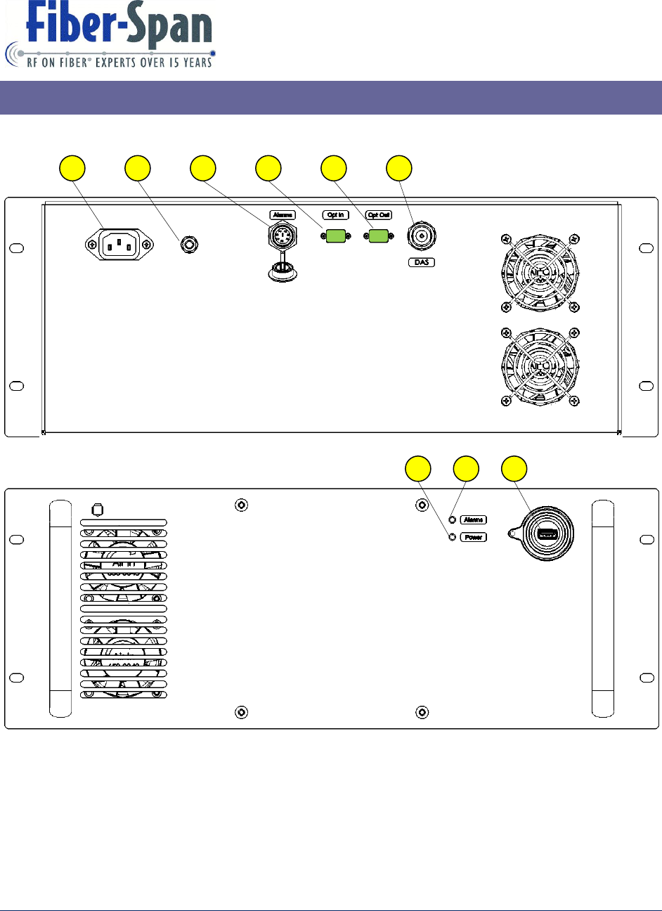
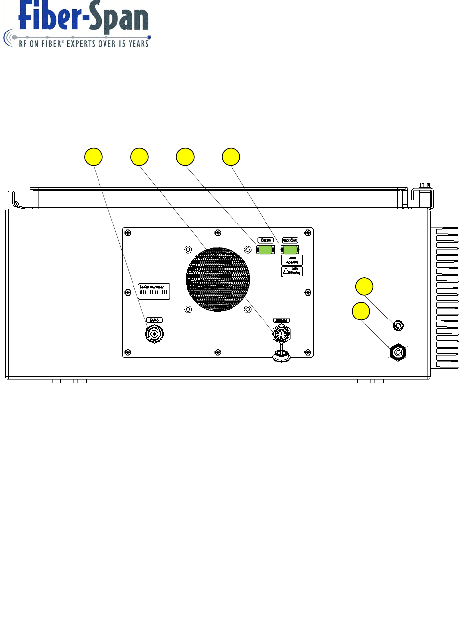
17. Front / Rear Panel Ports and Interfaces
Rack Mount
1. VAC In Inlet
2. Ground Lug
3. Circular Alarm Connector
4. Optical Input Port
5. Optical Output Port
6. RF In / Out Port
7. Power LED Indicator
Rear View
Front View
7
1
2
3
4
5
6
8
9
19 3434 Rt. 22W ▪ Suite 140 Branchburg, NJ 08876
908.253.9080 ▪ fiber-span.com
8. Alarm LED Indicator
9. USB Port
Wall Mount
Bottom Panel Ports and Interface
1. RF In / Out Port
2. Circular Alarm Connector
3. Optical Input Port
4. Optical Output Port
5. VAC Cord
6. Ground Lug
Bottom View
1
2
3
4
5
6

20 3434 Rt. 22W ▪ Suite 140 Branchburg, NJ 08876
908.253.9080 ▪ fiber-span.com
18. FCC Statement
Manufacturers Notes
“Changes or modifications not expressly approved by the manufacturer could “Void” the
user’s authority to operate the equipment”.
This equipment has been tested and found to comply with the limits for a Class A digital
device, pursuant to Part 15 of the FCC Rules. These limits are designed to provide
reasonable protection against harmful interference when the equipment is operated in a
commercial environment. This equipment generates, uses, and can radiate radio frequency
energy and, if not installed and used in accordance with the instructions manual, may cause
harmful interference to radio communications. Operation of this equipment in a residential
area is likely to cause harmful interference in which case the user will be required to
correct the interference at their own expense.
This device has been designated to operate with the antennas having a maximum gain of
[9] dBi for a 1.5 meter distance and antennas having a gain greater than [15] dBi at 2.5
meters distance are strictly prohibited for use with this device. The required antenna
impedance is [50] Ohms.
To improve and correct equipment performance the following can be performed.
1. Re-orient or relocate the receiving antenna.
2. Increase the separation between the equipment and receiver.
3. Connect the equipment into an outlet on a different circuit from that to which the receiver
is connected.
4. Consult the dealer or an experienced radio/RF technician for help.

21 3434 Rt. 22W ▪ Suite 140 Branchburg, NJ 08876
908.253.9080 ▪ fiber-span.com
19. Warranty
19.1. General Warranty
The RFN carries a standard warranty period of one (1) year unless otherwise indicated on the
shipping packages as noted in the purchase order agreement.
19.2. Limitations of Warranty
The warranty is limited to the repair or replacement of the defective product. Fiber-Span will
decide which remedy to provide for defective components as its own discretion. Fiber-Span
shall have a reasonable time after determining that a defective product exists to repair or replace
the problem unit. The warranty applies to repaired or replaced products for the balance of the
applicable period of the original warranty or ninety (90) days from date of shipment of a repaired
or replaced component, whichever is longer.
The Fiber-Span standard warranty does not cover products which have been received improperly
packaged, altered, or physically damaged. For example, broken warranty seal, labels exhibiting
tampering, physically abused enclosure, broken pins on connectors, any modifications made
without Fiber-Span authorization, will void all warranty.
19.3. Limitations of Damages
The liability for any defective product shall in no event exceed the purchase price for the
defective product. Fiber-Span has no liability for general, consequential, incidental or special
damages.
19.4. Return Material Authorization (RMA)
No product may be returned directly to Fiber-Span without first getting an approval from Fiber-
Span. If it is determined that the product may be defective, you will be given an RMA number
and instructions in how to return the product. An unauthorized return, i.e., one for which an
RMA number has not been issued, will be returned to you at your expense. Authorized returns
are to be shipped to the address on the RMA in an approved shipping container. It is suggested
that the original box and packaging materials should be kept if a defective product needs to be
shipped back to Fiber-Span. To request an RMA, please call 908.253.9080.
22 3434 Rt. 22W ▪ Suite 140 Branchburg, NJ 08876
908.253.9080 ▪ fiber-span.com
20. Company Information

A-1 3434 Rt. 22W ▪ Suite 140 Branchburg, NJ 08876
908.253.9080 ▪ fiber-span.com
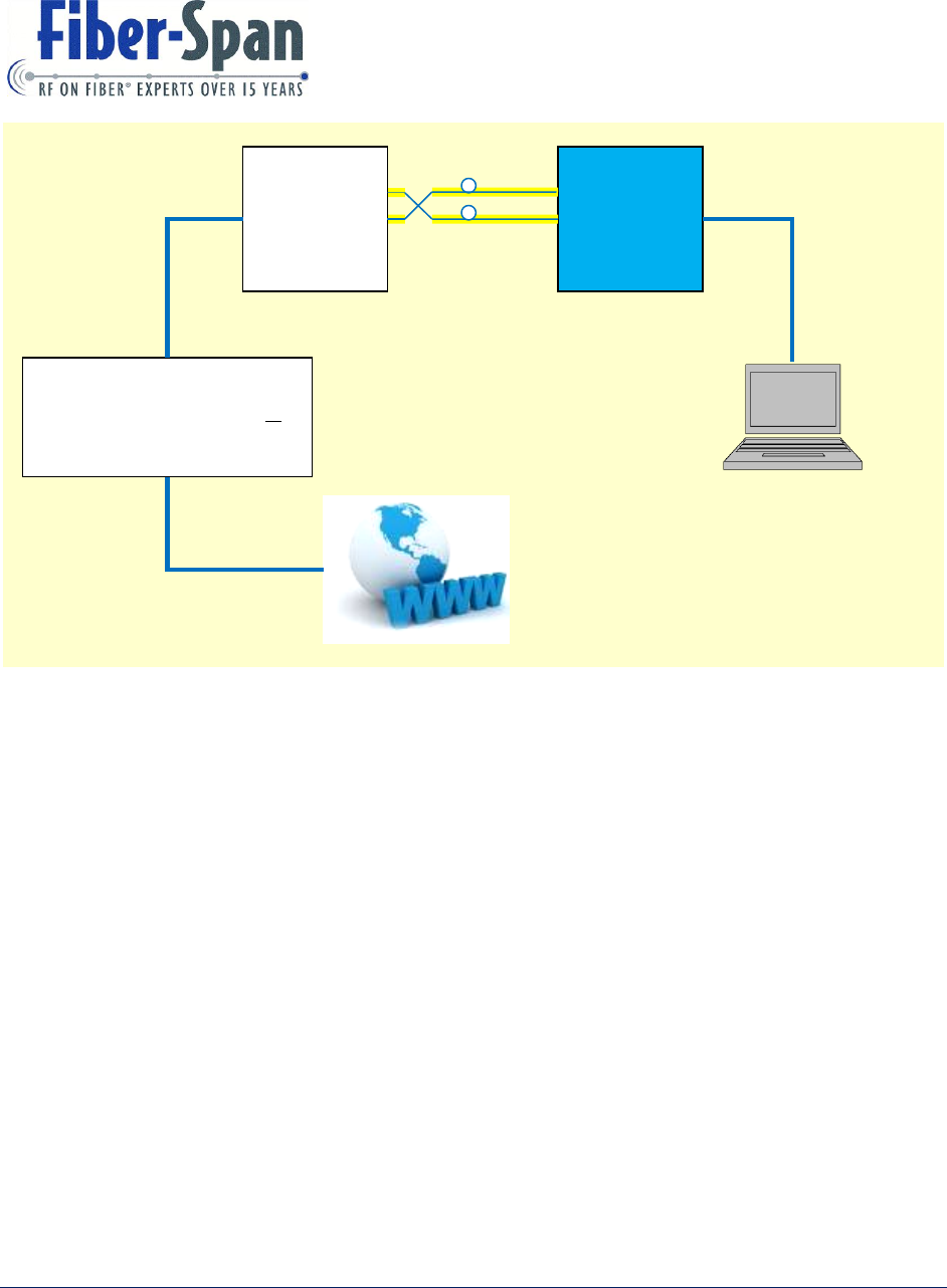
Appendix A FS31R-15C RRU Media Converter
This section calls out the hardware needed and explains how to connect the media converter
section of the Remote Repeater Unit (RRU) for approving its functionality.
Hardware Needed
1. One media converter (for use as reference) including its power supply.
2. One SFP module.
3. Two 9/125 um single mode fibers SC/APC-to-LC/PC (1 meter length).
4. Three Ethernet cables (RJ45 connectors).
5. One PC or Laptop.
How to connect:
1. Before applying power, connect all three Ethernet cables;
a. Connect Cable 1 from PC to RRU USB port.
b. Connect Cable 2 from reference media converter to Switch.
c. Connect Cable 3 from Switch to Local Area Network (LAN).
2. Using two single mode fiber patch cable (~1 meter length), connect the fiber cable end to
RRU optical out port and the other cable end to the media converter input. Connect the
other fiber cable to the RRU optical in port and the other cable end connect it to the
media converter output.
3. Always terminate RRU RF port with a 50 Ohm Load.
4. Apply power to the media converter and the RRU.
A-2 3434 Rt. 22W ▪ Suite 140 Branchburg, NJ 08876
908.253.9080 ▪ fiber-span.com
Turn on the PC and open an internet browser. Using a search engine like Google, check on the
internet for the today’s news. If you are able to do so, the media converter section is functioning
properly.
With this step the fiber medium has been proving to work at 0dBo, now replace both fiber cables
with two 10 dBo single mode fiber patch cables and retest.
Troubleshooting Tip
The optical transceivers in-use has a high sensitivity margin that operates from 0 to 10 dBo
optical loss this is not expected to be an issue. Upon encountering an issue, check that the fiber
cables are not kinked or bend excessively. If issue continues, unplug every optical connector and
Reference
180-0113
Media
Converter
FS31R-15C
RRU
(DUT)
Dell Power Connect 16-Port
Gigabit Ethernet ‘Switch’ or
Equivalent
2- Single
Mode Fiber
Ethernet
Cable
>> Using PC open and access WEB
Ethernet
Cable
Ethernet
Cable
LAN
Figure 11: RRU Media Converter Test Setup Block Diagram

A-3 3434 Rt. 22W ▪ Suite 140 Branchburg, NJ 08876
908.253.9080 ▪ fiber-span.com
re-clean tip with isopropyl alcohol until the internet is accessible. Another problem can be that
the fiber cables are incorrectly crossover.
The fiber path of the RRU transmitter side connects to the Receiver side on the reference media
converter and the fiber path of the RRU receiver side connects to the transmitter side of the
reference media converter.