Fiber Span FS31X-85-C FIBER OPTIC CONNECTED RF AMPLIFIER User Manual USERS MANUAL
Fiber-Span LLC FIBER OPTIC CONNECTED RF AMPLIFIER USERS MANUAL
USERS MANUAL

Page 1 of 12 Rev 02 11-Jul-05 FS31LX-XX and FS31X-85-C
Fiber Optic RF Repeater System
Fiber-Span
Installation Guide and User Manual
FS31LX-XX and FS31X-85-C
Fiber Optic RF Repeater System
This devices complies with part 15 of the FCC Rules. Operation is subject
to the following two conditions: (1) This device may not cause harmful
interference, and (2) this device must accept any interference received,
including interference that may cause undesired operation.
Part 15.21
Changes or modifications not expressly approved by the party responsible
for the compliance could void the user’s authority to operate the
equipment.
NOTE: The manufacturer is not responsible for any radio or TV
interference caused by unauthorized modifications to this equipment.
Such modifications could void the user’s authority to operate the
equipment.

Page 2 of 12 Rev 02 11-Jul-05 FS31LX-XX and FS31X-85-C
Fiber Optic RF Repeater System
Fiber-Span ..........................................................................................................................1
Installation Guide and User Manual .................................................................................1
FS31LM-01-LMC and FS31HM-85-C-18-65 ........................................................................1
Fiber Optic RF Repeater System .........................................................................................1
1 Introduction ...................................................................................................................2
2 Warnings.......................................................................................................................2
Warning: Invisible radiation exits from areas labeled “Aperture” .........................................2
3 Product overview ..........................................................................................................3
4 Connection Diagrams ...................................................................................................3
5 Installation Procedure ...................................................................................................4
5.1 General..................................................................................................................4
5.2 FS31LM-01-LMC, Fiber Transceiver Unit (FTU)....................................................4
5.3 FS31HM-85-C-18-65, Optical Repeater Unit (ORU)..............................................5
6 System Equipment Setup Downlink ..............................................................................7
7 System Equipment Setup Uplink...................................................................................8
7.1 Calibration Procedure ............................................................................................9
7.2 Downlink Results .................................................................................................11
7.3 Uplink Results......................................................................................................11
7.4 Caution ................................................................................................................11
8 Maintenance ...............................................................................................................11
9 Company Information..................................................................................................11
10 Reference Documents.............................................................................................12
1 Introduction
This high performance Analog RF Fiber Optic Transmission Repeater System
converts RF signals into intensity modulated light to be carried through standard
single mode optical fiber to an Optical Receiver. The Receiver converts the
modulated light back to the original RF signal. Fiber-Span uses high performance
optical components and patented technology to ensure maximum dynamic range.
2 Warnings
Warning: Invisible radiation exits from areas labeled “Aperture”
AC power is used to supply power up the system modules. Use precautions to
prevent electrical shock hazards. Always terminate the RF connections before
applying power to the unit.
Page 3 of 12 Rev 02 11-Jul-05 FS31LX-XX and FS31X-85-C
Fiber Optic RF Repeater System
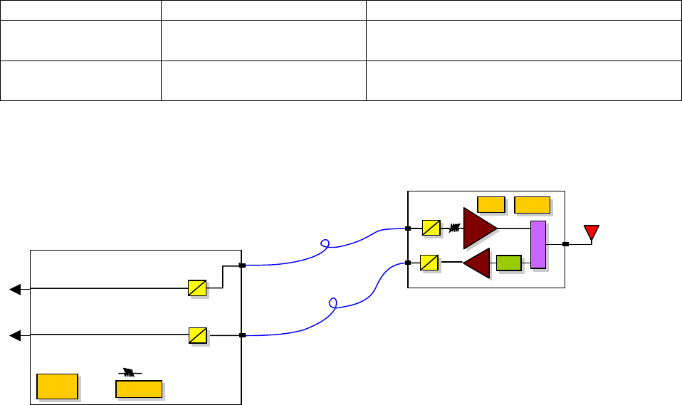
Optical Repeater Unit (ORU)
eo
P
A
eE
MGC
Du
ple
xe
r
LN
P.S.
A
larms
P
A
e
o
Power
Supply Alarms
e
o
OE
O
E
Fiber Optic
Cables
Fiber Transceiver Unit (FTU)
3 Product overview
The fiber optic repeater system is designed to transport and distribute Public Safety
& Private Land-Mobile Radio Frequencies signals through fiber optic medium. The
Downlink has high Power to drive Distributed Antenna Systems (DAS). The Uplink
has Low Noise figure to receive low signals over the air antenna.
The purpose for this system is to expand radio coverage for an In-Building System
which is between the 806-824 MHz Uplink and 851-869 MHz MHz Downlink range.
This is done by sending and receiving the RF signals from the basestation and
distributing the radio signals over fiber, to a remote fiber optic transceiver to
interface to a remote antenna. The system design is for single or up to 32 remote
optical repeaters.
The FS31LM-01-LMC is a subrack fiber optic transceiver, which can contain from
one to four transceivers. These transceivers provide the optical connections to the
FS31HM-85-C-18-65 Remote Repeater. The FS31LM-01-LMC is AC powered and
offers transceiver alarm LED indicators, Dry contact (NO) alarm terminals, and RF
gain control for each receiver for uplink signals.
The FS31HM-85-C-18-65 interfaces with the fibers from the FS31LM-01-LMC and
connects the remote antenna to a single RF port. The FS31HM-85-C-18-65 is AC
powered and offers Dry contact (NO) alarm terminals for the transceiver, door open,
and PA alarms.
System Components and Descriptions
Model Function Description
FS31HM-85-C-18-
65
Optical Repeater Unit Transmitter and Receiver Amplifier
Single RF, Dual Optical Port
FS31LM-01-LMC Fiber Transceiver Unit Transmitter and Receiver Dual RF
Port, Dual Optical Port
4 Connection Diagrams
To Base-
station Uni
t
Page 4 of 12 Rev 02 11-Jul-05 FS31LX-XX and FS31X-85-C
Fiber Optic RF Repeater System
5 Installation Procedure
5.1 General
All unused RF Terminals must be terminated with a 50 Ohm load. All unused Optical
Terminals must be protected using dust cover cap. When installing fiber optic cables,
remove dust covers, clean optical connector with optical grade alcohol, align FC/APC
connector KEY and hand tighten. Do not over tighten.
5.2 FS31LM-01-LMC, Fiber Transceiver Unit (FTU)
Figure 1. FS31LM-01-LMC Single Fiber Transceiver Unit
The FS31LM-01-LMC Fiber Transceiver Unit (FTU) is a 19” standard 1U subrack.
The FTU requires AC Power (90 to 220 VAC, 50-60 Hz). The AC interface is a
standard IEC Power socket. A US 120V AC Line Cord is supplied with each FTU.
Mount Fiber Transceiver Unit in close proximity to the BSU interfaces to minimize
cable lengths.
Make all RF connections and terminate all unused RF connections before applying
AC Power.
Interface for U
p
link Receiver 1 Interface for Downlink Transmitter 1 Main Power Indicato
r
RF OUT Optical
Input
RX manual
gain control
RF INPUT
TX
Optical
Output
Received LED
Optical Power
RX Dry Contact
Relay Normally
Open
TX Dry
Contact
Relay
Normally
Open
TX LED
Overcurrent
Indicator
Power LED
Indicator

Page 5 of 12 Rev 02 11-Jul-05 FS31LX-XX and FS31X-85-C
Fiber Optic RF Repeater System
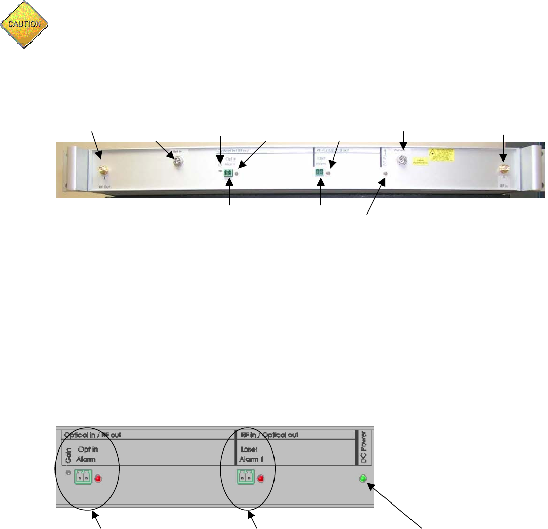
Figure 2. Fiber Transceiver Unit User Alarms and Control Interface (FS31LM-01-
LMC)
The user alarms and controls are organized by link type. The Optical in / RF out section is
for the uplink optical receivers and the RF in / Optical out section if for the downlink optical
transmitters. For uplink optical receivers, each receiver has a gain control that is accessed
using a small standard screwdriver.
The Opt in Alarm interface uses a wire contact header (supplied) that will plug into
the Opt in Alarm sockets. Connection of alarm wires to the wire contact header
requires a small standard flathead screwdriver. The Optical In alarm LED on the
right side of the alarm header indicates an alarm condition for each individual uplink
optical receiver.
For Downlink optical transmitters, each Opt in Alarm interface uses a wire contact
header (supplied) that will plug into the Opt in Alarm sockets. Connection of alarm
wires to the wire contact header requires a small standard screwdriver. The alarm
LED on the right side of the alarm header indicates an alarm condition for each
individual downlink optical transmitter.
Connect fiber optic cables last. Use fiber optic connector cleaning precautions to
get the highest performance from the system. Do not make optical connector tip
contact with any hard surface. Be sure the FC/APC KEY is aligned before
tightening. Do not over tighten.
5.3 FS31HM-85-C-18-65, Optical Repeater Unit (ORU)
Also known as BDA.
Below is a diagram of the inside of the ORU.
Page 6 of 12 Rev 02 11-Jul-05 FS31LX-XX and FS31X-85-C
Fiber Optic RF Repeater System
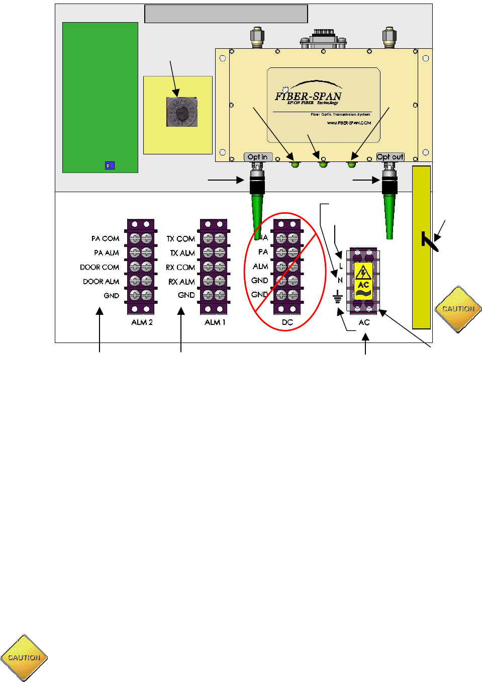
Figure 3. ORU Interface Internal View.
The BDA enclosure is IP65 rated for outdoor use. The BDA is to be mounted
ONLY IN UPRIGHT POSITION (See Figure 4). When installing cable conduits, use
standard practices to keep enclosure weatherproof. The BDA requires AC Power
(90 to 220 VAC, 50-60 Hz). The AC interface requires the power wires to have a
standard ¼” fork terminal termination for HOT (H), Neutral (N), and Ground
connections. Connect BDA to earth ground using Earth Ground Lug on the
external side of BDA. Power amplifier Automatic Level Control (ALC) switch must
be in Auto Mode.
Make all RF connections and terminate all unused RF connections before applying
AC Power.
The Alarm interface requires the wire connections to have a standard ¼” fork
terminal terminations. Connect terminals as indicated in figure 5. Do not over
tighten terminals.
A
C Power
Protection
Cover
Line
DO NOT CONNECT !
DC Terminals used for
Internal Connections only
Connect Alarm
Terminals on
Left Side
Connect Alarm
Terminals on
Left Side
Sensitivity
A
djustment
Alarm and
Control
PCB
Downlink Optical
Connection Uplink Optical
Connection
Power
LED
TX
A
larm
LED
RX
Alarm
LED
Ground
Neutral
A
C-DC POWER SUPPLY
P
O
W
E
R
A
M
P
A
C Powe
r
Connections
LNA
A
LC SWITCH
POSITION
A
UTO,
TOWARDS
BOTTOM OF
ORU
Page 7 of 12 Rev 02 11-Jul-05 FS31LX-XX and FS31X-85-C
Fiber Optic RF Repeater System
Remove AC Power Protection Cover, loosen screw terminal to allow fork terminal
connection. Connect the corresponding Hot, Neutral, and Ground connections. Do
not over tighten terminals. Replace AC Power Protection Cover for safety.
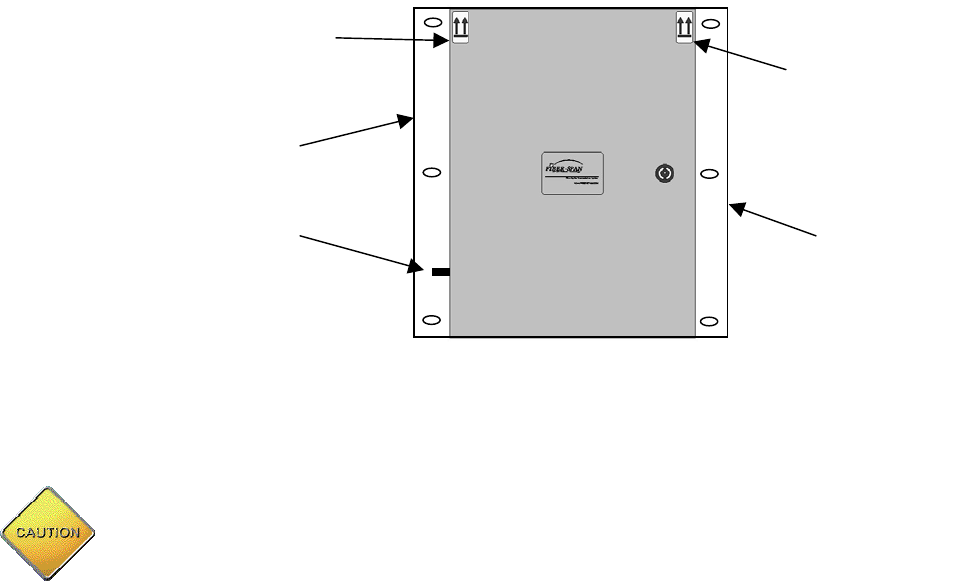
Figure 4. Upright Mounting View.
Connect fiber optic cables last. Use fiber optic connector cleaning precautions to
get the highest performance from the system. Do not make optical connector tip
contact with any hard surface. Be sure the FC/APC KEY is aligned before
tightening. Do not over tighten.
The Downlink Output level adjust is factory set to meet the typical RF output level.
The system is optimize to absorb optical loss via the medium.
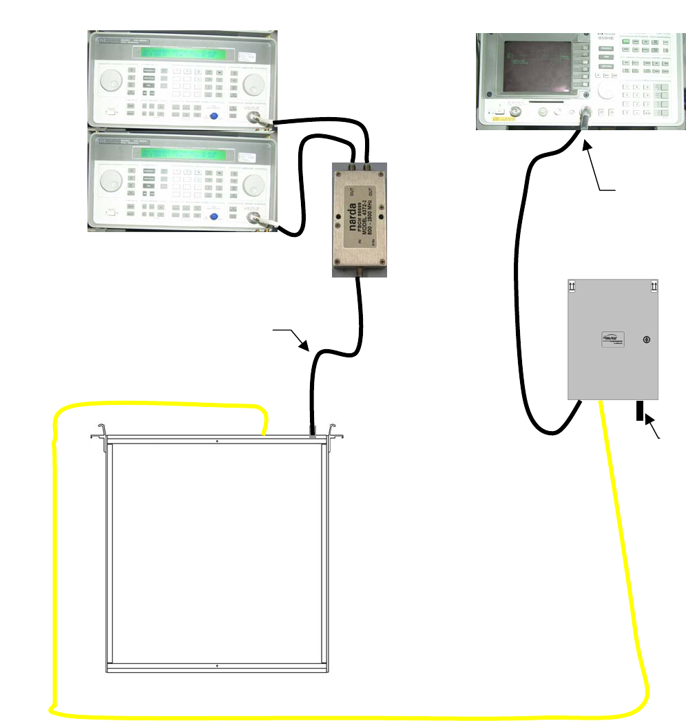
6 System Equipment Setup Downlink
This End
Up
This End
Up
Earth
Ground
Lug
Mounting
Bracket
Mounting
Bracket
Page 8 of 12 Rev 02 11-Jul-05 FS31LX-XX and FS31X-85-C
Fiber Optic RF Repeater System
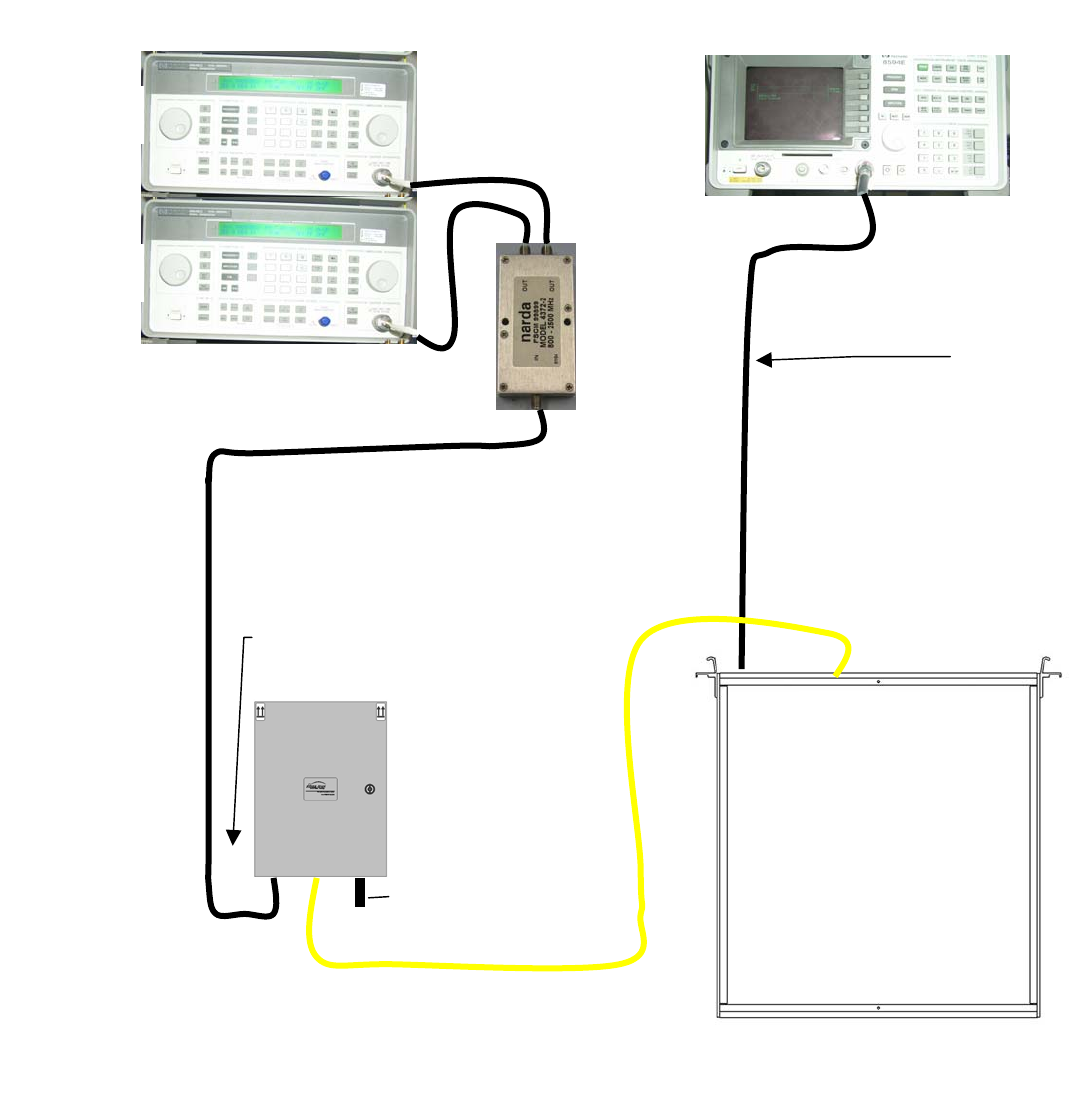
7 System Equipment Setup Uplink
RF Downlink Levels
2 Tones Start @-16.0 dBm
Composite, increase level in 2 dB
Steps to a maximum of 0 dBm
Com
p
osite
AC CORD
ORU
RF Downlink Outpu
t
+31 dBm Composite
Automatic Level Activates
After +31 dBm
Fiber Patch
Cord
FTU Fiber
Transceiver
Unit
RFINOptical
Out
Optical
In
RF
OUT
Generator
Generator
Spectrum Analyzer
Splitter
Page 9 of 12 Rev 02 11-Jul-05 FS31LX-XX and FS31X-85-C
Fiber Optic RF Repeater System
7.1 Calibration Procedure
7.1.1 Equipment Requirements
• RF Spectrum Analyzer capable of Marker Noise per Hz measurements in 800 to
900 MHz band and power measurements up to +30 dBm. (Equivalent Model is HP
8594E)
• Low Noise Pre-Amplifier 806 to 869 MHz Band pass with 20 to 30 dB Gain and
Noise figure less than 10 dB. (Equivalent Model is Agilent 8447D, 25dB, 8.5 dB
NF)
RF Uplink Levels
2 Tones @ -40 dBm
Composite
AC CORD
ORU
RF Uplink
Level Output
-13 dBm
Fiber Patch
Cord
FTU Fiber Transceiver Unit
Optical
Out
RF
In
Optical
In
RF
OUT
Generator
Generator
Splitter
Spectrum Analyzer
Page 10 of 12 Rev 02 11-Jul-05 FS31LX-XX and FS31X-85-C
Fiber Optic RF Repeater System
• RF cables and adapters as required
• Small Screwdriver Flathead
• Optical grade cleaning alcohol (99.6% pure)
• Fiber Optic Connector Cleaner
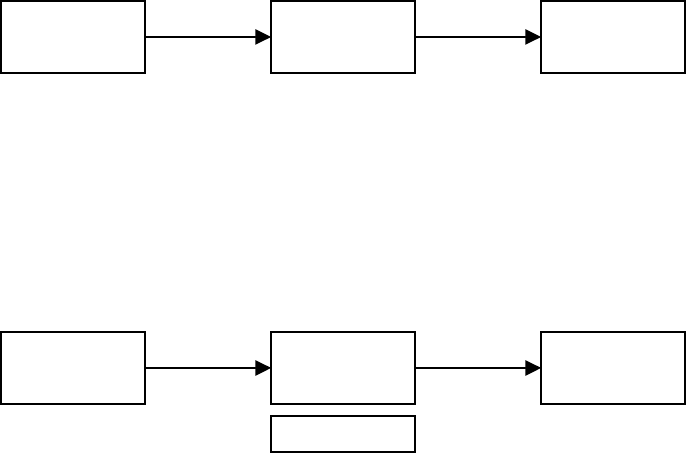
7.1.2 Measurement Setup Diagrams
Figure 5. RF Signal Measurements
Attenuator is for high power RF measurements. The attenuator is not required for
low power measurements ( about 0 dBm RF Levels). For high RF power
measurements, use a 10 dB, 2 Watt attenuator pad when maximum RF level into
Spectrum Analyzer is at +30 dBm, set the analyzer input attenuator set to 50 dB.
Figure 6. RF Noise Measurements
RF Amplifier is for low power RF Noise measurements. Analyzer input attenuator
set to 0 dB. Spectrum Analyzer is set for marker noise mode to give noise per Hz
display. The marker must be positioned on the noise floor and not on any spurious
signals in the RF frequency band. Noise of RF source is analyzer noise
measurement is:
GNsaRFnoise −= (dBm/Hz) eq.1
Where, RFnoise is the RF Source noise in dBm/Hz, Nsa is noise measured on the
spectrum analyzer in dBm/Hz, and G is the amplifier Gain in dB. Using the gain
control of the FTU front panel potentiometer adjusts noise level to be compatible
with the basestation requirements. LNA has uplink sensitivity level capability.
RF
Source
Spectrum
Analyzer
Attenuator
RF
Source
Spectrum
Analyzer
RF
Amplifier
Gain = G
(
dB
)

Page 11 of 12 Rev 02 11-Jul-05 FS31LX-XX and FS31X-85-C
Fiber Optic RF Repeater System
7.1.3 Start up Conditions
• Verify all RF cables are connected and all unused RF connections terminated with
50 Ohm terminations.
• Verify all Alarm and AC connections are properly made
• Apply AC power to system components.
• Connect fiber optic cables.
• Use fiber optic connector cleaning precautions to get the highest performance from
the system. Do not make optical connector tip contact with any hard surface. Be
sure the FC/APC key is aligned before tightening. Do not over tighten.
Do Not exceed the Maximum Rf input level to units, FTU downlink is RF input 0
dBm Composite. ORU Uplink RF input is (-) 40 dBm Composite.
7.2 Downlink Results
The ORU has high output power and provides 1.26 Watts of RF Power (+31 dBm).
The ORU has constant automatic level when the output reaches 31 dBm
Composite. See Heading 6 for equipment setup. Inside the ORU the rf gain is
factory adjust with a potentiometer and does not need to be adjusted.
7.3 Uplink Results
The Uplink rf gain is set to 27 dB with a 1 meter fiber patch cord. See Heading 7 for
equipment setup. The noise figure is 4dB. Use the test configuration shown in part
7. Connect the spectrum analyzer to the RF out port corresponding to the
transceiver being calibrated. Adjust the gain on the front panel of the Fiber
Transceiver Unit (FTU) for the transceiver being calibrated to give an RF level
required at the basestation.
7.4 Caution
BDA has internal AC power connections that can cause shock if operator is not
careful. Always verify the AC Power Protection Cover is protecting the AC line
connections on the terminal block connector. Do not leave tools inside of BDA that
can cause dangerous shock hazard.
8 Maintenance
This Fiber Optic repeater system does not require maintenance. However, use
precautions while installing optical fibers to keep connector surfaces clean. An
unclean optical connector surface can damage the internal transceiver connector
which will degrade system performance and void Fiber-Span warranty.
9 Company Information

Page 12 of 12 Rev 02 11-Jul-05 FS31LX-XX and FS31X-85-C
Fiber Optic RF Repeater System
Fiber-Span designs and manufactures fiber optic modules and systems used in the
transmission and distribution of RF and wireless signals. Fiber-Span’s fiber optic
transmitters, receivers and transceivers are widely used in wireless and RF systems
worldwide by wireless systems OEM’s, systems integrators and military systems
designers to capitalize on the inherent advantages of fiber. Fiber has extremely low
RF attenuation (< 1dB/km), very high bandwidth, immunity to EMI, no signal egress,
flat broadband delay characteristics plus a cable design that is light weight and
small size.
Fiber-Span
111 Corporate Blvd.
South Plainfield, NJ 07080
USA
908-754-0646
908-754-0647 FAX
Internet
http://www.fiber-span.com
techinfo@fiber-span.com
10 Reference Documents
Document Title Document Description
7109-0705-OUT FS31HM-85-C-18-65
ORU Optical Repeater Unit
7109-0713-OUT FS31LM-01-LMC
FTU Fiber Transceiver Unit