Fiber Span FS42R-IDEN-2 Repeater; Plug-in Service Module, 800/900 MHz iDen User Manual
Fiber-Span LLC Repeater; Plug-in Service Module, 800/900 MHz iDen
User Manual
UserManual
RemoteFiberNode(RFN)
Multi‐serviceruggedizedequipmentextends carrierservices

Remote Fiber Node (RFN) User Manual
©Copyright 2011, Fiber-Span Page 2 of 38
1. Limitation of Liability
Copyright 2011 Fiber-Span. All rights reserved. No part of this publication, or any software included with it
may be reproduced, stored in a retrieval system, or transmitted in any form or by any means, including
photocopying, electronic, mechanical, recording or otherwise, without the prior written permission of the
copyright holder.
Fiber-Span provides this document as is, without any warranty of any kind either expressed or implied including,
but not limited to, the implied warranties of merchantability and fitness of a particular purpose. Fiber-Span may
make changes or improvements in the equipment, software, or specifications described in this document at any
time and without notice. These changes will be incorporated in new releases of this document.
This document may contain technical inaccuracies or typographical errors. Fiber-Span waives responsibility for
any labor, materials, or costs incurred by any person or party as a result of using this document. Fiber-Span and
any of its affiliates shall not be liable for any damages (including, but not limited to, consequential, indirect or
incidental, special damages or loss of profits or date) even if they were foreseeable and Fiber-Span has been
informed of their potential occurrence, arising out of or in connection with this document or its use.
Fiber-Span
3434 Route 22 W.
Branchburg, New Jersey
08876
Tel: (908) 253-9080
Fax: (908) 253-9086
www.fiber-span.com

Remote Fiber Node (RFN) User Manual
©Copyright 2011, Fiber-Span Page 3 of 38
2. Introduction
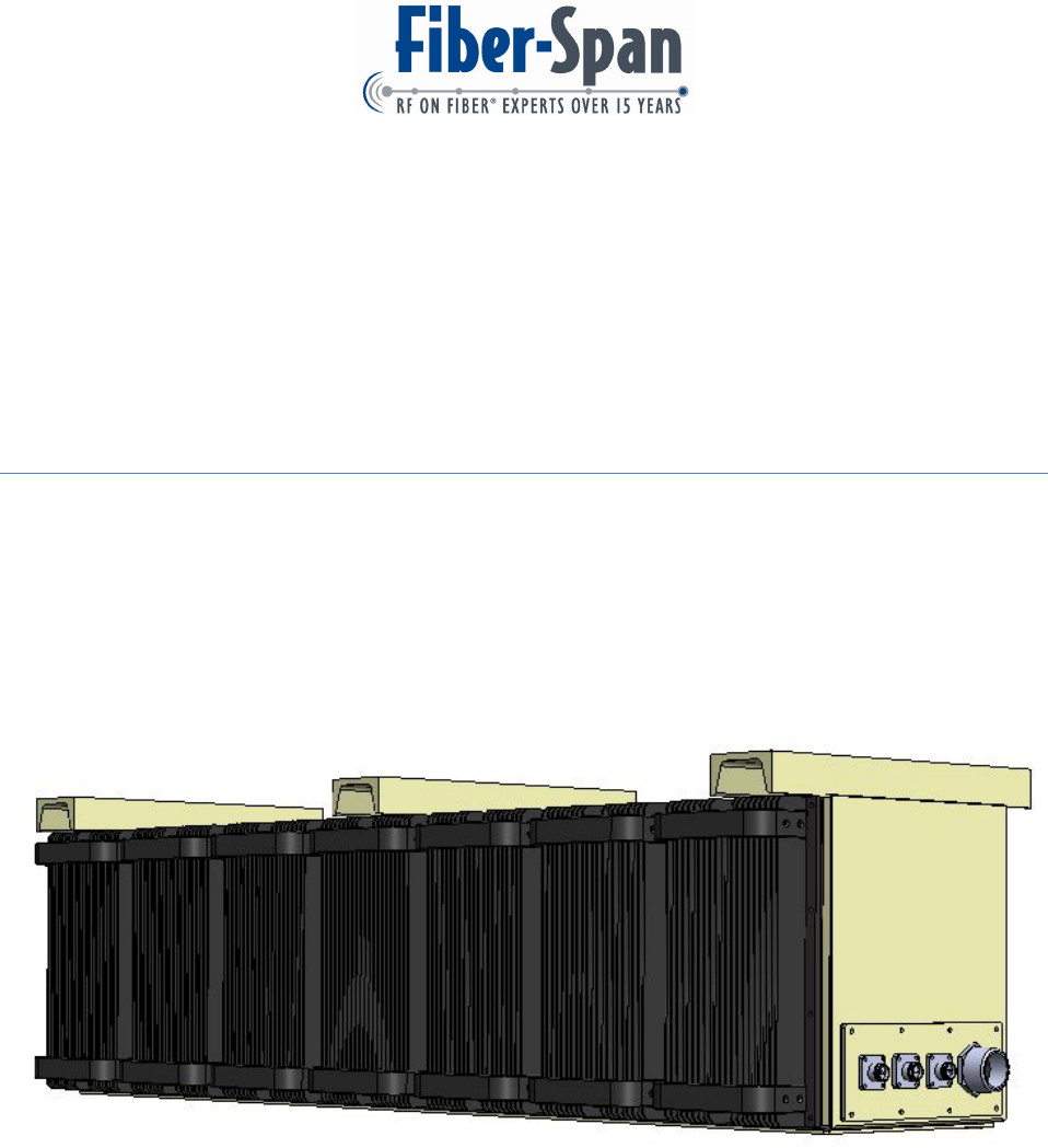
The FS47 Remote Fiber Node (RFN) is a multi-service equipment designed to extend multiple
wireless carrier services such as 700, 800/900 iDEN, Cellular, PCS, AWS, WiFi and WiMAX.
The RFN’s unique design allows it to be easily adapted to meet the demands of new
generations of communication schemes.
All three DAS interface ports are capable of providing a high linear output power greater than
25 dBm per band.
Incorporating a unique feature, the system provides three downlink/ uplink RF ports for
connection to distributed antenna systems (DAS) capturing distributing and launching, the
many frequency bands at once using Dense Wavelength Division Multiplex (DWDM)
technology allowing simultaneous extended wireless coverage from many of the carrier services.
The RFN utilizes a rugged enclosure to withstand high vibration, and the front façade of each
plug-in module has a large heat sink for efficient heat dissipation. The RFN employs modular
construction, offering trouble-free access to individual carrier services for maintenance and
upgrade, without disrupting the operation of any of the others.

Remote Fiber Node (RFN) User Manual
©Copyright 2011, Fiber-Span Page 4 of 38
3. Revision History
VersionDescriptionDateAuthor
0.1Draftrelease8‐Mar‐2011C.M.

Remote Fiber Node (RFN) User Manual
©Copyright 2011, Fiber-Span Page 5 of 38
4. Table of Contents
1.Limitation of Liability ............................................................................................................. 2
2.Introduction ............................................................................................................................. 3
3.Revision History ..................................................................................................................... 4
4.Table of Contents .................................................................................................................... 5
5.Warnings ................................................................................................................................. 7
6.Product Overview ................................................................................................................... 8
6.1.WiFi .................................................................................................................................. 9
6.2.iDEN................................................................................................................................. 9
6.3.AWS ............................................................................................................................... 10
6.4.700 .................................................................................................................................. 11
6.5.Cellular ........................................................................................................................... 12
6.6.Extended PCS ................................................................................................................. 12
7.Block Diagram ...................................................................................................................... 13
7.1.RFN Block diagram ....................................................................................................... 13
7.2.Plug-in ............................................................................................................................ 14
7.3.System Block Diagram................................................................................................... 14
7.4.Optics ............................................................................................................................. 15
8.General .................................................................................................................................. 19
8.1.RF ................................................................................................................................... 19
8.2.Optical ............................................................................................................................ 19
8.3.Alarm Monitor and Control Software ............................................................................ 21
8.3.1.PC Requirements .................................................................................................... 21
8.3.2.Launch Program ...................................................................................................... 21
8.3.3.Firmware Revision .................................................................................................. 21
8.3.4.General Settings ...................................................................................................... 21
8.3.5.Username / Password .............................................................................................. 21
8.3.6.Default and Status Settings ..................................................................................... 21
8.3.7.Block Diagram ........................................................................................................ 21
8.3.8.Controls ................................................................................................................... 21
8.3.9.Alarm Settings ........................................................................................................ 21
8.3.10.Software Windows .............................................................................................. 21
8.3.11.Alarms and Controls............................................................................................ 21
8.4.Connector Type .............................................................................................................. 21
8.5.Mechanical ..................................................................................................................... 21
8.6.Switches & Indicators .................................................................................................... 21
9.Installation............................................................................................................................. 22
9.1.Mounting ........................................................................................................................ 22
9.2.Optical Connections ....................................................................................................... 22
9.3.Tools ............................................................................................................................... 24
9.4.Grounding....................................................................................................................... 24
10.General Precautions ........................................................................................................... 25
11.Startup Checklist ................................................................................................................ 26
11.1.Equipment List ........................................................................................................... 26
11.2.On Site Requirements ................................................................................................. 26

Remote Fiber Node (RFN) User Manual
©Copyright 2011, Fiber-Span Page 6 of 38
12.Maintenance ....................................................................................................................... 27
12.1.Periodic Inspection Checklist ..................................................................................... 27
12.2.Preventative Measure for Optimal Operation ............................................................. 27
12.2.1.Optical Maintenance ........................................................................................... 27
12.2.2.RF ........................................................................................................................ 27
13.Factory Settings ................................................................................................................. 28
14.Specifications ..................................................................................................................... 29
14.1.Electrical Specifications ............................................................................................. 29
14.1.1.FS47R .................................................................................................................. 29
14.1.2.Plug-in ................................................................................................................. 29
14.2.Mechanical Specifications .......................................................................................... 30
14.2.1.Chassis ................................................................................................................. 30
14.2.2.Plug-in ................................................................................................................. 30
14.3.Other Specifications ................................................................................................... 30
15.Outline Drawing................................................................................................................. 31
16.Illustrations ........................................................................................................................ 32
16.1.Internal ........................................................................................................................ 32
16.2.External ....................................................................................................................... 32
16.3.Plug-in DC .................................................................................................................. 32
17.Troubleshooting ................................................................................................................. 33
17.1.RF ............................................................................................................................... 33
17.2.Optics .......................................................................................................................... 33
17.3.Ethernet ....................................................................................................................... 33
18.Warranty ............................................................................................................................ 34
18.1.General Warranty ....................................................................................................... 34
18.2.Limitations of Warranty ............................................................................................. 34
18.3.Limitations of Damages.............................................................................................. 34
18.4.Return Material Authorization (RMA) ....................................................................... 34
19.FCC Required Statement ................................................................................................... 35
20.Glossary ............................................................................................................................. 36
21.Reference Documents ........................................................................................................ 37
22.Company Information ........................................................................................................ 38
Remote Fiber Node (RFN) User Manual
©Copyright 2011, Fiber-Span Page 7 of 38
5. Warnings
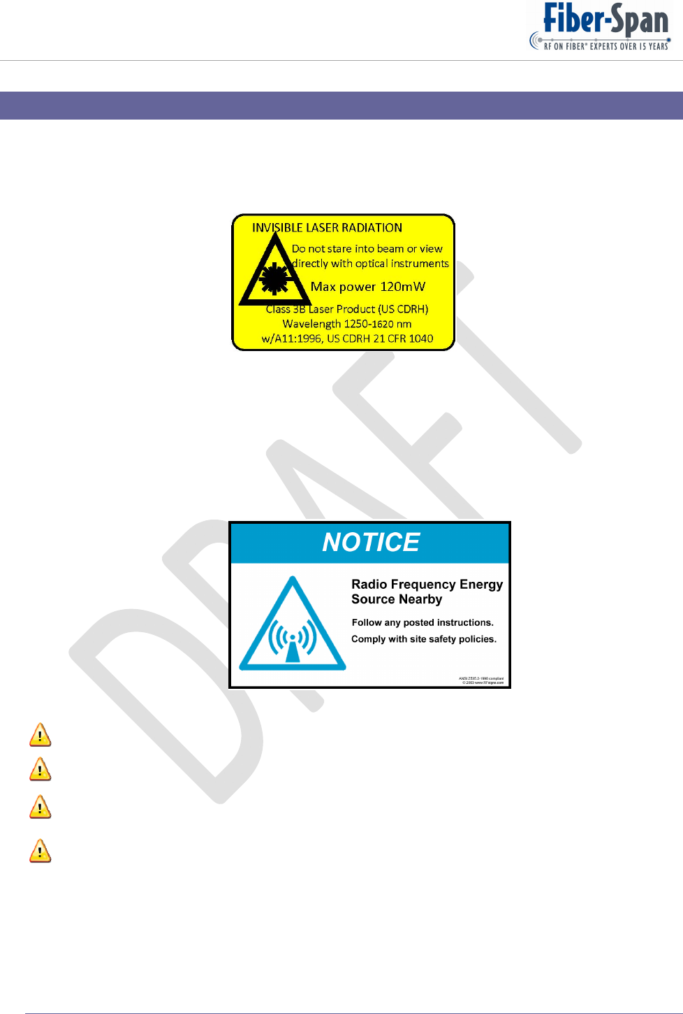
Invisible radiation exits from areas labeled “Aperture”
All fibers at both ends of the optical link connected before applying power to either fiber
transceiver unit and remote fiber node will prevent exposure.
Follow and comply with all site safety policies.
Exclamation point denotes attention to statement.
Terminate all RF ports with a 50 Ohm load.
While in operation do not touch RFN front façade heat sink because surface is very HOT.
Maximum RF Input level -30 dBm.
Only a qualified technician shall be allowed to operate the unit, after reading and understanding
all the guidelines in this manual.
Remote Fiber Node (RFN) User Manual
©Copyright 2011, Fiber-Span Page 8 of 38
6. Product Overview
A Remote Fiber Node (RFN) chassis has 7 compartments that houses a variety of modular plug-in
modules, of which their internal components and rear-mount mechanisms are mapped according to
operating frequency bands. Chassis inside slots have a mating rear receptacle that provides primary
power to the plug-ins as well as the RF Input / Output interface functions.
There is no optical interface between any of the plug-ins and the back receptacle.
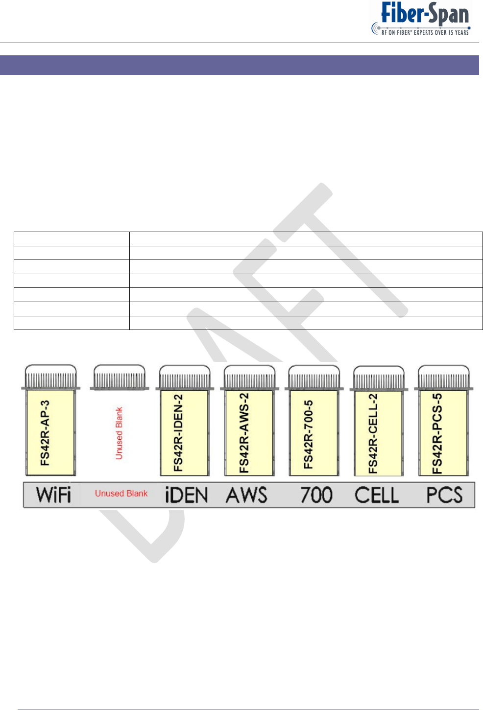
As viewed with heat sink facing you, (from left-to-right) each chassis slot is dedicated to a frequency
band; a list of which is shown in Figure 1 below:
Slot 1 WiFi 2.4 GHz
Slot 2 Unused, but accommodates WiMAX
Slot 3 iDEN 800/900 MHz
Slot 4 AWS 2.1 GHz
Slot 5 700 MHz
Slot 6 Cell 850 MHz
Slot 7 PCS 1.9 GHz
Figure 1
Figure 2: Frequency Band Layout
Internally, the Plug-ins employ similar circuitry and layout designs using filters, attenuators, low
noise amps and power amplifiers for their respective allocated frequency band, excluding the WiFi
Plug-in.
For future upgrade purposes, the factory may re-position frequency band plug-ins slots from that
shown here.
All the plug-ins are HOT-swappable which allows removal and replacement while the RFN is ON
and operating.
Remote Fiber Node (RFN) User Manual
©Copyright 2011, Fiber-Span Page 9 of 38
6.1. WiFi
WiFi is short for “Wireless Fidelity”, and uses IEEE 802.11 specifications with protocols for
communicating end-to-end via a wireless network.
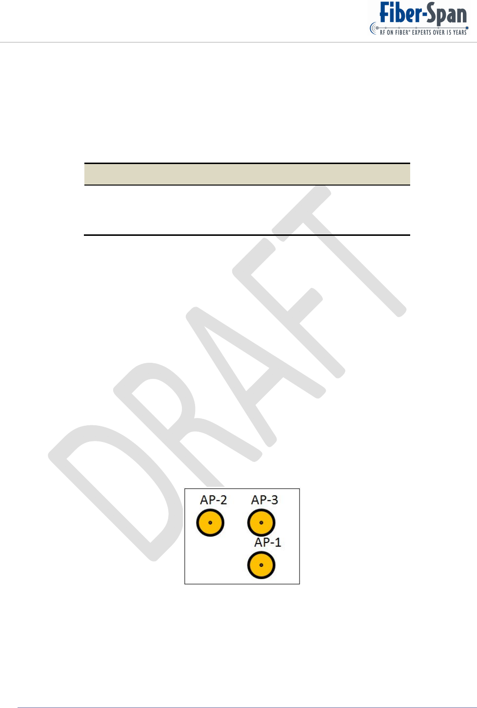
The WiFi Plug-in has 3 access points each one independently going to antenna 1,2 and 3 with
the Channel set to:
Access‐PointPositionAntennaIDChannelName
LeftANT1WiFiChannel1
CenterANT2WiFiChannel6
RightANT3WiFiChannel11
For 802.11g operation, typical receive sensitivity ranges from -73 dBm at 54 Mbps to -96 dBm
at 1 Mbps. For all practical purposes, as Mbps data rate doubles sensitivity drops by 3 dB.
Indoor wireless coverage ranges from 460 ft. at 1 Mbps to 105 ft. at 54 Mbps data rate.
Outdoor use (compared to indoor) with no obstruction distance doubles between 1- 48 Mbps,
but not much higher of 120 ft. at 54 Mbps.
Measurements were taken with a 2.2-dBi dipole antenna for 2.4 GHz.
Maximum power draw per access point is 12.95 Watts x 3 equals 38.85 Watts Total.
For added isolation access point ports have an in-line band pass filter. Instrument operates in
the 2400-2483.5 MHz region.
Figure 3 displays Plug-in WiFi RF connections in rear.
Figure 3
6.2. iDEN
The iDEN Plug-in is a bi-directional service module comprising of uplink and downlink
circuitry. Internally it houses all the devices that condition, filter and amplify the specified
frequency band while rejecting the adjacent family bands operating within the chassis.
Remote Fiber Node (RFN) User Manual
©Copyright 2011, Fiber-Span Page 10 of 38
Although it accommodates both paths, circuitry is kept shielded providing 120 dB of isolation
between them which prevents any RF crosstalk.
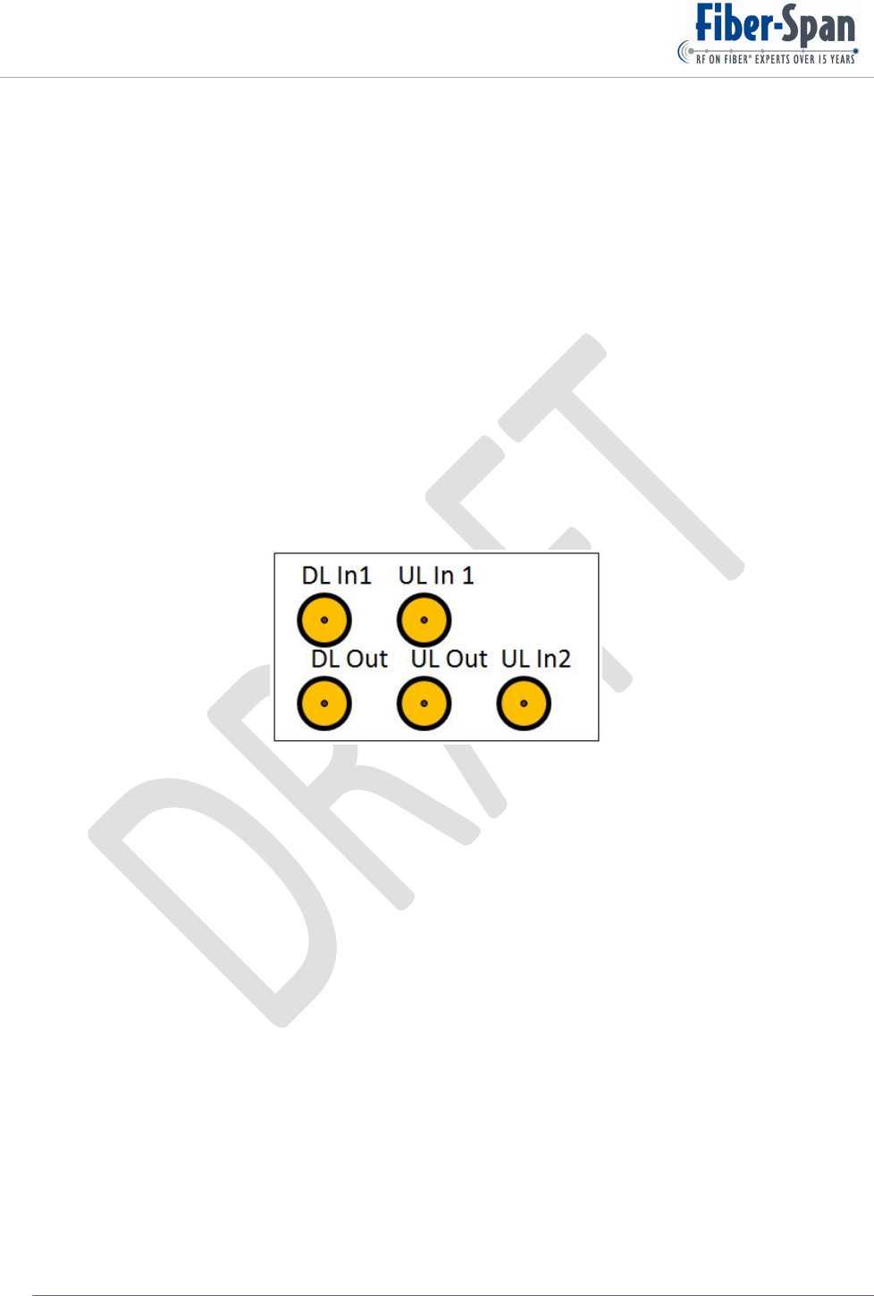
The iDEN uplink has 2 independent internal inputs that combined iDEN 8 and iDEN 9
allocated bands. Downlink last stage output power amplifier accommodates both iDEN 8 and
iDEN 9 frequency bands.
Circuitry is similar in the UL and DL paths, with uplink RF Gain at 40 dB while the downlink
has more gain, with the addition of a high power amplifier module that provides 40 dB to drive
the DAS for a total of 70 dB from end to end. In both directions, inserted between the pre-
amplifier and mid-amplifier is an attenuator with a 31 dB adjustment range.
Instrument operates in the iDEN8: UL 817-824, DL 862-869, iDEN9: UL 896-902, DL 935-
941 MHz regions.
Figure 4 displays Plug-in iDEN RF connections in rear.
Figure 4
6.3. AWS
The AWS Plug-in is a bi-directional service module comprising of uplink and downlink
circuitry. Internally it houses all the devices that conditions, filters and amplifies the specified
frequency band while rejecting the adjacent family bands operating within the chassis.
Although it accommodates both paths, circuitry is kept shielded providing 120 dB of isolation
between them which prevents any RF crossover.
Circuitry is similar in the UL and DL paths, with uplink RF Gain at 40 dB while the downlink
has more gain, with the addition of a high power amplifier module that provides 40 dB to drive
the DAS for a total of 70 dB from end to end. In both directions, inserted between the pre-
amplifier and mid-amplifier is an attenuator with a 31 dB adjustment range.
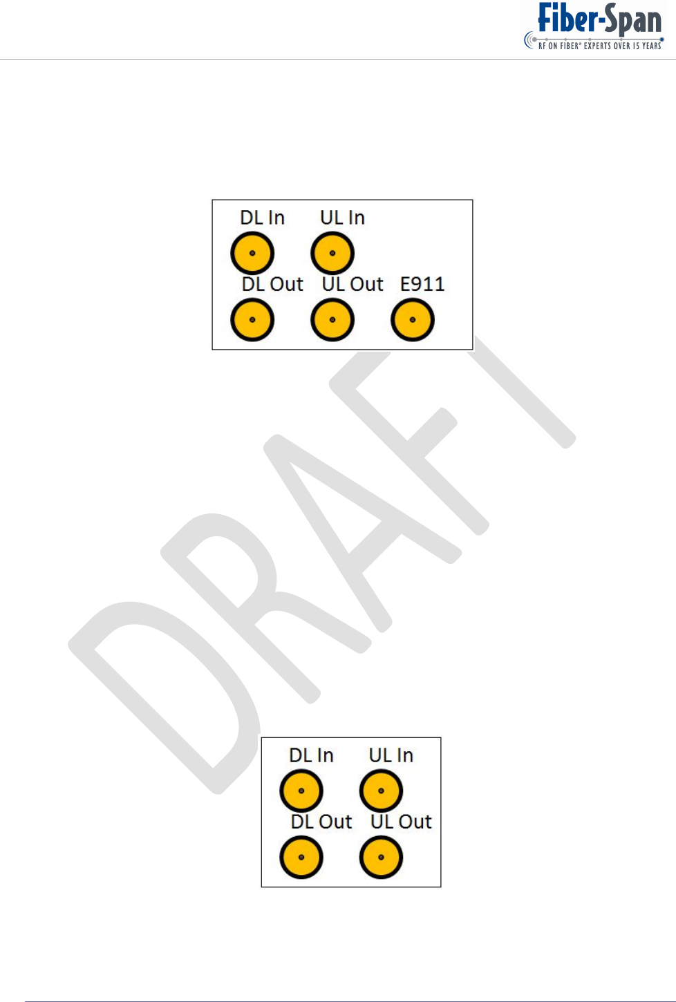
Integrated with the AWS plug-in is E911 input port that provides capability for an emergency
signal path that is combined, condition, and amplified using the same downlink output power
amplifier module. Because it is transparent not external peripherals required.
Remote Fiber Node (RFN) User Manual
©Copyright 2011, Fiber-Span Page 11 of 38
Instrument operates in the UL 1710-1755, DL 2110-2155 MHz region.
Figure 5 displays Plug-in Cell, PCS, and AWS RF connections in rear which are the same for all
three bands.
Figure 5
6.4. 700
The 700 Plug-in is a bi-directional service module comprising of uplink and downlink circuitry.
Internally it houses all the devices that conditions, filters and amplifies the specified frequency
band while rejecting the adjacent family bands operating within the chassis.
Although it accommodates both paths, circuitry is kept shielded providing 120 dB of isolation
between them which prevents any RF crossover
Circuitry is similar in the UL and DL paths, with uplink RF Gain at 40 dB while the downlink
has more gain, with the addition of a high power amplifier module that provides 40 dB to drive
the DAS for a total of 70 dB from end to end. In both directions, inserted between the pre-
amplifier and mid-amplifier is an attenuator with a 31 dB adjustment range.
Instrument operates in the UL1: 698-716, UL2: 776-787, DL 728-757 MHz regions.
Figure 6 displays Plug-in 700 RF connections in rear.
Figure 6

Remote Fiber Node (RFN) User Manual
©Copyright 2011, Fiber-Span Page 12 of 38
6.5. Cellular
The CELLULAR Plug-in is a bi-directional service module comprising of uplink and downlink
circuitry. Internally it houses all the devices that conditions, filters and amplifies the specified
frequency band while rejecting the adjacent family bands operating within the chassis.
Although it accommodates both paths, circuitry is kept shielded providing 120 dB of isolation
between them which prevents any RF crossover.
Circuitry is similar in the UL and DL paths, with uplink RF Gain at 40 dB while the downlink
has more gain, with the addition of a high power amplifier module that provides 40 dB to drive
the DAS for a total of 70 dB from end to end. In both directions, inserted between the pre-
amplifier and mid-amplifier is an attenuator with a 31 dB adjustment range.
Instrument operates in the UL 824-849, DL 869-894 MHz
Figure 5 displays RF connections in rear.
6.6. Extended PCS
The Extended PCS Plug-in is a bi-directional service module comprising of uplink and
downlink circuitry. Internally it houses all the devices that conditions, filters and amplifies the
specified frequency band while rejecting the adjacent family bands operating within the chassis.
Although it accommodates both paths, circuitry is kept shielded providing 120 dB of isolation
between them which prevents any RF crossover.
Circuitry is similar in the UL and DL paths, with uplink RF Gain at 40 dB while the downlink
has more gain, with the addition of a high power amplifier module that provides 40 dB to drive
the DAS for a total of 70 dB from end to end. In both directions, inserted between the pre-
amplifier and mid-amplifier is an attenuator with a 31 dB adjustment range.
Integrated with the Extended PCS plug-in is E911 input port that provides capability for an
emergency signal path that is combined, condition, and amplified using the same downlink
output power amplifier module. Because it is transparent not external peripherals required.
Instrument operates in the UL 1850-1915, DL 1930-1995 MHz region.
Figure 5 displays RF connections in rear.
Note: the rear plug-in RF connections shown in this section, upon looking into the RFN
chassis (facing you), the connections are mirrored.
Remote Fiber Node (RFN) User Manual
©Copyright 2011, Fiber-Span Page 13 of 38
7. Block Diagram
7.1. RFN Block diagram
800/900
MHz
800/900
MHz
LNA
LNA
PA
PA
LNA
LNA
PA
PA
LNA
LNA
PA
PA
O
E
R
X
O
E
T
X
O
E
R
X
O
E
T
X
O
E
T
X
O
E
R
X
Cellular
AWS
900 MHz
PCS
Reject 894
Reject 896
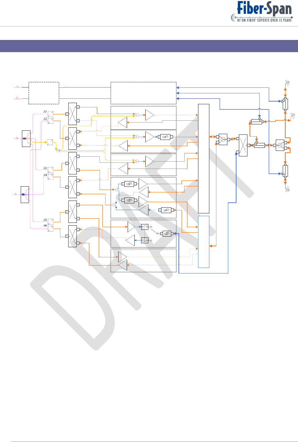
RFN Block Diagram
H
L
H
L700 MHz
AWS
700 MHz
AWS
LNA
LNA
PA
PA
LNA
LNA
PA
PA
Wi-MAX
H
L
L
H
Wi-MAX
Wi-MAX
L
H
LNA
LNA
PA
PA
L
H
Multiplexer
ACCESS POINTS
Cell
PCS
PCS
Cell
To DAS
800 MHz
700
LNA
LNA
PA
PA
RFN Plug-Ins
Service
Group 1
Service
Group 2
Service
Group 3
DWDM
De-Mux
DWDM
Mux
Ethernet Media
Converter / GE
Switch
L
L
H
H
Multiplexer
O
E
R
X
CDMA
RX
Figure 7
Figure 7 displays the internal components and their connections, including optical interfaces
which come from the left-end while the right-end are the DAS connections.
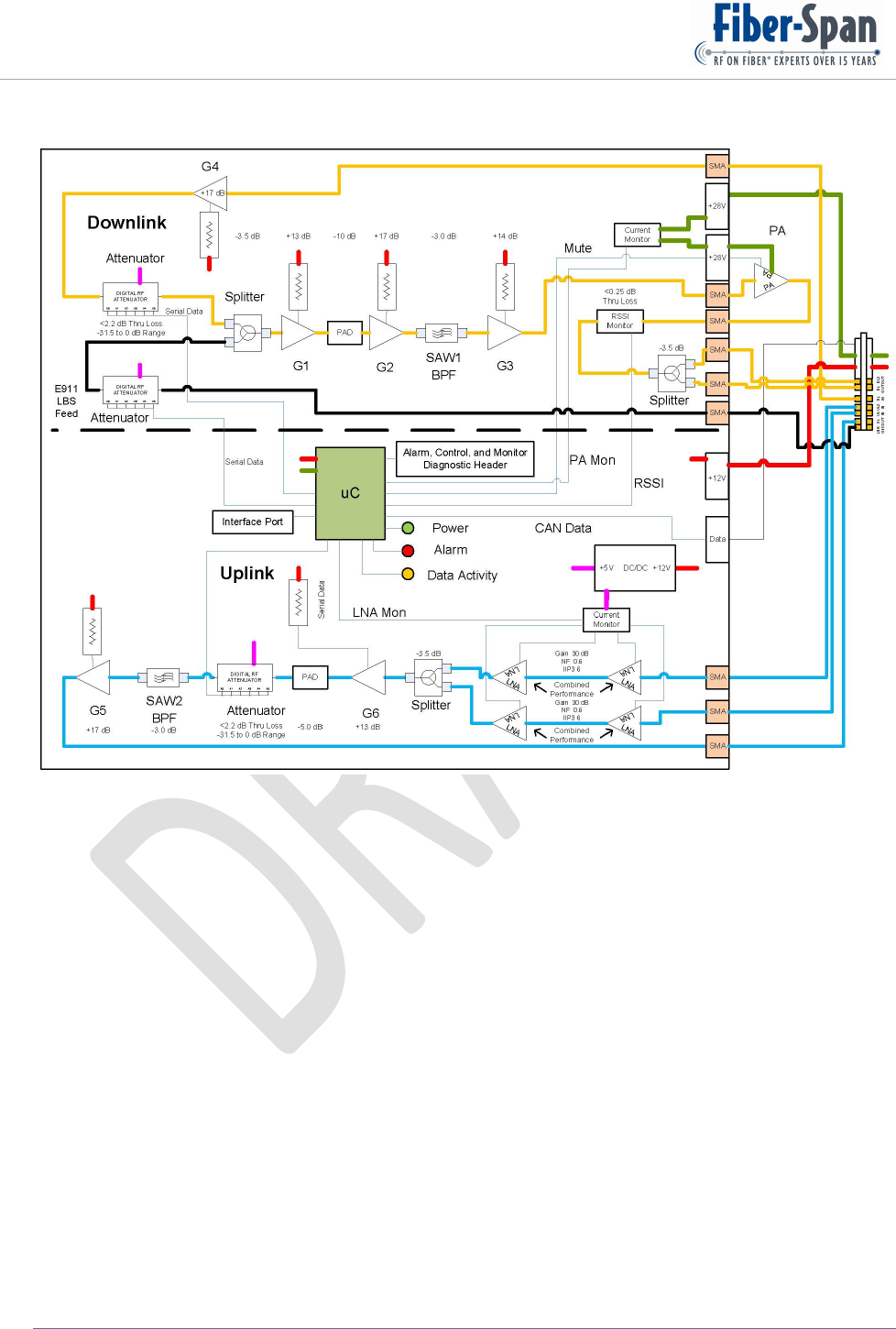
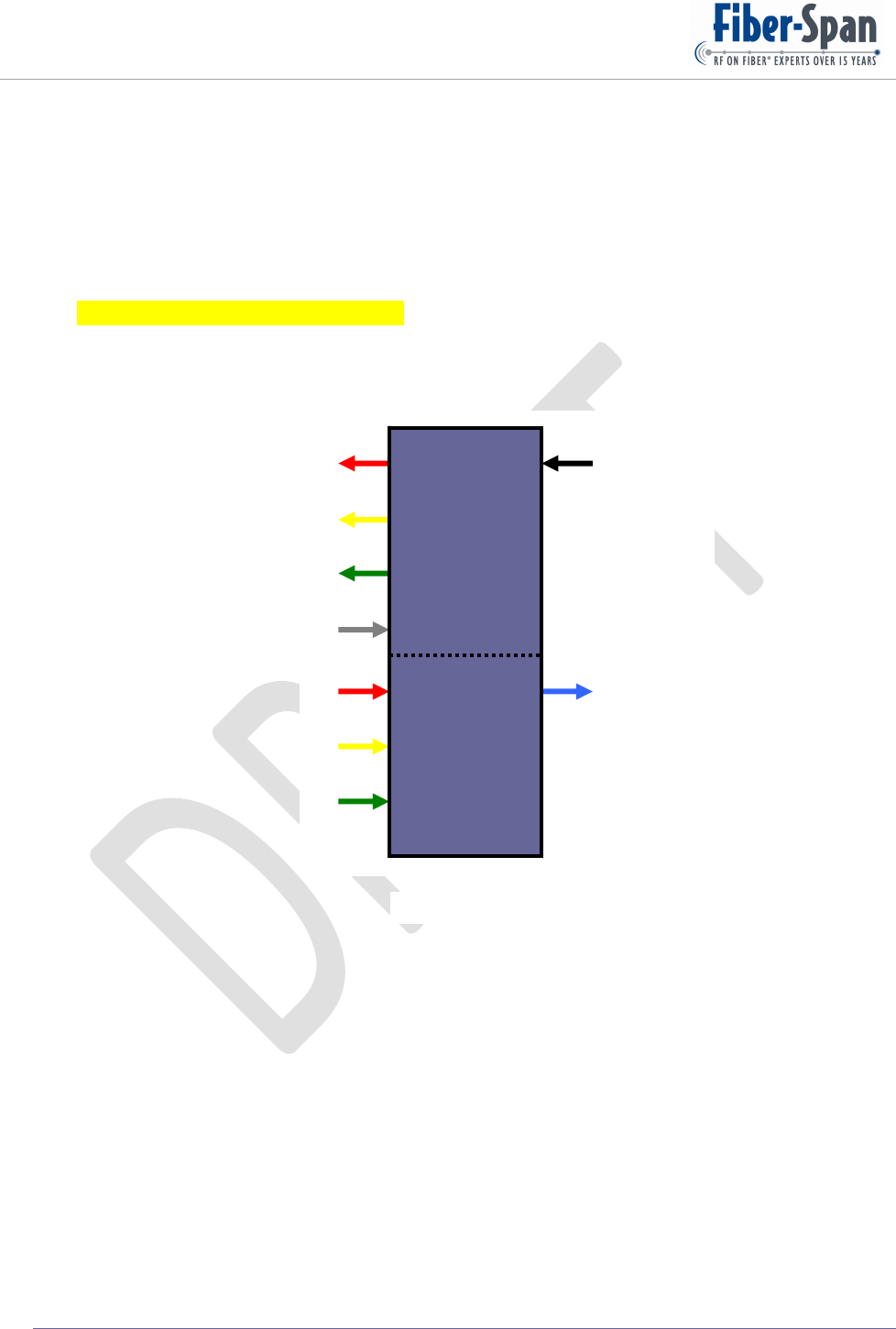
Figure 8 is a typical internal configuration of a Plug-in. As depicted, uplink and downlink are
within the confines of the plug-in but shielded from each other.
Shown on the plug-in module block diagram’s right side are the rear plug-in connectors.
Remote Fiber Node (RFN) User Manual
©Copyright 2011, Fiber-Span Page 14 of 38
7.2. Plug-in
Figure 8
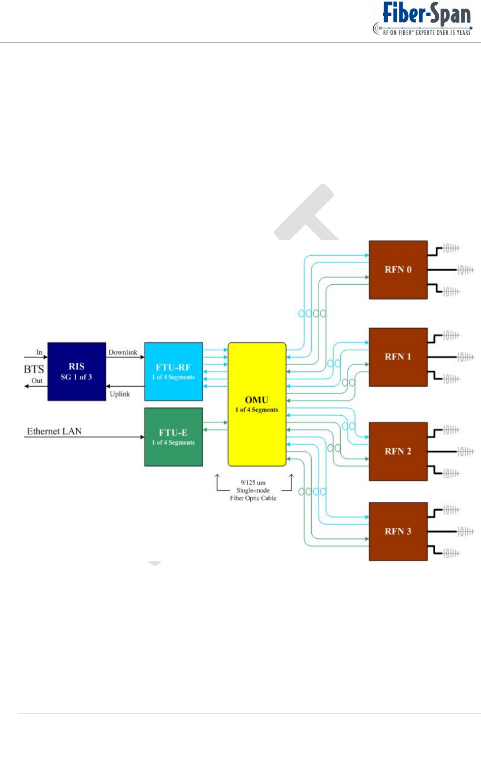
7.3. System Block Diagram
Figure 9 demonstrates a 1 x 4 system link configuration comprising of 4 RFNs and Headend
segments that makeup a link, such as OMU, FTU-RF, FTU-E and RIS. RIS is the last F-S
equipment interfacing with the end-user Base Transceiver Station (BTS).
In this section, an overview is provided of the Headend equipment incorporated as part of a
typical RFN application.
Optical Multiplex Unit (OMU) houses all the passive optical devices interfacing with incoming
and outgoing fiber bundles which are then neatly individualized, routed and channeled to
interface with the Optical Add/Drop Multiplex (OADM). Next, each designated ITU
connection interfaces with the FTU-RF and FTU-E.
Fiber Transceiver Unit – Radio Frequency (FTU-RF) houses all the active optical devices that
converts light into electrical and vice-versa launches light from received electrical. In the
receiver there is filtering, post amplification, and gain adjustability for fine tuning as required.
Remote Fiber Node (RFN) User Manual
©Copyright 2011, Fiber-Span Page 15 of 38
Fiber Transceiver Unit – Ethernet (FTU-E) houses the media converter.
??-Write a brief summary.-
Radio Interface System (RIS) houses all the RF devices that condition, filter, rssi and control
gain that is required between the BTS and FTU-RF, in part because an ideal RF level into FTU
is 0 dBm and levels from BTS are considerably higher up to 30 dBm. As planned, based on the
service group, configuration for simplex, duplex and full duplex or combination of them are
arranged in the RIS.
Fibers interconnecting the FTU-RF, OMU and RFN are 9/125 um single mode.
Fiber medium operational range is from 0 to 8 dBo optical loss.
Figure 9
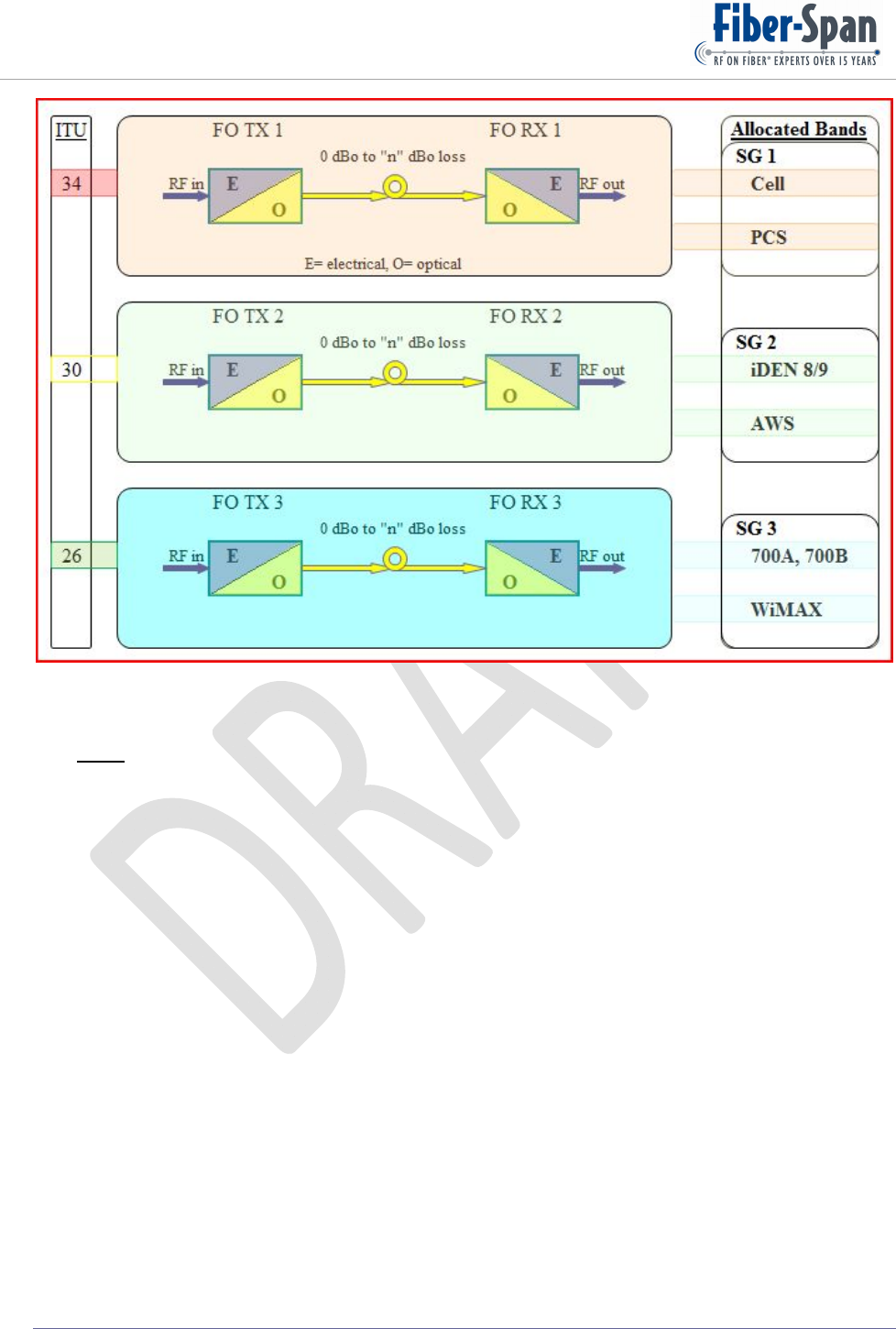
7.4. Optics
Behaving identical all 3 internal fiber optic transmitters (FOTX) that converts the electrical
input into output modulated light using a cooled distributed feedback (DFB) laser.
Figure 11 displays 3 optical links that represent the Service Groups for the downlink and
another alike setup makes up the uplink.
Figure 10
Remote Fiber Node (RFN) User Manual
©Copyright 2011, Fiber-Span Page 16 of 38
Figure 11
Note: Service Group (SG) 3 has provisions for WiMAX, pending its release.
Remote Fiber Node (RFN) User Manual
©Copyright 2011, Fiber-Span Page 17 of 38
DWDM Configuration
Tucked in the RFN lower left tier is the Add Drop Multiplex arrangement, housing all the
optics and external interface connections.
Designated optical channels are ITUs 26,30,34,38 for the downlink (DL) path and ITUs 26, 30,
34 for the uplink (UL) path which are dedicated for the Service Groups (SG1, SG2, SG3)
excluding the Ethernet paths. Duplex configuration allows use of the same ITU channels, see
Error! Reference source not found..
DL 34 Common DL Port
DL 30
DL 26
DL 38
UL 34 Common UL Port
UL 30
UL 26
Uplink
Mux
Segment
Downlink
DeMux
Segment
Figure 12

Remote Fiber Node (RFN) User Manual
©Copyright 2011, Fiber-Span Page 18 of 38
Beneath the optical housing is a shallow splice tray compartment for the end-user to loop, make
interconnections, and secure the fibers.

Remote Fiber Node (RFN) User Manual
©Copyright 2011, Fiber-Span Page 19 of 38
8. General
8.1. RF
Notwithstanding the specific operating frequency band of each plug-in, circuitry are alike with a
40 dB gain on the uplink path and 70 dB gain on the downlink path. Uplink noise figure is
optimized to be lower than 2. Downlink can drive DAS in excess of 25 dBm per band. And In
both paths, for tuning, the same attenuator device is implemented that provides 31 dB of range.
Multiplexer is the external gateway that combines all the plug-in up/down paths user interface
ports which introduces 12 dB loss for Ant1 and Ant 3 while Ant 2 has an additional 6 dB more
loss.
8.2. Optical
All optics are housed in the lower left tier compartment called “Optical Stack”, namely because
carefully inside, sections are one on top of the other. Beginning with the FOTXs, middle
FORXs and last the OADMs.
FOTX further discussion
Each unique 1.5 um wavelength is routed into their corresponding OADM channel exiting the
common conduit and launched through the interface optical port uplink path.
At factory, FOTXs are normalized called TX Set-point that regulate batch with a consistent
resultant output. Laser incorporates average optical power feedback keeping output power
steady over temperature and lifetime. For best performance laser bias is also tuned.
A typical UL FOTX optical output power is 6 dBm, minus 2 dB loss through the OADM for a
net launched of 4 dBm. Result using Optical Meter will be the composite power. But with an
optical spectrum analyzer (OSA) one or all side-to-side wavelengths spectrum are displayed on
screen for precise measurement.
Figure 13 demonstrates how the optical configuration for the downlink behaves as a function
of muxing the lasers through the OADM. Measurement at the optical port with an optical
meter yields 8.8 dBm, on the other hand measuring with an OSA outcome is 4.0 dBm for each
laser.
For the uplink path each laser launch power is typically 6 dBm but no higher than 8 dBm and
would put composite launched power at 10.8 dBm.

Remote Fiber Node (RFN) User Manual
©Copyright 2011, Fiber-Span Page 20 of 38
Figure 13
Note: Allow for 0.25 dBo loss for every interconnection.
FORX discussion
On the opposite side, complimenting is the fiber optic receiver (FORX) which converts the
optical input to an electrical output for the downlink (DL) path. By also adding an OADM in
the receiver side only matching light goes through while rejecting all others.
Most photo detector optical input limits are about 8 dBm, but the system receivers will never
see such high levels, with practical values at 5 dBm or much lower due to the external fiber
medium optical loss which is around 4 dBo.
Further explanation, with a 7 dBm source optical power at the Headend which is split 4-Ways
(-7dBo) then the OADM thru loss (-2 dBo) and a typical (-4 dBo) loss thru fiber medium,
putting the upper optical input limit of the fiber receiver at -6 dBm. So the upper limits are un-
reachable into FORX.
Alarm threshold for excessive optical loss is set to -14 dBm which is a 4 dBo margin from the
expected fiber medium maximum loss of 8 dBo.

Remote Fiber Node (RFN) User Manual
©Copyright 2011, Fiber-Span Page 21 of 38
8.3. Alarm Monitor and Control Software
8.3.1. PC Requirements
8.3.2. Launch Program
8.3.3. Firmware Revision
8.3.4. General Settings
8.3.5. Username / Password
8.3.6. Default and Status Settings
8.3.7. Block Diagram
8.3.8. Controls
8.3.9. Alarm Settings
8.3.10. Software Windows
( In ascending order insert windows of all the settings in use)
Downlink
Uplink
8.3.11. Alarms and Controls
FOTX temp, power
PA: FPM, VSWR
8.4. Connector Type
RF connections are made using DIN-female connectors.
Optical connectors are SC/APC type for downlink / uplink signal paths, and LC connectors
for Ethernet paths.
8.5. Mechanical
All Plug-ins are secured each with 10 tamper resistant pin-in-Hex socket cap screws size 8-32 x
¾ inches in length.
Bottom access panel-door is secured with twenty-one and side panel-doors each require 8
tamper resistant pin-in-Hex socket cap screws size 8-32, ½ inches in length, totaling 37.
8.6. Switches & Indicators
TBD.

Remote Fiber Node (RFN) User Manual
©Copyright 2011, Fiber-Span Page 22 of 38
9. Installation
9.1. Mounting
The wall or ceiling bolts securing unit must be sufficiently able to carry the weight of the RFN
which must be aligned properly balancing weight throughout the supports. While mounting the
RFN a platform underneath must sustained all its weight until all the mounting bolts are tighten
and secured. See outline section in this manual for bracket hole dimensions and recommended
bolt size.
Fully populated unit nearly weighs 200 lbs; therefore proper lifting equipment is required to
bear its weight during installation. Do not attempt to install equipment on your own.
For proper air flow, keep a minimum clearance of 8 inches in front, underneath and top of the
black heat-sink section of the RFN.
Allow at least 14 inches in front of the unit for removal and installation of the Plug-ins. Each
plug-in comes out independently of the other. Remove all the screws around the perimeter of
the plug-in, then to remove the plug-in, hold both handles and pull horizontally straight out
from its housing slot.
9.2. Optical Connections
Travelling from the outside 4 External 9/125 um single mode fiber strands (2- SC/APC, 2- LC
connectors) can either be inserted through the side (left or right) access panels.
See Figure 14 Side Access Panel.

Remote Fiber Node (RFN) User Manual
©Copyright 2011, Fiber-Span Page 23 of 38
Figure 14 Side Access Panel
After inserting the 4 fibers through aperture, route two, (DL and UL) fibers inside all the way
to the optical stack. See Figure 15 Optical Stack.
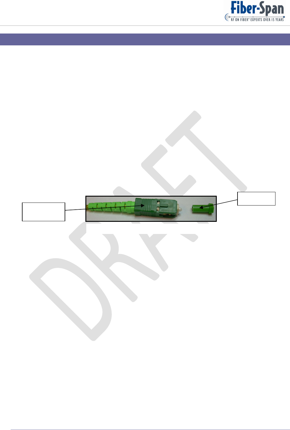
View is from underneath the RFN bottom access
panel. The DL and UL fiber strands are distinguish
by their connector type which is SC/APC type, see
Figure 16.
The inner fiber adapter (away) is the uplink path
connection and the outer fiber adapter (near) is the
downlink path connection.
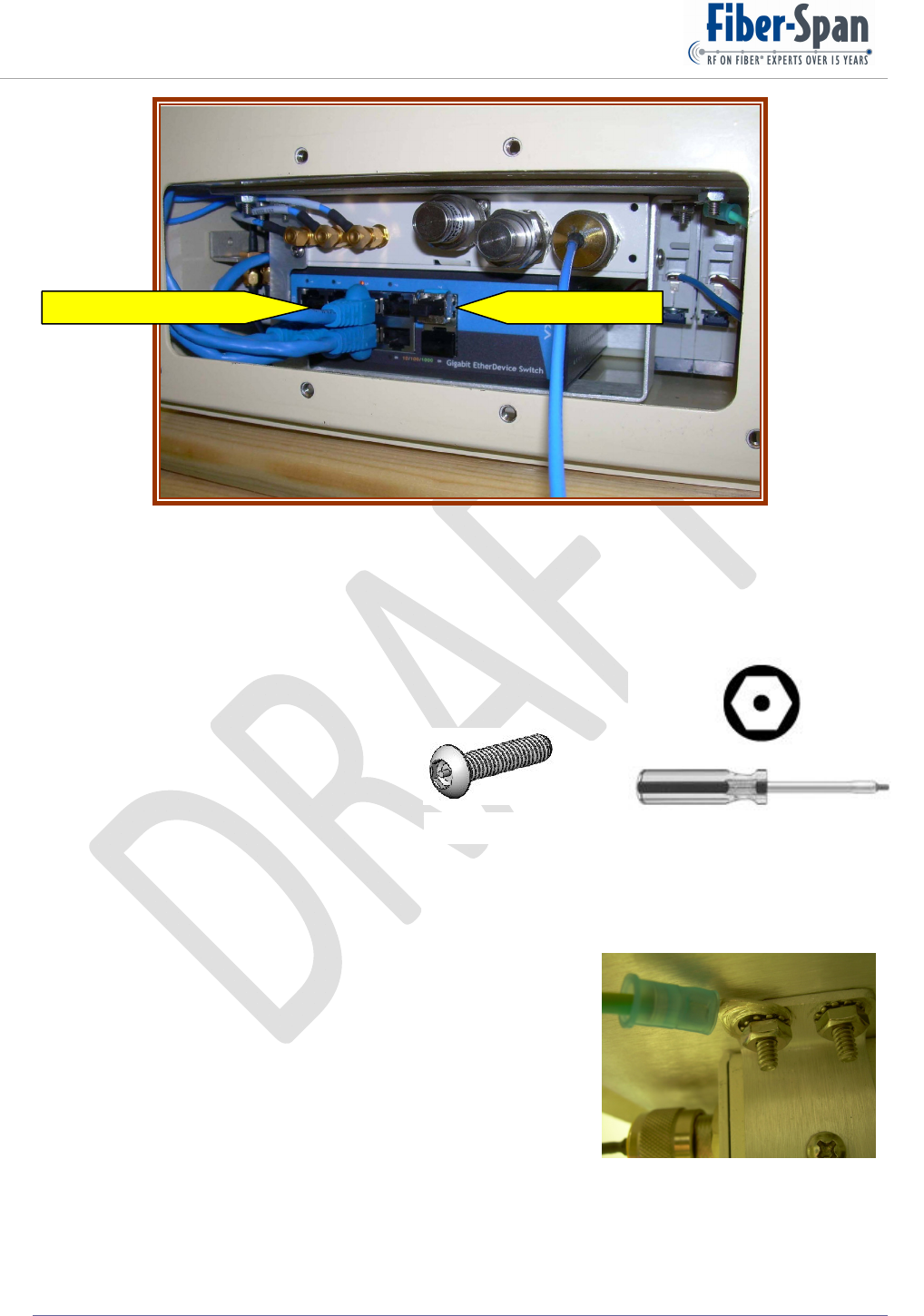
Incoming Ethernet fibers 3, 4 connect to the media
converter commonly called EtherDevice Switch
(EDS) see Figure 18. This Figure to the left also
shows the 3 Access Points connections that come
from the WiFi Plug-in.
Fiber strands for the Ethernet interface are noticeable by the dual LC connectors see Figure 17.
Here shown paired TX / RX that mate to the SFP module.
Figure 15 Optical Stack
Near
Away
Figure 17 Figure 16
Left Ant 1
Center Ant 2
Ri
g
ht Ant 3
Fibers & Power In
Remote Fiber Node (RFN) User Manual
©Copyright 2011, Fiber-Span Page 24 of 38
Figure 18
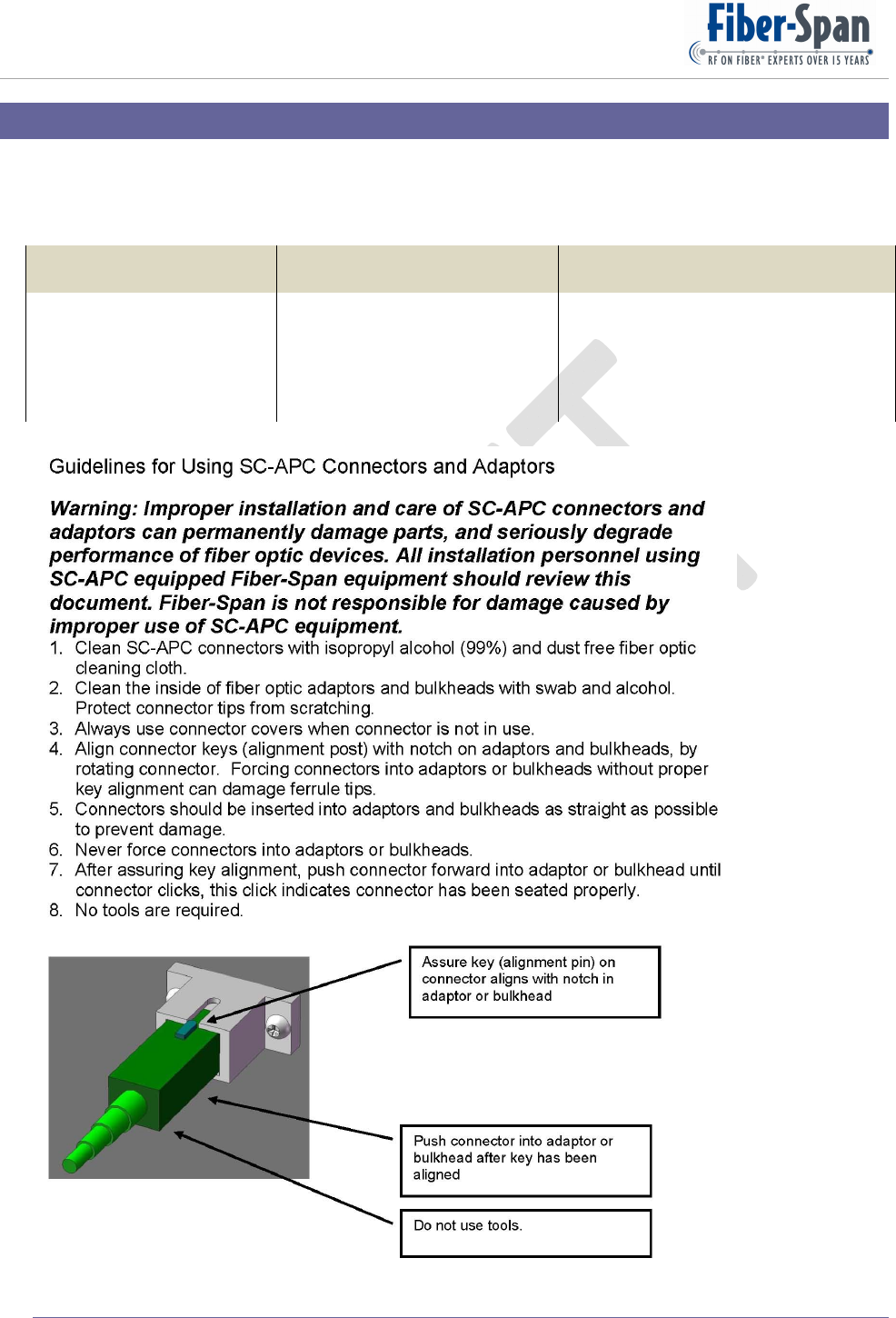
9.3. Tools
All external screws are the same head type 5-32, for Plug-in slightly longer, at ¾” and side /
bottom access panels are ½” pin-in-Hex screw, see Figure 19.
Only a single 5-32 Hex hand driver required, see Figure 20 for
Plug-in and access panel maintenance.
9.4. Grounding
Immediately inside the RFN side access panels are ground lugs to attach incoming ground
wires. See Figure 21 which shows the ground wire with lug inserted into bolt and secured with
an external tooth lock washer nut. ?? lock-nut material.
Figure 21
Figure 20
Figure 19
Ethernet Connection3 Access Point Connec
t
ions

Remote Fiber Node (RFN) User Manual
©Copyright 2011, Fiber-Span Page 25 of 38
10. General Precautions
Do not change the parameters unless instructed to do so by an authorized supervisor and
you are a qualified technician to operate instrument.
Do not attempt to move product without the proper tools and man power, because product
is extremely heavy.
Terminate all the RF ports with a 50 Ohm load prior to powering up.

Remote Fiber Node (RFN) User Manual
©Copyright 2011, Fiber-Span Page 26 of 38
11. Startup Checklist
Confirm all necessary parts accompanied product before beginning installation or operation.
11.1. Equipment List
Remote Fiber Node (RFN) fully populated*
FS42R-AP-3 FS42R-700-5
FS42R-iDEN-2 FS42R-CELL-2
FS42R-AWS-5 FS42R-PCS-5
*Does not include WiMAX Plug-in.
11.2. On Site Requirements
On site will require a 3 wire (Hot, Neutral, and Ground) 120 VAC input to the RFN including a
separate earth ground bus bar that connects to the RFN chassis.
Two 9/125 um single-mode fiber strands with SC/APC connectors, one for the downlink path
and the other for the uplink path. Two 9/125 um single-mode fiber strands with LC connectors
for the Ethernet connections.
Three high quality RF cables with DIN-Male connectors that attached from the individual DAS
antennas to the Left, Center, and Right RFN interface ports.
Remote Fiber Node (RFN) User Manual
©Copyright 2011, Fiber-Span Page 27 of 38
12. Maintenance
12.1. Periodic Inspection Checklist
Perform an On-Site assessment of the wireless coverage for use as a baseline, so that upon re-
inspecting quarterly or semiannually a comparison is made to ensure peak performance
throughout equipment lifespan.
Test and keep a record of the insertion loss of all the fiber strands that interconnect with the
equipment from end-to-end.
12.2. Preventative Measure for Optimal Operation
12.2.1. Optical Maintenance
Once optical connectors are secured the ports no maintenance is required. However when
necessary to unplug it, immediately cap the tip with cover, see Figure 22. This prevents
scratching exposed glass tip which deteriorates performance and possibly becoming unusable.
12.2.2. RF
Once RF connectors are secured no maintenance is required. However perform periodic on-
site wireless coverage assessment to compare it to the baseline this will ensure optimum
performance.
Figure 22
Cover
SC/APC
Connector
Remote Fiber Node (RFN) User Manual
©Copyright 2011, Fiber-Span Page 28 of 38
13. Factory Settings
Tuning and testing performed at factory are:
FibertransmitterFOTXFiberreceiverFORXRF
Opticalpower
TXSet‐point
LaserBias
TemperatureAlarm
Opticalminimuminput
threshold
Gainat4dBoloss
AttenuationRange
Twotoneintermodulation
interceptpoint
OutputNoise
Remote Fiber Node (RFN) User Manual
©Copyright 2011, Fiber-Span Page 29 of 38
Figure 23
Figure 24
14. Specifications
14.1. Electrical Specifications
Externally 3 wires (Hot, Neutral, Ground) conduit route through either
side (left / right) access panel orifice (Hot, Neutral) go to two in-line
breakers that connect to VAC In (range 85-265) power supply,
Outputting 28 Volt DC with 600 Watts capability providing power to all
the power amplifiers and in part regulated to 48 and 12 Volts for
discrete devices.
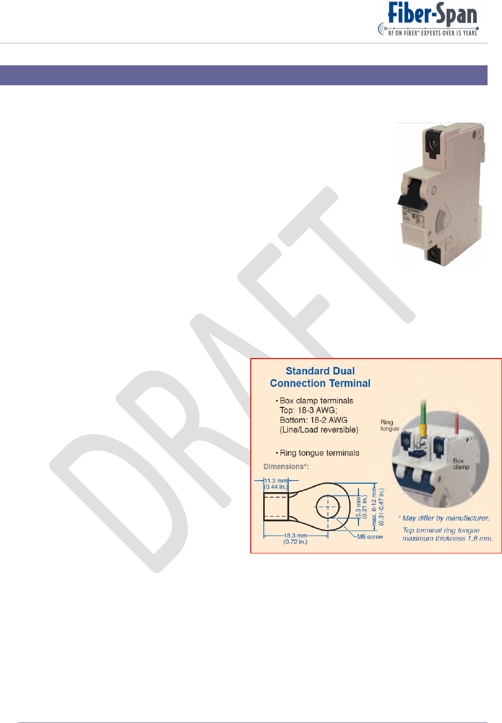
The Hot and Neutral wires connect internally to 2 in-line 1 pole 10 amp
circuit breaker (FS-Pn 760-0025 see Figure 23), mfr’s pn 1BU10 by
Altech Corp., that provides RFN protection.
Incoming external ground (GND) wire connects inside to a chassis
ground lug.
In the event primary power supply shuts off, as backup, design incorporates a second parallel
equivalent power supply so that the equipment will continue to operate without interruption.
Both breakers are DIN Rail mounted and
have the UL508 safety standard.
For recommended terminal connection to
the circuit breaker see Figure 24.
14.1.1. FS47R
Fully populated including WiMAX,
AC Current is 4.3 Amps / 120 VAC.
14.1.2. Plug-in
All VCC plug-ins are 28 Volts, except
FS42R-AP-3 which is 48 Volts. Figure 25
shows current for each plug-in.

Remote Fiber Node (RFN) User Manual
©Copyright 2011, Fiber-Span Page 30 of 38
ItemCurrent(A)
FS42R‐AP‐30.81
FS42R‐IDEN‐23.63
FS42R‐AWS‐54.00
FS42R‐700‐53.18
FS42R‐CELL‐22.58
FS42R‐PCS‐52.58
Figure 25
14.2. Mechanical Specifications
14.2.1. Chassis
Fully populated (7 Slots) weighs 198 lbs.
14.2.2. Plug-in
Plug-in typical weight is 12 lbs.
14.3. Other Specifications
Approvals testing in process for IP66 environmental rating.
(i.e., MTBF, FCC, Underwriters Laboratory, IP66, Certificates, Warranty)
Remote Fiber Node (RFN) User Manual
©Copyright 2011, Fiber-Span Page 31 of 38
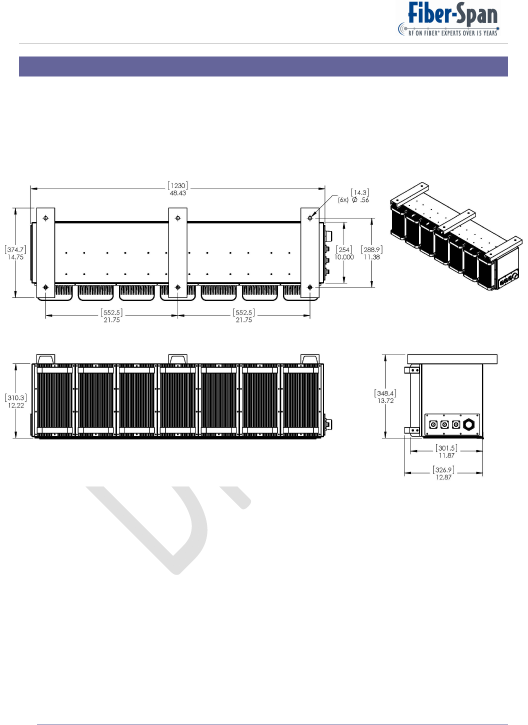
15. Outline Drawing
An outline drawing of the RFN is shown below. Dimensions are in inches [enclosed brackets in
mm].
Remote Fiber Node (RFN) User Manual
©Copyright 2011, Fiber-Span Page 32 of 38
Figure 26
16. Illustrations
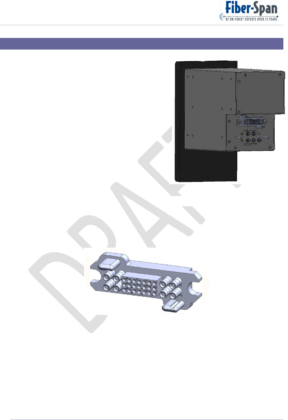
16.1. Internal
All plug-in modules are identical in size. Rear DC
connections are the same pin-out while RF
connections are custom to each plug-in. Figure 26 is
the isometric rear view of a plug-in. The downward
extended black facade is the heat sink which
maximizes surface area, and thus heat transfer.
16.2. External
??-del- Include identification of all the ports.
16.3. Plug-in DC
Figure 27 displays the DC connector in rear of all the plug-
ins. It also provides the data connection between
the plug-ins and the Alarm Monitor and Control network. As shown in the illustration, diagonal
corners have a locking flat pin that blindly aligns with the mating socket.
Figure 27

Remote Fiber Node (RFN) User Manual
©Copyright 2011, Fiber-Span Page 33 of 38
17. Troubleshooting
The RFN is designed and built to provide trouble-free performance without the need for service. If
it does not appear to be functioning properly, please follow these troubleshooting steps.
17.1. RF
17.2. Optics
17.3. Ethernet

Remote Fiber Node (RFN) User Manual
©Copyright 2011, Fiber-Span Page 34 of 38
18. Warranty
18.1. General Warranty
The RFN carries a standard warranty period of one (1) year unless otherwise indicated on the
shipping packages as noted in the purchase order agreement.
18.2. Limitations of Warranty
The warranty is limited to the repair or replacement of the defective product. Fiber-Span will
decide which remedy to provide for defective components as its own discretion. Fiber-Span
shall have a reasonable time after determining that a defective product exists to repair or replace
the problem unit. The warranty applies to any repaired or replaced products for the balance of
the applicable period of the original warranty or ninety (90) days from date of shipment of a
repaired or replaced component, whichever is longer.
The Fiber-Span standard warranty does not cover products which have been received
improperly packaged, altered, or physically damaged. For example, broken warranty seal, labels
exhibiting tampering, physically abused enclosure, broken pins on connectors, any
modifications made without Fiber-Span authorization, will void all warranty.
18.3. Limitations of Damages
The liability for any defective product shall in no event exceed the purchase price for the
defective product. Fiber-Span has no liability for general, consequential, incidental or special
damages.
18.4. Return Material Authorization (RMA)
No product may be returned directly to Fiber-Span without first getting an approval from
Fiber-Span. If it is determined that the product may be defective, you will be given an RMA
number and instructions in how to return the product.
An unauthorized return, i.e., one for which an RMA number has not been issued, will be
returned to you at your expense. Authorized returns are to be shipped to the address on the
RMA in an approved shipping container. It is suggested that the original box and packaging
materials should be kept if a defective product needs to be shipped back to Fiber-Span.
To request an RMA, please call 908.253.9080.

Remote Fiber Node (RFN) User Manual
©Copyright 2011, Fiber-Span Page 35 of 38
19. FCC Required Statement
Manufacturers Notes
“Changesormodificationsnotexpresslyapprovedbythemanufacturercould“Void”the
user’sauthoritytooperatetheequipment”.
ThisequipmenthasbeentestedandfoundtocomplywiththelimitsforaClassAdigital
device,pursuanttoPart15oftheFCCRules.Theselimitsaredesignedtoprovide
reasonableprotectionagainstharmfulinterferencewhentheequipmentisoperatedina
commercialenvironment.Thisequipmentgenerates,uses,andcanradiateradio
frequencyenergyand,ifnotinstalledandusedinaccordancewiththeinstructions
manual,maycauseharmfulinterferencetoradiocommunications.Operationofthis
equipmentinaresidentialareaislikelytocauseharmfulinterferenceinwhichcasethe
userwillberequiredtocorrecttheinterferenceattheirownexpense.
Thisdevicehasbeendesignatedtooperatewiththeantennashavingamaximumgainof
[9]dBifora1meterdistanceandantennashavingagaingreaterthan[15]dBiarestrictly
prohibitedforusewiththisdevice.Therequiredantennaimpedanceis[50]Ohms.
To improve and correct equipment performance the following can be performed.
1. Re-orient or relocate the receiving antenna.
2. Increase the separation between the equipment and receiver.
3. Connect the equipment into an outlet on a different circuit from that to which the receiver is
connected.
4. Consult the dealer or an experienced radio/TV technician for help.

Remote Fiber Node (RFN) User Manual
©Copyright 2011, Fiber-Span Page 36 of 38
20. Glossary
dBeunitofmeasureforRF.
dBounitofmeasureforOpticallosswhich
translates1dBoequals2dBeinRF.
DASDistributedAntennaSystem
DWDMDenseWavelengthDivisionMultiplex
FOFiberOptic
F1,F2Frequencyone,Frequencytwoalsocalledtones
Headend
Housesthelocalfibertransmitter/receiver
andinterfaceswiththeBasetransceiver
station
MbpsMegabitspersecond
RFRadioFrequency
RFNRemoteFiberNode
RXReceiver
SASpectrumAnalyzer
SFDRSpurFreeDynamicRange
SG1SignalGenerator1alsocalledsignalsource
SG2SignalGenerator2
TOIThirdOrderInterceptalsocalledOIP3
TTTTwoToneTest
TXTransmitter

Remote Fiber Node (RFN) User Manual
©Copyright 2011, Fiber-Span Page 37 of 38
21. Reference Documents
-del- Include list of critical loose leaflets documents comprising user manual.

Remote Fiber Node (RFN) User Manual
©Copyright 2011, Fiber-Span Page 38 of 38
22. Company Information