Fiber Span FS51C-85 800 MHz CHANNELIZED BDA User Manual FS51C 85 USR Rev B
Fiber-Span LLC 800 MHz CHANNELIZED BDA FS51C 85 USR Rev B
Users Manual

FS51C Channelized BDA Product Series
User Manual
FS51C-85-USR
Part of Fiber-Span’s FS51C Series family of products

FS51C-85-USR
User Manual Ver. B
Document ID: FS51C Page 2 of 23
This page was left intentionally blank

FS51C-85-USR
User Manual Ver. B
Document ID: FS51C Page 3 of 23
Version B
Information in this document is subject to change without notice.
All rights reserved.
Please send comments to:
E-mail: carlitom@fiber-span.com
Phone: 908-754-0646
Fax: 908-754-0647
Revision History
Version Author Description Date
A Carlito Muniz Initial Release March 5, 2009
B CM Additional notes added April 14, 2009

FS51C-85-USR
User Manual Ver. B
Document ID: FS51C Page 4 of 23
Table of Contents
1Company Info .......................................................................................................... 5
2Product Intro ........................................................................................................... 5
3Description .............................................................................................................. 6
3.1Theory of Operation ........................................................................................................ 6
3.2Product Applications ....................................................................................................... 8
3.3System Channel(s) Expandability ................................................................................... 8
4Product Frequency Options .................................................................................. 9
4.1VHF ................................................................................................................................ 9
4.2UHF .............................................................................................................................. 10
4.3800 ................................................................................................................................ 10
5Detailed Description ............................................................................................. 10
5.1Uplink Hardware ........................................................................................................... 10
5.2Downlink Hardware ...................................................................................................... 10
6TCC RF Signal Spectrum ..................................................................................... 10
6.1Before Signal Conditioning ........................................................................................... 10
6.2After Signal Conditioning .............................................................................................. 11
7Cautionary Notes .................................................................................................. 12
8Contents ................................................................................................................ 12
9Installation Procedures ........................................................................................ 12
9.1Connectorization ........................................................................................................... 13
9.2Grounding ..................................................................................................................... 13
9.3Hardware required ........................................................................................................ 13
10RF Level calculations ........................................................................................ 13
11Specifications .................................................................................................... 14
11.1.1RF Specifications .................................................................................................. 14
11.1.2Visual Indicators & Alarms .................................................................................... 15
11.1.3Mechanical Specifications ..................................................................................... 15
11.1.4Environmental Specifications ................................................................................ 16
12Outline Drawing ................................................................................................. 17
13Troubleshooting ................................................................................................ 18
13.1RF Level Measurements .............................................................................................. 18
13.2One-Channel (Path) Ch-BDA Block Diagram ............................................................... 19
14FCC Required Statement .................................................................................. 21
14.1Manufacturer Notes ...................................................................................................... 21
15Glossary ............................................................................................................. 22
16Warranty Information ........................................................................................ 23
16.1Warranty Limitations ..................................................................................................... 23
16.2Limitations of Damages ................................................................................................ 23
16.3Return Material Authorization (RMA) ............................................................................ 23

FS51C-85-USR
User Manual Ver. B
Document ID: FS51C Page 5 of 23
1 Company Info
Fiber-Span is a premier provider of advanced RF ON FIBER ® technologies and solutions for
fiber optic based transmission of high fidelity radio-frequency wireless voice, data and
multiservice networking applications. Fiber-Span's proprietary RF/Fiber Optic transceivers,
transmitters and receivers are rugged, compact OEM modules and subsystems designed for
easy integration into commercial cellular, GSM, PCS/PCN, M/LMDS, WLL, IF, satellite terminal
or distinctive antenna system configurations. Fiber-Span is addressing public safety needs by
providing fiber optic wireless solutions for police, fire, emergency, first responder and Homeland
Security radio systems applications. Fiber-Span's solutions for Defense and Military
organizations are also leading the way by providing reliable and secure communications links
for ground, airborne, shipboard, radar, telemetry, GPS and intelligence solutions in the
HF/UHF/VHF and microwave radio frequencies. Fiber-Span's evolving class of product
addresses the growing demand and movement toward the convergence of wire line and
wireless networks, and the requirement for high performance, high bandwidth RF ON FIBER ®
solutions and networks. Fiber-Span's customers are global wireless communication systems
original equipment manufacturers (OEM), radio frequency (RF) system integrators, and military
system architects. More information about Fiber-Span products is available from the contact info
listed below.
To support the Public Safety, Government and Military Market, Fiber-Span has diversified its
Product Line to include Class A Channelized BDAs because emergency communication
depends on it.
Fiber-Span
111 Corporate Boulevard,
South Plainfield, NJ 07080
Email: techinfo@fiber-span.com
Web: http://www.fiber-span.com/
2 Product Intro
This manual covers the Class A Channelized BDA Product Line. All primary frequency bands
for public safety are accommodated with the product series such as VHF, UHF and the 800
MHz Bands. The Class A Channelized Bi-Directional Amplifier (BDA) is a 2 Way Uplink &
Downlink Full Duplex system that uses a low isolation duplexer to minimize space required. To
use the Trunked Repeater Technology very low RF Delay is required and ranges from 32u to
120u second delay. Using the correct filtering technology has to offer is design and
implemented into the circuitry to minimize time and provide the most dense adjacent channels
possible for the high demand of communication.
The main function of a Class A Channelized BDA is to provide a constant channel frequency RF
output level while preventing other undesired channel frequencies from passing through the
Trunked Channel Card.

FS51C-85-USR
User Manual Ver. B
Document ID: FS51C Page 6 of 23
3 Description
The most popular configuration (but not limited to) is an 8 Channel Bi-Directional Amplifier,
consisting of 8 Uplink and 8 Downlink Channelized amplifier configurations. A combination of a
Trunked Channel System (TCS) and Broadband (BB) can be implemented to accommodate
your needs and budget. Each Trunked Channel Card (TCC) is “Field Programmable” to allow
for on the fly frequency setting, sensitivity and threshold change. The software “FS51C-xx-
SFT1”, (xx= band) selection is used to control frequency, sensitivity, RF level output and
threshold adjustment. Each channel can be independently programmed for “Key” time out and
shutdown. The TCC front panel has a “Lock” and “Key” illuminator for visible approval.
The 8 Channel Up/Down BDA configuration fits in 16U rack spacing. The rack spacing
mentioned does not include duplexer or custom configurations. All major RF Ports,
Communication Ports and Indicators are visible and accessible via the front panel. Power and
Alarms are connected via the rear panel.
Each major section is defined as a “Cluster”. A “Cluster” is defined as a 1U RF Splitter, 3U Card
Cage /w 12V Power Supply, xTCC Cards, x= 1 or up to 8 TCC cards and a 1U RF Combiner.
The 3U RF Power Amp is not part of the Cluster.
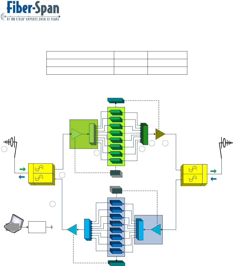
See Figure 1 typical system architecture.
3.1 Theory of Operation
8 Channel Bi- Directional Amplifiers (CH-BDA)
The eight channel bi-directional amplifier utilizes 16 trunked channel card of synchronized down-
up conversions. The multi-channel booster is divided into two independent 8 channel systems (8
high bands and 8 low Bands) for full duplex operations. Downlink signals are received from a
“Donor Antenna” (DA). 8 selected frequencies are processed (filtered and amplified), and
rebroadcast on radiating cable. The frequencies can also be joined with a Duplexer located on
the end to be rebroadcast with a “Coverage Antenna”(CA). Conversely, uplink signals induced
onto radiating cable are similarly processed and rebroadcast on the “Donor Antenna”. The
downlink channels are the high band signals (850-869 MHz), and the 8 uplink channels are low
band (820-824 MHz).
Each system consist of a LNA/8-way splitter, 8 channel modules (down-up converters with
synthesized LO), 8-way combiner, and RF power amplifiers with an 8-way power combiner. In
addition a duplexer combines the uplink RF output and downlink RF input to a common “Off the
Air” antenna.
The RF signal flow of the two systems is identical. RF band pass filters internal to the system
modules determine high band or low band operations. (Refer to system block diagram Figure1):
DUPLEXER (DUP):
The duplexer allows for full duplex operation, simultaneous transmit and receive into a common
antenna port. The pass/reject filtering of the duplexer provides band pre-selection, minimal
insertion loss between the antenna port to the two ports, transmit and receive ports, and provides
high isolation between the transmit and receive ports. For proper operations, the uplink Booster
Amp ( BA), is connected to the DA, and the downlink BA’s transmit and receive ports to the

FS51C-85-USR
User Manual Ver. B
Document ID: FS51C Page 7 of 23
radiating cable or the CA.
DUPLEXER CONFIGURATION:
UPLINK BA: The antenna port of the duplexer is connected to the “Off the Air” antenna. The
duplexer transmit port (low band) is connected to the uplink RF power amplifier output port. The
duplexer receive port (high band) is externally cabled to the downlink BA’s LNA/8 way splitter for
processing of the
downlink signals. The uplink BA’s LNA/8 way splitter (receive port) is externally cabled to radiating
cable for processing and broadcast the uplink signals on the “Off the Air” antenna.
DOWNLINK BA: The uplink duplexer’s receive port is externally cabled from the uplink BA to the
Downlink BA’s input, LNA/8 way splitter, for processing of the outbound signals. The downlink RF
output is externally cabled to inject the downlink signals onto the radiating cable.
LNA/8-WAY SPLITTER (SPL):
The LNA/8-way consists of a low noise amplifier with band pass filter, to provide band pre-
selection and amplification of the received signal, and an 8-way splitter. In the LNA module, the
operational band is selected by helical band pass filters. For low band, uplink operation, the filter
is centered at 821.5 MHz. For high band, downlink, operation, the filter is centered at 866.5 MHz.
The 8-way splits the LNA output to the inputs of the 8 channel modules.
Splitter output port “1” goes to the input of TCC channel module “1”, “2” to the input of TCC channel
module “2” and the sequence repeats through all 8 channels.
CHANNEL MODULE (TCC):
The CHANNEL MODULE is a synchronized down-up converter to provide a high degree of
filtering and hard limiting of a channel frequency, with a micro-controller to monitor and control the
module functions.
CHANNEL MODULE: The TCC module consists of 3 components:
1. The input board provides for additional channel pre-selection and amplifier of the received RF
signal. Down conversion of the signal received to an IF of 90 MHz, two cascade crystal filters
provides a high degree of filtering.
2. The output module provides hard limiting of the IF, eliminates the requirements of an
Automatic Gain Control (AGC) loop. An analog Receive Signal Strength Indicator (RSSI) from
the IF is compared to a threshold setting to produce a logic output, RSSI KEY. This signal is
monitored by the micro-controller to produce the key line and key line time-out functions.
Keying the final stages of the output module and the final RF power amplifier prevents
unwanted spurious outputs when no sign carrier is detected. In addition, the output module
provides the up conversion and filtering to the original frequency. With hard limiting at the IF
frequency, a constant output level verssus the input level is produced.
3. A dual output synthesized Local Oscillator (LO). Synchronized conversions mean that the
frequency received equals the frequency transmitted. The synthesizer output (Fc+90Mhz)
determines the channel frequency and is programmable in 12.5Khz steps to produce the
25Khz channel spacing over the pre-selected band. A Time Clock Oscillator (TCO) of 8 MHz
provides the reference oscillator to the Phase Lock Loop (PLL).

FS51C-85-USR
User Manual Ver. B
Document ID: FS51C Page 8 of 23
MICRO CONTROLLER (MC): The controller performs 4 functions:
• Programs the TCC module synthesizer to the desired frequency and monitors lock detect for
fault detection.
• Monitors the carrier detects, RSSI KEY, and generates the key line function.
• Performs the key line time out and delay functions, the time-out timer.
• Interface to the operator. Using a laptop computer and Fiber-Span proprietary software, the
operator can program the channel frequency and time-out functions.
8-WAY COMBINER (CBR):
The 8-way combines the eight TCC outputs to one. 8-way’s pre-driver adds additional filtering of
the channel modules output, and amplifies to a sufficient level to drive the power amplifier.
RF POWER AMPLIFIER (PA):
The final RF power amplifier consists of two pre-driver amplifier stages and a final hybrid class
(A) RF power module. To “key off” the power amp, the second pre-drive amplifier is controlled
(on/off) by the microcontroller output, key line, from the associated channel module.
Programmable input attenuators allow for control and setting of the final output power per carrier.
See Figure 1 for a typical system architecture.
3.2 Product Applications
The Channelized BDA is used in the following applications:
1) Underground parking structures
2) Large buildings
3) Tunnels
4) Sports stadiums
5) Shopping malls
3.3 System Channel(s) Expandability
The system architecture is expandable and additional TCC cards can be added to
accommodate more frequency channels. When the channels exceeds 8 a second “Card Cage
Cluster (CCC)” will be required adjacent to the existing CCC. A 2 Way RF Splitter and 2 Way
RF Combiner is used to interface with the extended hardware to a common port that will be fed
into the RF Power Amp. The configuration is adapted to both uplink and downlink paths.
FS51C-85-USR
User Manual Ver. B
Document ID: FS51C Page 9 of 23
Table 1
Signal Direction Port Label Port Label
Downlink Path DL RF In DL RF Out
Uplink Path UL RF In UL RF Out
Figure 1
Figure 1 shows a typical 8 Channel, Channelized BDA Uplink/ Downlink System Architecture
4 Product Frequency Options
4.1 VHF
Available products sold for VHF frequency bands.
Down Link
Cluster 1
TCC 1
TCC 3
TCC 2
TCC 4
TCC 6
TCC 5
TCC 7
TCC 8
1x8 Splitter
12V PS
Amp 1
Alarms
1x8 Combiner
Power Amp 1
Up Link
Cluster 1
TCC 1
TCC 3
TCC 2
TCC 4
TCC 6
TCC 5
TCC 7
TCC 8
1x8 Splitter
12V PS
Amp 2
Alarms
1x8 Combiner
Power Amp 1
Com
Hi
Low
Duplexer
Donor
Antenna
RP1
RP2
RP3
RP4
RP5 RP6
Uplink
Path
Downlink
Path
Reference Points= RP#
Coverage
Antenna
Com
Hi
Low
Duplexer
Uplink
Path
Downlink
Path
Laptop
Connects to each
TCC Card via RS232
Cable to set the
desired Frequency
DB9

FS51C-85-USR
User Manual Ver. B
Document ID: FS51C Page 10 of 23
4.2 UHF
Available products sold for UHF frequency bands.
4.3 800
Available products sold for 800 frequency bands. This user manual covers the 800 MHz band.
5 Detailed Description
This section deals with the components (variations) that are assembled to make up the
Channelized BDA main subassemblies:
5.1 Uplink Hardware
1. One 1 x 8 Way RF Splitter (SPL)
2. Eight Trunked Channel Cards (TCC) inside Card Cage w/ 12 Volt Power Supply
3. One 1 x 8 Way RF Combiner (CBR)
4. One RF Power Amp (PA)
5.2 Downlink Hardware
1. One 1 x 8 Way RF Splitter (SPL)
2. Eight Trunked Channel Cards (TCC) inside Card Cage w/ 12 Volt Power Supply
3. One 1 x 8 Way RF Combiner (CBR)
4. One RF Power Amp (PA)
One Duplexer is used for both Uplink and Downlink Channelized BDA.
6 TCC RF Signal Spectrum
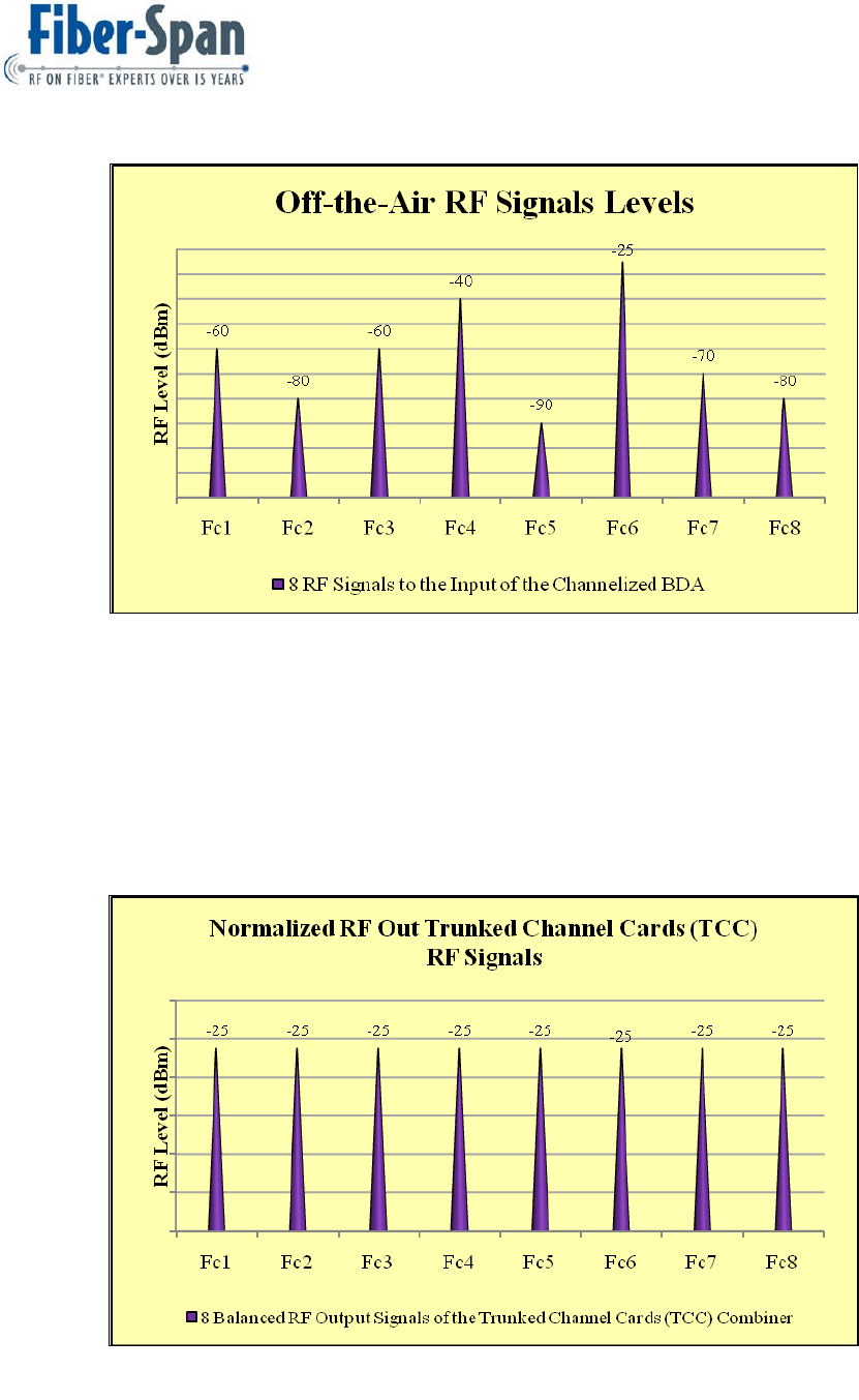
6.1 Before Signal Conditioning
Figure 2 graph displays the “Off-the-Air” RF signals picked up from the Donor Antenna. The RF
Signals will be transported until they have reached the RF Input of the RF “Common” port
Splitter. After the RF Splitter, each corresponding TCC card will accept one of the many
channel frequencies.
FS51C-85-USR
User Manual Ver. B
Document ID: FS51C Page 11 of 23
Figure 2
6.2 After Signal Conditioning
Figure 3 graph displays the Normalized RF Signals conditioned by the TCC cards. All the
channel frequencies are present at the “Common” RF Combiner port. RF Signals will then be
transported to the RF Input of the Power Amp where they will be amplified at the desired
Automatic Level Control (ALC).
Figure 3

FS51C-85-USR
User Manual Ver. B
Document ID: FS51C Page 12 of 23
7 Cautionary Notes
WARNINGS:
1) TCC Cards are Not Hot Swappable. Turn Off Card Cage prior to removing or installing
card(s).
2) Confirm RF levels do not exceed unit capability prior to connecting.
3) All RF ports must be properly terminated prior to applying power to the external
equipment.
4) Always connect the RF Outputs of a unit first then connect the RF Inputs.
5) Unused RF ports should be terminated with 50 ohms. Failure to properly terminate an
RF port may result in damage to the unit.
6) It is recommended that the entire manual be read prior to installing the unit by an
authorized technician.
7) Always turn “Off” equipment prior to installing or removing the TCC cards, RF
Splitters, RF Combiner or Active hardware from the chassis. Product is “Not” Hot
Swappable.
8) Electrostatic Discharge ESD
Use precautions when touching equipment. Make sure body has been statically discharged by
grounding yourself to an ESD grounding strap. This will prevent damage to sensitive
components inside the unit.
8 Contents
Included with the 8 Channel Up/Down Channelized BDA when shipped:
o Outline Drawing
o Test Data
o Software (Controls Sensitivity, Threshold and Levels)
o Software Operational Manual (OPM)
o User Manual (this manual)
9 Installation Procedures
Fiber-Span’s Channelized BDA is made to operate in an internal or external environment such
as a telecom room or an outside dwelling. It is recommended that the temperature inside the
room does not exceed +60°C or be below -20°C. The humidity must be 10% to 95%.
FS51C-85-USR
User Manual Ver. B
Document ID: FS51C Page 13 of 23
9.1 Connectorization
The Channelized is supplied with an N-female (see Figure 4) connector on all the main port(s).
Between the “RF Splitter”, “TCC Cluster” and “ RF Combiner” the RF connections are “SMA-
female” It is recommended that a 3 ft jumper cable is used in a (S) shape as a strain relief to
connect the main TX and RX ports to the coaxial cable going into the “Non Fiber-Span
equipment”. This will avoid the likelihood of the RF port to strip. See figure 8 for connector
types, make sure the RF cable connector is aligned with the unit port when threading. Soft jaw
connector pliers are commonly used when tightening the RF cable connector.
Figure 4
9.2 Grounding
The Channelized BDA Cabinet has a main separate ground lug. Common ground connections
are via the VAC Ground strip. Do not use plastic or nylon washers between any mounting
screws which attach the hardware to the cabinet.
9.3 Hardware required
All “Hardware Kit” to make up a Channelized BDA is included. Foreign RF Cables and third
party products are not included; however, are offered by Fiber-Span at a nominal cost.
10 RF Level calculations
Downlink and Uplink desired RF Input to Power Amp use the following calculation to determine
nominal RF levels into the input port of the RF Power Amp (PA)
Step 1:
Equation 1: RF input level to PA per Channel = PA RF ALC Level (dBm) – PA Gain
Step2:
Equation 2: When the RF Level to the input of the PA is higher than desired, a PAD can be
inserted in series to the PA RF Input port.
PA RF Input minus PAD value equals New RF Input to PA(dBm)
-20 - 10 = -30
ALC minus PA Gain equals RF Input to PA(dBm)
30 - 60 = -30

FS51C-85-USR
User Manual Ver. B
Document ID: FS51C Page 14 of 23
A Class A Channelized BDA is limited to an RF Output Power of 5 Watts Composite.
Calculating Composite Output Power. The PA has a Variable Control circuitry that is set to 5
Watts composite at the “Factory”.
Ideal input RF Level to a PA with a RF Gain of 60 dB is (-) 30 dBm per Channel. For a popular 8
Channelized BDA the composite output power is calculated as follows:
Equation 3:
Total
Channels multiply
by equals
RF Power to PA
increase by
LOG 8 10 = 9.03dB
11 Specifications
11.1.1 RFSpecifications
Parameters Units Min Typical Max
Frequency Range Uplink MHz 806 824
Frequency Range Downlink MHz 850 869
Channel Bandwidth (Uplink &
Downlink) KHz 25
Channel Spacing KHz 25
RF Frequency Accuracy -- Tracks input signal exactly
Adjacent Channel Selectivity -- 70 dB @ + - 17.5 KHz Fc
RF Output Power (Downlink) dBm/ Carrier +25
RF Output Power (Downlink) dBm/ Carrier +25
Variation of Output Power w/ Input Level dB +0, -1.0 in either direction
Passband Ripple Across Full Band dB 2
Passband Ripple Across and 100 KHz segment dB 0.1
Amplifier Input Port No Damage dBm -10
Propagation Delay micro seconds 120
Intermodulation/ Crossmodulation
Distortion at Full Output Power dBc -60
Channel to Channel Isolation dBm -70
Minimum High Band Signal to produce
+25 dBm output to Radiating Antenna dBm -95

FS51C-85-USR
User Manual Ver. B
Document ID: FS51C Page 15 of 23
Cable
Low Band Signal to produce full output dBm -90
AGC Control Range (Uplink & Downlink) dB 80
Duty Cycle -- Continuous
RF Spurious Output, less than 800 MHz,
but greater than 1GHz dBc -60
RF Spurious Output for frequencies
ranging from 800-1000 MHz dBc -85
System Noise Figure dB 9 10
Input/ Output VSWR -- 1.35:1
11.1.2 VisualIndicators&Alarms
Product Description Type
Trunked Channel
Card (TCC)
“Key” On: Enabled Illuminators: Green
LED
“Lock” On: Channel Recognition
Power Amp On: indicates unit powered up Illuminator: Green LED
TCC Alarm Output
Rear Panel; Open Collector Low: Channel Lock,
Open Collector Hi: Channel Non-Recognition Open Collector
Power Amp Rear Panel; Input Hi: Disabled/ Low: Enabled
TTL Input w Internal
Pullup Resistor
11.1.3 MechanicalSpecifications
“U” Spacing: 1 Card Cage Cluster /w RF Power Amp 8U minimum Rack Space Required (RSR)
Dimensions inches/(mm): 1Downlink/ 1Uplink, 8 Ch-BDA 19(482.6)W x 31.5(800.1)H x 18(457.2)D
Weight (lbs/kg), Card Cage Cluster /w Power Amp 42/19
RF Connector Type(s)
Main External Connections: N-female, within
Cluster of equipment SMA-female

FS51C-85-USR
User Manual Ver. B
Document ID: FS51C Page 16 of 23
VAC Input Power
95–132VAC,45‐64Hz
Power Amp AC Supply Protection Fuse,1A,3AG,250V,Slow‐Blo
PA Cooling RearExhaustFan
Cluster Cooling AirConvection
11.1.4 EnvironmentalSpecifications
Operational Temperature Range -20 to +60 °C
Storage Temperature Range -40 to +85 °C
Humidity 10 to 95% non-condensing
FS51C-85-USR
User Manual Ver. B
Document ID: FS51C Page 17 of 23
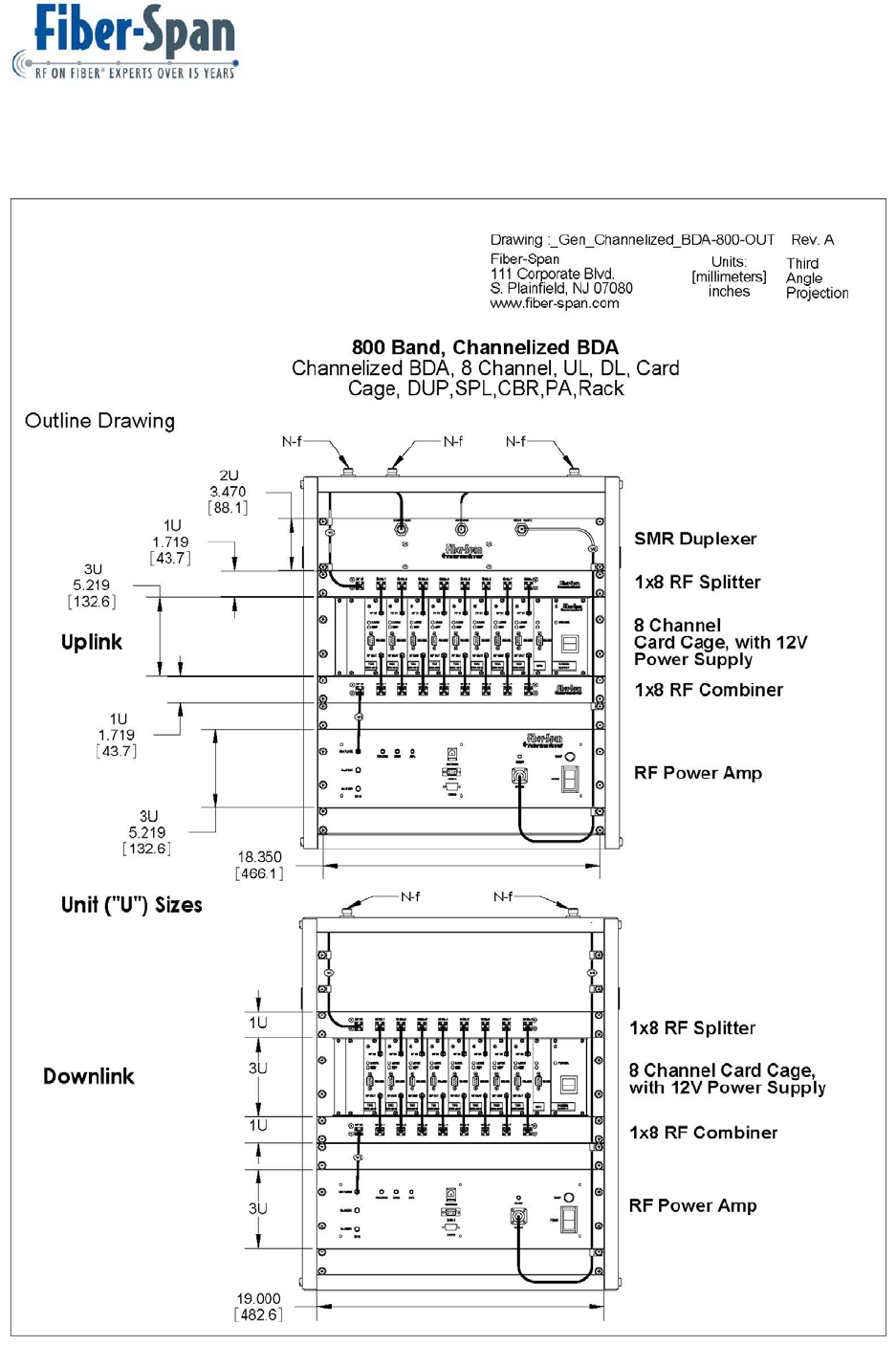
12 Outline Drawing

FS51C-85-USR
User Manual Ver. B
Document ID: FS51C Page 18 of 23
13 Troubleshooting
Problem 1: No RF Output Signal from the Power Amp.
Solution 1a: Confirm Input and Output RF cable into the Power Amp are not kinked or broken.
Solution 1b: Check the “Enable” alarm wire harness from the TCC Card Cage is wired to the
rear of the Power Amp alarm input.
Problem 2: No RF signal level output from the RF Combiner.
Solution 2a: The RF Combiner has internal active components, confirm it is powered by +12
Volts from the Card Cage output voltage header in the rear panel.
Solution 2b: The RF Combiner has in-line external RF cable connections. The common port
that goes into the Power Amp and 8 Input RF cable one for each channel path. Check and
confirm the path in question has the RF cables properly secured , tested and are known to work
properly. Each RF Combiner channel path can be independently tested. See Figure 6 for detail
Test Point (TP) to assist in trouble shooting.
Problem 3: No RF Signal from the Trunked Channel Cards (TCC).
Solution 3a: Verify the TCC card has been inserted correctly in the track and is secured and
keyed to the back panel header.
Solution 3b: Verify the Card Cage power supply is “On”. The Power supply has a visual
indicator to confirm it is On.
Solution 3c: See the Operational Manual FS51C-xx-SFT1, Run the program and read the
channel frequency to confirm it is the correct corresponding frequency. If not the desired
channel frequency, write the corresponding frequency. For additional information see the
diagnostic software mentioned above.
13.1 RF Level Measurements
When the RF Levels are not meeting specifications, each section from within the Cluster can be
diagnosed to determine the root cause of the failure.
RF test equipment is required to troubleshoot the Channelized BDA:
1. A signal generator used as a source.
2. A RF spectrum analyzer to view the RF output signal(s).
3. Optional Pad(s). Used when source RF levels cannot be adjusted to optimum levels or
to prevent exceeding the RF input levels to the spectrum analyzer.
FS51C-85-USR
User Manual Ver. B
Document ID: FS51C Page 19 of 23
4. 3 RF cables (1 meter length), N-female to N-female. Match one end connector to the
equipment you are using.
5. Software
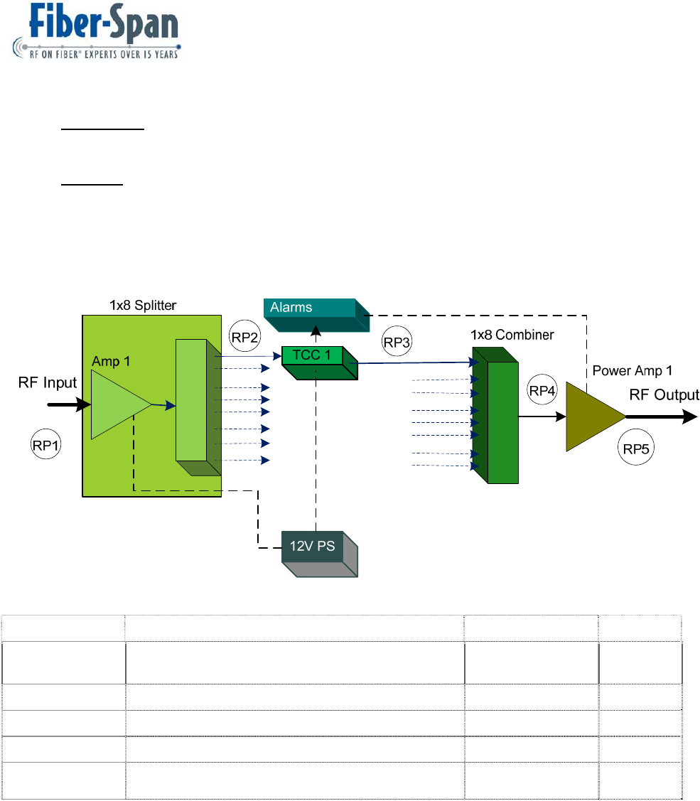
13.2 One-Channel (Path) Ch-BDA Block Diagram
Figure 5 shows 1 Channel path mapping to assist problematic TCC card and the associated
products within the Cluster and PA.
Figure 5
Reference Points Description RF Level(s) range Units
(RP1) Main RF Input to the Cluster RF Splitter. Confirm
reference signal present. -80 thru -20 dBm
(RP2) RF Input to TCC Card 1. -70 thru 0 dBm
(RP3) RF Input to Combiner. -38 +/- 2 dBm
(RP4) RF Input to PA. -25 +/- 2 dBm
(RP5) Main RF Output of PA 30 +0/-1 dBm
Composite
FS51C-85-USR
User Manual Ver. B
Document ID: FS51C Page 20 of 23
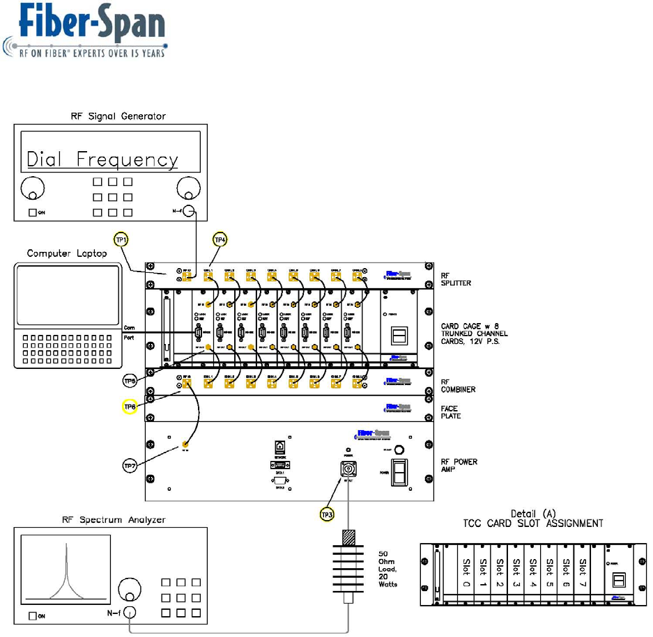
Figure 6
Figure 6 illustrates an 8 Channel BDA with the Test Equipment Setup (TES).
Most analyzers can accept a 20dBm composite RF input signal level. However, Fiber-Span
recommends verifying the specifications of your analyzer prior to connecting it to the PA Output
port.
Set the signal generator and spectrum analyzer to the center frequency of the downlink or uplink
frequency spectrum.
Set the RF output level of the signal generator to -80dBm. Connect the Spectrum Analyzer to
the “In-Line” 20dB PAD that connects to the PA Output; turn “On” the Spectrum Analyzer. Turn
“On” the Device Under Test (DUT). Make sure the RF Splitter and RF Combiner are “On” and
connected to the rear panel of the 3U Card Cage Power Header. Run the software, set the
sensitivity to Key “On” at -80. See the FS51C-xx-SFT1, User Manual also included for
additional instructions for setting the frequency and threshold values.

FS51C-85-USR
User Manual Ver. B
Document ID: FS51C Page 21 of 23
When all of the Cluster section functions properly, confirm all the RF cables are not faulty that
interface and route the path in question.
14 FCC Required Statement
14.1 Manufacturer Notes
“Changes or modifications not expressly approved by the manufacturer could “Void” the user’s
authority to operate the equipment”.
This equipment has been tested and found to comply with the limits for a Class A digital device,
pursuant to Part 15 of the FCC Rules. These limits are designed to provide reasonable
protection against harmful interference when the equipment is operated in a commercial
environment. This equipment generates, uses, and can radiate radio frequency energy and, if
not installed and used in accordance with the instructions manual, may cause harmful
interference to radio communications. Operation of this equipment in a residential area is likely
to cause harmful interference in which case the user will be required to correct the interference
at his own expense.
This device has been designated to operate with the antennas having a maximum gain of [9]
dBi for a 1 meter distance and antennas having a gain greater than [15] dBi are strictly
prohibited for use with this device. The required antenna impedance is [50] ohms.”
Equipment manufacturers shall provide proper values of x and y to comply with the applicable
RSS.
To improve and correct equipment performance the following can be performed:
1. Reorient or relocate the receiving antenna.
2. Increase the separation between the equipment and receiver.
3. Connect the equipment into an outlet on a different circuit from that to which the receiver
is connected.
4. Consult the dealer or an experienced radio/TV technician for help.

FS51C-85-USR
User Manual Ver. B
Document ID: FS51C Page 22 of 23
15 Glossary
The following is a list of abbreviations and terms used throughout this document.
Abbreviation/Term
Definition Definition
AGC Automatic Gain Control
ALC Automatic Level Control
BA Booster Amp
BB Broad Band
BDA Bi-Directional Amplifier
CA Coverage Antenna
CBR Combiner
CCC Card Cage Cluster
DA Donor Antenna
DAS Distributed Antenna System
DL Downlink
DUP Duplexer
DUT Device Under Test
GPS Global Positioning System
HW Hardware
IF Intermediate Frequency
LNA Low Noise Amp
LO Local Oscillator
MC Micro Controller
OPM Operational Product Manual
PA Power Amp
PLL Phase Locked Loop
PS Power Supply
RF Radio Frequency
RSR Rack Space Required
RSSI Receive Signal Strength Indicator
SPL Splitter
SW Software
TCC Trunked Channel Cards
TCO Time Clock Oscillator
TES Test Equipment Setup
TP Test Point
UL Uplink
V Volts
VSWR Voltage Standing Wave Ratio

FS51C-85-USR
User Manual Ver. B
Document ID: FS51C Page 23 of 23
16 Warranty Information
The RRU carries a standard warranty period of one (1) year unless otherwise indicated on the
shipping package or noted in the purchase order agreement.
16.1 Warranty Limitations
The warranty is limited to the repair or replacement of the defective product. Fiber-Span will
decide which remedy to provide for defective components at its own discretion. Fiber-Span
shall have a reasonable time after determining that a defective product exists to repair or
replace the problem unit. The warranty applies to repaired or replaced products for the balance
of the applicable period of the original warranty or ninety (90) days from the date of shipment of
a repaired or replaced component, whichever is longer.
The Fiber-Span standard warranty does not cover products which have been received
improperly packaged, altered, or physically damaged. For example, broken warranty seal,
labels exhibiting tampering, physically abused enclosure, broken pins on connectors, any
modifications made without Fiber-Span authorization, will void all warranty.
16.2 Limitations of Damages
The liability for any defective product shall in no event exceed the purchase price for the
defective product. Fiber-Span has no liability for general, consequential, incidental or special
damages.
16.3 Return Material Authorization (RMA)
No product may be returned directly to Fiber-Span without first getting an approval from Fiber-
Span. If it is determined that the product may be defective, you will be given an RMA number
and instructions in how to return the product. An unauthorized return, i.e., one for which an
RMA number has not been issued, will be returned to you at your expense. Authorized returns
are to be shipped to the address on the RMA in an approved shipping container. It is suggested
that the original box and packaging materials should be kept if a defective product needs to be
shipped back to Fiber-Span. To request an RMA, please call 908-754-0646.