Fidelity Comtech FCI2400 Wireless LAN System with Amplifier User Manual Amp Users Manual pdf
Fidelity Comtech, Inc. Wireless LAN System with Amplifier Amp Users Manual pdf
Users Manual Revised
The following is a preliminary User’s Manual demonstrating the basic content included
in the User’s Manuals of all systems to be sold by Fidelity Comtech, Inc.
This particular manual relates specifically to the FCI-2401 system with an antenna of
choice. The final page of the User’s Manual is to be removed and posted by the
Professional Installer at the location of installation, thus notifying the end user of Heath
Hazard and Professional Installation requirements.

FCI-2401 Intelligent Amp
A 4 in 1 Bi-Directional Amplifier
with Automatic Gain Control
Installation & Configuration
Guide
Fidelity Comtech, Inc.
5485 Conestoga Court, Suite 237zBoulder, Colorado 80301
Phone - 303.786.8048 z Fax - 303.415.1113
www.fidelity-comtech.com z email: info@fidelity-comtech.com
NOTE: This Guide is intended for use by
Professional Installation personnel
2Fidelity Comtech, Inc. Proprietary Information 30414
Copyright ©2003
by Fidelity Comtech, Inc.
All Rights Reserved. No part or parts of this document may be reproduced,
translated, stored in any electronic retrieval system, or transmitted, in any
form or by any means, electronic, mechanical, photocopying, recording, or
otherwise, without the prior written permission of the copyright holder.
3
Fidelity Comtech, Inc. Proprietary Information 30414
TABLE OF CONTENTS
PRODUCT DESCRIPTION ..................................... 4
PACKAGE CONTENTS ........................................... 4
TYPICAL INSTALLATION ....................................... 5
DC Power Injector Connections and Indicators. 6
FCI-2405 Intelligent Amp Connections
and Indicators ................................................ 7
LED Settings: Selecting Signal Output Power.. 7
OPERATION .............................................................. 9
SPECIFICATIONS ..................................................... 9
FUNCTIONAL BLOCK DIAGRAM ......................... 10
SAFETY NOTICE ....................................................... 10
LIMITED WARRANTY .............................................. 11
WARRANTY NOTICE ............................................... 11
INSTALLATION TIPS ............................................... 12
APPENDIX A: Infrared (IR) Link
Configuration Instruction .................................. 13
APPENDIX B: FCC Part 15 Certified Systems ........ 15
4Fidelity Comtech, Inc. Proprietary Information 30414
PRODUCT DESCRIPTION:
The Fidelity Comtech FCI-2401Intelligent Amp is a 4 in 1
bi-directional amplifier with Automatic Gain Control that
allows the extension of operating range in 802.11(b) wire-
less environments. The FCI-2401 provides four (4) select-
able output signal settings of 100 mW, 250 mW, 500 mW
and 1 Watt configurable via an integrated IR link. The bi-
directional amplifier incorporates integrated intelligence
capabilities that sense the input power and automatically
maintains the appropriate output power regardless of cable
loss. This automatic gain adjustment minimizes the signal
distortion so that the desired signal quality can be assured.
In wireless applications where longer operating range
requires signal amplification the FCI-2401 Intelligent Amp
will automatically adjust to accommodate for cable and
connector loss regardless of length or configuration. With
a ruggedized design the FCI-2401 will operate within a
temperature range of –40 C to +85 C assuring the desired
performance regardless of the installation environment.
PACKAGE CONTENTS:
An outdoor ready amplifier unit
DC power injector unit
AC power adapter
User Manual with Warranty information

5
Fidelity Comtech, Inc. Proprietary Information 30414
PROFESSIONAL INSTALLATION REQUIRED
The FCI-2401 Intelligent Amp must be installed by experienced
antenna installation professionals who are familiar with radio fre-
quency (RF) issues such as gains and losses, as well as local build-
ing and safety codes. Failure to do so will void the product war-
ranty and may expose the end user to excessive RF hazards. Regu-
lations regarding maximum antenna gains, amplifier power gain
and maximum permissible exposure vary from country to country.
It is the responsibility of the end user to operate within the limits of
these regulations and to ensure that the professional installers ad-
here to the antenna installation instructions contained in this manual
and comply with RF exposure regulations for transmitter operat-
ing conditions. All antennas are intended to be installed outdoors.
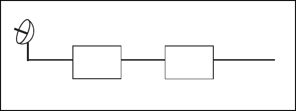
TYPICAL INSTALLATION:
As shown in the diagram (Diagram 1) below, the FCI-
2401 Intelligent Amp components are placed in line
between the antenna and wireless equipment. The
power for the FCI-2401 Intelligent Amp is carried to the
amplifier from a DC Power Injector via RF cable. The
DC Power injector is an indoor unit and requires
weather protection. The amplifier is weatherproof and
has been designed to withstand the outdoor environ-
ment ranging from –40 C to +85 C. With the integrated
lightning protection the amplifier unit must be grounded.
6Fidelity Comtech, Inc. Proprietary Information 30414
CAUTION:
The cable between the DC Power Injector and the
Intelligent Amp carries 9 V DC power, make sure it
is NOT shorted to ground. If the LED on the DC
Power Injector does not light when power is con-
nected (the transformer is connected) check for DC
short in the RF cable.
DC Power Injector Connections and Indicators:
The DC injector injects DC power into the RF cable and
the power is carried to the FCI-2401 Intelligent Amp with
the RF signal. The power supply provided is a 110 AC
to 9V DC converter.
Diagram 1: Typical Installation
FCI-2401
Amplifier To wireless
equipmen
t
RF
Cable
RF
Cable
RF
Cable
Antenna
DC Power
Injector
7
Fidelity Comtech, Inc. Proprietary Information 30414
“RADIO” Connection:
This “N” connector is connected to the wireless radio
equipment via RF cable.
“AMPLIFIER” Connection:
This “N” connector is cabled to the FCI-2401 Intelligent
Amp via the appropriate RF cable.
FCI-2401 Intelligent Amp Connections and
Indicators:
“INPUT” Connection:
This “N” connector is connected to the DC Power Injector
via the transmission cable.
“Antenna” Connection:
This “N” Female connector connects to the antenna with an
appropriate length of coax cable.
LEDS: The LEDS indicate the current output power
settings.
LED Settings: Selecting Signal Output Power
[NOTE: Only Professional Installers are allowed to set or change the output
power on the amplifier. Once these settings are established, the amplifier
unit must be installed in a manor that the end user is prevented from
modifying the configuration].
When power is applied one of the four (4) output power
indicator LEDs will light.
To make changes to the power settings follow instructions
below:
8Fidelity Comtech, Inc. Proprietary Information 30414
The Signal boost can be set two ways:
2) If the installer does not want to open the case it is
possible to set the output power through the infrared
(IR) port. See Appendix A for instructions.
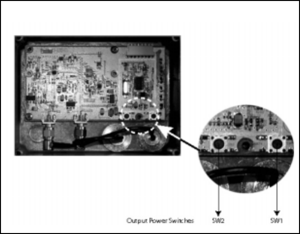
1) Take out the four (4) Philips head screws and re-
move back cover, being careful not to lose the neo-
prene O ring gasket around the screws. With power
applied to the amplifier, press SW1 or SW2 (as
shown in Figure 1) until the desired output power
LED lights.
Figure 1:
Looking inside the FCI-2401Intelligent Amp (back cover removed)

9
Fidelity Comtech, Inc. Proprietary Information 30414
OPERATION:
It may take several seconds for the FCI-2401 to
sense and accurately determine the input power level.
Once the input power is established the unit will
automatically maintain a stable output power. The
FCI-2401 Intelligent Amp contains a high perfor-
mance power detector and directional coupler. It
senses the input power and switches to transmit
mode in less than 60 ns (the best performance cur-
rently available). The remainder of the time the FCI-
2401 is in receive mode. The signal level must be
greater than 2 mW to turn the transmitter on as it is
designed to work with both Direct Sequence Spread
Spectrum (DSSS) and Frequency Hopping Spread
P
ARAMETERS
S
PECIFICATIONS
egnaRycneuqerFzHM4842ot0042
niaGevieceR ecnamrofrepmumitponiatniamotstsujdA.mumixamBd02
erugiFesioNevieceRBd0.3<
niaGtimsnarTrewoptuptuoniatniamotstsujdayllacitamotuA
leveLlangiSmuminiMmBd01
leveLlangiSmumixaMmBd52
rewoPtupnICDcdV42ot7
rewoPtuptuOttaW1,Wm005,Wm052,Wm001;elbatceleS
egnaRerutarepmeTgnitarepOsuisleC58+otsuisleC04-
snoitcennoCsrotcennoCN
SPECIFICATIONS:
10 Fidelity Comtech, Inc. Proprietary Information 30414
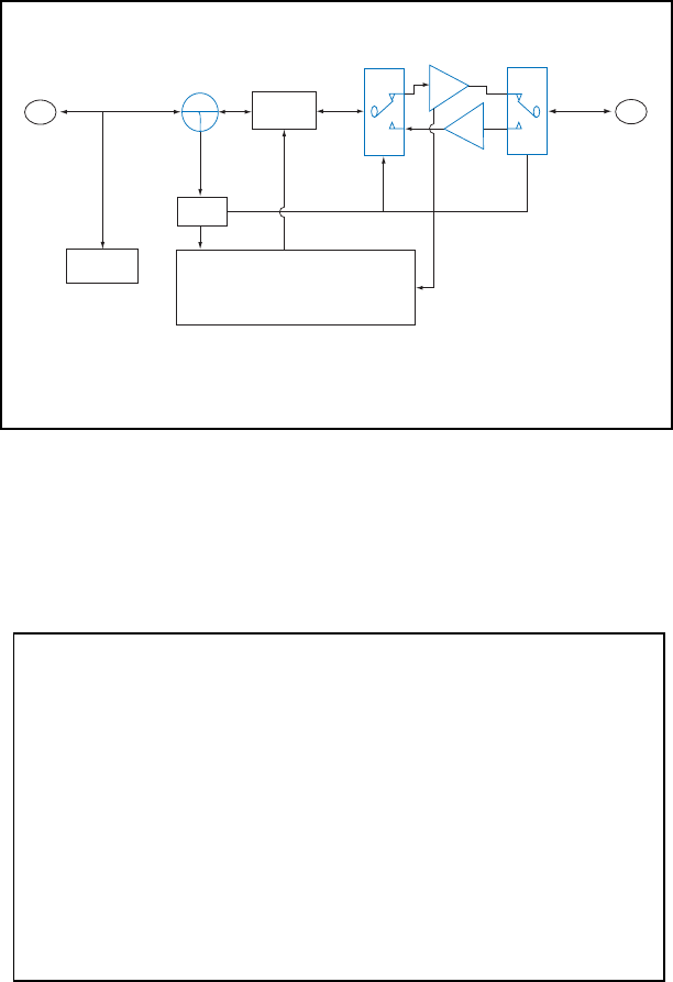
FUNCTIONAL BLOCK DIAGRAM:
POWER
SUPPLY
From
XCVR
PWR
SENSE
ATTEN
CONTROL CPU
T/R
Switch
T/R
Switch
PA
LNA
To
Antenna
2.4 GHz Remote Amplifier Block Diagram
T/R
Antenna
Connecto
r
Input
Connector
PWR
Sense
ATTEN
CTL
..
SAFETY NOTICE
This equipment complies with FCC radiation exposure limits
set forth for an uncontrolled environment when installed as
directed. When this device is installed as a fix-mount applica-
tion there is a minimum required separation distance of one (1)
meter between the antenna and all persons during normal
operation. For mobile mounted antennas, the required separa-
tion distance is a minimum of twenty (20) cm between the
antenna and all persons during normal use.

11
Fidelity Comtech, Inc. Proprietary Information 30414
LIMITED WARRANTY
Fidelity Comtech, Inc. warrants that this device is free of defects in
material and workmanship for a period of one (1) year after initial
purchase. Fidelity Comtech will, in this period of time, repair or
replace, any FCI-2401 Intelligent Amp product returned to the
factory, freight prepaid.
The Fidelity Comtech warranty covers repairs or replacement (at our
option) of the product only. Fidelity Comtech is not responsible for the
cost of removal, reinstallation or shipping to the place of repair.
Fidelity Comtech does not extend or modify its warranty period as a
result of repair or replacement.
Fidelity Comtech reserves the right to void a warranty and/or make
reasonable charges for repair of a unit if the warranty seal is broken
or the unit displays evidence of misuse, abuse or tampering.
Fidelity Comtech is not responsible for damage to any other equip-
ment or property, or any other consequential or incidental damages of
any kind, whether based on contract, negligence, or strict liability.
Maximum liability shall not in any case exceed the purchase price of
the unit.
Warranties give you (the buyer) specific legal rights. You may also
have other rights that vary from state to state. This warranty is only
extended to purchases made in the United States of America or its
possessions.
WARRANTY NOTICE
The FCI-2401 Intelligent Amp warranty is null and void if any of the
following occurs:
1. The antenna connections are not properly waterproofed.
2. Improper connectors are used.
12 Fidelity Comtech, Inc. Proprietary Information 30414
INSTALLATION TIPS:
The FCI-2401 unit should be mounted as near the antenna as possible
in order to eliminate any cable loss between the radio and the an-
tenna. From this position the unit will provide full output from the
antenna.
When mounting the amplifier unit the N-connectors should face in the
downward direction in order to minimize the impact of any possible
moisture.
13
Fidelity Comtech, Inc. Proprietary Information 30414
APPENDIX A: Infrared (IR) Link
Configuration Instructions
Overview:
It is possible to set the output power of the FCI-2401 amplifier
without opening the weatherproof seal. This feature is espe-
cially useful for installers who may need to install these devices
frequently.
IR programming of the FCI-2401 amplifier is performed through
the IrDA port of a Palm Pilot PDA. Programming is limited to
setting the correct output power
Setup
Download the program “Pocketerm II.” This program is avail-
able from www.palmgear.com. Follow the instructions to install
this program in your palm pilot. This program is free for the
first 30 days. After 30 days, there is a small use fee.
Once the program has been installed, follow this process to
configure Pocketerm II and establish communications with the
FCI-2401amplifier:
1. Pull down the main menu
2. Under “Options -> COMM” press “Configure”
3. Set the serial options to: 8 data bits, 9600 baud, 1 stop bit,
No parity, no flow control, and most importantly, check the
box that says “USE IR”. Press “OK” Press “OK” again at
“COMM options.”
4. In the upper right hand corner of the screen, tap the button
marked “Connect”.
The IR link serves as a way to communicate with the amplifier
in the FCI-2401, but is not intended to provide a long distance
link. It can easily be confused by direct sunlight and it is
necessary to hold the palmpilot within about 6” of the amplifier
to achieve a reliable connection. Most installers find it benefi-
cial to set power prior to installing the amplifier.
14 Fidelity Comtech, Inc. Proprietary Information 30414
Setting the output power
If power is applied to the bi-directional amplifier while a palm
pilot is monitoring the IR port, the user will observe “Booster
amplifier vX.X” which indicates the software release.
Using either the pop-up keyboard or the graffitti, the user can
enter the digit “1” through “4”, to send a message to the ampli-
fier through the IR link. The user will be prompted with a
message similar to “Confirm set power to 500 mW?” If this is
correct, press “y” on the keyboard, or enter the graffitti stroke
for “y”. The amplifier will respond by setting the output LED to
the new value and sending the following message over the IR
link: “Power set to 500mW.”
If the installer waits more than 10 seconds before pressing “y”
to confirm the new power setting the request to change power
times out, and the amplifier assumes it received a spurious
input on the IR port. This is to prevent the amplifier from
accidentally reconfiguring its power to a value lower than that
required to maintain a suitable link.

15
Fidelity Comtech, Inc. Proprietary Information 30414
APPENDIX B: FCC Part 15 Certified Systems
FCC Certified systems consist of:
* FCI-2401 amplifier, DC Power injector and 9V power adapter
* Orinoco WLAN card: FCC ID: IMRWLPCE24H
* Outdoor Antenna
Orinoco certified antennas:
NOTE: The 13 dBi and 19 dBi panel antennas are only authorized
for use in point to point systems. It is the installer’s responsibility
when using these antennas to ensure that the system is used exclu-
sively for point to point operations, and that the antenna may not be
co-located with other intentional radiators transmitting the same
information. Reference FCC regulations 15.247(b)(3).
This device and its antenna must not be co-located or operating in
conjunction with any other antenna or transmitter
ledoM rewoP
sgnitteS
deifitreC
slennahC noitallatsnI
DARXAM
inmOiBd4
80042BFM
Wm001
Wm052
Wm005
ttaW1
11-10slennahC
11-10slennahC
01-30slennahC
60lennahC
dexiFroeliboM
noitallatsnidetnuoM
sseleriWCRA
lenaPtalFiBd31
Wm001
Wm052
Wm005
ttaW1
11-10slennahC
90-30slennahC
60lennahC
a/n
detnuoMdexiF
ylnosnoitallatsni
sseleriWCRA
lenaPtalFiBd91
48000-IAA
Wm001
Wm052
Wm005
ttaW1
80-40slennahC
60lennahC
a/n
a/n
detnuoMdexiF
ylnosnoitallatsni

Important Information for the User
Your wireless system has been installed and configured by an RF profes-
sional to comply with FCC part 15 regulations. These limits are designed to
provide reasonable protection against harmful interference when the
equipment is operated in a commercial environment. This equipment
generates uses and can radiate radio frequency energy and, if not installed
and used in accordance with the installation and configuration manual, may
cause harmful interference to radio communications. Operation of this
equipment in a residential area is likely to cause harmful interference in
which case the end user will be required to correct the interference at their
own expense.
Modifications to this system including changing antenna, power setting or
transmit channel may result in a non-compliant system, and should only be
undertaken by professional installers after reading the Installation and
Configuration guide for this system.
For further information, please contact:
Fidelity Comtech Customer Support
5485 Conestoga Court, Suite 237
Boulder, CO 80301
e-mail: info@fidelity-comtech.com
Installer: Please post this notice in a prominent location near the amplifier
SAFETY NOTICE
This equipment complies with FCC radiation exposure limits
set forth for an uncontrolled environment when installed as
directed. When this device is installed as a fix-mount applica-
tion there is a minimum required separation distance of one (1)
meter between the antenna and all persons during normal
operation. For mobile mounted antennas, the required separa-
tion distance is a minimum of twenty (20) cm between the
antenna and all persons during normal use.