Field Controls Electronic Steam Unit Power S2000 Users Manual
SC100 S2000-install
S2000 to the manual fe7d1416-4ecf-41cd-8fbe-2d2cf2250161
2015-02-02
: Field-Controls Field-Controls-Electronic-Steam-Unit-Power-S2000-Users-Manual-427539 field-controls-electronic-steam-unit-power-s2000-users-manual-427539 field-controls pdf
Open the PDF directly: View PDF ![]() .
.
Page Count: 16
MODELS S2000 AND S2020
FOR GAS OR OIL FORCED AIR FURNACES, HEAT PUMPS AND ELECTRIC FURNACES
has been designed to be simple to Install, Operate and Maintain.
Read this manual before you install the Humidifier.
Parts included in the Steam Humidifier package are:
1. Self Piercing Saddle Valve
2. Installation Instructions and Owners Manual
3. Mounting Templates x2
4. Installation Hardware package
5. Insulation and tape
6. Automatic Drain Assembly
7. Humidistat - Model #062000 or 072000
8. 1/2” I.D. Drain Hose-8 FT.
9. Anode #Z100
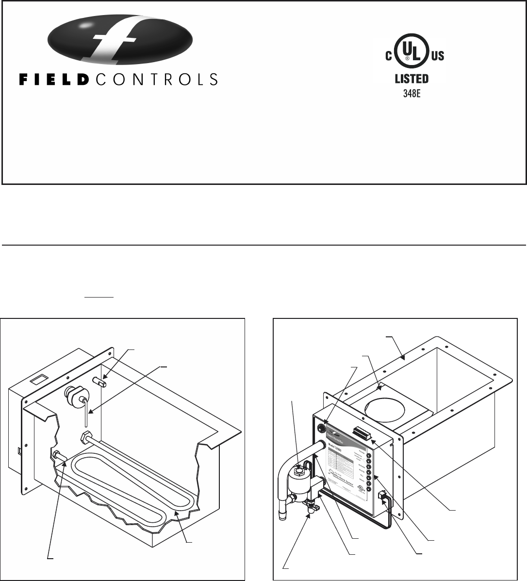
Familiarizing yourself with the items listed in Figures 1
and 2 will assist you in installing and maintaining your
Steam Power Humidifier. This product should be installed
according to local and national codes and standards.
Options and additional parts recommended:
1. Water Hammer Arrester #WH 100
2. Anode #Z100
3. Decorative Under Duct Cover # SC100
4. Gasket Material to seal flanges (field provided)
5. Model APD Current Sensing Switch, Sail Switch or
other Airflow Proving Device.
6. WFA-195 Water Filter Assembly
WATER INLET
WATER LEVEL
PROBE
HEATER
TEMPERATURE PROBE
FIG. 1
For Replacement Parts Call (800) 446-3110
09021A0118
U.S. PATENT NUMBER 5758 018
serial number
Ewc
385 Highway 33, Englishtown, NJ 07726
CONTROLS, INC.
UL
®
CUS
LISTED 141V
POWER
DRAIN
FILL
HEATER
BLOWER
Thermistor
Heater
Water
Suitable for Residential Use Only
Model S2020
Steam Humidifier
2.0 KW 240 Volt 8.3 Amps
FIG. 2
MANUAL WATER DRAIN
WATER PAN
TANK BAFFLE
BLOWER
INTERLOCK &
HUMIDISTAT CONN.
AUTO DRAIN CONN.
"T" ADAPTER
STATUS LIGHTS
OVERFLOW
FOR DRAIN
VALVE DETAILS
See Page 12
WATER INLET
This symbol on
the product means
the product is
listed by
Underwriters
Laboratories, Inc.
1
®
Copyright © 2011 Field Controls All Rights Reserved.
The Residential Power Humidifier you have purchased
FIELD CONTROLS ELECTRONIC STEAM UNIT - POWER HUMIDIFIER
P/N 090375A0227 Rev. M
10/2011
&
Instructions
Owner's
Manual
Installation
SIMPLIFIED INSTALLATION INSTRUCTIONS
DETAILED INSTALLATION INSTRUCTIONS
1. Insulate the water reservoir. See figure 3.
2. Select the mounting location on the duct and tape
on the mounting template.
3. Drill the (8) 1/8" mountings holes.
4. Cut out the humidifier opening in the duct.
5. Insert the humidifier into the opening and screw in
place.
6. Flush and connect the water line.
7. Connect the drain line.
8. Make 24 VAC electrical connections to achieve fan
operation and interlock circuit.
9. Install and connect the humidistat.
10. Plug power cord into a grounded dedicated 120 VAC, 20
amp outlet for S2000 (240 VAC, 15 amp for S2020).
1. INSULATE WATER TANK RESERVOIR
2. LOCATION-LOCATION - Required Criteria
4. MOUNTING TEMPLATE
5. DRILL HOLES AND CUT OPENINGS
With insulation foil side down, remove adhesive backing.
Align humidifier so that front side of unit meets long edge of
insulation. Fold insulation up onto sides of humidifier and
press firmly. Apply 5 continuous strips from the tape
provided to seal the foil as shown. The tape will prevent the
sharp duct edges from damaging the foil. Use additional foil
tape to repair damage to the foil. The Insulation MUST be
applied to the tank regardless of the mounting location.
DO NOT INSTALL this unit in an attic period. Do Not
Install this unit in any area that may fall below 35
degrees F. Doing so will void your warranty! The steam
humidifier can be installed in either the warm air supply or the
cold air return ducts; however the preferred location would be
in the warm air supply duct of the system. This humidifier does
not require warm air to evaporate the water in order to provide
humidity, but it will operate more efficiently in the warm air duct
and condensation is less likely to occur on the surrounding cold
surfaces. Efficiency is lost in a return air duct location.
When selecting a location on the duct, be certain that there is
enough room in the duct for the water reservoir. There should be
at least five (5) inches above the reservoir and the reservoir
should not occupy more than about 25 percent of the duct space.
If this criteria can not be met, you should install the unit under
the duct by means of the tank flange. See page 6.
If a suitable means of gravity draining the unit is not available
or cannot be provided, the unit will work with the drain valve
electrically disconnected. Call the Technical Support Hotline
for Instructions.
It is highly recommended but not required that the
use of Fiberglass duct-board with this product
includes an anti-microbial treatment.
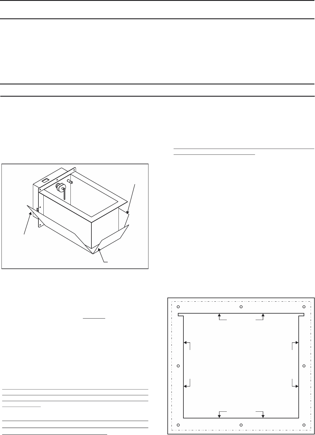
Providing Adequate Structural Support for this unit is the
responsibility of the Installer. It is recommended to
reinforce the cut openings with folded lengths of sheet-
metal to provide rigidity to the duct opening. Now the
screws must pass through 3 layers of metal when inserted.
DO NOT install this unit into fiberglass duct without
adequate structural support! Both models weigh
approximately 9 lbs. empty and 15lbs. full of water.
Two mounting templates are provided. Choose the correct
template for your mounting method. Tape the mounting
template to the duct. The template must be leveled using the
top of the cutout on the template. The template should be
located so that the bottom of the reservoir cut-out is flush with
the inside of the bottom of the duct for horizontal duct. Since
most ducts are insulated this additional space, about one (1)
inch, must be accounted for when determining the location
for the bottom of the reservoir cut-out. If you are mounting it
under the duct, make sure the duct is level.
Use an electric drill, with grounded power cord, to drill eight
(8) mounting holes, 1/8" diameter, in the duct. These can be
drilled through the template at the locations indicated on the
template.
A saber saw or tin snips can be used to cut out the water
reservoir opening.
Insert and/or mount the Humidifier and secure it to the duct
with the provided screws.
2
FIG. 4
MOUNTING TEMPLATE
MODEL S2000 & S2020
1. TAPE TEMPLATE IN LEVEL POSITION.
2. DRILL (8) HOLES FOR SHEET METAL SCREWS
SHOWN ON TEMPLATE (DO NOT DRILL LARGER
THAN 1/8" DIAMETER.
3. CUT OUT SOLID LINE AREA AS MARKED.
4. MOUNT HUMIDIFIER PER INSTRUCTIONS.
CUT ON LINE
CUT ON LINE
CUT ON LINE
CUT ON LINE
P/N 094021B0037
3. WEIGHT - Required Criteria
USE TAPE TO SEAL THE FOIL
TO THE FRONT MOUNTING PLATE
(3 PLACES-SIDES AND BOTTOM)
INSULATION
(FOIL SIDE OUT)
USE TAPE TO SEAL
THE OUTSIDE EDGE
OF THE FOIL
(2 PLACES)
FIG. 3
6. WATER SUPPLY - Required Criteria
9. WIRING THE STEAM HUMIDIFIER
7. M OUNTING THE STEAM HUMIDIFIER
8. STEAM OPERATION - Required Criteria
A. WATER SUPPLY USING THE SADDLE VALVE
FURNISHED WITH UNIT. Important! See page 14.
A. INSTALLING AND WIRING THE HUMIDISTAT
B. OVERFLOW & DRAIN LINES - Required Criteria
Installation instructions for the saddle valve are printed on the
plastic bag containing the saddle valve and its components.
Tap into a 1/2” or 3/4” domestic cold water line. Avoid
connecting to water lines from a Reverse Osmosis system or
De-ionized water systems. The supply water must read a
minimum of 25 ppm in order for the Steam unit to reliably
sense the water.
NOTE: Never install the saddle valve on the bottom of the
water pipe. Sediment in the water pipe may clog the saddle
valve. Flush the line before connecting to the unit.
tightening the hex compression nut, tighten only enough to
assure there are no leaks.
NOTE: Saddle valves do not meet plumbing codes in some
areas. A “T” fitting with a valve may be required to meet code
or, if low water pressure causes frequent water alerts on the
steam humidifier. NOTE: Flush the new water line before
connecting it.
NOTE: The use of City water or Municipal water is preferred.
Softened water is preferred over untreated well water. Specify
the Optional WFA-195 disposable water filter for treating
any water supply that is very high in mineral content.
NOTE: Use a water hammer arrester (WH-100) if water
spikes occur (pipes bang)during fill ups.
When
A temperature sensor is mounted in the water reservoir of the
humidifier. As the water temperature increases to about 170
degrees F, the computer closes a set of blower relay contacts to
start the system fan. When the water cools to about 140 degrees
F, the computer will open the relay contacts to shut off the fan.
This operational sequence drastically decreases the chances of
condensation occurring inside the duct-work.
A humidistat, such as the Model #072000 is required to control
the Steam Humidifier. The humidistat may be installed on the
wall in the living space or on the return air duct. NOTE:
Continuos fan operation should be initiated if the humidistat is
installed on the return air duct! Instructions for installation are
packaged with each humidistat. Follow wiring instructions
carefully!
DO NOT connect any foreign voltage to the “H” terminals of the
humidifier! The Humidifier supplies it’s own control voltage.
Simply connect the two “H” terminals straight to any dry contact
humidistat terminals. If you are using a 3rd party Humidistat
that has powered terminals, you must use an isolating relay
to operate the Steam Humidifier. Failure to do so will result
in circuit board failure and will void all warranties.
Schematics on the following pages describe the suggested
interlock wiring arrangement for different HVAC systems.
Interlocking may be performed on systems that provide a 24vac
NEC Class 2 terminal block for system control.
AIR PROVING FEATURE: The Steam Humidifier has an
integrated air proving feature that allows the user to install a sail
switch and/or high humidity switch in the duct and easily
achieve fail safe shutdown in the event of fan/blower failure.
This feature prevents the Steam Humidifier from operating
unless adequate airflow is proven thereby avoiding a saturated
duct condition. WARNING: It is highly recommended to use
an airflow proving device. In particular Duct-Board
applications should always use an airflow proving device.
A factory jumper wire is provided and must be removed when
connecting the sail switch or other field supplied air flow
proving device. Leave the jumper in place if you decide not to
use the airflow proving feature.
IMPORTANT NOTE: If the Steam Humidifier is removed
and disconnected from the system, the blower interlock
circuit must be restored to it's original configuration. Failure
to do so may result in loss of blower operation during cooling
modes!
Use gasket material to seal where the front plate or tank flange
contacts the duct-work. Place the humidifier reservoir into the
opening in the duct and secure with eight (8) sheet metal
screws.
NOTE: If the duct-work will not support the unit in a level
position with the water pan full of water, the duct-work
must be reinforced. Both steam models weigh
approximately 9 Lbs. empty and approximately 15 Lbs.
when full of water.
Because of the high output of this Humidifier, it must not be
operated without the blower operating. The steam
humidifier is designed to be "Dominant" over the HVAC
System Blower. The "System" Blower will be operated by the
humidifier when the water tank temperature reaches 170
degrees F. A minimum of 800 cfm @ 800-900 fpm is required for
proper operation of the steam humidifier. Lower velocities may
result in excessive condensation inside the duct. See Air Proving
Feature on the next column! See Variable Speed on Page 7.
The use of an overflow line and drain line is always required.
Use the supplied 1/2” ID high temperature hose. Slip the hose
over the 1/2” OD “T” drain fitting and use a hose clamp to
secure. Route the hose to a suitable drain, avoiding kinks,
traps and sharp objects. DO NOT route the hose above the
humidifier. Failure to install all necessary drain lines may
result in water leaks during normal operating conditions,
and voids all warranties.
3
B. FIELD WIRING
IMPORTANT: Dedicated fused circuits and outlets of the
proper voltage and current ratings must be provided. Use a
NEMA 5-20R receptacle for the S2000 and a NEMA 6-15R
receptacle for the S2020. All wiring must conform to local and
national codes. Failure to do so will void all warranties.
DO NOT cut off the grounded plug and/or hard wire this unit to
line voltage! DO NOT use extension cords to operate this unit!
Doing so will void all warranties.
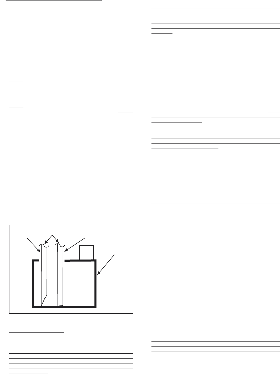
When routing the S2000 drain hose into a condensate pump,
be sure to cut the end of the hose at a sharp angle to prevent
the hose from bottoming out in the pan. It could result in
poor draining or no draining at all. Failure to do so may
result in water backing up into the S2000 reservoir and
eventual overflow. See Figure 5.
CORRECT INCORRECT
X
CONDENSATE
PUMP
DRAIN
HOSE
FIG. 5
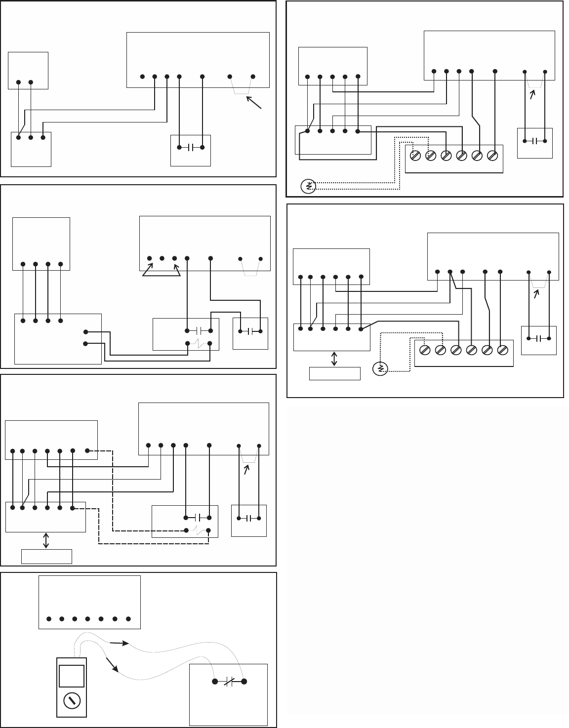
Typi ca l
Furnace
S2000 & S2020 Humidifier
Low Voltage Terminal Block
G1 R G2 H H
Heat only
Thermostat
WR
GWR
Heat Only System and
Steam Humidifier with standard
dry contact Humidistat
Dry Contact
Humidistat
A
A
FIG. 6
Factory
Jumper will
stay in place
unless a field
installed Air
Proving Device
is used.
FIG. 8
Bryant Evolution
Furnace
SPST Dry Contact
Isolating Relay
with 24vac Coil
G1 R G2 H H
C DBA
C DBA
Bryant/Carrier Evolution/Infinity
Variable Speed Heat/Cool System
A
A
Model APD or
Equivalent
S2000 & S2020 Humidifier
Low Voltage Terminal Block
2 4 v a c
Common
CONTROL WIRING SOLUTIONS FOR VARIOUS HVAC SYSTEMS
Additional diagram shown on page 7.
blower on the HVAC system does not operate when called
operating the blower on the HVAC system. If the Steam
Humidifier detects a loss of airflow longer than 1 minute, it will
shutdown the heating element and stop producing steam to
across the normally open contacts with the fan/blower running.
fan/blower is running.
062000 Humidistat
G1 R G2 H H A
A
S2000 & S2020 Humidifier
Low Voltage Terminal Block
Disconnect the wires from the “A”
terminals and check the device & circuit
with a reliable ohm meter. Check continuity
when the fan is off and when it is running.
Model APD current
sensing switch or
equivalent air proving
device. Dry Contacts Close
when fan is running!
00.3
OHM
FIG. 11
4
FIG. 7
Typical Furnace
G1 R G2 H H
Typical Thermostat
G YWR
G YWR
A
A
S2000 & S2020 Humidifier
Low Voltage Terminal Block
REMOVE
FACTORY
JUMPER
C
C
OD OD C RHH
Outdoor
Temperature
Sensor
072000 Humidistat
Refer to the 072000 Technical Bulletin
Model APD or
Equivalent
FIG. 10
Typical Air Handler
G1 R G2 H H
Thermostat with built-in
Humidification Control
G Y
W2
R
G Y
W2
R
Heat Pump System and Steam Humidifier with
Combo Thermostat/Humidistat
and Isolating Relay
A
A
S2000 & S2020 Humidifier
Low Voltage Terminal Block
REMOVE
FACTORY
JUMPER
C
HC
O
O
Outdoor Heat Pump
not shown for clarity
SPST Dry Contact
Isolating Relay
with 24vac Coil
Model APD or
Equivalent
HUM
Bryant
Evolution
Thermostat
DO NOT USE
Program Evolution
T-stat as follows:
1.Heating airflow
To Efficiency mode.
2.Humidifer
installed=Yes
3.Humidify with
Fan=Yes
4. Set FAN to
Continuous Mode &
select MEDIUM
speed.
NOTE: An APD or similar device
must be used in this application.
Wire the APD in series with the HH
circuit.
OD OD C RHH
Outdoor
Temperature
Sensor
072000 Humidistat
Refer to the 072000 Technical Bulletin
FIG. 9
Typical Air Handler
G1 R G2 H H
Typical Heat Pump
Thermostat
G Y
W2
R
G Y
W2
R
A
A
S2000 & S2020 Humidifier
Low Voltage Terminal Block
REMOVE
FACTORY
JUMPER
C
C
O
O
Outdoor Heat Pump
not shown for clarity
Model APD or
Equivalent
Leave Factory
Jumper in Place
Conventional Heat & Cool System
and Steam Humidifier with 072000
with 072000 Humidistat
Heat Pump System and Steam Humidifier
The latest improvement to the Field Controls humidifiers is the new
“Airflow Interlock Feature” provided on the low voltage terminal
block. Due to popular demand we have made it easier for you to
achieve fail safe lockout in the event the fan or blower on the
HVAC system does not operate when called upon. A high humidity
or airflow proving device is necessary.
You must still determine the type of proving device you want to
use. We recommend our new Model APD switch. But then all you
have to do is connect two low voltage wires from your air proving
device straight to the Steam Humidifier’s “A” terminals. No
additional field relays or components are needed.
The Steam Humidifier monitors the airflow circuit anytime it is
operating the blower on the HVAC system. If the Steam
Humidifier detects a loss of airflow longer than 1 minute, it will
shutdown the heating element and stop producing eam to avoid
saturating the duct.
You must test the air proving device when you install it to make
sure it will function properly. WARNING: DO NOT perform this test
with the wires connected to the Steam Humidifier. Temporarily
disconnect them. Refer to Figure 11.
1. After installing the air proving device, test for continuity across
the normally open contacts with the fan/blower off. You should
read infinity (no continuity) when the fan/blower is off.
2. Turn on the fan/blower at the thermostat and test for continuity
across the normally open contacts with the fan/blower running.
You should now read continuity (a complete circuit) when the
fan/blower is running.
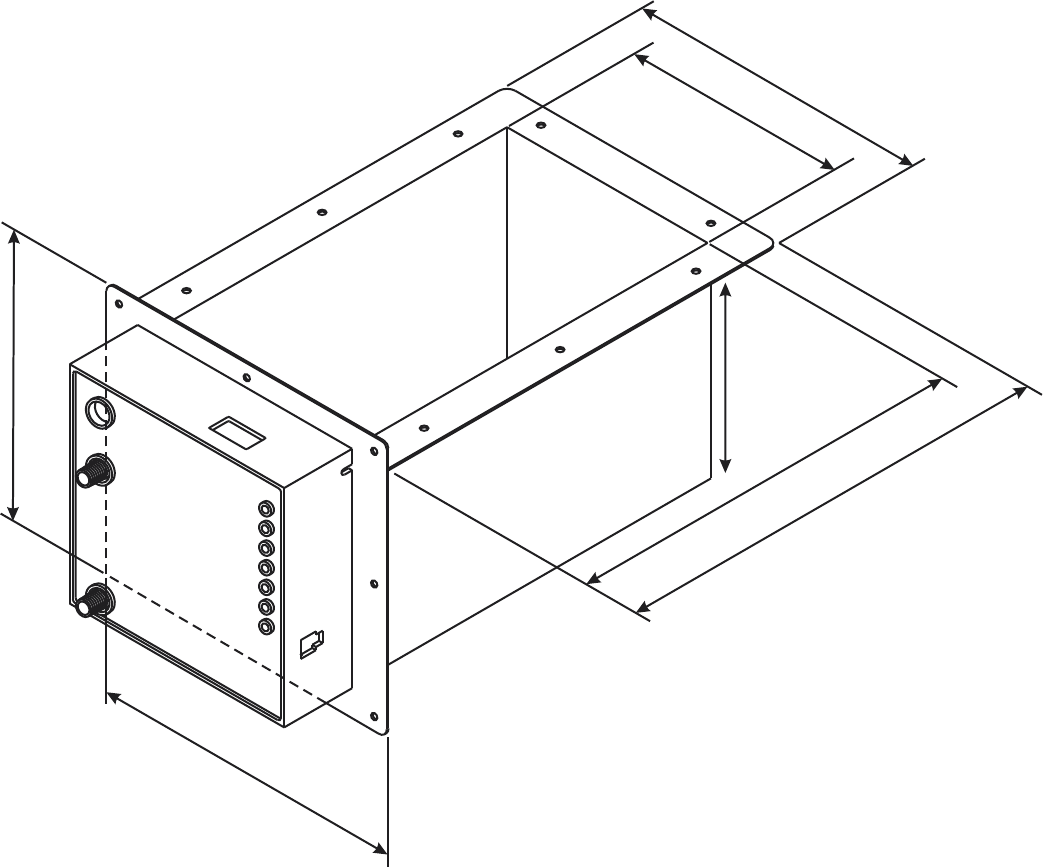
8.00”
6.00”
7.50”
8.25”
10.50”
11.60”
the room needed to install the unit in a certain location. The data can also be used to determine the minimum duct size the
Steam Humidifier can be inserted into. The Steam Humidifier should not obstruct more than 25% of the cross sectional area of
the selected duct. For Example: The humidifier tank measures 8 inches wide (including the flange) times the length of 11.6
inches=92.8 square inches. We are only concerned with the obstruction on a flat plane. Which is why the flange is taken into
account but not the depth of the tank. This assumes an up-flow configuration. If the configuration is horizontal, then the Steam
Humidifier will obstruct approximately 70 square inches of duct area. The tank flange is no longer a factor.
At 92.8 square inches, the smallest duct plenum that can accommodate the Steam Humidifier mounted internally would be
approximately 20” by 19”. 20x19=380 square inches multiplied by .25 = 95 square inches.
Steam Humidifier square inches of obstruction= 92.8 square inches. Up-flow configuration.
25 percent of 20x19 duct= 95 square inches.
Steam Humidifier square inches of obstruction= 69.6 square inches. Horizontal-flow configuration.
25 percent of 12x24 duct=72 square inches.
In either case, avoid installing the Steam Humidifier on any duct size where the unit will consume more than 25% of the cross
sectional area of the duct at the point of insertion. Doing so may result in turbulent airflow, lower velocities and condensation
inside the duct. Avoid all of these conditions by selecting an “under the duct” location and specify the SC100 decorative tank
cover to give it a finished look.
6.00”
Figure 12.
5
Copyright © 2011 Field Controls All Rights Reserved.
Field Controls Steam Humidifiers
Model S2000 & S2020
Dimensional Data
Figure 12 reflects the basic dimensions of the S2000 or S2020 Steam Humidifier. This data is useful in determining
For Replacement Parts Call (800) 446-3110
09021A0118
U.S. PATENT NUMBER 5758 018
serial number
Ewc
385 Highway 33, Englishtown, NJ 07726
CONTROLS, INC.
UL
®
CUS
LISTED 141V
POWER
DRAIN
FILL
HEATER
BLOWER
Thermistor
Heater
Water
Suitable for Residential Use Only
Model S2020
Steam Humidifier
2.0 KW 240 Volt 8.3 Amps
®
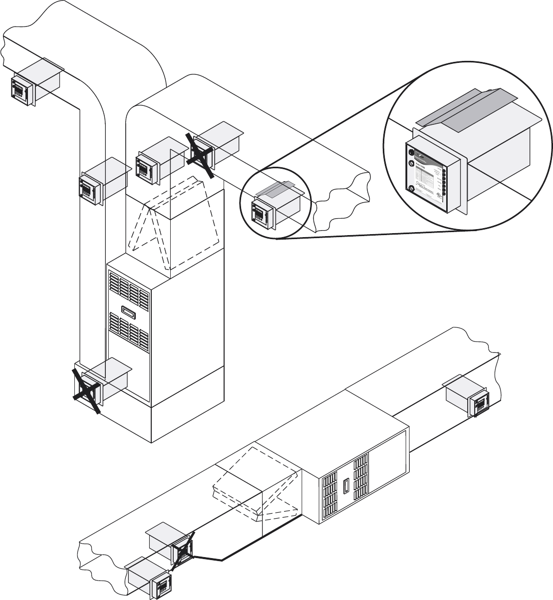
HVAC System. Notice that some of the locations are X’d out. These are poor locations for
the Steam Humidifer and may result in lower capacity output and/or excessive
condensation. Try to avoid mounting the unit within 2 feet of any 90 degree turns. Allow at
least 5 inches of clearance above the tank. The unit should not be installed within 5 feet of
an Electronic Air Cleaner, 4-5 inch thick Media filters, or a UV Lamp. Caution: UV lamps
may destroy certain plastics/rubber unless shielding is applied to those surfaces. DO NOT
install the Steam Humidifier on a Down-flow HVAC system. Avoid Fiberglass Duct-Board as
it cannot support the weight of the Steam unit when full of water. DO NOT install the Steam
Humidifier in an attic or crawl space exposed to freezing temperatures.
Figure 13.
Remember to insulate the water tank with the supplied insulation
wrap. Under extreme velocities it may be necessary to double
wrap the tank and/or the tank flange to prevent excessive heat
loss. Also remember to use gasket material on the duct opening
to prevent metal to metal heat loss and to prevent against
condensation and air leakage. On under-duct applications, it may
be necessary to insert an Air-Ramp in the duct to induce the
steam out of the tank. Contact Technical Support for assistance.
6
For Replacement Parts Call (800) 446-3110
09021A0118
U.S. PATENT NUMBER 5758 018
serial number
Ewc
385 Highway 33, Englishtown, NJ 07726
CONTROLS, INC.
UL
®
CUS
LISTED 141V
POWER
DRAIN
FILL
HEATER
BLOWER
Thermistor
Heater
Water
Suitable for Residential Use Only
Model S2020
Steam Humidifier
2.0 KW 240 Volt 8.3 Amps
®
HUMIDIFIER W/ SCOOP
Copyright © 2011 Field Controls All Rights Reserved.
Suitable locations to install your Steam Humidifer on an Up-flow or Horizontal
It is recommended that humidistat settings of 30-45% not be
exceeded. If condensation is noticed on windows during very
cold outside temperatures, the humidistat setting should be
lowered.
RELATIVE HUMIDITY CHART
The maximum recommended relative humidity for your
home depends upon many factors such as outdoor air
temperature, type and placement of insulation, vapor
barriers, effectiveness of weather stripping, type of windows
and doors (including frames and jambs) and whether or not
storm windows and doors are used. With all these variables it
is nearly impossible to recommend a proper humidity
setting. The best humidistat setting is one that you are most
comfortable with. Also, as the outdoor temperature
fluctuates, it may be necessary to adjust the humidity level of
your system a few times during the heating season.
Refer to the "Relative Humidity Chart" as a starting point for
your proper humidistat setting. Generally, in a tighter and
better insulated house, the humidistat may be set higher than
in a drafty, un-insulated house.
IMPORTANT: If the humidifier is installed in the return air
plenum the humidistat must be located at least five (5) feet
upstream from the humidifier. Fan should be operated in
continuos mode when the humidistat is mounted in the return
air plenum. Mounting the humidistat on an interior wall is
always preferable to mounting on the return duct. But
mounting the humidistat on an interior wall takes more time,
material and labor than a return duct location. Sometimes it
may be impossible to mount a humidistat on an interior wall
and the return duct location is the only solution.
Installation instructions for the 072000 model
Humidistat are packaged with the 072000.
Your humidifier may include Model 062000 Humidistat.
Installation instructions for the 062000 model are packaged
with the 062000.
There are many ways to wire and control a humidifier. Refer
to the wiring diagrams on pages 4 and 7.
10. SETTING THE HUMIDISTAT
RH
OD%RH
TEMP
MAN
AUTO
MODE
Outside
Dry Bulb
Temperature
Recommended Indoor
Relative Humidity
Setting
0 Deg. F
20 Deg. F
30 Deg. F
35 Deg. F
and up
10 Deg. F
15%
20%
25%
35%
40-45%
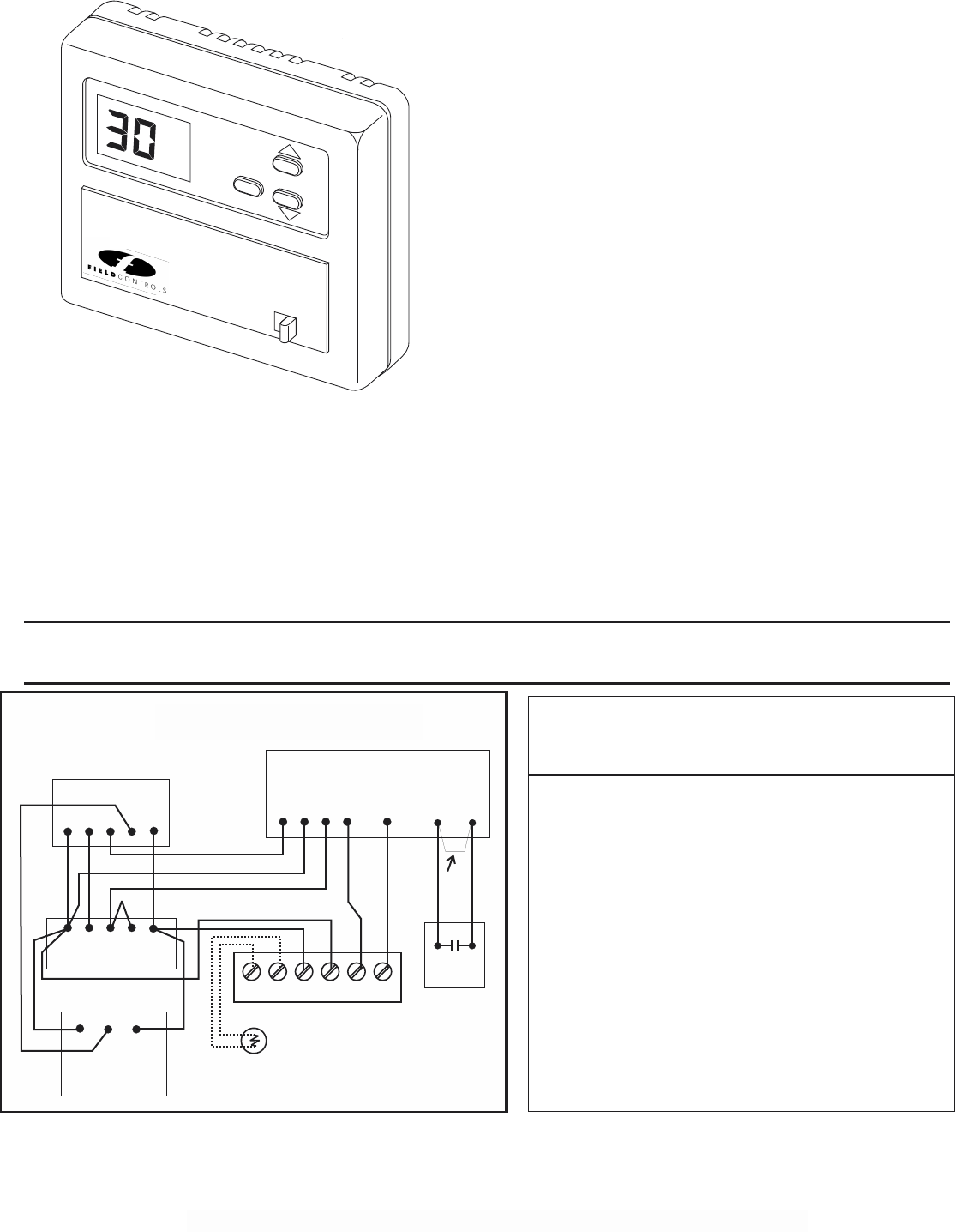
Variable Speed WIRING DIAGRAM
FIG. 15
Variable Speed Furnace
G1 R G2 H H
Typical Thermostat
G YWR
G YWR
Variable Speed Heat & Cool System and
A
A
S2000 & S2020 Humidifier
Low Voltage Terminal Block
REMOVE
FACTORY
JUMPER
C
C
OD OD C RHH
Outdoor
Temperature
Sensor
072000 Humidistat
YC
Hi-Efficiency
Condensing
Unit
R
7
Figure 14.
The diagram above should be followed if it is required to operate the fan system at high speed during the humidify operation. Such a
requirement may be necessary if condensation occurs inside the duct-work due to the lower velocities of a variable speed system
when only the fan is running. The “Y” circuit must be wired exactly as shown to achieve the correct operation. This wiring configuration may
result in the loss of the “enhanced” latent effect operations of your variable speed HVAC system. If you do not want this to happen, you
should consider installing a different type of whole house humidifier that does not require dominance over the HVAC fan and full CFM
capacities while operating. Variations on this diagram are available. Contact EWC Controls Technical Support Hotline.
Model APD or
Equivalent
Copyright © 2011 Field Controls All Rights Reserved.
Steam Humidifier with 072000 Humidistat
Variable Speed Heat & Cool System and
Steam Humidifier with 072000 Humidistat
Variations on this diagram are available. Contact Field Controls Technical Support Hotline.

INITIAL START-UP * SEQUENCE OF OPERATION * SERVICE “LED” INDICATORS
11. START -UP & OPERATING SEQUENCE
Once the Steam Humidifier has been installed and the
water, drain, humidistat and blower interlock
connections completed, the humidifier may be started.
A. Disconnect the water line. Turn on the water supply
and flush the line into a bucket. Reconnect the water line.
B. Set the humidistat to a setting higher than the room
RH level.
C. Plug the S2000 Humidifier line cord into a 120
VAC, 20 amp source. (240VAC,15amp for S2020).
D. The Green "POWER" LED should blink rapidly and
the drain valve will open momentarily upon initial start
up. The "FILL" LED will illuminate and water should
begin to fill the Water Pan. The Power LED will now
blink slowly.
E. When the water has reached the probe level the
"FILL" lamp and fill valve will be turned off, and the
"HEATER" LED and heater element will be turned
on. The “POWER” LED will blink slow and steady.
F. Once the water reaches 170 deg. F. the "BLOWER"
LED will illuminate and the system blower should start
up.
G. If the above steps have been successfully completed,
the humidifier is operating properly.
A. POWER: In normal standby mode, when the
humidistat is not calling for humidity and the power
cord is plugged in, the "POWER" LED should be
blinking slowly. If the green "POWER" LED is not
flashing when there is power to the unit, the CPU and/or
circuit board may have failed.
B. FILL: When the humidistat closes, on a call for
humidity, the "FILL" LED is illuminated, the Solenoid
Valve is open and the water reservoir is filling.
C. HEATER: When the water reaches it's proper level
the valve closes, the "FILL" LED goes out, the
"HEATER" LED is illuminated, and the Heater begins
to heat the water.
NOTE: If the humidifier is unplugged while in
steaming operation and then plugged back in, A
rapid flashing of the “POWER” LED will occur
and all other functions will stop! The unit wants to
perform a water probe test, but cannot perform
this test until the water cools down. Simply wait
until the unit cools down and it will resume
normal operations. To accelerate a cool down,
simply turn the HVAC system fan on via the
thermostat.
D. BLOWER: When the water in the reservoir reaches
approximately 170 deg. F. the "BLOWER" LED will
be illuminated and the interlock wiring should turn the
system blower on. Depending upon the water and
ambient temperatures, it may take anywhere from four
to twelve minutes for the water to heat to 170 deg. F. If
the humidistat remains closed the "HEATER" and
"BLOWER" LED's will both be illuminated at the same
time and the "POWER" LED will be blinking slowly.
E. The "FILL" LED will illuminate and the water
reservoir will refill at irregular intervals, depending on
the boil off rate. The "HEATER" LED should remain
illuminated unless the humidistat opens or the
humidifier enters a drain cycle or failure mode.
F. DRAIN: This LED will be illuminated when the
microprocessor cycles the humidifier into a
Maintenance Mode. After a fan forced cool down
period, the water is allowed to drain at 140 degrees F.
The drain valve will then close and the fill valve will
open to refill the reservoir and resume normal operation.
This mode will last about one hour and the
microprocessor will automatically restart the unit
afterwards, if there is a call for humidity. This drain
cycle will occur once every 8-12hours, to reduce the
mineral concentration in the tank and let the heater cool-
down. That will shed most deposits that have built up
on the heater. NOTE: The "POWER" LED will
blink rapidly during Maintenance mode.
NOTE: A unique feature of the “S” series humidifiers
is called “Fill on Request”. The unit will not refill with
water after a maintenance cycle, unless there is a
demand for humidity from the humidistat. This
ensures that the unit will not sit idle with standing
water, which can stagnate over time.
G. FAILURE LED'S: When service is required,
these LED's will illuminate. If the humidifier enters a
failure mode, it must be manually reset by
disconnecting the power and then reconnecting it. If
the “Air” failure LED occurs, simply turn the
Humidistat off or down then back up again to reset.
WATER: This will occur when the reservoir is not
filling up with water, not filling fast enough or the
microprocessor cannot recognize that the water is
touching the probe. Reverse Osmosis water or purified
(distilled/deionized) water sources should be avoided,
unless the final feed water measures at least 25 ppm
conductivity.
HEATER: This will occur if the humidifier is not
boiling off water during the "HEATER" cycle. Water
in the reservoir is not reaching 170 deg. F. temperature,
or the unit has not detected a request for water in a 50
minute steaming time period. Both red LED’s will
illuminate in this condition.
AIR: This will occur if the humidifier detects a loss of
air flow for more than 4 minutes. A field supplied air
proving device must be installed, wired and tested.
THERMISTOR: This will occur if a short or open is
detected in the temperature probe.
8
12. SERVICE “LED” INDICATORS
14. SERVICE INDICATORS
Seven LED lamps provided on the front panel indicate the
functional status of the humidifier as shown in Figure 7 below.
9
A.
L.
M.
N.
O.
B.
C.
D.
E.
F.
G.
H.
I.
J.
K.
Unplug the power cord from the 120 volt source for
S2000 (240 volt for S2020) and allow the water to cool for
at least 30 minutes prior to removal.
Turn off the water supply at the saddle tapping valve.
Remove the cable assembly wire plug from the top of the
plastic control housing.
Drain the water with the manual drain valve. NOTE: The
drain valve will be hot if the humidifier has not been
allowed to cool.
Disconnect the water and drain lines. NOTE: Some water
may drain out of the water line. Have a small container
ready to catch the water.
NOTE: Although the water has been drained, some water
may still remain in the humidifier reservoir along with
sediment. Be careful not to tip the unit over when
removing it from the duct.
Remove the eight (8) screws from the front mounting
plate.
Slide the humidifier out of the duct.
Remove the two (2) screws holding the tank baffle to the
pan flange and remove the baffle from the unit. Scrape all
mineral deposits from the baffle and wash baffle off as
described in step J. Remove the Anode from the baffle
plate and purchase a new one. Operating the unit without
the Anode will degrade the performance and increase
maintenance.
Use a putty knife to scrape the minerals from the sides and
bottom of the water reservoir. DO NOT scrape on the
small temperature probe, or the heater element. Use a soft
emory cloth or stiff nylon brush. If necessary, fill the tank
with vinegar and let it sit for several hours or even over-
night allowing the scale to soften and making it easier to
remove.
Carefully scrape the Water Level Probe to remove
mineral deposits. Use soft emory cloth if necessary.
Clean the Water Probe Insulator, inside the pan, with a
cloth and 50-50 mixture of water and vinegar, rinse with
fresh water. Inspect for any mineral deposits on the plastic
insulator. Repeat cleaning if necessary and thoroughly
dry. Use a small nylon brush to clean deposits off the
heater element and thermistor probe. Be careful not to
damage any of the components.
Rinse out the reservoir. Be careful to keep water off of the
wiring compartment and the front cover of the humidifier.
Allow the unit to dry thoroughly before using!
Reinstall the tank baffle and tighten the two (2) screws.
Re-install the unit in the duct and connect the water line and
the drain lines. Store the unit in this condition for the
summer, or continue to the next step.
START -UP
Turn on the water supply. Inspect the water connections and
drain fittings for leaks.
Plug-in the S2000 power cord to the 120 VAC (240 VAC for
S2020) grounded outlet. DO NOT use an extension cord.
1. The green POWER light should blink rapidly until it
detects a demand to humidify, then it will blink slowly.
2. If the humidistat is calling for humidity the water
valve will energize and the water pan will fill with water.
3. The Heater element will energize to heat the water, and
the Fan will start up to distribute the moisture
Maintenance and inspection of the unit requires removal
of the humidifier from the duct. This can be done
following these steps.
13. MAINTENANCE/SPRING SHUTDOWN
Proper maintenance and removal of mineral deposits is still
required on your steam humidifier in order to optimize
performance. Annual cleaning is a must and more frequent
cleaning may be necessary depending on the mineral content
of the water in your area.
A post winter cleaning and shutdown, will prevent hard
deposits from accumulating inside the bin, while the
humidifier is idle over the summer. Do not allow the unit to sit
idle for long periods without a proper cleaning and shutdown.
Failure to do so will affect the performance of your steam
humidifier.
FIG. 16
LED LIGHT EXPLANATION
IMPORTANT NOTE
POWER - GREEN - BLINKING SLOWLY-IF POWER TO UNIT
THERMISTOR FAILURE - RED - ON STEADY
HEATER FAILURE - RED - BOTH LED'S ON STEADY
AIR FLOW FAILURE - RED - BOTH LED’S ON FLASHING
WATER FAILURE - RED - ON STEADY
BLOWER - AMBER - ON STEADY WHILE PAN ABOVE 170 DEG F.
HEATER - AMBER - ON STEADY WHILE HEATING (BOILING)
FILL - AMBER - ON STEADY WHILE FILLING PAN
DRAIN - AMBER - ON STEADY WHILE DRAINING PAN
ON THE INITIAL FILL AFTER INSTALLATION OR ANY TIME THE WATER PAN IS DRAINED THE PAN
MUST FILL WITH ABOUT THREE (3) TIMES THE AMOUNT OF WATER AS REQUIRED IN THE NORMAL
CYCLE OF FILLING. THE 'FILL TIMER' MAY TIME OUT BEFORE THE WATER LEVEL REACHES THE
WATER LEVEL PROBE CAUSING THE 'SERVICE CYCLE' TO BE STARTED. IF THE WATER FAILURE
ILLUMINATES, UNPLUG THE UNIT FROM ITS POWER SOURCE, WAIT ABOUT 15 SECONDS AND
RECONNECT THE POWER SOURCE. THE SERVICE LIGHT WILL GO OUT AND THE UNIT WILL
CONTINUE FILLING TO THE CORRECT LEVEL.
For Replacement Parts Call (800) 446-3110
09021A0118 REV. J
BUILT UNDER U.S. PATENT
NUMBER 5758018
serial number
385 Highway 33, Englishtown, NJ 07726
LISTED 141V
POWER
DRAIN
FILL
HEATER
BLOWER
Thermistor
Heater / Air
Water
Suitable for Residential Use Only
Model S2020
Steam Humidifier
2.0 KW 240 Volt 8.3 Amps
®

10
A.
G.
B.
C.
D.
E.
F.
The green "Power" light does not blink off and on.
1. The S2000 is not connected to an active 120
VAC 15 Amp power source. (S2020, 240 VAC,
10 AMP).
2. Call the Technical Support Hotline.
The "HEATER" LED does not illuminate.
1. The humidistat is not closed, calling for humidity or the
humidistat is wired incorrectly.
2. The unit is in the maintenance cycle.
The HVAC Blower will not operate, but the "Blower"
LED is on.
1. The blower "Field" wiring and/or interlock circuitry is
incorrect.
2. The HVAC electric power is disconnected.
3.The humidifier internal "Blower" relay is defective. Call
the Technical Support Hotline.
4. The HVAC Blower motor has failed.
The HVAC Blower will not operate and the "Blower"
LED is not on.
1. The water pan temperature has not reached a high enough
temperature to activate the "Blower" relay, about 170
degrees Fahrenheit. This takes several minutes after the
"HEATER" LED is illuminated. Depending on the water
temperature and the surrounding condition, this may take
up to 12 minutes. If the problem continues, the heater
element may be defective or the thermistor temperature
probe may be defective. Contact the Technical Support
Hotline.
Red Service Light (error #1) is on constantly.
THERMISTOR FAILURE ...This is an indication that the
temperature probe is open or shorted to ground. May also
indicate the probe has detected a pan temperature below 32
degrees F. Or in excess of 230 degrees F., resulting in a total
shutdown. Try to reset the unit by unplugging the cord and
reconnecting, or call Technical Support.
Red Service Light (error #2) is on constantly.
WATER FAILURE ...This is an indication that the water fill
time has been exceeded. The water level did not reach the
probe tip in the given amount of time. It may also indicate
an unsuccessful drain cycle.
1. The water line is shut off at the saddle valve.
2. The water line is crimped or pinched.
3.The water valve inlet screen is plugged. Remove the
water line from the unit and check the screen found inside
the inlet side of the valve.
4.Unit is connected to a water source which is distilled,
over-filtered, de-mineralized, or from a reverse osmosis
system. Minimum 25 ppm water conductivity is
required. *The unit supply water must contain dissolved
solids in the water, or the processor will not be able to
detect the water level.
5.The water valve may be defective and must be replaced
See replacement parts.
6. The drain valve is unplugged or defective.
7. Debris is clogging the drain valve or drain line.
8. Reset the unit by unplugging the power cord and re-
connecting.
Both Red Service Lights (error #3) are on constantly.
HEATER FAILURE...This is an indication that the water
temperature is not increasing or reaching the boiling
point.
1. Faulty heater element or faulty wire connection.
2. This can happen if the unit is operated without water
in the pan as a result of a water level probe malfunction,
due to lack of maintenance. The pan boils dry and over-
heats the water pan. If this condition occurs, call the
Technical Support Hotline.
3. The unit has operated for 45-50 minutes without a
request for water, due to a leaking water fill valve, which
is filling the tank continuously.
Both Red Service Lights (error #4) are flashing.
AIRFLOW FAILURE … This is an indication that the
system blower is not running or the blower/fan proving
device has failed, is malfunctioning, or is not wired
correctly. Check the blower motor and the interlock
wiring. Refer to page 4, Figure 11.
If the humidifier seems to operate in a random manner
that doesn't seem to fit any of the pre-described
conditions, check the following:
1. Check to make sure that the wires used to connect the
humidifier to the humidistat are separate wires and not
part of a multi-wire bundle used to hook up the furnace
thermostat or any other device. The associated close
wires may create an induced voltage in the humidistat
wiring.
2. Make sure that the water level probe and plastic
insulator are clean and free of mineral build-up. It may
become electrically conductive to ground, sensing a false
indication that the water level is correct.
3. If the electric solenoid valve makes a loud noise when it
closes, install an optional water hammer arrester to absorb
the spike. Frequent or erratic water fill cycles can be due
to air turbulence, when mounted in the supply air plenum.
4. The water probe uses the natural conductivity of the
water, to determine the proper water level in the reservoir.
Water that has been de-mineralized or over filtered may
not allow the unit to function properly. Minimum 25 ppm
of total dissolved solids must be present in the water.
Add approximately 1 tablespoon of salt to the tank, to
temporarily fix this problem.
5. These steam humidifiers must be connected to
dedicated outlets of the proper current and voltage ratings.
The use of extension cords is not recommended.
DO NOT cut off the grounded plug and/or
hard wire this humidifier to line voltage.
This will void the warranty.
I.
SERVICE INDICATORS
H.
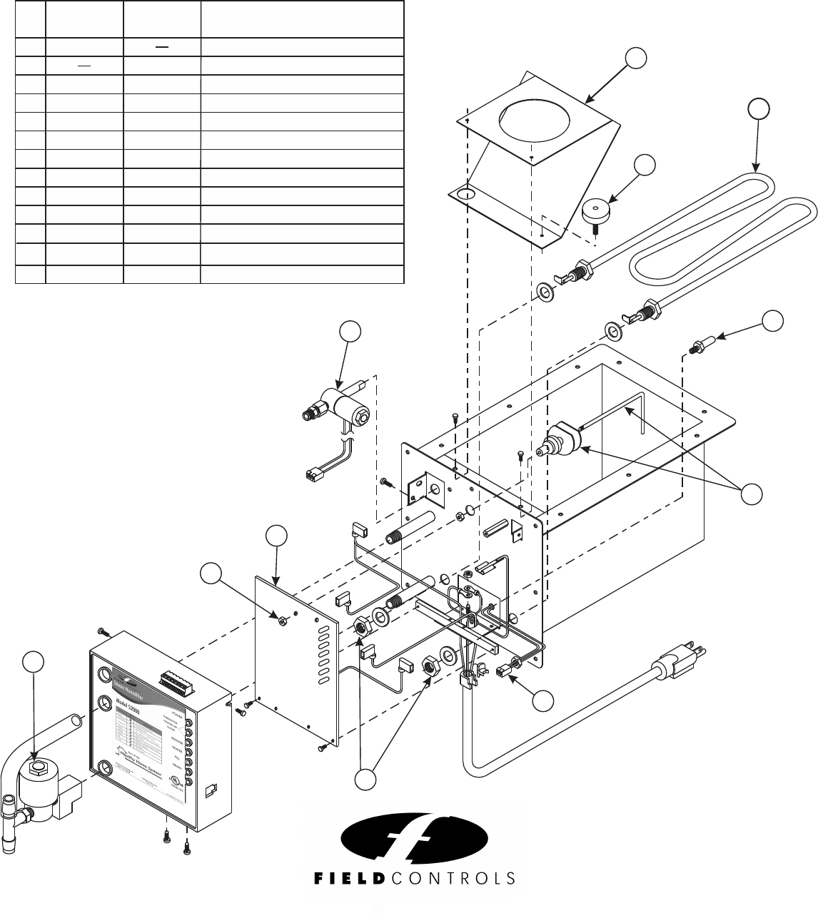
SERVICE AND REPLACEMENT PARTS
11
ITEM
1 120 VOLT HEATER ASSEMBLY
240 VOLT HEATER ASSEMBLY
24 VOLT SOLENOID VALVE ASSEMBLY
WATER LEVEL PROBE ASSEMBLY
THERMISTOR PROBE ASSEMBLY
CIRCUIT BOARD ASSEMBLY
DRAIN VALVE ASSEMBLY
TANK BAFFLE
WATER HAMMER ARRESTER (not shown)
ANODE
INSULATION KIT (not shown)
2002
2003
2007
2008
WH 100 WH 100
Z 100 Z 100
2004
2006
2120
2001
2240
2002
2008
2005
2006
2003
2007
2001
1
2
3
4
5
6
7
8
9
10
DESCRIPTION OF PART
S2000 S2020
PART NO. PART NO.
11 2009
2009 UNDER DUCT STEAM COVER (not shown)
For Replacement Parts Call (800) 446-3110
09021A0118
U.S. PATENT NUMBER 5758 018
serial number
Ewc
385 Highway 33, Englishtown, NJ 07726
CONTROLS, INC.
UL
®
CUS
LISTED 141V
POWER
DRAIN
FILL
HEATER
BLOWER
Thermistor
Heater
Water
Suitable for Residential Use Only
Model S2020
Steam Humidifier
2.0 KW 240 Volt 8.3 Amps
10
7
1
3
4
2
4
5
6
1
3
Figure 17.
12 APD APD AIRFLOW PROVING DEVICE (not shown)
®
Copyright © 2011 Field Controls All Rights Reserved.
2630 Airport Road
Kinston, NC 28504
PH: 252.522.3031 FAX: 252.522.0214
fieldcontrols.com
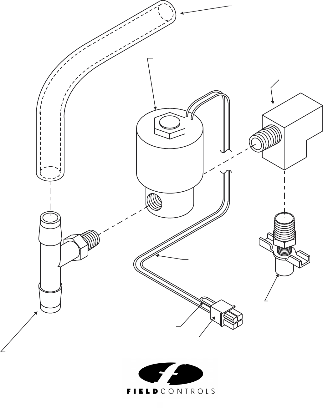
Figure 18
12
DRAIN COCK VALVE
"T" ADAPTER, 1/4" NPT
OVERFLOW TUBE,
.50 ID x 6" LG.
BARBED TEE,
1/4-18 NPT TO ½"
JUMPER WIRE,
20GA. X 1.50" LONG MOLEX PLUG
BLACK WIRES
18GA. X 18" LONG
SOLENOID VALVE, 24/60 VAC
2630 Airport Road
Kinston, NC 28504
PH: 252.522.3031 FAX: 252.522.0214
fieldcontrols.com
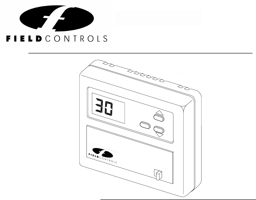
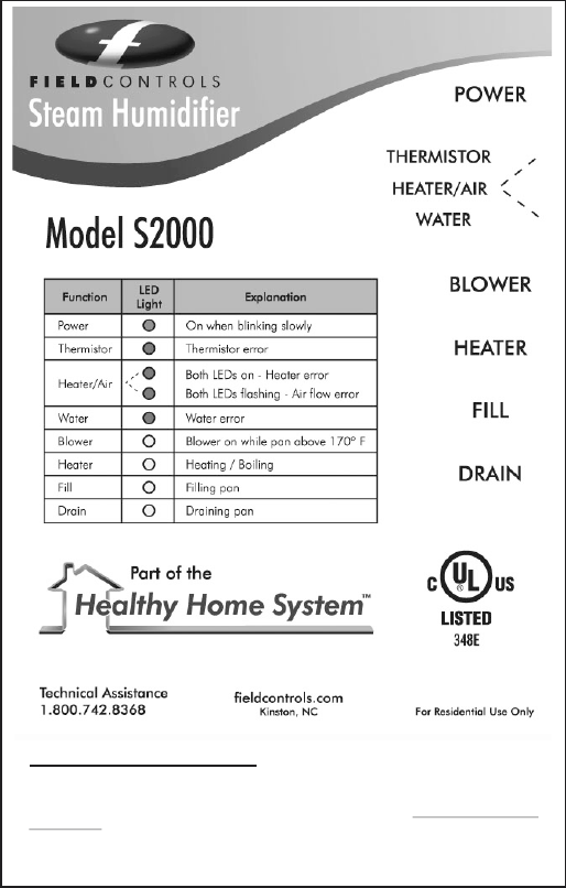
Smart Digital Humidistat
Installation and Owner's Manual
The 072000 is a digital humidifier control
that can automatically adjust the indoor
humidity set point as the outside air
temperature changes. This intelligent
control will maintain accurate humidity
levels and a more comfortable indoor
environment.
The actual indoor relative humidity is
always displayed on the LCD screen. When
the or down keys are pressed, the
humidity set point is displayed and can be
adjusted using the up and down arrow
keys.
An outdoor temperature sensor is included,
and must be connected in order to fully
utilize the features of the 072000. The
outdoor temperature sensor allows the
humidistat to automatically adjust the
humidity set point, to avoid condensation on
windows. It is also a convenient way to read
the outdoor air temperature at any time.
up
The outdoor sensor is not required to
use the Humidistat in the basic or
manual mode.
The 072000 operates on 24vac, and has
a set of isolated dry contacts for
activating the humidifier. Terminals are
also provided for the Outdoor air
Temperature Sensor. (Part# OAS)
The 072000 can be installed on the
return air duct or, it can be installed on an
interior wall within the conditioned
interior wall installation. NOTE: If the
return air duct is chosen as the location,
the HVAC fan should be set to run
continuously, in order to obtain an
accurate sampling of the actual living
space relative humidity condition.
General Description
TECHNICAL BULLETIN
RH
OD%RH
TEMP
MAN
AUTO
MODE
Package includes:
1 #072000 Smart Humidistat
1 Foam Gasket
1 Mounting Template
1 Technical Bulletin #TB213
2 Mounting screws
2 Wall anchors
1 #OAS Outside Air Sensor
Your new
Steam
Humidifier may
include this
control. The
instructions are
included!
Please refer to
this Bulletin.
®
TB 213 P/N 090375A0213 REV. F 10/2011 Copyright © 2011, Field Controls Inc., All Rights Reserved
space. Field Controls recommends an
Field Controls Model 072000

Z100 ASSEMBLY
INSTALLATION INSTRUCTIONS & OWNER'S MANUAL
Z100 REPLACEMENT INSTRUCTIONS
ELECTRONIC STEAM POWER HUMIDIFIERS
MODEL # S2000 AND S2020
APPLICATION NOTE
AN 131
Copyright © 2011 Field Controls All Rights Reserved.
SUPPLEMENT TO THE
The Field Controls Steam Humidifier now comes equipped with a factory installed Z100, which acts
as a sacrificial metal. Put simply, minerals in the water will attack and cling to the Z100. The
minerals will not attack the other components inside the humidifier as long as the Z100 is present
and active.
This results in a dramatic decrease in mineral and scale build up on the critical components inside
the tank. In particular, it means less scale build up on the heating element which is subject to
damage from excessive scaling and over heating. This also means that efficiency stays high and
preventive maintenance is faster and easier.
The Z100 is positioned on the baffle plate inside the tank and is easily removed and replaced.
Remember that the Z100ʼs job is to become the target of mineral attack, so it will be heavily
covered with scale and should be replaced annually for best results.
To remove the Z100 you must have already unplugged and shutdown your steam humidifier and
allowed it to cool. The water tank has been drained, the water supply, drain lines and electrical
wiring have been disconnected and the unit has been removed from the duct.
Refer to the blow up view on Page 11. Using a phillips screwdriver, remove the two screws that
hold the baffle plate to the tank. Lift the baffle slightly back to clear the water probe and then straight
up and out of the tank. You can then see the round Z100, or rather what is left of it after a single
season. Notice the heavy scale build up on the Z100 that would have been on your element, if the
Z100 was not there. Use a rag or pliers to grasp the edges of the Z100 and simply unscrew it from
the baffle plate. Rinse off or wipe away any residual scale from the baffle plate and install a new
Z100. Leave a slight gap between the bottom of the Z100 and the baffle plate. Now re-insert the
baffle plate into the tank and secure with the two screws that were removed previously. Itʼs that
simple.
The Z100 can also benefit the older model steam humidifiers. Simply lay the Z100 down into the
baffle plate in the same location as the factory installed model. DO NOT lay the Z100 down into the
main tank. It may come in contact with the heating element and damage it. The dimensions of the
baffle plate prevent the Z100 from falling down into the tank.
Field Controls Inc. 2630 Airport Road Kinston, NC 28504 PH: 252.522.3031 FAX: 252.522.0214
APPLICATION NOTE
PART # 2009
AN 151
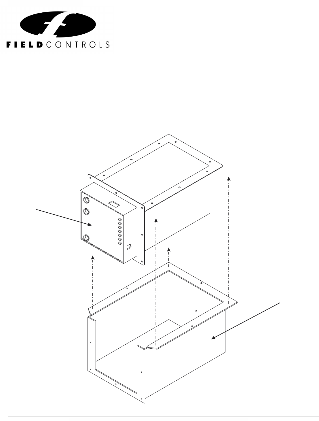
SC100 - PART # 2009
DECORATIVE COVER
S2000/S2020
STEAM HUMIDIFIER
SC100 Installation Instructions
P/N 090376A0151 REV. A Copyright 2011 © Field Controls Inc., All Rights Reserved
SUPPLEMENT TO THE ELECTRONIC STEAM
POWER HUMIDIFIERS
MODEL # S2000 AND S2020
The Field Controls Steam Humidifier can be equipped with a field installed Decorative and Protective
Cover for Under the Duct Installations only. The SC100 provides a protective shell around the exposed
insulated tank and provides a visually pleasing finish to the installation.
Field Controls Inc. 2630 Airport Road Kinston, NC 28504 PH: 252.522.3031 FAX: 252.522.0214
16
Model Number:____________________Serial Number:____________________Date Code:_____________________
Date Purchased:_________________________________________________________________________________
Date Installed: __________________________________________________________________________________
Date Inspected:__________________________________________________________________________________
Maintenance Schedule:
Annually Bi-Annually Quarterly Monthly
Date of Service:__________Service Performed:________________________________________________________
Date of Service:__________Service Performed:________________________________________________________
Date of Service:__________Service Performed:________________________________________________________
Date of Service:__________Service Performed:________________________________________________________
Date of Service:__________Service Performed:________________________________________________________
Date of Service:__________Service Performed:________________________________________________________
Date of Service:__________Service Performed:________________________________________________________
Date of Service:__________Service Performed:________________________________________________________
Date of Service:__________Service Performed:________________________________________________________
Date of Service:__________Service Performed:________________________________________________________
Date of Service:__________Service Performed:________________________________________________________
Date of Service:__________Service Performed:________________________________________________________
Date of Service:__________Service Performed:________________________________________________________
Date of Service:__________Service Performed:________________________________________________________
Date of Service:__________Service Performed:________________________________________________________
Date of Service:__________Service Performed:________________________________________________________
COMMENTS:___________________________________________________________________________________
______________________________________________________________________________________________
______________________________________________________________________________________________
______________________________________________________________________________________________
______________________________________________________________________________________________
______________________________________________________________________________________________
______________________________________________________________________________________________
______________________________________________________________________________________________
______________________________________________________________________________________________
DOCUMENT YOUR PRODUCT, INSTALLATION & MAINTENANCE DATA HERE FOR FUTURE REFERENCE!
Copyright © 2011 Field Controls All Rights Reserved.
Field Controls Inc. 2630 Airport Road Kinston, NC 28504 PH: 252.522.3031 FAX: 252.522.0214
