Fimi Srl 802120 Web PAD User Manual CMPD12 indd
Fimi Srl Web PAD CMPD12 indd
UserManual.wiki
>
Fimi Srl
>
802120 User Manual
>
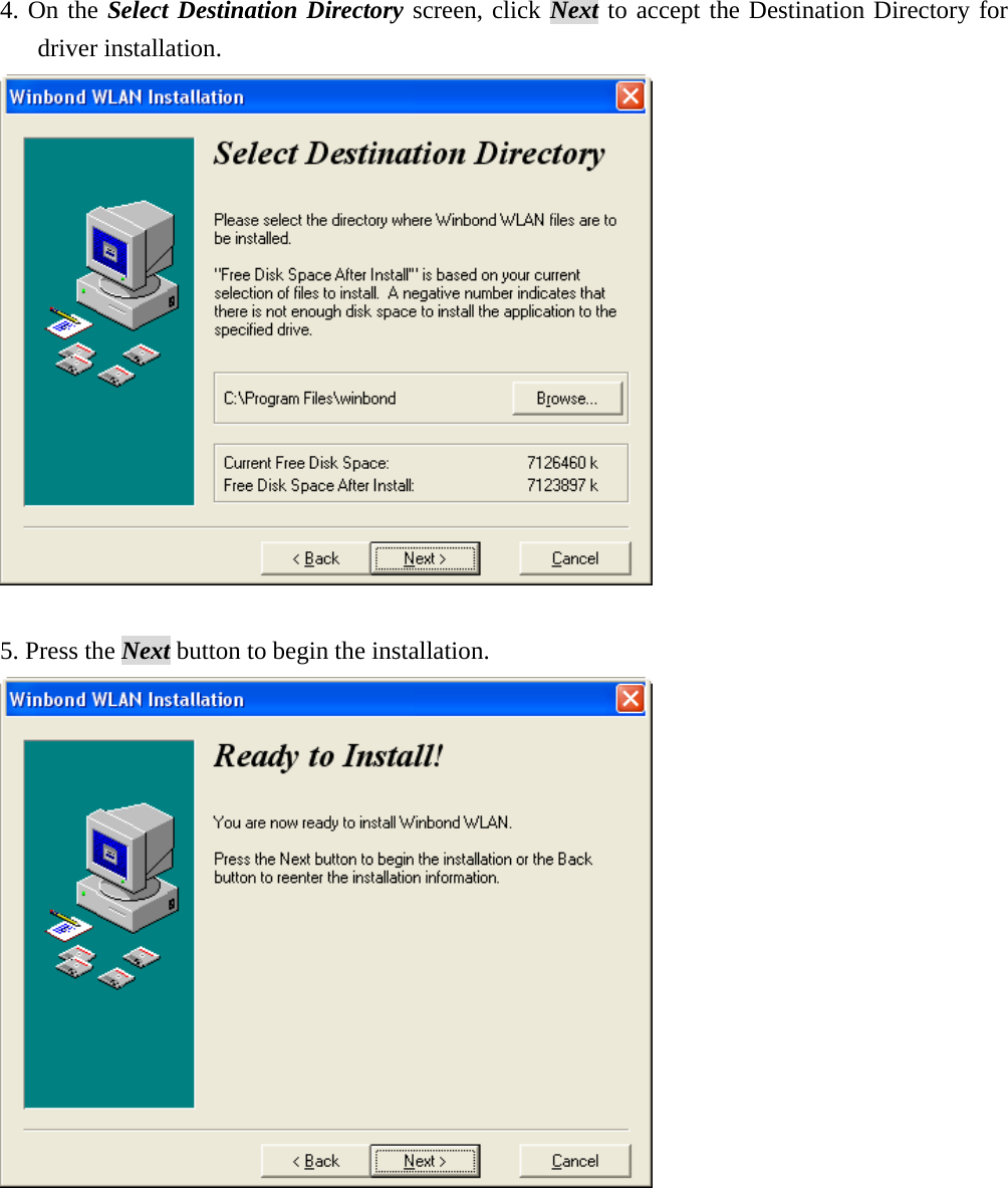
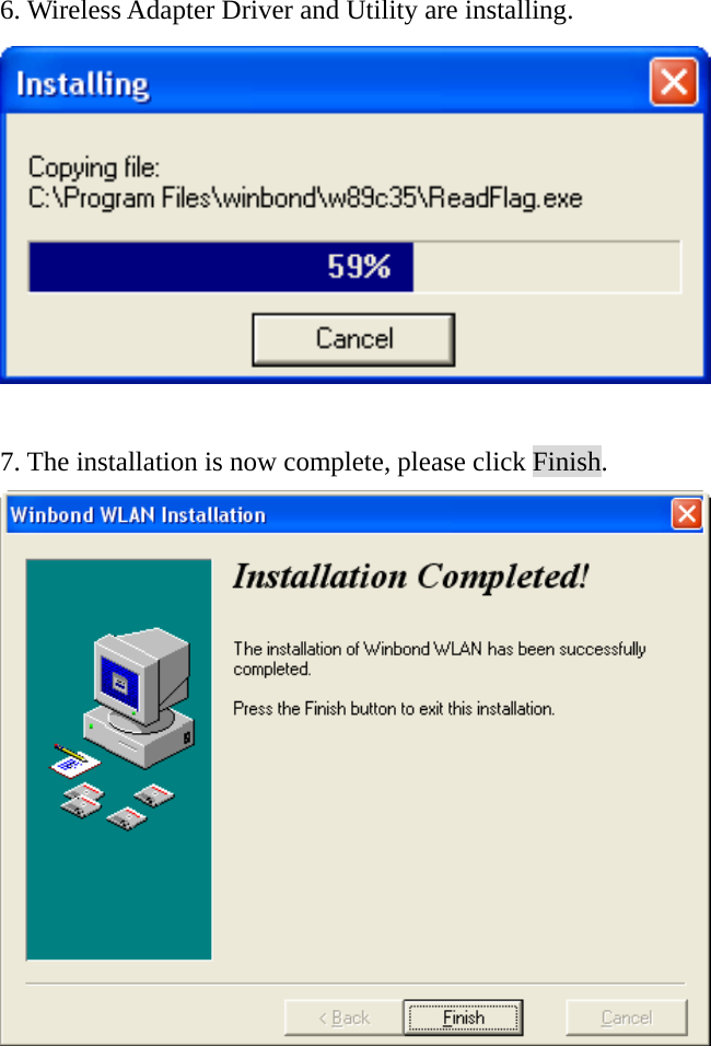
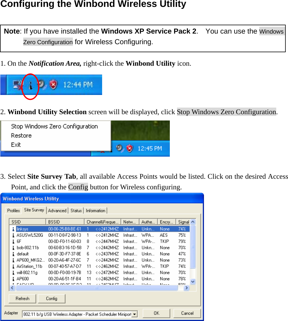
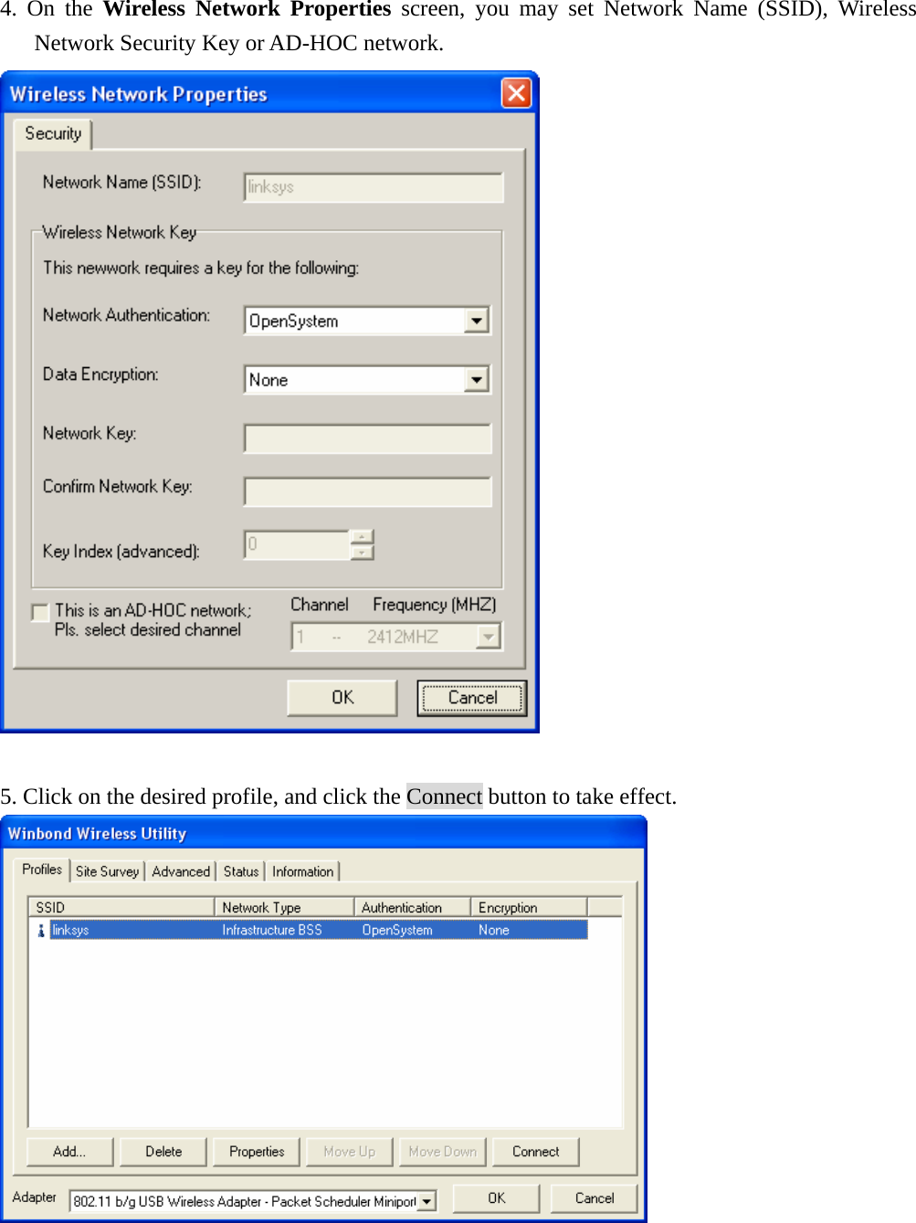
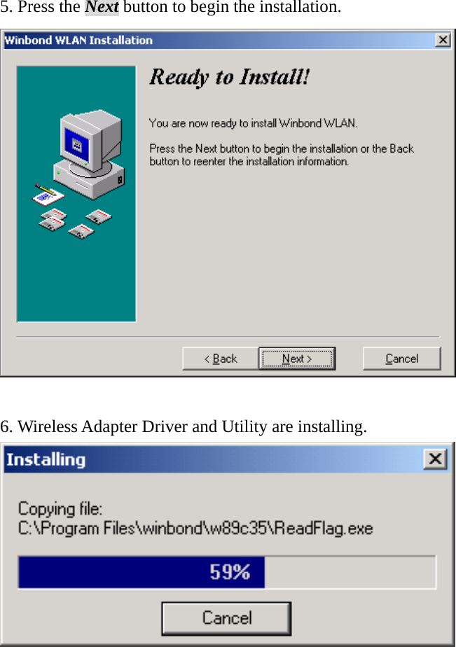
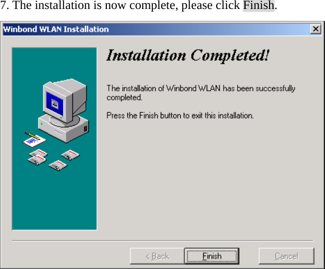
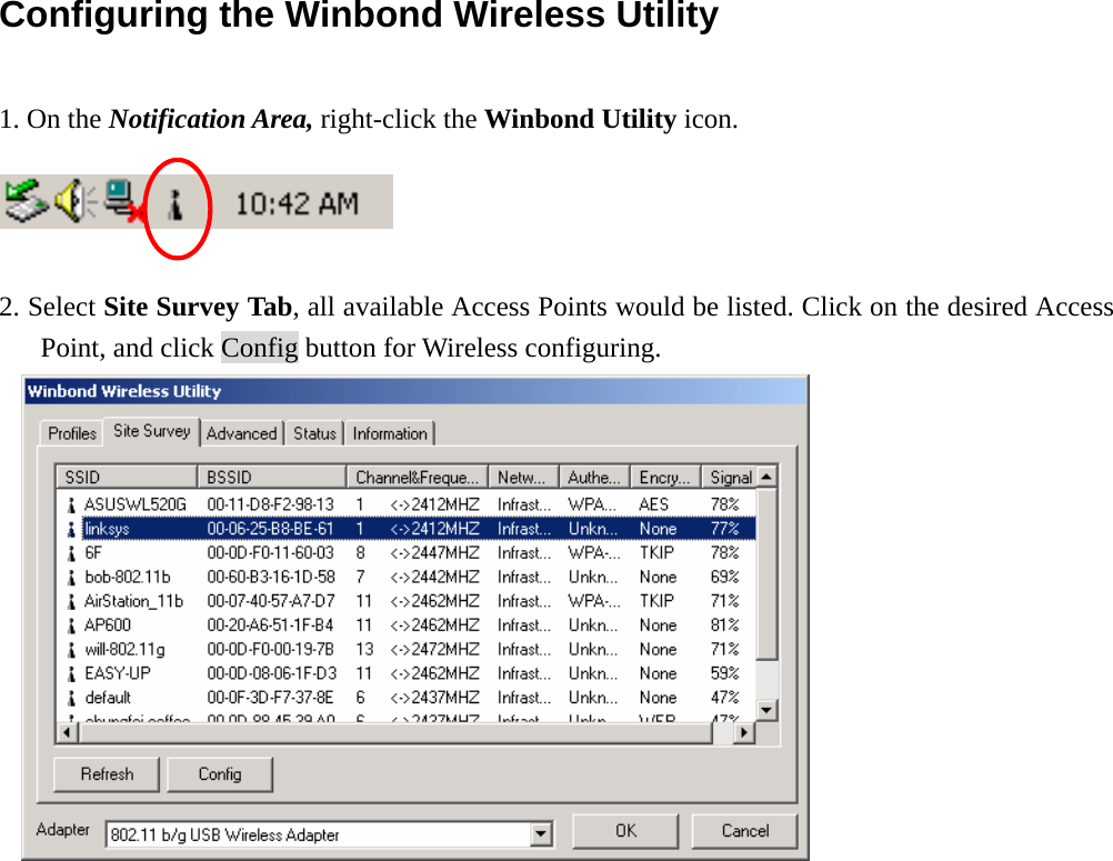
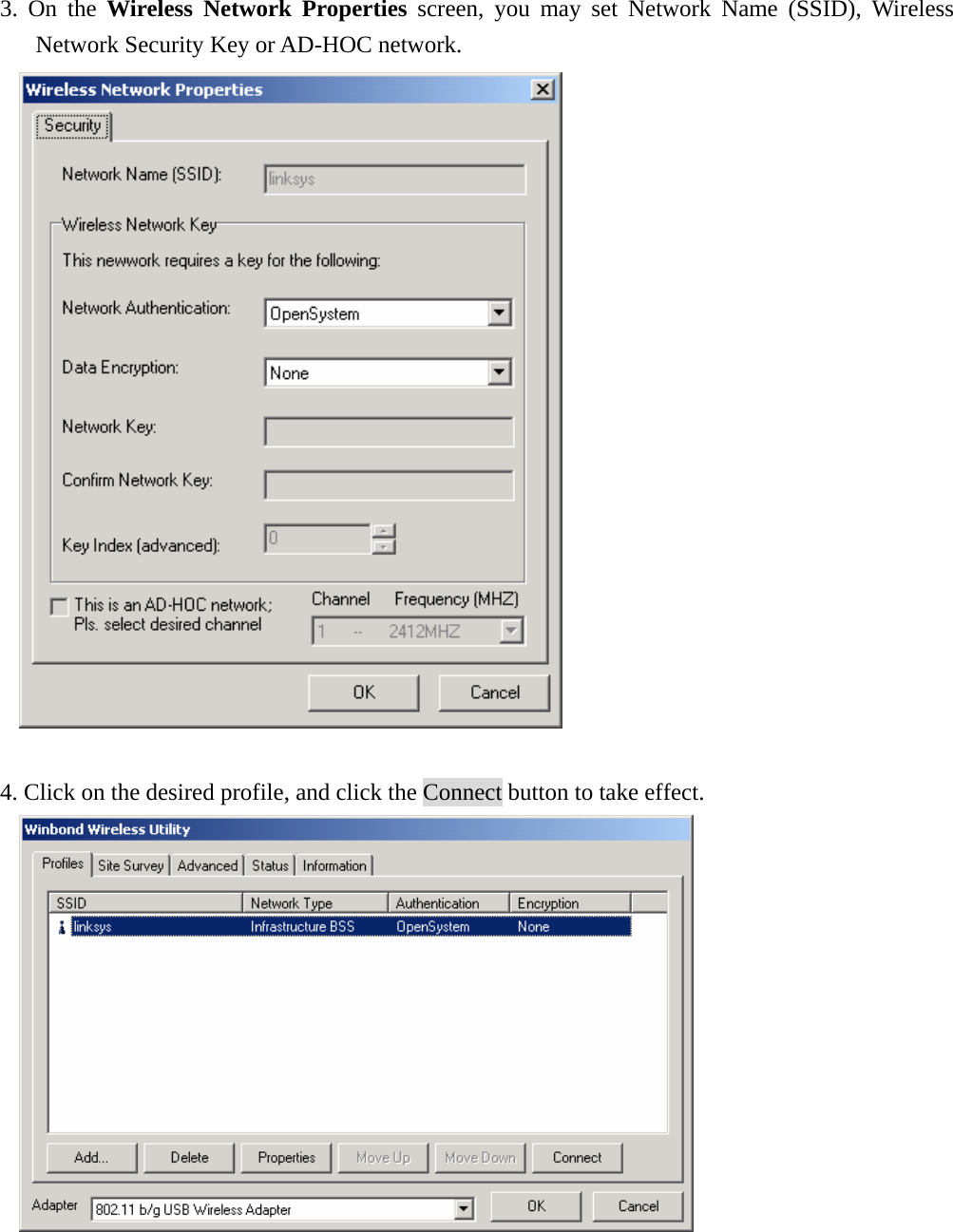
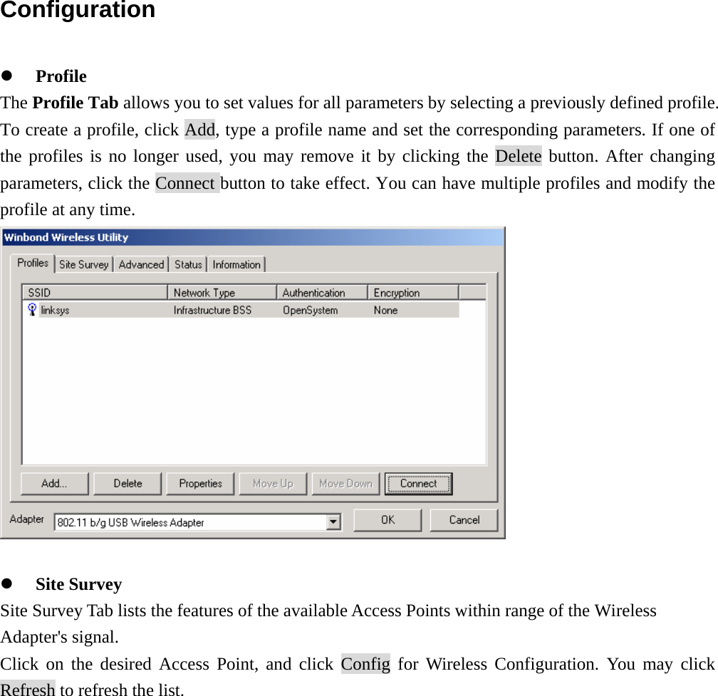
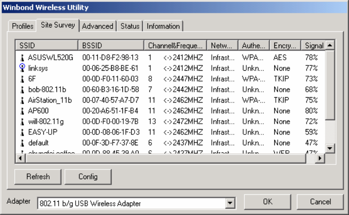
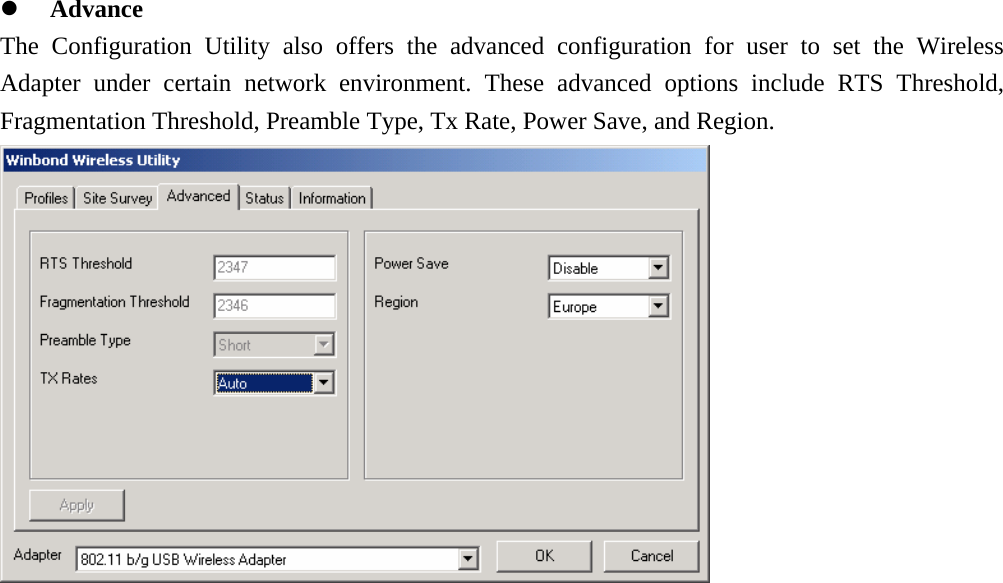
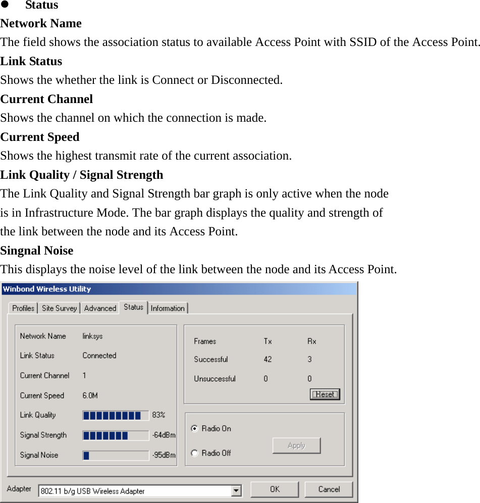
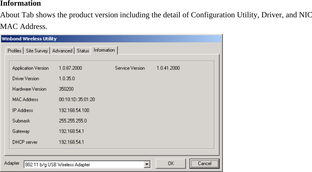
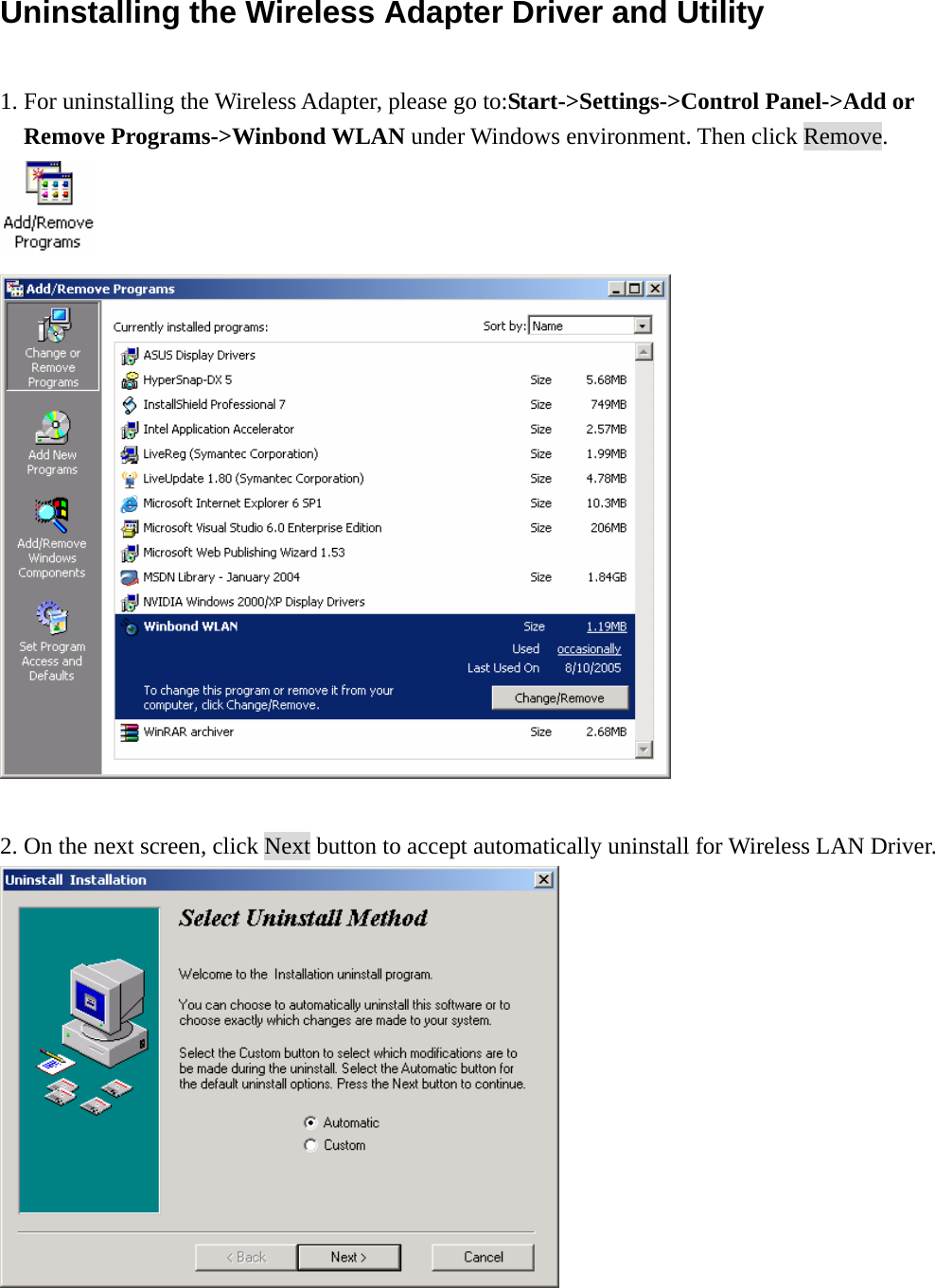
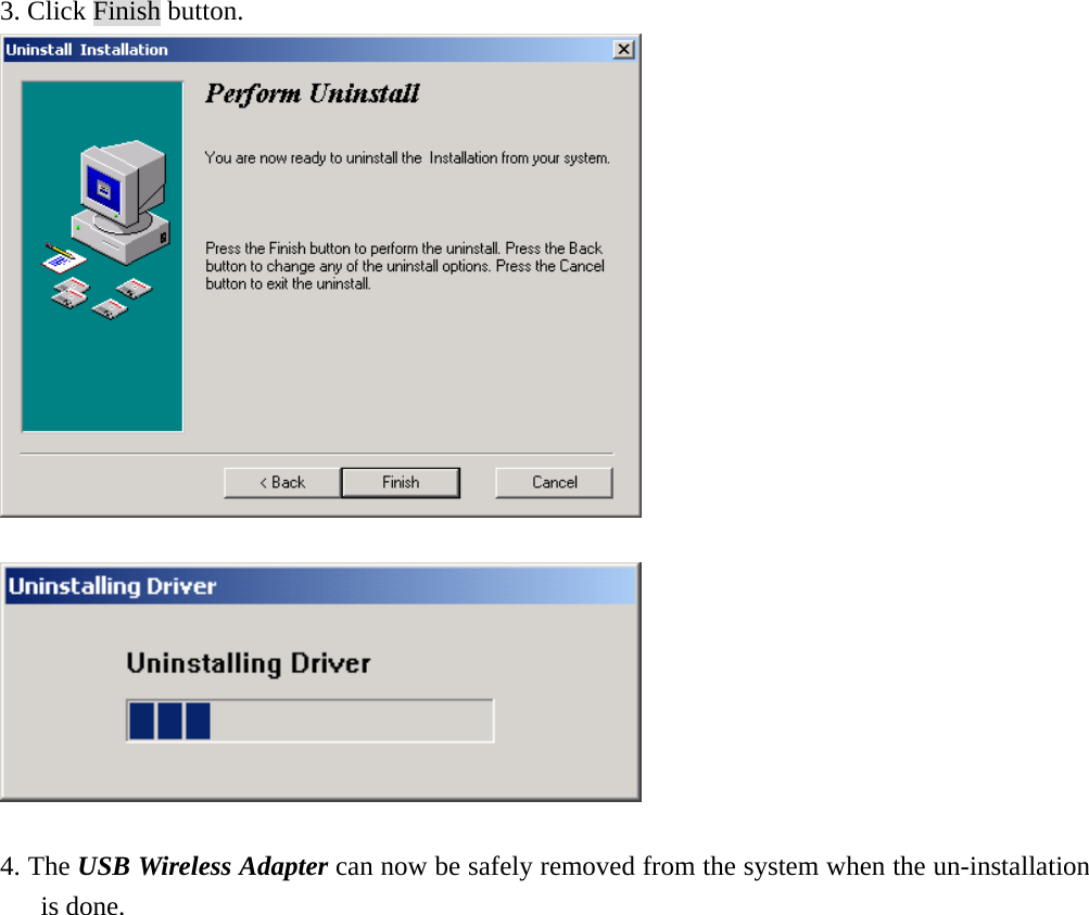
User Manual
Contents
1.
User Manual
2.
Users Manual
User Manual
Navigation menu
Upload a User Manual
Namespaces
Wiki Guide
HTML
PDF
Info
Views
User Manual
Discussion / Help
Navigation