Fimi Srl 802180 RFID Computing Platform User Manual MCA 104 series
Fimi Srl RFID Computing Platform MCA 104 series
UserManual.wiki
>
Fimi Srl
>
802180 User Manual
User Manual
Navigation menu
Upload a User Manual
Namespaces
Wiki Guide
HTML
PDF
Info
Views
User Manual
Discussion / Help
Navigation
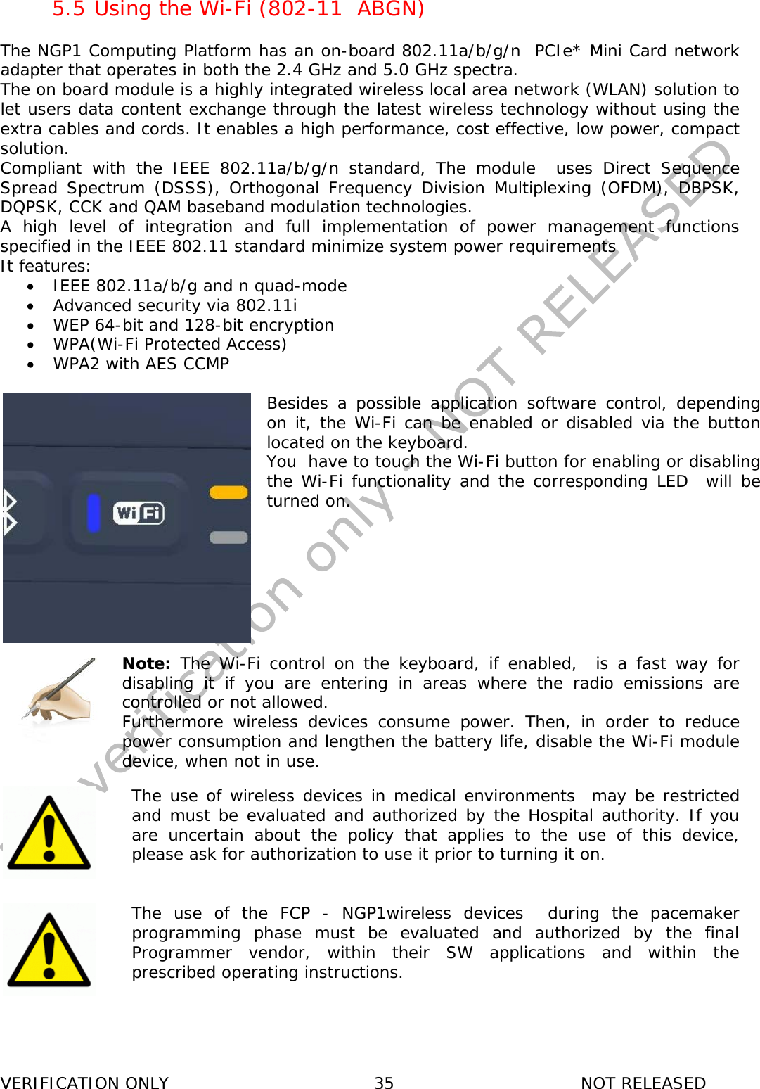
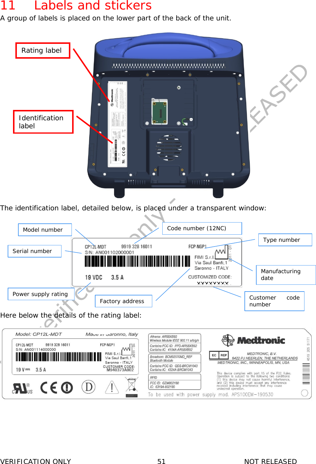
![VERIFICATION ONLY 9 NOT RELEASED • When you move the NGP1 Computing Platform between environments with very different humidity and/or temperature ranges, allow sufficient time to adjust to the new humidity or temperature. • Do not use the NGP1 Computing Platform AC adapter for other equipment. This can generate heat or fire. • Do not use other AC adapters with the NGP1 Computing Platform rather than the one supplied with it. • When using a display for long and continuous periods of time, rest your eyes for approximately five minutes every hour. Failing to rest your eyes can cause eye strain, headaches and other discomforts. 1.4 FCC notice Any change or modification not expressly approved by the party responsible for compliance could void the user’s authority to operate this equipment This equipment has been tested and found to comply with the limits for a Class B digital device, pursuant to Part 15 of the FCC Rules. These limits are designed to provide reasonable protection against harmful interference in a residential installation. This equipment generates, uses and can radiate radio frequency energy and, if not installed and used in accordance with the instructions, may cause harmful interference to radio communications. However, there is no guarantee that interference will not occur in a particular installation. If this equipment does cause harmful interference to radio or television reception, which can be determined by turning the equipment off and on, the user is encouraged to try to correct the interference by one or more of the following measures: -- Reorient or relocate the receiving antenna. -- Increase the separation between the equipment and receiver. -- Connect the equipment into an outlet on a circuit different from that to which the receiver is connected. -- Consult the dealer or an experienced radio/TV technician for help. 1.4.1 Cables Connections to this device must be made with shielded signals cables with metallic RFI/EMI connector hoods to maintain compliance with FCC Rules and Regulations. 1.5 FCC Radiation Exposure Statement This equipment complies with FCC radiation exposure limits set forth for an uncontrolled environment . End users must follow the specific operating instructions for satisfying RF exposure compliance. Please follow the operation instructions in this manual to maintain compliance with FCC RF exposure requirements. This RFID equipped computing platform meets FCC RF exposure guidelines when used in handheld or desktop situation 1.6 Industry Canada notice This device complies with Industry Canada licence-exempt RSS standard(s). Operation is subject to the following two conditions: (1) this device may not cause interference, and (2) this device must accept any interference, including interference that may cause undesired operation of the device. This Class [B] digital apparatus complies with Canadian ICES-003. Cet appareil numérique de la classe [B] est conforme à la norme NMB-003 du Canada. Le présent appareil est conforme aux CNR d'Industrie Canada applicables aux appareils radio exempts de licence. L'exploitation est autorisée aux deux conditions suivantes : (1) l'appareil ne doit pas produire de brouillage, et (2) l'utilisateur de l'appareil doit accepter tout brouillage radioélectrique subi, même si le brouillage est susceptible d'en compromettre le fonctionnement.](https://usermanual.wiki/Fimi-Srl/802180/User-Guide-1544677-Page-9.png)