Fine Offset Electronics WH31B Wireless weather station (Transmitter) User Manual
Fine Offset Electronics Co., Ltd. Wireless weather station (Transmitter) Users Manual
Users Manual
WiFi 8-Channel Wireless Thermo-Hygrometer User Manual
Table of Contents
1.Introduction ..................................................................................................................................... 2
2.Getting Started ................................................................................................................................ 2
2.1Parts List ................................................................................................................................. 2
2.2Indoor / Outdoor Thermo-Hygrometer Setup ......................................................................... 2
2.3Sensor Placement .................................................................................................................... 4
2.4Best Practices for Wireless Communication ........................................................................... 5
2.5Display Console ...................................................................................................................... 6
2.6Display Console Probe ............................................................................................................ 7
3.Display Console Operation ............................................................................................................. 8
3.1Screen Display ........................................................................................................................ 8
3.2Console Initialization ............................................................................................... 8
3.2.1Button Operation ............................................................................................................. 9
3.3Set Mode ............................................................................................................................... 10
3.3.1Time Zones .................................................................................................................... 11
3.3.2Auto Set Time ............................................................................................................... 12
3.3.3Setting Time Alarm ....................................................................................................... 12
3.4Max/Min Mode ..................................................................................................................... 12
3.4.1Viewing Max/Min Values .............................................................................................. 13
3.5Multiple Channels and Scroll Mode...................................................................................... 13
3.6Resynchronize Wireless Sensor ............................................................................................ 13
3.7Backlight Operation .............................................................................................................. 13
3.7.1With AC Adapter ........................................................................................................... 13
3.7.2Without AC Adapter ...................................................................................................... 13
4.Live Internet Publishing ................................................................................................................ 13
4.1Connecting the Weather Station Console to Wi-Fi ................................................................ 14
4.1.1Download mobile application ....................................................................................... 14
4.1.2Put console in Wi-Fi setup mode ................................................................................... 14
4.1.3Connect mobile device to EasyWeather Wi-Fi .............................................................. 14
4.1.4Register a Personal Weather Station (PWS) with wunderground.com .......................... 15
4.1.5Activate setup application ............................................................................................. 15
4.2Registering with and using wunderground.com .................................................................... 19
4.2.1Viewing data on wunderground.com ............................................................................. 21
4.3Registering with and using Weathercloud ............................................................................. 23
4.4Registering with Weather Observations Website (WOW) .................................................... 24
4.4.1Sign up with WOW ....................................................................................................... 24
4.4.2Confirm email with WOW ............................................................................................ 25
4.4.3Login with WOW .......................................................................................................... 25
4.4.4Create/Set up a new WOW site ..................................................................................... 25
4.4.5Entering WOW information in the mobile application ................................................. 27
4.5Mobile application – Check weather data and graph ............................................................ 27
4.6Mobile application – Remove monitoring WU ID ................................................................ 28
4.7Mobile application – Set Units .............................................................................................. 28
5.Glossary of Terms ......................................................................................................................... 29
6.Specifications ................................................................................................................................ 30
6.1Wireless Specifications ......................................................................................................... 30
6.2Measurement Specifications ................................................................................................. 31
6.3Power Requirements ............................................................................................................. 31
7.Troubleshooting Guide .................................................................................................................. 31
8.Liability Disclaimer ...................................................................................................................... 32
©Copyright 2018. Page 1

1. Introduction
Thank you for your purchase of the WiFi Wireless Thermo-Hygrometer. The following user guide
provides step by step instructions for installation, operation and troubleshooting.
2. GettingStarted
TheWiFi Wireless Thermo-Hygrometer consists of an indoor display console (receiver + WiFi
transmitter) and an indoor / outdoor thermo-hygrometer.
2.1 PartsList
QTY Item
1 Display Console
Dimensions (LxHxW): 67.5 x 90 x 26.8 mm (2.65 x 3.54 x 1.06”)
1 Thermo-hygrometer transmitter (WH31)
Dimensions (LxHxW): 122 x 40 x 18 mm (4.80 x 1.57 x 0.71”)
1 5V DC Adaptor
1 User manual
2.2 Indoor/OutdoorThermo‐HygrometerSetup
Note: Do not use rechargeable batteries. We recommend fresh alkaline batteries for outdoor
temperature ranges between -20 °C and 60 °C and fresh lithium batteries for outdoor temperature
ranges between -40 °C and 60 °C.
©Copyright 2018. Page 2
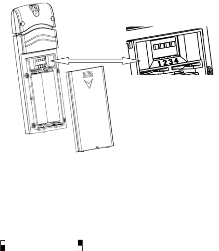
1. Remove the battery door on the back of the transmitter(s) by sliding down the battery door, as
shown in Figure 1 .
Figure 1
2. BEFORE inserting the batteries, locate the dip switches on the inside cover of the lid of the
transmitter.
3. Channel Number: This device supports up to eight transmitters, and includes three
transmitters. To set each channel number (the default is Channel 1), change Dip Switches 1, 2
and 3, as referenced in Figure 2.
4. Temperature Units of Measure: To change the transmitter display units of measure (°F
vs. °C), change Dip Switch 4, as referenced in Figure 2.
Switch in down position. Switch in up position.
©Copyright 2018. Page 3
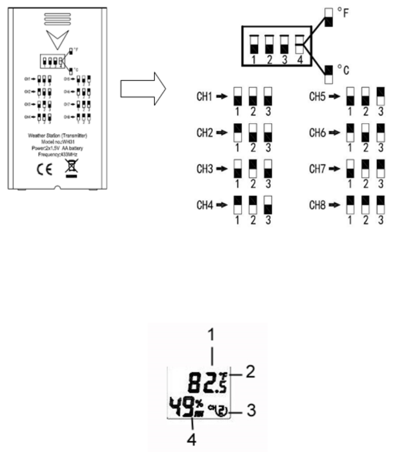
Figure 2
5. Insert two AA batteries.
6. Verify the correct channel number (CH) and temperature units of measure (°F vs. °C) are on
the display, as shown in Figure 3.
Figure 3
(1)
temperature
(2) temperature units (°F vs. °C)
(3) channel number
(4) relative humidity
7. Close the battery door.
8. Repeat for the additional remote transmitters, verifying each remote is on a different channel.
2.3 SensorPlacement
It is recommended you mount the remote sensor outside on a north facing wall, in a shaded area, at a
height at or above the receiver. If a north facing wall is not possible, choose a shaded area, under an
eve.
Direct sunlight and radiant heat sources will result in inaccurate temperature readings. Although the
sensor is weatherproof, it is best to mount in a well-protected area, such as an eve.
©Copyright 2018. Page 4
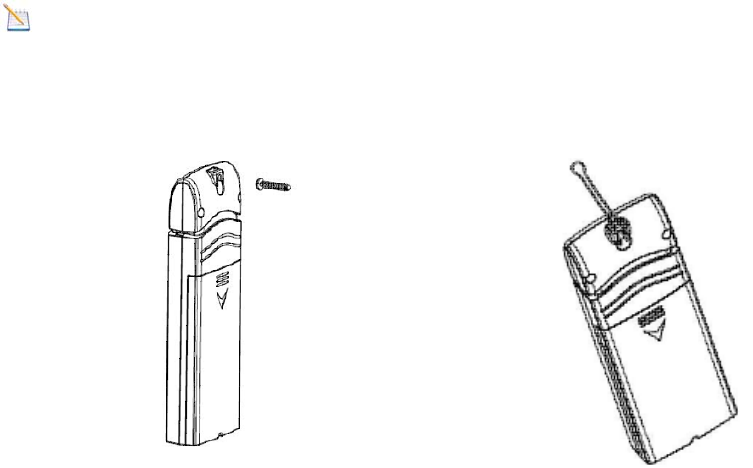
1. Use a screw or nail to affix the remote sensor to the wall, as shown in Figure 4.
2. Hang the remote sensor up on string or zip tie, as shown in Figure 5.
Note: Make sure the sensor is mounted vertically and not lying down on a flat surface. This will
insure optimum reception. Wireless signals are impacted by distance, interference (other weather
stations, wireless phones, wireless routers, TVs and computer monitors), and transmission barriers,
such as walls. In general, wireless signals will not penetrate solid metal and earth (down a hill, for
example).
Figure 4 Figure 5
2.4 BestPracticesforWirelessCommunication
Wireless communication is susceptible to interference, distance, walls and metal barriers. We
recommend the following best practices for trouble free wireless communication.
1. Electro-Magnetic Interference (EMI). Keep the console several feet away from computer
monitors and TVs.
2. Radio Frequency Interference (RFI). If you have other 915 MHz devices and
communication is intermittent, try turning off these other devices for troubleshooting
purposes. You may need to relocate the transmitters or receivers to avoid intermittent
communication.
3. Line of Sight Rating. This device is rated at 300 feet line of sight (no interference, barriers or
walls) but typically you will get 100 feet maximum under most real-world installations,
which include passing through barriers or walls.
4. Metal Barriers. Radio frequency will not pass through metal barriers such as aluminum
siding. If you have metal siding, align the remote and console through a window to get a clear
line of sight.
©Copyright 2018. Page 5
The following is a table of reception loss vs. the transmission medium. Each “wall” or obstruction
decreases the transmission range by the factor shown below.
Medium RF Signal Strength Reduction
Glass (untreated) 5-15%
Plastics 10-15%
Wood 10-40%
Brick 10-40%
Concrete 40-80%
Metal 90-100%
2.5 DisplayConsole
(1) Connect the display console power jack to AC power adapter with the included power adapter,
as shown in Figure 6a.
(2) Remove the battery door on the back of the console, and insert 2xAAA batteries per Figure
6b.
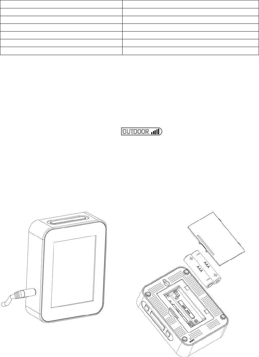
(3) Wait several minutes for the remote sensor(s) to synchronize with the display console. Make
sure the remote sensor is powered up and about 5 to 10 feet away while waiting for
synchronization. The remote search icon will be present while searching.
If you have more than one sensor, the channel number will displayed next to the remote
search icon.
Do not touch any buttons until the remote sensor(s) report in, otherwise the remote sensor
search mode will be terminated and the search icon will turn off. When the remote sensor has
been received, the console will automatically switch to the normal mode, and all further
settings can be performed.
(a) (b)
©Copyright 2018. Page 6
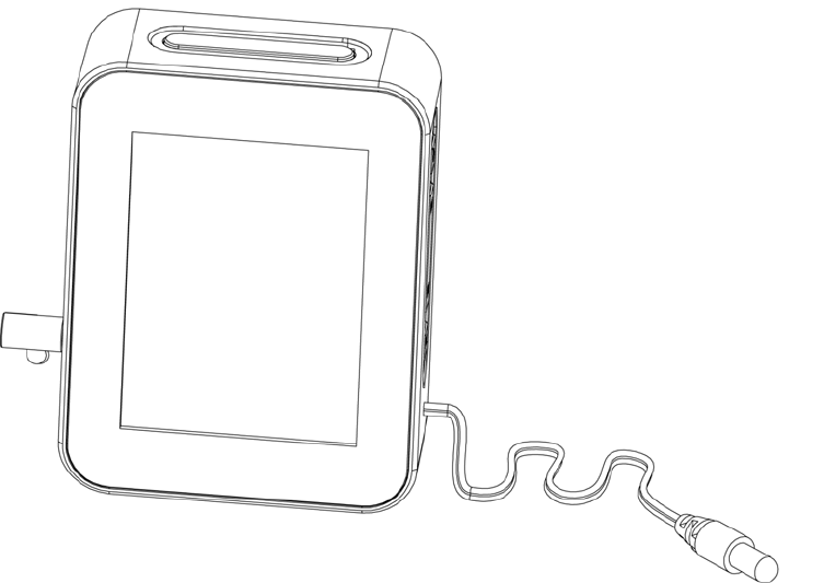
Figure 6
2.6 DisplayConsoleProbe
The display console includes a 90 cm (about 3 feet) dry probe to accurately measure air temperature,
since the console generates heat. The probe should not be touching any surface to accurately measure
air temperature.
Figure 7
©Copyright 2018. Page 7
3. DisplayConsoleOperation
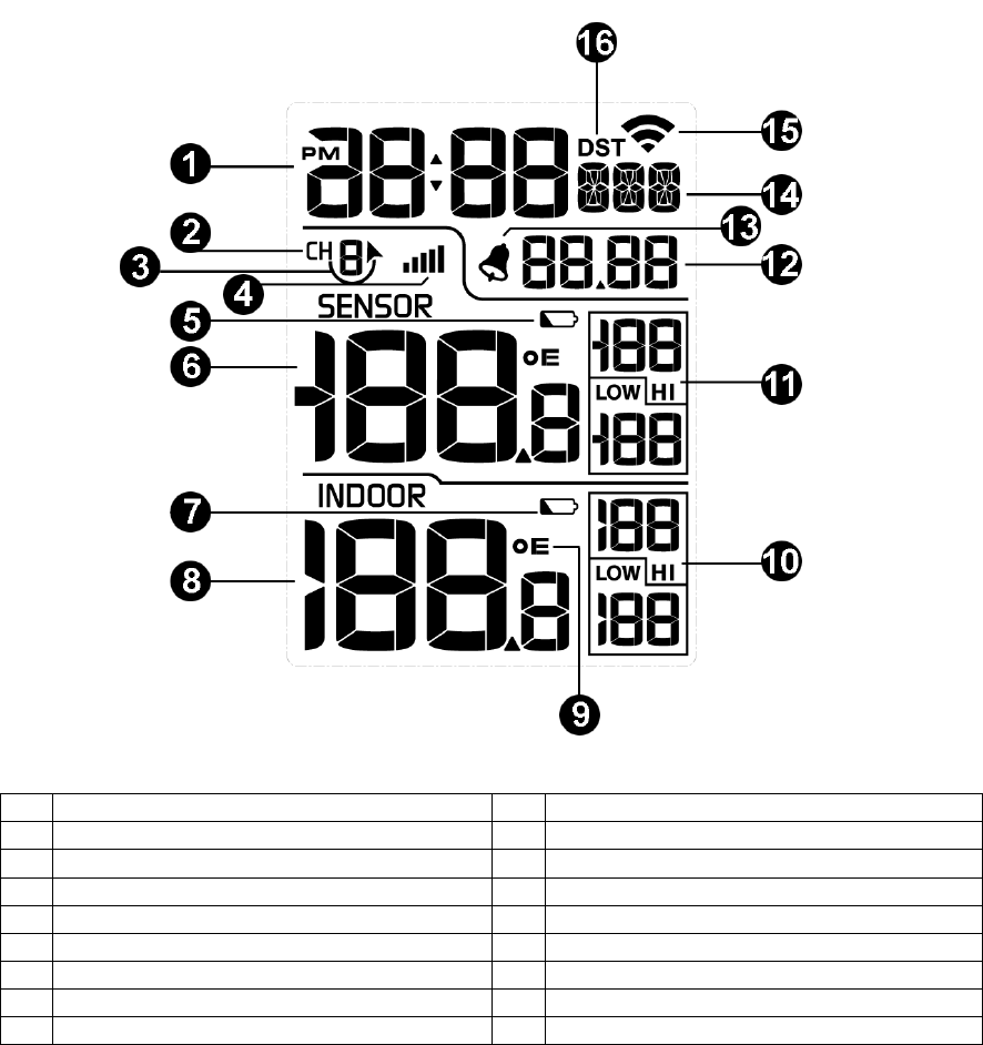
3.1 ScreenDisplay
The display console home screen layout is shown in Figure 8.
Figure 8
No Description No Description
1 Time 9 Temperature Units of Measure
2 Sensor Channel Number 10 Indoor Hi/Low Temperature
3 Sensor Scroll Icon 11 Sensor Hi/Low Temperature
4 RF Reception 12 Date
5 Sensor Low Battery Indicator 13 Alarm icon
6 Sensor Temperature 14 Day of Week
7 Indoor Low Battery Indicator 15 WIFI icon
8 Indoor Temperature 16 DST
3.2 ConsoleInitialization
After the console is connected to AC power, the console will display the software version number two
seconds after power up, as shown in Figure 9.
©Copyright 2018. Page 8
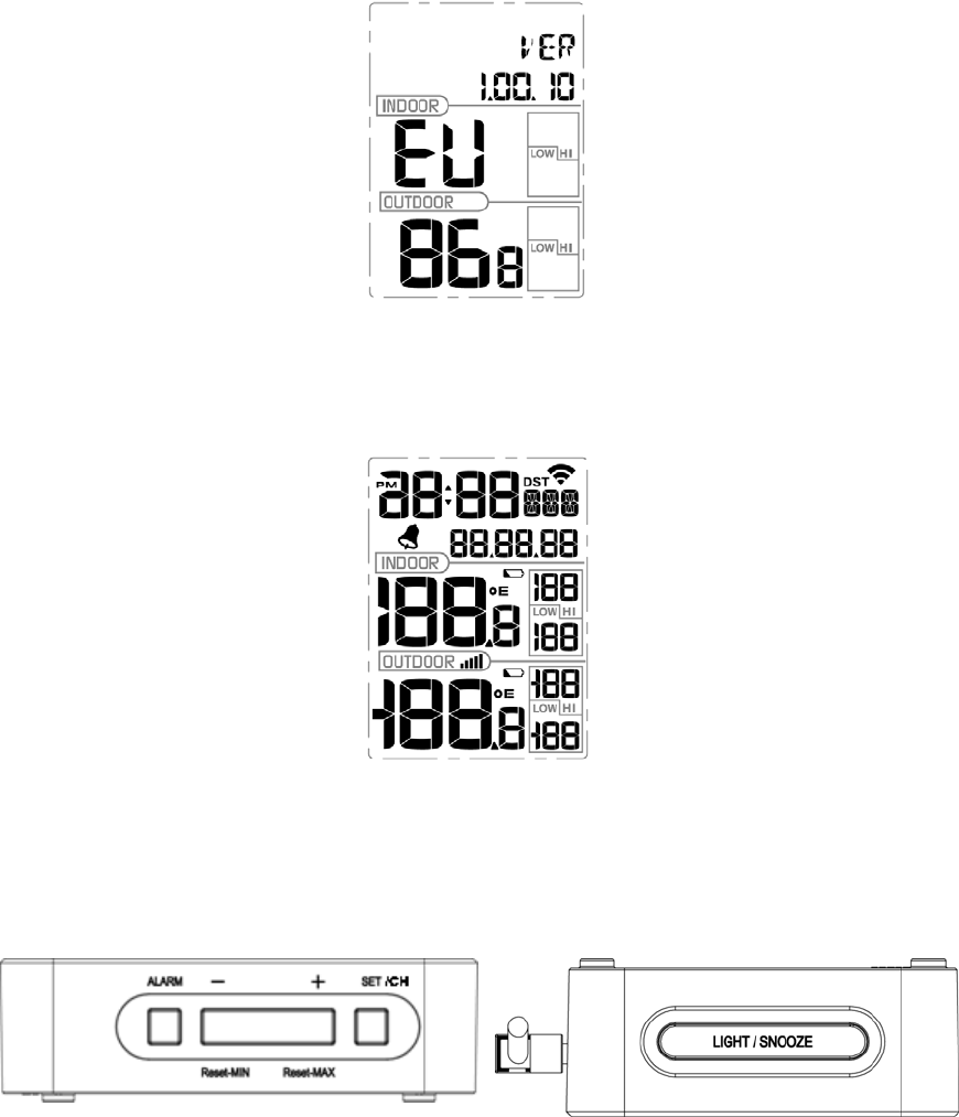
Figure 9
The console will display all of the LCD segments for three seconds after power up as shown in Figure
10, the indoor conditions will immediately update, and the remote sensors array will register within a
few minutes.
Figure 10
3.2.1 ButtonOperation
The operation buttons are on the side and top of the console, as shown in Figure 11:
(a) ALARM, -/Reset-MIN, +/Reset-MAX, SET/CH
(b) LIGHT / SNOOZE
(a) Side View (b) Top View
Figure 11
©Copyright 2018. Page 9

The console has 5 buttons at the bottom for easy operation:
Key Description
SET/CH • Press the SET/CH button to change between channels 1-8.
• Press and hold the SET/CH button for two seconds to enter Set
Mode.
+ / Reset-MAX • Press the + / Reset-MAX button for five seconds, and the maximum
indoor and outdoor temperature will reset to the current value on the
display console.
• While in SET mode, press to increase the value. Press and hold for
two seconds to increase the value rapidly.
- / Reset-MIN • Press the - / Reset-MIN button for five seconds, and the minimum
indoor and outdoor temperature will reset to the current value on the
display console.
• While in SET mode, press to decrease the value. Press and hold for
two seconds to decrease the value rapidly.
ALARM • Press and release the ALARM button to enter alarm mode.
• Press and hold the ALARM button for two seconds to enter the
alarm setting mode.
LIGHT/SNOOZE • When connected to AC power, press and hold for three seconds to
turn on backlight permanently. With the backlight turned on, press
and hold for five seconds to turn off the backlight.
• When powered by batteries, press to turn on the backlight for 3
seconds.
3.3 SetMode
Press and hold the SET/CH button for two seconds to enter the SET Mode. To proceed to the next
setting, press (do not hold) the SET/CH button.
To exit the SET mode at any time, press the LIGHT / SNOOZE button.
Figure 12 summarizes the set mode sequence and commands.
©Copyright 2018. Page 10

Command Mode Description Settings
SET/CH +
2 seconds BEEP Turns on or off the beep with each
keystroke. Press +/Reset-MAX to toggle OFF
and ON
SET/CH DST Observe Daylight Savings Time (set to
OFF in Arizona and Hawaii, ON
everywhere else)
Press +/Reset-MAX to toggle OFF
and ON
SET/CH ZON Time Zone (TZ) Press +/Reset-MAX to increase or
-/Reset-MIN to decrease
(reference Figure 13).
SET/CH 12H 12/24 Hour Format Press +/Reset-MAX to toggle
between 12 hour (12h) and 24 hour
(24h) format
SET/CH HR Hour of Day Press +/Reset-MAX to increase or
-/Reset-MIN to decrease
SET/CH MIN Minute of Day Press +/Reset-MAX to increase or
-/Reset-MIN to decrease
SET/CH M-D Month Day Format Press +/Reset-MAX to toggle
between M-D (month/day) format
and D-M (day/month) format
SET/CH Y Year Press +/Reset-MAX to increase or
-/Reset-MIN to decrease
SET/CH M Month of Year Press +/Reset-MAX to increase or
-/Reset-MIN to decrease
SET/CH D Day of Month Press +/Reset-MAX to increase or
-/Reset-MIN to decrease
SET/CH °F Temperature Units of Measure Press +/Reset-MAX to toggle
between °F and °C
SET/CH Exit Set Mode
SET/CH + 2 seconds means press and hold the SET/CH button for two seconds.
SET/CH means press the SET/CH button. Figure 12
3.3.1 TimeZones
The following table summarizes time zones around the world.
Hours from
GMT Time Zone Cities
-12 IDLW: International Date Line West ---
-11 NT: Nome Nome, AK
-10 AHST: Alaska-Hawaii Standard
CAT: Central Alaska
HST: Hawaii Standard
Honolulu, HI
-9 YST: Yukon Standard Yukon Territory
-8 PST: Pacific Standard Los Angeles, CA, USA
-7 MST: Mountain Standard Denver, CO, USA
-6 CST: Central Standard Chicago, IL, USA
-5 EST: Eastern Standard New York, NY, USA
-4 AST: Atlantic Standard Caracas
-3 --- São Paulo, Brazil
-2 AT: Azores Azores, Cape Verde Islands
-1 WAT: West Africa ---
0 GMT: Greenwich Mean London, England
©Copyright 2018. Page 11

Hours from
GMT Time Zone Cities
WET: Western European
1 CET: Central European Paris, France
2 EET: Eastern European Athens, Greece
3 BT: Baghdad Moscow, Russia
4 --- Abu Dhabi, UAE
5 --- Tashkent
6 --- Astana
7 --- Bangkok
8 CCT: China Coast Bejing
9 JST: Japan Standard Tokyo
10 GST: Guam Standard Sydney
11 --- Magadan
12 IDLE: International Date Line East
NZST: New Zealand Standard Wellington, New Zealand
Figure 13
3.3.2 AutoSetTime
When the console is connected to WiFi and the Internet, the time will automatically set.
3.3.3 SettingTimeAlarm
To view the alarm time, press the ALARM button.
Press and hold the ALARM button for two seconds to enter the ALARM Set Mode. To save and
proceed to the next alarm setting, press (do not hold) the SET/CH button.
To exit the alarm mode at any time, press the LIGHT / SNOOZE button.
The time alarm will sound for 120 seconds, and can be disabled by pressing the LIGHT / SNOOZE
button.
Figure 14 summarizes the alarm mode sequence and commands.
Command Mode Settings
ALARM
+ 2
seconds
Turns alarm ON or
OFF Press +/Reset-MAX to toggle OFF and ON
When the alarm is on, the alarm time icon will appear.
SET/CH Alarm Hour Press +/Reset-MAX to increase or -/Reset-MIN to decrease
SET/CH Alarm Minute Press +/Reset-MAX to increase or -/Reset-MIN to decrease
SET/CH Exit alarm settings mode.
ALARM + 2 seconds means press and hold the ALARM button for two seconds.
SET/CH means press the SET/CH button. Figure 14
3.4 Max/MinMode
The minimum and maximum temperature values are displayed on the console for the past 24 hours.
©Copyright 2018. Page 12

3.4.1 ViewingMax/MinValues
Press the + / Reset-MAX button for five seconds, and the maximum indoor and outdoor temperature
will reset to the current value on the display console.
Press the - / Reset-MIN button for five seconds, and the minimum indoor and outdoor temperature
will reset to the current value on the display console.
3.5 MultipleChannelsandScrollMode
If you have multiple wireless sensors, while in normal mode, press the SET/CH button to the different
channels. Temperature, humidity, and MAX/MIN records will be displayed for each channel.
To scroll automatically, press the SET/CH button again, and the scroll icon will be displayed
next to the channel number, and will scroll every 5 seconds.
3.6 ResynchronizeWirelessSensor
Press and hold the +/Reset-MAX and -/Reset-MIN buttons at the same time for five seconds, and the
display will search for a new transmitter for three minutes. Dashes will be displayed in the outdoor
temperature field.
Alternately, you can power down and up the console by removing AC power and batteries.
3.7 BacklightOperation
3.7.1 WithACAdapter
The backlight can only be continuously on when the AC adapter is permanently on. When the AC
adapter is disconnected, the backlight can be temporarily turned on.
Press the LIGHT SNOOZE button to adjust the brightness between High, Low and Off.
3.7.2 WithoutACAdapter
To reduce power consumption, the console will sleep on battery power only, and will not send data to
the Internet.
To temporarily turn on the back light for 15 seconds, press the LIGHT SNOOZE button.
4. LiveInternetPublishing
The WS-0265 sends data to three free hosting services:
Hosting Service Website Description
Weather Undergound https://www.wunderground.com
and IBM.
Weather Underground is a free weather
hosting service that allows you to send and
view your weather station data real-time,
view graphs and gauges, import text data
for more detailed analysis and use iPhone,
iPad and Android applications available at
Wunderground.com. Weather Underground
is a subsidiary of The Weather Channel
©Copyright 2018. Page 13
WOW http://wow.metoffice.gov.uk/ UK based weather observation WOW is a
website.
Weather Cloud https://weathercloud.net loud is a real-time weather social Weatherc
network formed by observers from around
the world.
he WS-0265 weather station sends data to the Internet using your WiFi connection.
4.1 ConnectingtheWeatherStationConsoletoWi‐Fi
the internet via
setup with the outdoor sensor package nearby and indoor,
4.1.1 Downloadmobileapplication
evice, either iOS or Android. Start by
4.1.2 PutconsoleinWi‐Fisetupmode
the console if you have not already
T
To send weather data to these services you must connect your console to
Wi-Fi. The console can only operate using Wi-Fi when the external power adapter is
connected and plugged in!
Note: If you are testing the
you may want to consider connecting to Wi-Fi, but not yet configuring any of the
weather services. The reason is that while indoor the temperatures and humidity
recorded by the outdoor sensor, and as reported to the weather service(s) will
reflect indoor conditions, and not outdoor conditions. Therefore, they will be
incorrect. Furthermore, the rainfall bucket may be tripped during handling, causing
rain to register while it may not actually have been raining. One way to prevent this
is to follow all instructions, except to use an incorrect password, on purpose! Then,
after final outdoor installation, come back and change the password after clearing
console history. That will start uploading to the services with a clean slate.
Wi-Fi configuration is done using your mobile d
downloading the “WS View” application from the Apple App Store or Google Play store, as
appropriate for your device.
Plug in the external power adapter and connect to
done so. Next, press and hold the GRAPH and MENU buttons simultaneously for five
seconds. The Wi-Fi icon ( ) in the top-right of the display will start flashing to indicate the
console is waiting for Wi-Fi configuration. The console will now have activated a Wi-Fi
network named starting with “EasyWeather Wi-Fi” and you will connect to it with your
mobile device.
4.1.3 Connectmobiledev icetoEasyWeatherWi‐Fi
droid, Wi-Fi for iOS
Using your phone’s Wi-Fi setup capabilities (WLAN setup for An
devices), connect your phone to the EasyWeather network now advertised by the console.
For Android users:
©Copyright 2018. Page 14
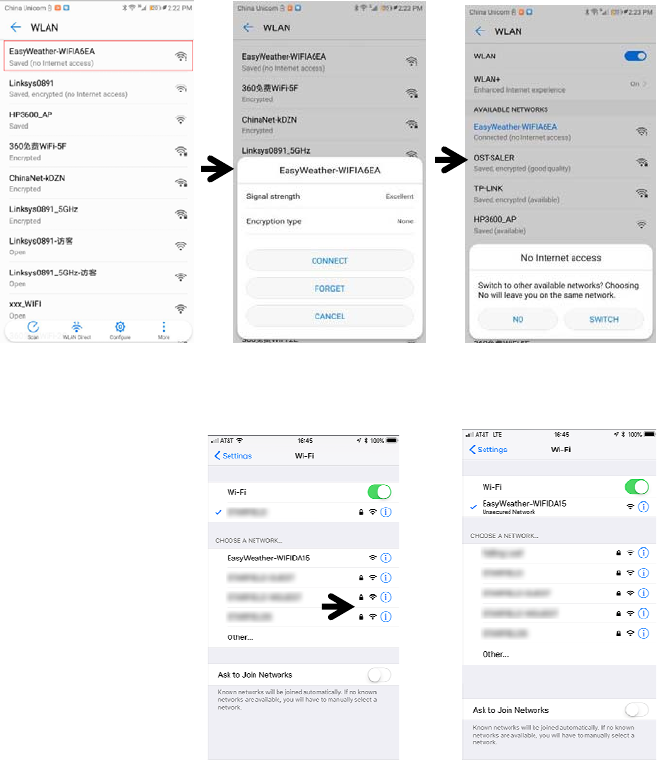
Answer “NO” to the “No Internet access” message!
For iOS users:
Look for the network named “EasyWeather-WIFI” followed by four characters. Tap on it to
connect to that network. You will see a warning “Unsecured Network” under the name of
the “EasyWeather-WIFI” network. This is normal and can be ignored.
4.1.4 RegisteraPersonalWeatherStation(PWS)with
wunderground.com
If you are planning to use wunderground.com you must have an account and register a
(new) personal weather station. You may do so on the wunderground.com web site, or
you can do this from within the mobile app. Take note of the PWS identifier (ID) and the
password that will be generated for you.
4.1.5 Activatesetupapplication
Now activate the application you have downloaded on your mobile device. The following
instructions will generally show screen shots for the Android application side by side with
the iOS version, or iOS below Android when there is not enough space for side by side.
©Copyright 2018. Page 15
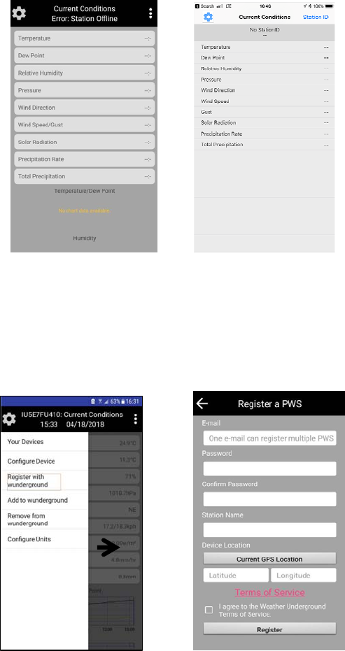
Figure 15: Mobile application – Main screen (Android & iOS)
The main screen will indicate your station is off-line (because it is not yet connected to
Wi-Fi). At this point, if you have not already done so, you can register on
wunderground.com and create your PWS by pressing on the settings icon and activating
the “Register with wunderground” option. Fill out the form and take note of the station ID
and password.
Figure 16: Mobile application – wunderground.com registration (Android)
©Copyright 2018. Page 16
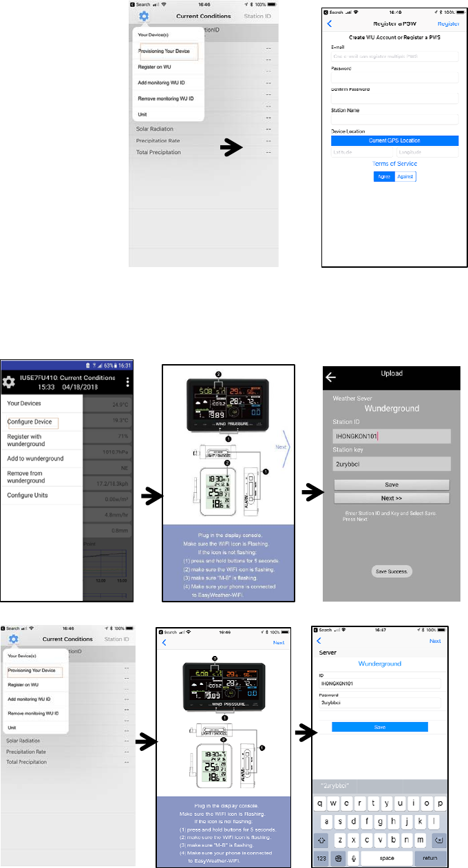
Figure 17: Mobile application - wunderground.com registration (iOS)
Next, tap on the settings icon and select “Configure Device”. You will be shown some
instructions to read. Press “Next” when ready. You will then be asked for the
wunderground.com station ID and password. If you are not planning to use
wunderground.com, you may leave this form blank, otherwise enter them and click “Save.”
Figure 18: Mobile application – Provisioning device (Android)
Figure 19: Mobile application – Provisioning device (iOS)
©Copyright 2018. Page 17
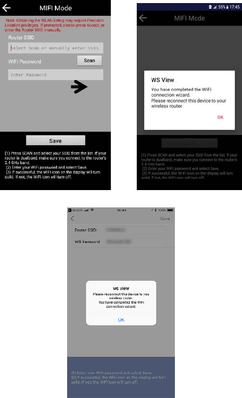
After entering the wunderground.com information (or leaving it blank), tap “Next” and you
will be presented with the Wi-Fi mode page. Here you will enter the name of the Wi-Fi
network (SSID) you want the console to connect to for Internet access, as well as its
password (if applicable). You may also scan for available networks.
Figure 20: Mobile application – Connect to your Wi-Fi network (Android)
Figure 21: Mobile application – Connect to your Wi-Fi network (iOS)
After entering your Wi-Fi network details, the console will discontinue the EasyWeather
Wi-Fi network and connect to your “normal” network. It will also start sending weather data
to wunderground.com if you configured it.
Your mobile device may still be configured for the EasyWeather network, or it may have
already switched to another available network. Check and make sure your mobile device
is now configured for the same network that you configured on the console, so the mobile
application can reach the console again.
You should now be able to see your console through the “Your Device(s)” menu option:
©Copyright 2018. Page 18
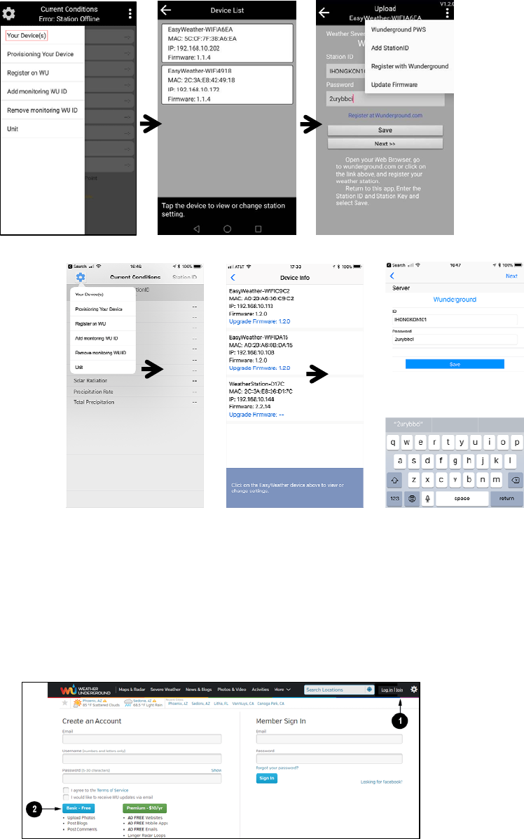
Figure 22:
Mobile application – Your devices (Android)
Figure 23: Mobile application – Your devices (iOS)
Tapping on your console’s entry in the device list will bring you to the page where you can
change WU registration information, or update firmware.
4.2 Registeringwithandusingwunderground.com
If you have not already done setup for wunderground.com during the Wi-Fi setup, you can
do so later. Perform the following steps:
1. Visit Wunderground.com and select the Join link (1) at the top of the page and select
the Free (2) sign up option.
©Copyright 2018. Page 19
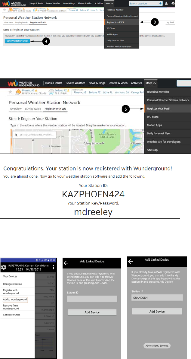
2. Select More | Register Your PWS (3)
3. Click Send Validation Email (4). Respond to the validation email from
Wunderground.com (it may take a few minutes).
4. Select More | Register Your PWS (5) again. This time you will be asked details about
your weather station. Go ahead and fill out the form
After completing the weather station, you will see something like this:
Your station ID will have the form: KSSCCCC###, where K is for USA station (I for
international), SS is your state, CCCC is an abbreviation for your city and ### is the
station number in that city. In the example above, you see station 424 in the state of
Arizona (AZ) in the United States (K).
5. Take note of the station ID and key/password and enter it in the mobile application:
©Copyright 2018. Page 20
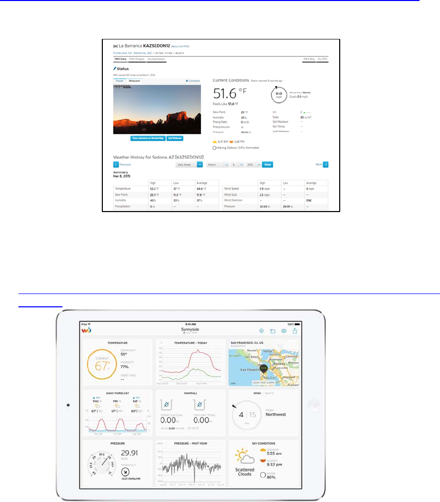
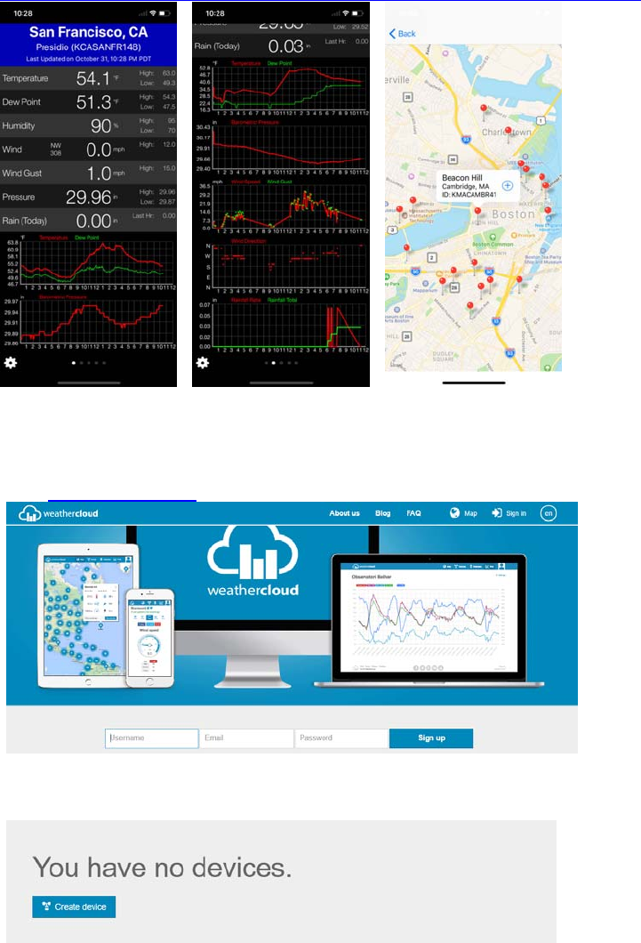
4.2.1 Viewingdataonwunderground.com
The most basic way to observe your weather station’s data is by using the
wunderground.com web site. You will use a URL like this one, where your station ID
replaces the text “STATIONID”:
http://www.wunderground.com/personal-weather-station/dashboard?ID=STATIONID
It will show a page such as this, where you can look at today’s data and historical data as
well:
Figure 24: Sample wunderground.com PWS page
There are also some very useful mobile apps. The URLs provided here go to the Web
version of the application pages. You can also find them directly from the iOS or Google
Play stores:
• WunderStation: iPad application for viewing your station’s data and graphs
https://itunes.apple.com/us/app/wunderstation-weather-from-your-neighborhood/id90
6099986
• WU Storm: iPad and iPhone application for viewing radar images, animated wind,
cloud coverage and detailed forecast, and PWS station data
©Copyright 2018. Page 21
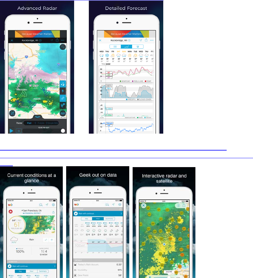
https://itunes.apple.com/us/app/wu-storm/id955957721
• Weather Underground: Forecast: iOS and Android application for forecasts
https://itunes.apple.com/us/app/weather-underground-forecast/id486154808
https://play.google.com/store/apps/details?id=com.wunderground.android.weather&h
l=en
• PWS Weather Station Monitor: View weather conditions in your neighborhood, or
even right in your own backyard. Connects to wunderground.com
©Copyright 2018. Page 22
https://itunes.apple.com/us/app/pws-weather-station-monitor/id713705929
4.3 RegisteringwithandusingWeathercloud
To register with Weathercloud follow these steps:
1. Visit weathercloud.net and enter a Username, Email and Password to sign up.
2. Respond to the validation email from Weathercloud (it may take a few minutes).
3. You will then be prompted to add a device/ Select “Create device” and enter your
station’s information:
4. After registering your station, take note of the “Weathercloud ID” and “Key” presented
to you.
5. Enter these values in the mobile application:
©Copyright 2018. Page 23
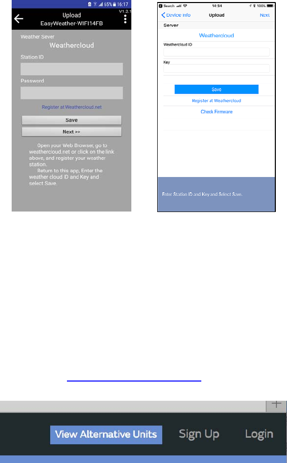
Figure 25: Mobile application – Weathercloud configuration
4.4 RegisteringwithWeatherObservationsWebsite(WOW)
To have your weather station upload data to the Met Office’s WOW site you will need to
complete the following steps:
1. Sign Up with WOW
2. Confirm your email with WOW
3. Login to WOW
4. Create/Set up a new WOW site
4.4.1 SignupwithWOW
Navigate your browser to http://wow.metoffice.gov.uk. On the top-right side of the
resulting page you will see menu options. Click “Sign Up”.
Figure 26: WOW Signup menu
You will be presented with the screen below where you will choose to either create a new
account or use an already existing account. Click the desired option.
©Copyright 2018. Page 24
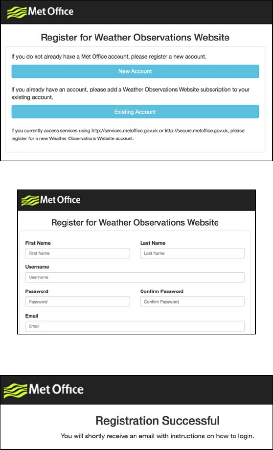
Figure 27: WOW Registration account options
If you chose “New Account” you will be presented with a form to fill out:
Figure 28: WOW New account form
The actual form is longer, but all questions should be self-explanatory. Complete and
submit the form. You will receive the following notice on completion:
Figure 29: WOW Successful registration
4.4.2 ConfirmemailwithWOW
Now wait for the email to arrive and click the link in that email to confirm your email
address.
4.4.3 LoginwithWOW
Follow instructions on the screen and login to the site.
4.4.4 Create/SetupanewWOWsite
Once you are logged in you will need to create a new WOW site. “Sites” are the means by
which WOW organizes weather data the you contribute. Basically, WOW builds a
©Copyright 2018. Page 25
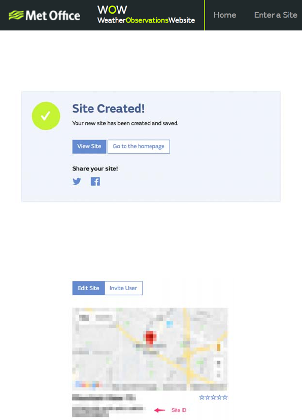
personal web site for your weather station. Associated with the web site is two items you
will need to allow uploading of data:
Site ID: This is an arbitrary number that is used to distinguish your site from another. This
number appears (in brackets) next to or underneath the name of your site on the site
information page, for example: 6a571450-df53-e611-9401-0003ff5987fd
Authentication Key: This is a 6-digit number that is used to ensure data is coming from
you and not another user.
Begin setting up a new site by clicking “Enter a Site”:
Figure 30: WOW New Site menu
You will be presented with a form where you detail your station’s location and a bunch of
other settings related to how you wish the site to operate. After you complete the setup,
you should see:
Figure 31: WOW Site Created
Make sure you are (still) logged in to the WOW site. Login as necessary. Now click on “My
Sites” in the navigation bar at the top. If you have only 1 site, you will now be shown its
page. If you have multiple, you will have to choose the correct one first. On this page, on
the right side you will find the site id just below the map:
Figure 32: WOW Site ID and Edit Site
You will also need to establish a unique 6 digits PIN code that you should keep secret. It is
the “Authentication Key.” Setup this number by clicking on “Edit Site”) (Figure 33) and
filling out the with a 6-digit number of your choice:
©Copyright 2018. Page 26
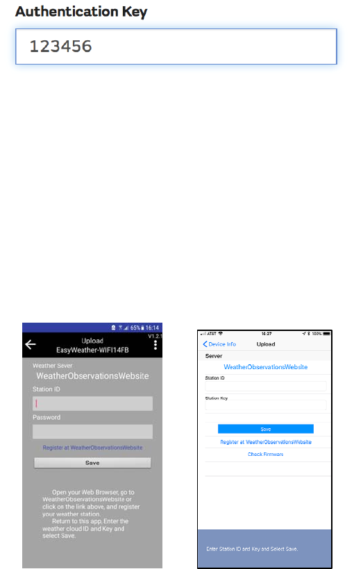
Figure 33: WOW Authentication Key
You will need both “Site ID” and “Authentication Key” to setup the upload configuration for WOW in
the mobile application.
4.4.5 EnteringWOWinformationinthemobileapplication
In your mobile application, navigate to the “Your Devices” page and tap on the device you
want to configure WOW for. You will then be shown the “wunderground.com”
configuration. Please ignore and tap “Next” to see the “Weathercloud” configuration.
Please press “Next” one more time and you will now be on the screen where you will
configure WOW.
On this screen you will fill out “Station ID” with the WOW “Site ID” value, and “Station Key”
with the WOW “Authentication Key” you created. Press “Save” to finalize the
configuration.
Figure 34: Mobile application – WOW Configuration
If you did everything correctly, data should be starting to upload to your WOW site. You
may want to go back to the “Edit” page and (re)configure some of the options so that it
shows everything to your liking.
4.5 Mobileapplication–Checkweatherdataandgraph
In the mobile application choose the station from the WU station list and you will be
presented with a page listing current conditions for that station.
©Copyright 2018. Page 27
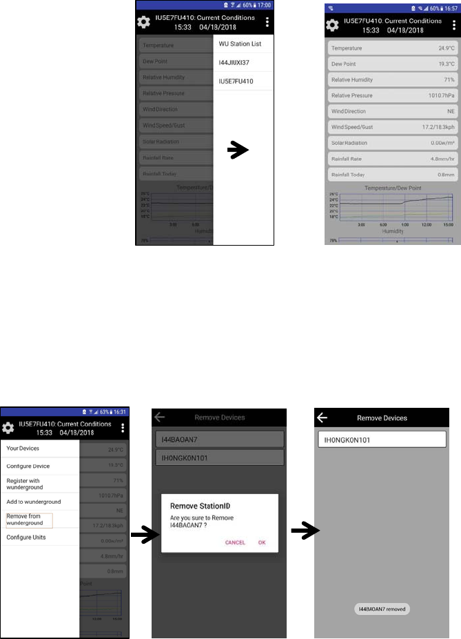
Figure 35: Mobile application – weather and data graph
4.6 Mobileapplication–RemovemonitoringWUID
If you have previously registered your console for use with wunderground.com and wish to
remove that, use the “Remove from wunderground” menu option after tapping on the
settings icon, select your console from the list and confirm you wish to remove the station
from wunderground.com services. Prior uploaded data will not be lost!
Figure 36: Mobile application – Remove monitoring WU ID
4.7 Mobileapplication–SetUnits
You may want to change the units in which sensor values are reported. To do so, click on
the “Configure Units” menu after tapping on the settings icon. Next, tap on the sensor type
you wish to change the reporting units for and set the units as desired.
©Copyright 2018. Page 28
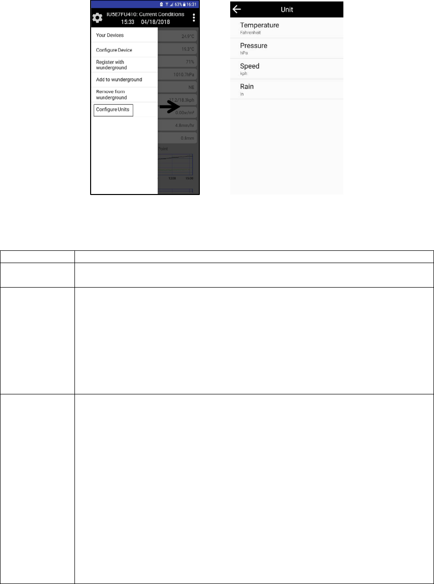
Figure 37: Mobile application – Change units
5. GlossaryofTerms
Term Definition
Accuracy Accuracy is defined as the ability of a measurement to match the actual value of the
quantity being measured.
Dew Point The dew point is the temperature at which a given parcel of humid air must be
cooled, at constant barometric pressure, for water vapor to condense into water. The
condensed water is called dew. The dew point is a saturation temperature.
The dew point is associated with relative humidity. A high relative humidity
indicates that the dew point is closer to the current air temperature. Relative
humidity of 100% indicates the dew point is equal to the current temperature and the
air is maximally saturated with water. When the dew point remains constant and
temperature increases, relative humidity will decrease.
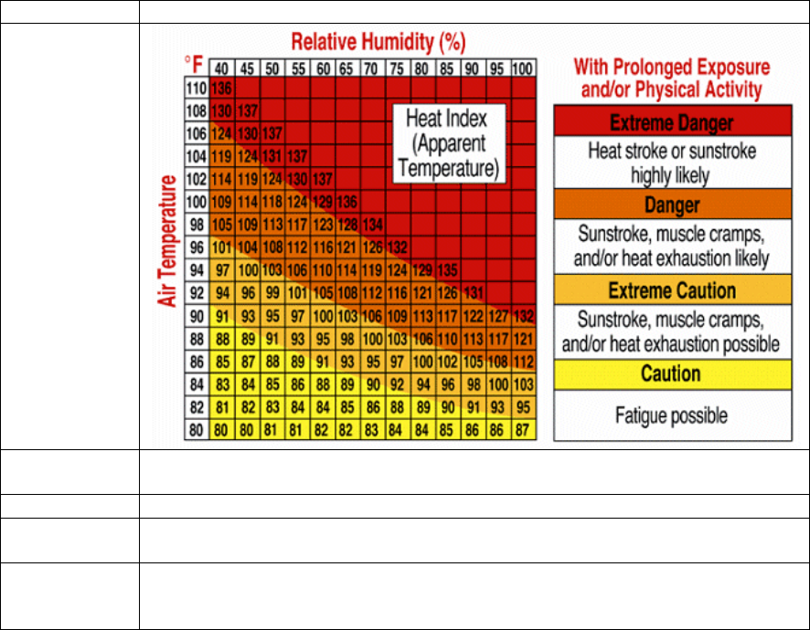
Heat Index The Heat Index, sometimes referred to as the apparent temperature, is a measure of
how hot it really feels when relative humidity is factored with the actual air
temperature.
To find the Heat Index temperature, look at the Heat Index chart below. As an
example, if the air temperature is 96°F and the relative humidity is 65%, the heat
index (how hot it feels) is 121°F.
IMPORTANT: Since heat index values were devised for shady, light wind
conditions, exposure to full sunshine can increase heat index values by up to 15°F.
Also, strong winds, particularly with very hot, dry air, can be extremely hazardous.
The Heat Index Chart shaded zone above 105°F shows a level that may cause
increasingly severe heat disorders with continued exposure or physical activity.
Heat Index is not calculated below 80°F.
©Copyright 2018. Page 29
Term Definition
Hygrometer A hygrometer is a device that measures relative humidity. Relative humidity is a
term used to describe the amount or percentage of water vapor that exists in air.
Range Range is defined as the amount or extent a value can be measured.
Resolution Resolution is defined as the number of significant digits (decimal places) to which a
value is being reliably measured.
Thermometer A thermometer is a device that measures temperature. Most digital thermometers are
resistive thermal devices (RTD). RTDs measure changes in temperature as a
function of electrical resistance.
Figure 38
6. Specifications
6.1 WirelessSpecifications
• Line of sight wireless sensor array RF transmission (in open air): 330 feet, 100 feet under
most conditions
• Line of sight WiFi RF transmission (in open air): 80 feet
• Update Rate: Outdoor Sensor: 48 seconds, Indoor Sensor: 64 seconds
• Sensor Array RF Frequency: 915 MHz
• WiFi Console RF Frequency: 2.4 GHz
©Copyright 2018. Page 30

6.2 MeasurementSpecifications
The following table provides the specifications for the measured parameters.
Measurement Range Accuracy Resolution
Indoor Temperature -14 to 140 °F
-10 to 60 °C ± 1.8 °F
± 1 °C 0.1 °F
0.1 °C
Outdoor Temperature -40 to 149 °F (lithium
batteries)
-23 to 140 °F (alkaline
batteries)
± 2 °F 0.1 °F
Outdoor Humidity 10 to 99% ± 5% (only guaranteed
between 20 to 90%) 1 %
Figure 39
6.3 PowerRequirements
• Base station : 5V DC Adaptor (included)
• Base station: 2 x AAA batteries (not included)
• Outdoor sensor array: 2xAA batteries (not included)
• About 12-24 months for thermometer-hygrometer sensor (use lithium batteries in cold
weather climates)
7. TroubleshootingGuide
Problem Solution
Wireless remote
(thermo-hygrometer)
not reporting in to
console.
There are dashes (--.-)
on the display console.
If any of the sensor communication is lost, dashes (--.-) will be displayed on
the screen. To reacquire the signal, reference Section 3.6.
The maximum line of sight communication range is 300 feet and 100 feet
under most conditions. Move the sensor closer to the display console.
If the sensor is too close (less than 5’), move the sensor away from the
display console.
Make sure the remote sensor LCD display is working on both the console
and the remote sensor.
Install a fresh set of batteries in the remote thermo-hygrometer. For cold
weather environments, install lithium batteries.
Make sure the remote sensor is not transmitting through solid metal (acts as
an RF shield), or earth barrier (down a hill).
Move the display console around electrical noise generating devices, such as
computers, TVs and other wireless transmitters or receivers.
Move the remote sensor to a higher location. Move the remote sensor to a
closer location.
Temperature sensor
reads too high in the
day time.
Make certain that the sensor array is not too close to heat generating sources
or strictures, such as buildings, pavement, walls or air conditioning units.
©Copyright 2018. Page 31

Problem Solution
Data not reporting to
Wunderground.com 1. Confirm your password or key is correct. It is the password you
registered on Wunderground.com. Your Wunderground.com
password cannot begin with a non-alphanumeric character (a
limitation of Wundeground.com, not the station). Example, $oewkrf
is not a valid password, but oewkrf$ is valid.
2. Confirm your station ID is correct. The station ID is all caps, and
the most common issue is substituting an O for a 0 (or visa versa).
Example, KAZPHOEN11, not KAZPH0EN11
3. Make sure the date and time is correct on the console. If incorrect,
you may be reporting old data, not real time data.
4. Make sure your time zone is set properly. If incorrect, you may be
reporting old data, not real time data.
5. Check your router firewall settings. The console sends data via Port
80.
No WiFi connection 1. Check for WiFi symbol on the display. If wireless connectivity is
successful the WiFi icon will be displayed in the time field.
2. Make sure your modem WiFi settings are correct (network name,
and password).
3. Make sure the console is plugged into AC power. The console will
not connect to WiFi when powered by batteries only.
4. The console only supports and connects to 2.4 GHz routers. If you
own a 5 GHz router, and it is a dual band router, you will need to
make sure the 2.4 GHz band is turned on.
5. The console does not support guest networks.
Figure 40
8. LiabilityDisclaimer
Please help in the preservation of the environment and return used batteries to an authorized depot.
The electrical and electronic wastes contain hazardous substances. Disposal of electronic waste in
wild country and/or in unauthorized grounds strongly damages the environment.
Reading the “User manual” is highly recommended. The manufacturer and supplier cannot accept any
responsibility for any incorrect readings and any consequences that occur should an inaccurate reading
take place.
This product is designed for use in the home only as indication of weather conditions. This product is
not to be used for medical purposes or for public safety information.
The specifications of this product may change without prior notice.
©Copyright 2018. Page 32

This product is not a toy. Keep out of the reach of children.
No part of this manual may be reproduced without written authorization of the manufacturer.
©Copyright 2018. Page 33
FCC STATEMENT
1. This device complies with Part 15 of the FCC Rules.
Operation is subject to the following two conditions:
(1) This device may not cause harmful interference, and
(2) This device must accept any interference received, including
interference that may cause undesired operation.
2. Changes or modifications not expressly approved by the party
responsible for compliance could void the user’s authority to operate the
equipment.
NOTE: This equipment has been tested and found to comply with the limits
for a Class B digital, pursuant to Part 15 or the FCC Rules. These limits are
designed to provide reasonable protection against harmful interference in a
residential installation. This equipment generates, uses and can radiate
radio frequency energy and, if not installed and used in accordance with the
instructions, may casue harmful interference to radio communications,
However, there is no guarantee that interference will not occur in a particular
installation. If the equipment does cause harmful interference to radio or
television reception, which can be determined by turning the equipment off
and on, the user is encouraged to try to correct the interference by one or
more of the following measures:
--- Reorient or relocate the receiving antenna.
--- Increase the separation between the equipment and receiver.
--- Connect the equipment into an outlet on a circuit different
from that to which the receiver is connected.
--- Consult the dealer or an experienced radio/ TV technician for help.