Fine Offset Electronics WH65B Weather Station User Manual 15 WH65B UserMan
Fine Offset Electronics Co., Ltd. Weather Station 15 WH65B UserMan
15_WH65B UserMan

Version 1.0 Page 1
Weather Station User Manual
Table of Contents
1. Introduction ..................................................................................................................................... 2
2. Warnings and Cautions.................................................................................................................... 2
3. Quick Start Guide ............................................................................................................................ 2
4. Pre-Installation Checkout and Site Survey ...................................................................................... 3
4.1 Pre Installation Checkout ....................................................................................................... 3
4.2 Site Survey ............................................................................................................................. 3
5. Getting Started ................................................................................................................................ 3
5.1 Parts List ................................................................................................................................. 3
5.2 Recommend Tools .................................................................................................................. 4
5.3 Sensor Array Set Up ............................................................................................................... 4
5.3.1 Install Wind Vane ............................................................................................................... 5
5.3.2 Install Wind Cups ............................................................................................................... 5
5.3.3 Install the Rain Gauge Funnel ............................................................................................ 5
5.3.4 Install Batteries ................................................................................................................... 6
5.3.5 Install Mounting Pole ......................................................................................................... 7
5.5 Best Practices for Wireless Communication ................................................................................. 7
5.6 Display Console ..................................................................................................................... 8
6. Display Console Operation ............................................................................................................. 9
6.1 Screen Display ........................................................................................................................ 9
6.2 Console Initialization ........................................................................................................... 10
6.2.1 Button Operation .............................................................................................................. 11
6.3 Set Mode .............................................................................................................................. 11
6.3.1 Time Zones ....................................................................................................................... 14
6.4 Barometric Pressure Display ................................................................................................ 15
6.4.1 Viewing Absolute vs. Relative Pressure ........................................................................... 15
6.4.2 Rate of Change of Pressure Graph ................................................................................... 15
6.4.3 Viewing Pressure History ................................................................................................. 16
6.4.4 Relative Pressure Calibration Discussion ......................................................................... 16
6.5 Rain Display ......................................................................................................................... 16
6.5.1 Rain Increments of Measure ............................................................................................ 16
6.5.2 Resetting Rain .................................................................................................................. 16
6.5.3 Increments of Rain Definitions ........................................................................................ 17
6.6 Wind Display ........................................................................................................................ 17
6.7 Temperature Display ............................................................................................................ 17
6.7.1 Wind Chill, Dew Point and Heat Index Display .............................................................. 17
6.8 Alarms .................................................................................................................................. 17
6.8.1 Viewing High and Low Alarms ........................................................................................ 17
6.8.2 Setting High and Low Alarms .......................................................................................... 18
6.9 Max/Min Mode .................................................................................................................... 21
6.9.1 Viewing Max/Min Values ................................................................................................. 21
6.10 Calibration ............................................................................................................................ 22
6.10.1 Calibration Settings ...................................................................................................... 22
6.10.2 Calibration Ranges ....................................................................................................... 23
6.10.3 Calibration Discussion ................................................................................................. 24
6.11 Restoring the Console to Factory Default ............................................................................ 26
6.12 Resynchronize Wireless Sensor ............................................................................................ 26
6.13 Backlight Operation ............................................................................................................. 26
6.13.1 With AC Adapter .......................................................................................................... 26
6.13.2 Without AC Adapter ..................................................................................................... 26

Version 1.0 Page 2
6.14 Tendency Arrows .................................................................................................................. 26
6.15 Wireless Signal Strength Indicator ....................................................................................... 26
6.16 Weather Forecasting ............................................................................................................. 27
6.16.1 Weather Forecasting Description and Limitations ....................................................... 27
7. Live Internet Publishing ................................................................................................................ 28
7.1 Connecting the Weather Station Console to WiFi ................................................................ 28
8. Registering with WeatherUnderground.com, WeatherBug.com and WeatherCloud.net ............... 33
8.1 WeatherUnderground.com .................................................................................................... 33
8.2 WeatherBug.com .................................................................................................................. 35
8.3 WeatherCloud ....................................................................................................................... 36
9. Glossary of Terms ......................................................................................................................... 36
10. Specifications ........................................................................................................................... 38
10.1 Wireless Specifications......................................................................................................... 38
10.2 Measurement Specifications ................................................................................................. 39
10.3 Power Consumption ............................................................................................................. 39
11. Maintenance ............................................................................................................................. 39
12. Troubleshooting Guide ............................................................................................................. 40
13. Liability Disclaimer .................................................................................................................. 41
14. FCC Statement .......................................................................................................................... 41
1. Introduction
Thank you for your purchase of the Weather WH2902 WiFi OSPREY Solar Powered Wireless
Weather Station. The following user guide provides step by step instructions for installation, operation
and troubleshooting.
2. Warnings and Cautions
Warning: Any metal object may attract a lightning strike, including your weather station
mounting pole. Never install the weather station in a storm.
Warning: Installing your weather station in a high location may result in injury or death.
Perform as much of the initial check out and operation on the ground and inside a building or home.
Only install the weather station on a clear, dry day.
3. Quick Start Guide
Although the manual is comprehensive, much of the information contained may be intuitive. In
addition, the manual does not flow properly because the sections are organized by components.
The following Quick Start Guide provides only the necessary steps to install, operate the weather
station, and upload to the internet, along with references to the pertinent sections.
Version 1.0 Page 3
Required
Step
Description
Section
1
Assemble and power up the sensor array
5.3
3
Power up the display console and synchronize with sensor array
5.6
6
Mount the sensor array
5.3.5
4
Set date and time on console
6.3
5
Calibrate the relative pressure to sea-level conditions (local airport) on
console
6.3
7
Reset the rain to zero on console
6.5.2
Optional
8
Configure WiFi
7.1
9
Register and upload to Weather Servers
7.1 and 8
4. Pre-Installation Checkout and Site Survey
4.1 Pre Installation Checkout
Before installing your weather station in the permanent location, we recommend operating the weather
station for one week in a temporary location with easy access. This will allow you to check out all of
the functions, insure proper operation, and familiarize you with the weather station and calibration
procedures. This will also allow you to test the wireless range of the weather station.
4.2 Site Survey
Perform a site survey before installing the weather station. Consider the following:
1. You must clean the rain gauge every few months and change the rechargeable batteries every
2-3 years. Provide easy access to the weather station.
2. Avoid radiant heat transfer from buildings and structures. In general, install the sensor array at
least 5’ from any building, structure, ground, or roof top.
3. Avoid wind and rain obstructions. The rule of thumb is to install the sensor array at least four
times the distance of the height of the tallest obstruction. For example, if the building is 20’
tall, and the mounting pole is 6’ tall, install 4 x (20 – 6)’ = 56’ away.
4. Wireless Range. The radio communication between receiver and transmitter in an open field
can reach a distance of up to 330 feet, providing there are no interfering obstacles such as
buildings, trees, vehicles, high voltage lines. Wireless signals will not penetrate metal
buildings. Under most conditions, the maximum wireless range is 100’.
5. Radio interference such as PCs, radios or TV sets can, in the worst case, entirely cut off radio
communication. Please take this into consideration when choosing console or mounting
locations. Make sure your display console is at least five feet away from any electronic device
to avoid interference.
5. Getting Started
The weather station consists of a display console (receiver), an all in one sensor array, and wireless
thermo-hygrometer-barometer.
5.1 Parts List
QTY
Item
Version 1.0 Page 4
QTY
Item
1
Display Console
Frame Dimensions (LxWxH): 7.50 x 4.50 x 0.75”
LCD Dimensions (LxW): 3.00 x 6.75”
1
Sensor Array
1
Wind Vane
1
5V DC Adaptor
2
Pole mounting U-bolts
2
Pole mounting U-bolt nuts
1
User manual
5.2 Recommend Tools
Precision screwdriver (for small Phillips screw on wind vane and wind cups)
Adjustable wrench (for mounting pole)
Compass or GPS (for wind direction calibration)
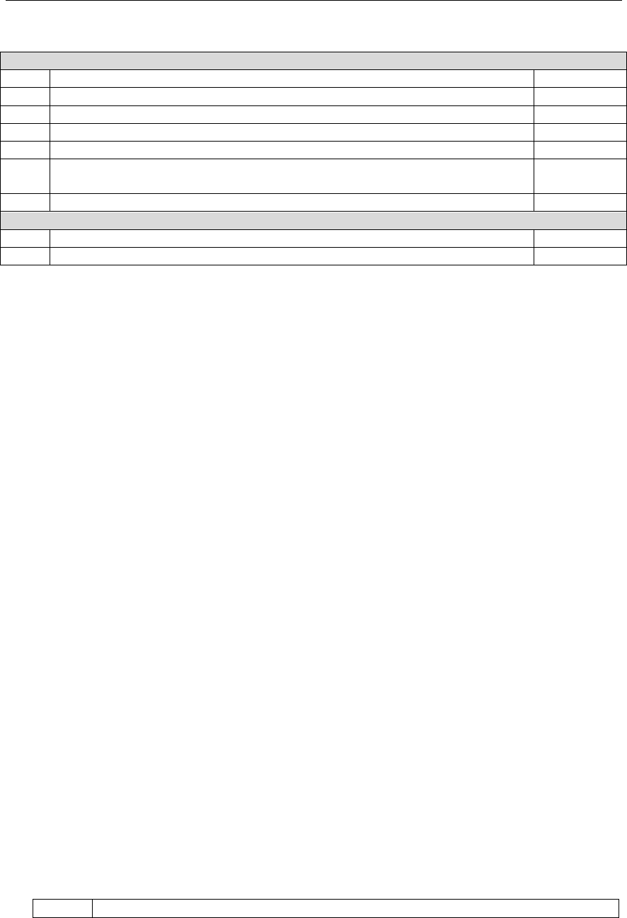
5.3 Sensor Array Set Up
(a)
(b)
Figure 1
No
Description
No
Description
1
Wind Vane (measures wind direction)
7
Solar panel
2
Wind Speed Sensor (measures wind speed)
8
U-Bolt
3
UV sensor/ Light sensor
9
Battery compartment
4
Thermometer-hygrometer sensor (measures
temperature and humidity)
10
Reset button
5
Rain collector
11
LED transmitter Indicator
6
Bubble level
Version 1.0 Page 5
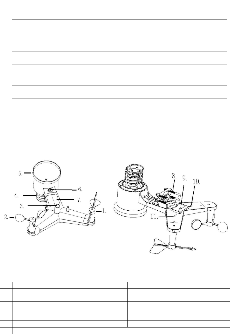
5.3.1 Install Wind Vane
Reference Figure 2. (a) Locate and align the flat key on the wind vane shaft to the flat key on the wind
vane and push the vane on to the shaft. (b) tighten the set screw with a precision screw driver and
make sure the wind vane spins freely.
(a)
(b)
Figure 2
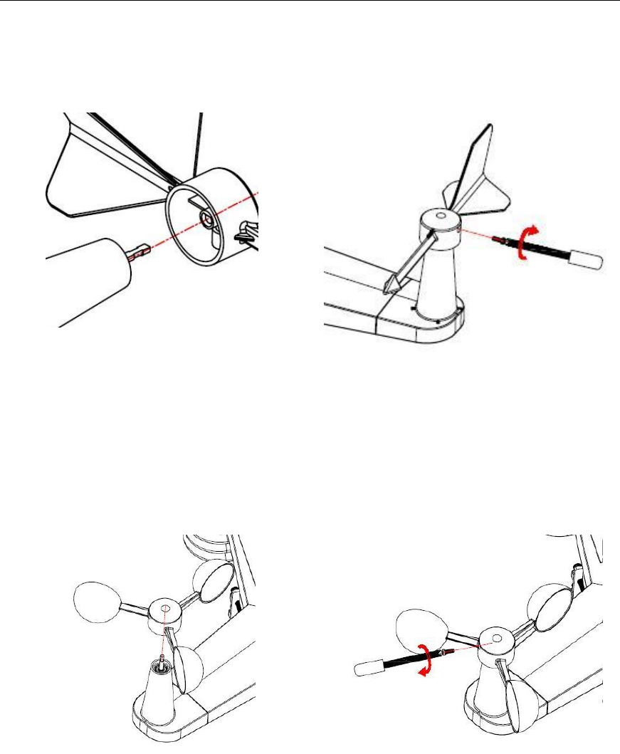
5.3.2 Install Wind Cups
Reference Figure 3. (a) push the wind cups on to the shaft. (b) tighten the set screw with a precision
screw driver and make sure the wind cups spin freely.
(a)
(b)
Figure 3
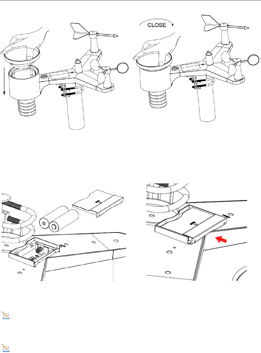
5.3.3 Install the Rain Gauge Funnel
Reference Figure 4. Install the rain gauge funnel. Rotate clockwise to attach the funnel to the sensor
array.
Version 1.0 Page 6
Figure 4
5.3.4 Install Batteries
Reference Figure 5. Insert 3 x AA non-rechargeable batteries (not included) into the battery
compartment. The LED indicator on the back of the transmitter will turn on for four seconds, and then
flash once every 16 seconds (the sensor transmission update period).
(a)
(b)
Figure 5
Note: If the LED does not light up, or stays on permanently, make sure the battery polarity is
correct, or the batteries are fresh. Do not install the batteries backwards. You can permanently damage
the thermo-hygrometer.
Note: We recommend lithium batteries for cold weather climates, but alkaline batteries are
sufficient for most climates. We do not recommend rechargeable batteries. They have lower voltages,
do not operate well at wide temperature ranges, and do not last as long, resulting in poorer reception.
Version 1.0 Page 7
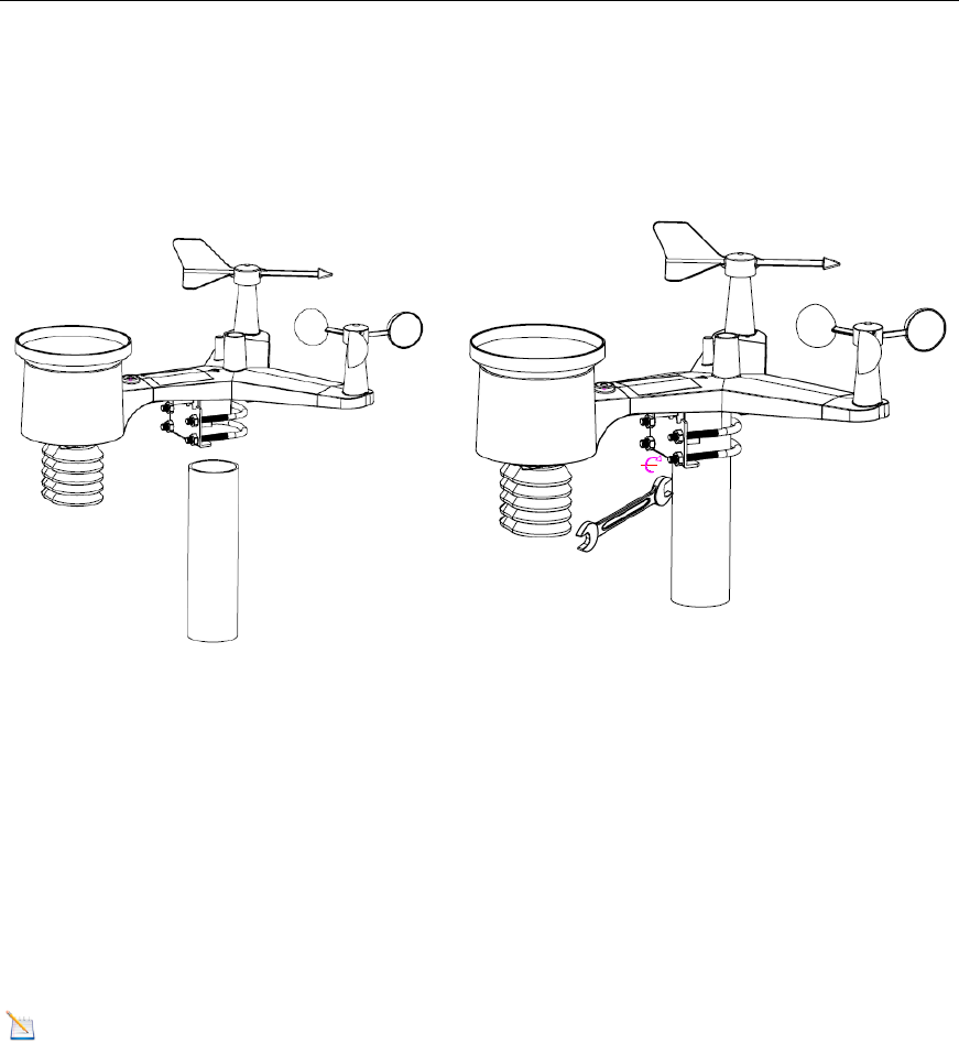
5.3.5 Install Mounting Pole
Reference Figure 6. The mounting assembly includes two U-Bolts and a bracket that tightens around
a 1 to 2” diameter pole (not included) using the four U-Bolt nuts.
(a)
(b)
Figure 6
Use the bubble level next to the rain sensor to make sure the sensor array is completely level. If the
sensor array is not level, the rain gauge will not measure properly.
5.3.5.1 Aligning the Wind Direction
Locate the four wind vane compass rose indicators of N, E, S, W (representing North, East, South and
West) at the base of the wind vane. Align the compass rose direction upon final installation with a
compass or GPS.
5.5 Best Practices for Wireless Communication
Note: To insure proper communication, mount the remote sensor(s) upright on a vertical surface,
such as a wall. Do not lay the sensor flat.
Wireless communication is susceptible to interference, distance, walls and metal barriers. We
recommend the following best practices for trouble free wireless communication.
1. Electro-Magnetic Interference (EMI). Keep the console several feet away from computer
monitors and TVs.
2. Radio Frequency Interference (RFI). If you have other 915 MHz devices and
communication is intermittent, try turning off these other devices for troubleshooting
purposes. You may need to relocate the transmitters or receivers to avoid intermittent
communication.
3. Line of Sight Rating. This device is rated at 300 feet line of sight (no interference, barriers or
walls) but typically you will get 100 feet maximum under most real-world installations, which
include passing through barriers or walls.
4. Metal Barriers. Radio frequency will not pass through metal barriers such as aluminum
siding. If you have metal siding, align the remote and console through a window to get a clear
line of sight.
Version 1.0 Page 8
The following is a table of reception loss vs. the transmission medium. Each “wall” or obstruction
decreases the transmission range by the factor shown below.
Medium
RF Signal Strength Reduction
Glass (untreated)
5-15%
Plastics
10-15%
Wood
10-40%
Brick
10-40%
Concrete
40-80%
Metal
90-100%
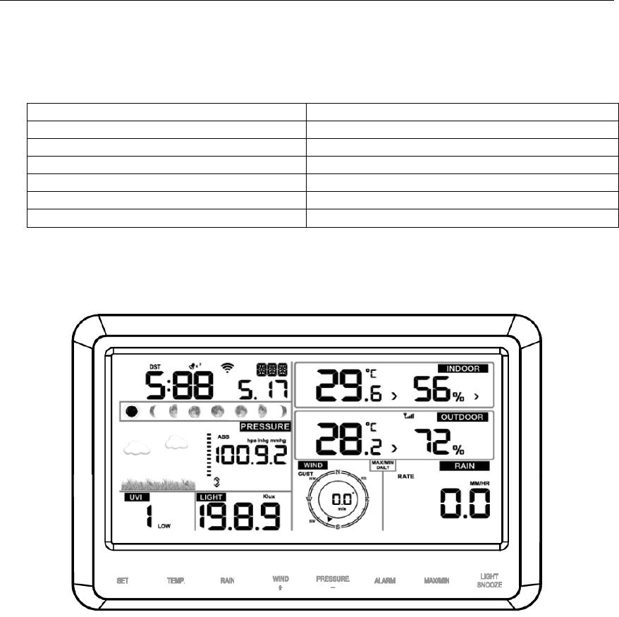
5.6 Display Console
The front and back of the display console is shown in Figure 7 and Figure 8.
Figure 7
Version 1.0 Page 9
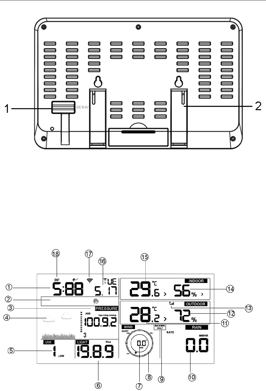
Figure 8
Reference Figure 8 (1). Connect the display console power jack to AC power with the power adapter
(included), (2) unfold the desk stand, and place 5 to 10 feet from the sensor array, and wait several
minutes for the remote sensors to synchronize with the display console.
6. Display Console Operation
6.1 Screen Display
The display console home screen layout is shown in Figure 9.
Figure 9
Version 1.0 Page 10
No
Description
No
Description
1
Time
10
Rainfall
2
Moon phase
11
Outdoor temperature
3
Barometric Pressure
12
Outdoor humidity
4
Weather forecast
13
RF icon
5
UV index
14
Indoor humidity
6
Solar Radiation
15
Indoor temperature
7
Wind speed
16
Date
8
Wind direction
17
WIFI icon
9
MAX/MIN Daily
18
DST
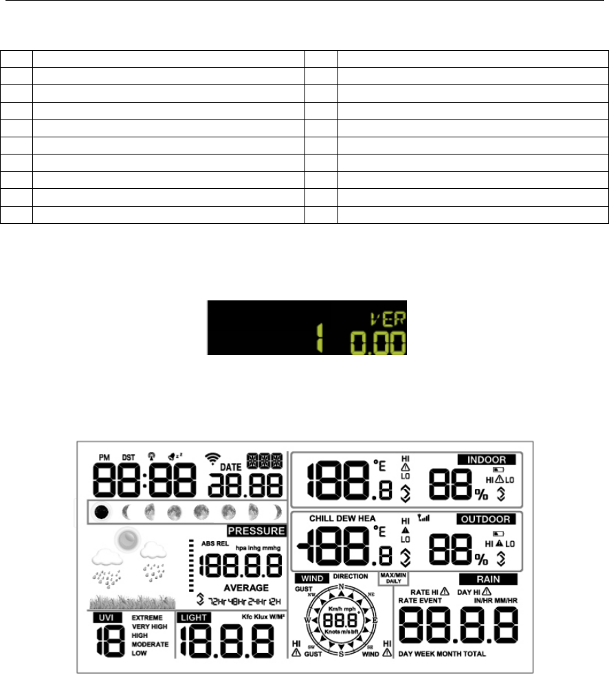
6.2 Console Initialization
After the console is connected to AC power, the console will display the software version number two
seconds after power up.
Figure 10
The console will display all of the LCD segments for three seconds after power up as shown in Figure
11, the indoor conditions will immediately update, and the outdoor sensor array will register within a
few minutes.
Figure 11
Version 1.0 Page 11
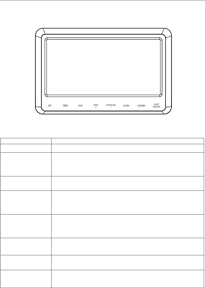
6.2.1 Button Operation
Figure 12
The console has 8 buttons at the bottom for easy operation:
Key
Description
SET
Press and hold to enter the SET mode.
TEMP.
Press to switch between Outdoor Temperature, Wind Chill, Heat
Index, Dew Point.
To bypass RF reception, press and hold while powering up the
console (connecting the AC adapter with batteries removed).
RAIN
Press to switch between Rain Rate (in/hr), Rain Event, Rain Day, Rain
Week, Rain Month, and Rain Total.
WIND +
Press to switch between average wind speed, wind gust and wind
direction.
While in SET mode, press to increase the value. Press and hold
for two seconds to increase the value rapidly.
PRESSURE -
Press to switch between Relative Pressure (current), and 12hr,
24hr, 48hr and 72hr average Relative Pressure.
While in SET mode, press to decrease the value. Press and hold
for two seconds to decrease the value rapidly.
ALARM
Press to switch between high and low alarms
MAX/MIN
Press to switch between minimum and maximum values.
LIGHT/SNOOZE
Press to adjust the LCD backlight brightness (high, medium and
off).
Press to exit the SET mode at any time.
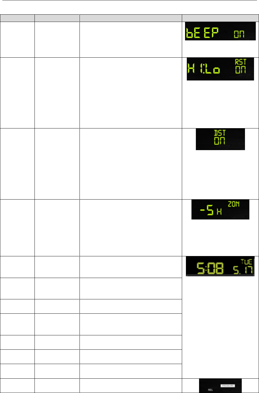
6.3 Set Mode
Press and hold the SET button for two seconds to enter the SET Mode. To proceed to the next setting,

Version 1.0 Page 13
Command
Mode
Settings
Image
[SET] + 2
seconds
Enter Set
Mode, Beep
On or Off
Press [WIND +] to switch OFF and
ON.
This will prevent the beep from
sounding when pressing any button.
[SET]
Clear Max/Min
Press [WIND +] to switch OFF and
ON.
When set to ON, the minimum and
maximum values reset every day at
midnight (00:00).
When set to OFF, the minimum and
maximum values must be reset
manually.
[SET]
Daylight
Savings Time
(DST)
Press [WIND +] to switch DST OFF
and ON.
Set to ON (most locations) if you
observe daylight savings time, and the
clock will automatically adjust twice
per year.
Set to OFF (Arizona and Hawaii) if
you do not observe DST.
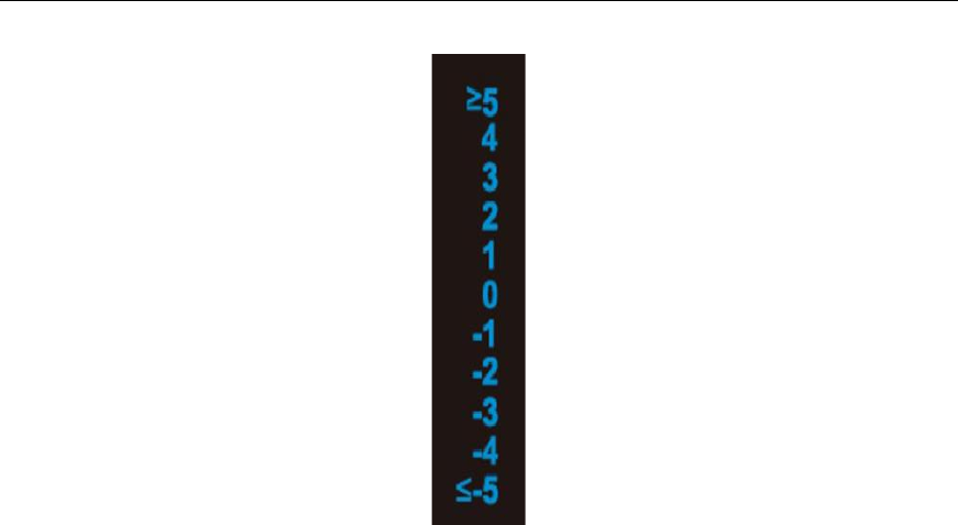
[SET]
Time Zone
Press [WIND +] or [PRESSURE -] to
adjust up or down (-12 to 12).
The default time zone is -5 (EST).
To find your time zone settings, please
reference Figure 14.
[SET]
12 hour / 24
Hour Format
Press [WIND +] to switch hour format
between 12 hour and 24 hour format.
[SET]
Hour
Press [WIND +] or [PRESSURE -] to
adjust hour up or down.
[SET]
Minute
Press [WIND +] or [PRESSURE -] to
adjust minute up or down.
[SET]
Date Format
Press [WIND +] to switch between
MM-DD (month-day) and DD-MM
(day-month)
[SET]
Year
Press [WIND +] or [PRESSURE -] to
adjust year up or down
[SET]
Month
Press [WIND +] or [PRESSURE -] to
adjust month up or down
[SET]
Day
Press [WIND +] or [PRESSURE -] to
adjust day up or down
[SET]
Pressure Units
of Measure
Press [WIND +] to change units of
measure between hpa, mmHg or inHg.
Version 1.0 Page 14
[SET]
Relative
Pressure
Calibration
Press [WIND +] or [PRESSURE -] to
adjust relative pressure up or down
Reference Section 6.4.4 for details on
calibration of relative pressure.
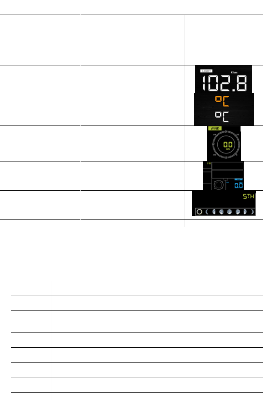
[SET]
Light Units of
Measure
Press [WIND +] to change light units
of measure between lux, fc, or w/m2
[SET]
Temperature
Units of
Measure
Press [WIND +] to change
temperature units of measure
between °F and °C.
[SET]
Wind Units of
Measure
Press [WIND +] to change wind units
of measure between km/h, mph, knots,
m/s and bft.
[SET]
Rain Units of
Measure
Press [WIND +] to change rain units
of measure between in and mm.
[SET]
Hemisphere
Press [WIND +] to change hemisphere
between NTH (northern) and STH
(southern). This setting effects the
moon phase display.
[SET]
Exit Set Mode
[SET] + 2 seconds means press and hold the SET button for two seconds.
[SET] means press the SET button.
Figure 13
6.3.1 Time Zones
The following table summarizes time zones around the world.
Hours from
GMT
Time Zone
Cities
-12
IDLW: International Date Line West
---
-11
NT: Nome
Nome, AK
-10
AHST: Alaska-Hawaii Standard
CAT: Central Alaska
HST: Hawaii Standard
Honolulu, HI
-9
YST: Yukon Standard
Yukon Territory
-8
PST: Pacific Standard
Los Angeles, CA, USA
-7
MST: Mountain Standard
Denver, CO, USA
-6
CST: Central Standard
Chicago, IL, USA
-5
EST: Eastern Standard
New York, NY, USA
-4
AST: Atlantic Standard
Caracas
-3
---
São Paulo, Brazil
-2
AT: Azores
Azores, Cape Verde Islands
-1
WAT: West Africa
---

Version 1.0 Page 15
Hours from
GMT
Time Zone
Cities
0
GMT: Greenwich Mean
WET: Western European
London, England
1
CET: Central European
Paris, France
2
EET: Eastern European
Athens, Greece
3
BT: Baghdad
Moscow, Russia
4
---
Abu Dhabi, UAE
5
---
Tashkent
6
---
Astana
7
---
Bangkok
8
CCT: China Coast
Bejing
9
JST: Japan Standard
Tokyo
10
GST: Guam Standard
Sydney
11
---
Magadan
12
IDLE: International Date Line East
NZST: New Zealand Standard
Wellington, New Zealand
Figure 14
6.4 Barometric Pressure Display
6.4.1 Viewing Absolute vs. Relative Pressure
To switch between absolute and relative pressure, press and hold the [PRESSURE -] button for two
seconds.
Absolute pressure is the measured atmospheric pressure, and is a function of altitude, and to a lesser
extent, changes in weather conditions.
Absolute pressure is not corrected to sea-level conditions.
Relative pressure is corrected to sea-level conditions. For further discussion of relative pressure and
calibration, reference Section 6.4.4.
6.4.2 Rate of Change of Pressure Graph
The rate of change of pressure graphic is shown to the left of the barometric pressure and signifies the
difference between the daily average pressure and the 30 day average (in hPa).
Version 1.0 Page 16
Figure 15
6.4.3 Viewing Pressure History
Press the [PRESSURE -] button to view the 12 hour, 24 hour, 48 hour and 72 hour pressure average.
6.4.4 Relative Pressure Calibration Discussion
To compare pressure conditions from one location to another, meteorologists correct pressure to
sea-level conditions. Because the air pressure decreases as you rise in altitude, the sea-level corrected
pressure (the pressure your location would be at if located at sea-level) is generally higher than your
measured pressure.
Thus, your absolute pressure may read 28.62 inHg (969 mb) at an altitude of 1000 feet (305 m), but
the relative pressure is 30.00 inHg (1016 mb).
The standard sea-level pressure is 29.92 in Hg (1013 mb). This is the average sea-level pressure
around the world. Relative pressure measurements greater than 29.92 inHg (1013 mb) are
considered high pressure and relative pressure measurements less than 29.92 inHg are considered low
pressure.
To determine the relative pressure for your location, locate an official reporting station near you (the
internet is the best source for real time barometer conditions, such as Weather.com or
Wunderground.com), and set your weather station to match the official reporting station.
6.5 Rain Display
6.5.1 Rain Increments of Measure
Press the RAIN button to switch between Rain Rate (in/hr), Rain Event, Rain Day, Rain Week, Rain
Month, and Rain Total.
6.5.2 Resetting Rain
To reset the rain totals, press and hold the RAIN button for two seconds.
Resetting the weekly rain also resets the daily rain.
Resetting the monthly rain also resets the daily and weekly rain.
Version 1.0 Page 17
Resetting the total rain also resets the monthly, weekly and daily rain.
6.5.3 Increments of Rain Definitions
Rain rate is defined as the last 10 minutes of rainfall, multiplied by six (10 minutes x 6 = 1
hour). This is also referred to as instantaneous rain per hour.
Rain event is defined as continuous rain, and resets to zero if rainfall accumulation is less
than 10 mm (0.039 in) in a 24 hour period.
Daily Rain is defined as the rainfall since midnight (00:00).
Weekly Rain is defined as the calendar week total, and resets on Sunday morning at midnight
(Sunday thru Saturday).
Monthly Rain is defined as the calendar month total, and resets on the first day of the Month.
Total Rain is defined as the running total since station was powered up.
6.6 Wind Display
Press the [WIND +] button to switch between average wind speed, wind gust and wind direction.
Wind speed is defined as the average wind speed in the 16 second update period.
Wind gust is defined as the peak wind speed in the 16 second update period.
6.7 Temperature Display
If temperature is lower than minimum range, the temperature field will display dashes (--.-).
If temperature is higher than maximum range, the temperature field will display dashes (--.-).
6.7.1 Wind Chill, Dew Point and Heat Index Display
Press the [TEMP] button to switch between Outdoor Temperature, Wind Chill, Heat Index, Dew
Point.
6.8 Alarms
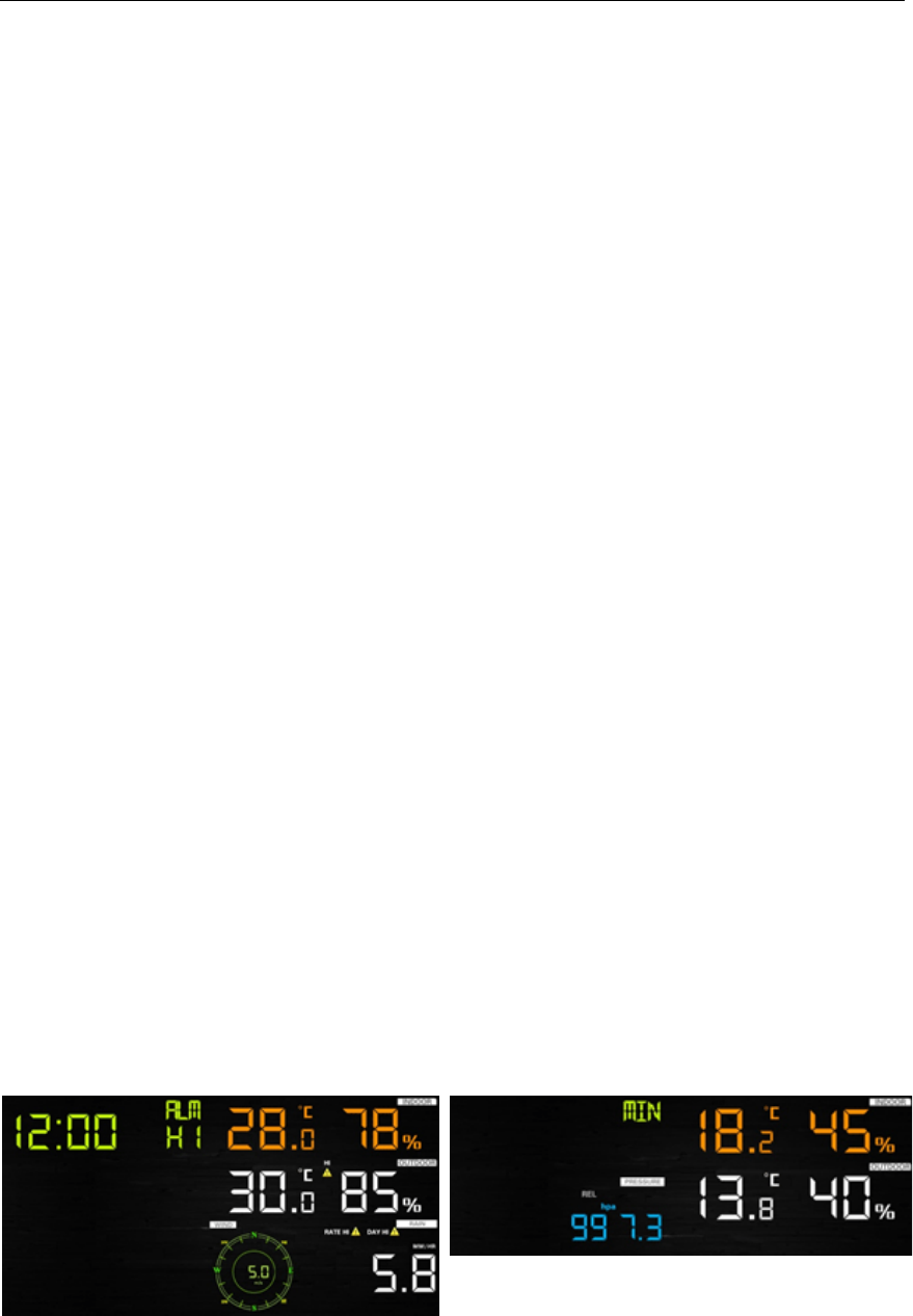
6.8.1 Viewing High and Low Alarms
To view the high alarm settings, press (do not hold) the ALARM button, and the high alarms will be
displayed, as shown in Figure 16 (a).
To view the low alarm settings, press the ALARM button again, and the low alarms will be displayed,
as shown in Figure 16 (b).
To return to normal mode, press the ALARM button again.
(a)
(b)
Figure 16

Version 1.0 Page 18
6.8.1.1 Rain Alarm
While the High Alarm is displayed (reference Section 6.8.1), press the RAIN button to display the rain
rate and daily rain alarm values.
6.8.1.2 Wind Alarm
While the High Alarm is displayed (reference Section 6.8.1), press the WIND button to display the
wind speed and wind gust alarm values.
6.8.2 Setting High and Low Alarms
Press and hold the ALARM button for two seconds to enter the ALARM Set Mode. To save and
proceed to the next alarm setting, press (do not hold) the SET button.
To exit the alarm mode at any time, press the LIGHT / SNOOZE button.
Figure 17Figure 13 summarizes the alarm mode sequence and commands.
Version 1.0 Page 19
Command
Mode
Settings
[ALARM]
+ 2
seconds
Enter Alarm Set Mode, Alarm
Hour
Press [WIND +] or [PRESSURE -] to adjust alarm
hour up or down.
Press [ALARM] to turn the time alarm on or off.
When the alarm is on, the alarm time icon
will appear.
[SET]
Alarm Minute
Press [WIND +] or [PRESSURE -] to adjust alarm
minute up or down.
Press [ALARM] to turn the time alarm on. The
alarm time icon will appear.
Press [ALARM] again to turn the time alarm off.
The alarm time icon will disappear.
[SET]
Alarm High Indoor Temperature
Press [WIND +] or [PRESSURE -] to adjust alarm
value up or down.
Press [ALARM] to turn the alarm on. The alarm
icon will appear.
Press [ALARM] to turn the alarm off. The alarm
icon will disappear.
[SET]
Alarm Low Indoor Temperature
Press [WIND +] or [PRESSURE -] to adjust alarm
value up or down.
Press [ALARM] to turn the alarm on. The alarm
icon will appear.
Press [ALARM] to turn the alarm off. The alarm
icon will disappear.
[SET]
Alarm High Indoor Humidity
Press [WIND +] or [PRESSURE -] to adjust alarm
value up or down.
Press [ALARM] to turn the alarm on. The alarm
icon will appear.
Press [ALARM] to turn the alarm off. The alarm
icon will disappear.
Version 1.0 Page 20
[SET]
Alarm Low Indoor Humidity
Press [WIND +] or [PRESSURE -] to adjust alarm
value up or down.
Press [ALARM] to turn the alarm on. The alarm
icon will appear.
Press [ALARM] to turn the alarm off. The alarm
icon will disappear.
[SET]
Alarm High Outdoor
Temperature
Press [WIND +] or [PRESSURE -] to adjust alarm
value up or down.
Press [ALARM] to turn the alarm on. The alarm
icon will appear.
Press [ALARM] to turn the alarm off. The alarm
icon will disappear.
[SET]
Alarm Low Outdoor Temperature
Press [WIND +] or [PRESSURE -] to adjust alarm
value up or down.
Press [ALARM] to turn the alarm on. The alarm
icon will appear.
Press [ALARM] to turn the alarm off. The alarm
icon will disappear.
[SET]
Alarm High Outdoor Humidity
Press [WIND +] or [PRESSURE -] to adjust alarm
value up or down.
Press [ALARM] to turn the alarm on. The alarm
icon will appear.
Press [ALARM] to turn the alarm off. The alarm
icon will disappear.
[SET]
Alarm Low Outdoor Humidity
Press [WIND +] or [PRESSURE -] to adjust alarm
value up or down.
Press [ALARM] to turn the alarm on. The alarm
icon will appear.
Press [ALARM] to turn the alarm off. The alarm
icon will disappear.
Version 1.0 Page 21
[SET]
Alarm High Wind Speed
Press [WIND +] or [PRESSURE -] to adjust alarm
value up or down.
Press [ALARM] to turn the alarm on. The alarm
icon will appear.
Press [ALARM] to turn the alarm off. The alarm
icon will disappear.
[SET]
Alarm High Wind Gust
Press [WIND +] or [PRESSURE -] to adjust alarm
value up or down.
Press [ALARM] to turn the alarm on. The alarm
icon will appear.
Press [ALARM] to turn the alarm off. The alarm
icon will disappear.
[SET]
Alarm High Rain Rate
Press [WIND +] or [PRESSURE -] to adjust alarm
value up or down.
Press [ALARM] to turn the alarm on. The alarm
icon will appear.
Press [ALARM] to turn the alarm off. The alarm
icon will disappear.
[SET]
Alarm High Daily Rain
Press [WIND +] or [PRESSURE -] to adjust alarm
value up or down.
Press [ALARM] to turn the alarm on. The alarm
icon will appear.
Press [ALARM] to turn the alarm off. The alarm
icon will disappear.
[SET]
Exit alarm settings mode.
[ALARM] + 2 seconds means press and hold the ALARM button for two seconds.
[ALARM] means press the ALARM button.
Figure 17
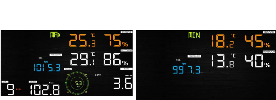
6.9 Max/Min Mode
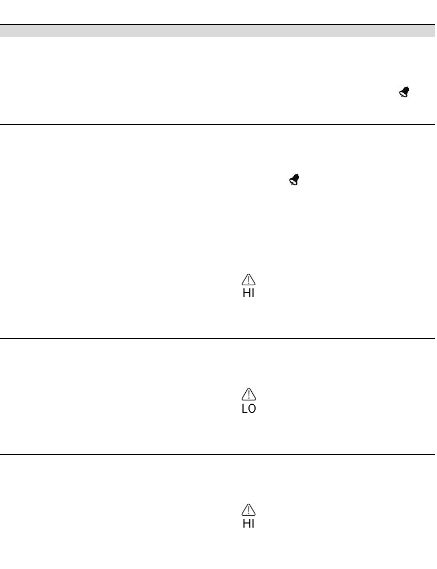
6.9.1 Viewing Max/Min Values
To view the max value, press (do not hold) the MAX/MIN button, and the max values will be
displayed, as shown in Figure 18 (a).
To view the low alarm settings, press the MAX/MIN button again, and the min values will be
displayed, as shown in Figure 18 (b).
Version 1.0 Page 22
To return to normal mode, press the ALARM button again.
(a)
(b)
Figure 18
6.9.1.1 Display Wind Chill, Heat Index vs. Dew Point Max/Min Values
While the max values are displayed as outlined in Section 6.9.1, press the TEMP button once to view
the heat index, twice to view the dew point, and a third time to return to outdoor temperature.
While the min values are displayed as outlined in Section 6.9.1, press the TEMP button once to view
the wind chill, twice to view the dew point, and a third time to return to outdoor temperature.
6.9.1.2 Display Wind Speed vs. Wind Gust Max Values
While the max values are displayed as outlined in Section 6.9.1, press the WIND + button once to
view the max wind gust, and twice to return to wind speed.
6.9.1.3 Display Rain Rate, Daily Rain, Weekly Rain and Monthly Rain
Max Values
While the max values are displayed as outlined in Section 6.9.1, press the RAIN button once to view
the max daily rain, twice to view the max weekly rain, three times to view the max monthly rain, four
times to return to the max rain rate.
6.9.1.4 Display Absolute and Relative Pressure Min and Max Values
While the max values are displayed as outlined in Section 6.9.1, press and hold the PRESSURE
button for two seconds to view the absolute pressure, and press and hold the PRESSURE button for
two seconds again to return to relative pressure.
While the min values are displayed as outlined in Section 6.9.1, press and hold the PRESSURE
button for two seconds to view the absolute pressure, and press and hold the PRESSURE button for
two seconds again to return to relative pressure.
6.10 Calibration
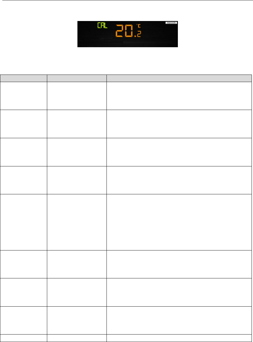
6.10.1 Calibration Settings
Press and hold the TEMP. and MAX/MIN buttons at the same time for 5 seconds to enter calibration
mode. The CAL icon will be displayed.
To save and proceed to the next calibration setting, press (do not hold) the SET button.
To exit the calibration mode at any time, press the LIGHT / SNOOZE button.
Version 1.0 Page 23
Figure 19
Figure 20 summarizes the set mode sequence and commands.
Command
Mode
Settings
TEMP. and
MAX/MIN
+ 5 seconds
Enter Calibration
Mode, Indoor
Temperature
Press [WIND +] or [PRESSURE -] to adjust the indoor
temperature up or down.
To restore to factory default, press [ALARM].
[SET]
Indoor Humidity
Press [WIND +] or [PRESSURE -] to adjust the indoor
humidity up or down.
To restore to factory default, press [ALARM].
[SET]
Outdoor Temperature
Press [WIND +] or [PRESSURE -] to adjust the outdoor
temperature up or down.
To restore to factory default, press [ALARM].
[SET]
Outdoor Humidity
Press [WIND +] or [PRESSURE -] to adjust the outdoor
humidity up or down.
To restore to factory default, press [ALARM].
[SET]
Absolute Pressure
Press [WIND +] or [PRESSURE -] to adjust the absolute
pressure up or down.
To restore to factory default, press [ALARM].
Note: The absolute pressure calibration affects the
relative pressure by the same amount. It is recommend
you calibrate the relative pressure only, per Section 6.3.
[SET]
Wind Direction
Press [WIND +] or [PRESSURE -] to adjust the wind
direction up or down.
To restore to factory default, press [ALARM].
[SET]
Wind Speed Factor
Press [WIND +] or [PRESSURE -] to adjust the wind
speed factor up or down.
To restore to factory default, press [ALARM].
[SET]
Rain Factor
Press [WIND +] or [PRESSURE -] to adjust the rain
factor up or down.
To restore to factory default, press [ALARM].
[SET]
Exit calibration mode
Figure 20
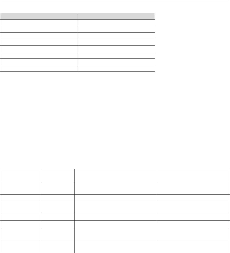
6.10.2 Calibration Ranges
The following table summarizes the permissible calibration ranges.
Version 1.0 Page 24
Parameter
Range
Indoor Temperature
± 9 °F
Indoor Humidity
± 9%
Outdoor Temperature
± 9 °F
Outdoor Humidity
± 9%
Absolute Pressure
± 10 hpa (± 2.95 inHg)
Wind Direction
± 180 °
Wind Speed Factor
0.5 to 1.5
Rain Factor
0.5 to 1.5
Figure 21
6.10.3 Calibration Discussion
The purpose of calibration is to fine tune or correct for any sensor error associated with the devices
margin of error. Errors can occur due to electronic variation (example, the temperature sensor is a
resistive thermal device or RTD, the humidity sensor is a capacitance device), mechanical variation, or
degradation (wearing of moving parts, contamination of sensors).
Calibration is only useful if you have a known calibrated source you can compare it against, and is
optional. This section discusses practices, procedures and sources for sensor calibration to reduce
manufacturing and degradation errors. Do not compare your readings obtained from sources such as
the internet, radio, television or newspapers. The purpose of your weather station is to measure
conditions of your surroundings, which vary significantly from location to location.
Parameter
Type of
Calibration
Default
Typical Calibration Source
Temperature
Offset
Current Value
Red Spirit or Mercury
Thermometer (1)
Humidity
Offset
Current Value
Sling Psychrometer (2)
ABS
Barometer
Offset
Current Value
Calibrated laboratory grade
barometer
REL Barometer
Offset
Current Value
Local airport (3)
Wind Direction
Offset
Current Value
GPS, Compass (4)
Wind
Gain
1.00
Calibrated laboratory grade
wind meter (5)
Rain
Gain
1.00
Sight glass rain gauge with an
aperture of at least 4” (6)
Figure 22
(1) Temperature errors can occur when a sensor is placed too close to a heat source (such as a
building structure, the ground or trees).
To calibrate temperature, we recommend a mercury or red spirit (fluid) thermometer. Bi-metal
(dial) and digital thermometers (from other weather stations) are not a good source and have
their own margin of error. Using a local weather station in your area is also a poor source due
to changes in location, timing (airport weather stations are only updated once per hour) and
possible calibration errors (many official weather stations are not properly installed and
calibrated).
Place the sensor in a shaded, controlled environment next to the fluid thermometer, and allow
the sensor to stabilize for 48 hours. Compare this temperature to the fluid thermometer and
adjust the console to match the fluid thermometer.

Version 1.0 Page 25
(2) Humidity is a difficult parameter to measure electronically and drifts over time due to
contamination. In addition, location has an adverse affect on humidity readings (installation
over dirt vs. lawn for example).
Official stations recalibrate or replace humidity sensors on a yearly basis. Due to
manufacturing tolerances, the humidity is accurate to ± 5%. To improve this accuracy, the
indoor and outdoor humidity can be calibrated using an accurate source, such as a sling
psychrometer.
(3) The display console displays two different pressures: absolute (measured) and relative
(corrected to sea-level).
To compare pressure conditions from one location to another, meteorologists correct pressure
to sea-level conditions. Because the air pressure decreases as you rise in altitude, the sea-level
corrected pressure (the pressure your location would be at if located at sea-level) is generally
higher than your measured pressure.
Thus, your absolute pressure may read 28.62 inHg (969 mb) at an altitude of 1000 feet (305
m), but the relative pressure is 30.00 inHg (1016 mb).
The standard sea-level pressure is 29.92 in Hg (1013 mb). This is the average sea-level
pressure around the world. Relative pressure measurements greater than 29.92 inHg (1013
mb) are considered high pressure and relative pressure measurements less than 29.92 inHg are
considered low pressure.
To determine the relative pressure for your location, locate an official reporting station near
you (the internet is the best source for real time barometer conditions, such as Weather.com or
Wunderground.com), and set your weather station to match the official reporting station.
(4) Only use this if you improperly installed the weather station sensor array, and did not point
the direction reference to true north.
(5) Wind speed is the most sensitive to installation constraints. The rule of thumb for properly
installing a wind speed sensor is 4 x the distance of the tallest obstruction. For example, if
your house is 20’ tall and you mount the sensor on a 5’ pole:
Distance = 4 x (20 – 5)’ = 60’.
Many installations are not perfect and installing the weather station on a roof can be difficult.
Thus, you can calibrate for this error with a wind speed multiplier.
In addition to the installation challenges, wind cup bearings (moving parts) wear over time.
Without a calibrated source, wind speed can be difficult to measure. We recommend using a
calibrated wind meter and a constant speed, high speed fan.
(6) The rain collector is calibrated at the factory based on the funnel diameter. The bucket tips
every 0.01” of rain (referred to as resolution). The accumulated rainfall can be compared to a
sight glass rain gauge with an aperture of at least 4”.
Make sure you periodically clean the rain gauge funnel.
Version 1.0 Page 26
6.11 Restoring the Console to Factory Default
To restore the console to factory default, perform the following steps:
1. Remove the power from the console by removing the batteries and disconnecting the AC
adapter.
2. Apply power by connecting the AC adapter.
3. Wait for all of the segments to appear on the screen, as shown in Figure 11.
4. Press and hold the WIND/+ and PRESSURE/- buttons at the same time until the console
power up sequence is complete (about 5 seconds).
5. Replace the batteries.
6.12 Resynchronize Wireless Sensor
Press and hold the LIGHT /SNOOZE button for 5 seconds, and the console will re-register the
wireless sensor.
6.13 Backlight Operation
6.13.1 With AC Adapter
The backlight can only be continuously on when the AC adapter is permanently on. When the AC
adapter is disconnected, the backlight can be temporarily turned on.
Press the LIGHT SNOOZE button to adjust the brightness between High, Low and Off.
6.13.2 Without AC Adapter
To reduce power consumption, the console will sleep on battery power only, and will not send data to
the Internet.
To temporarily turn on the back light for 15 seconds, press the LIGHT SNOOZE button.
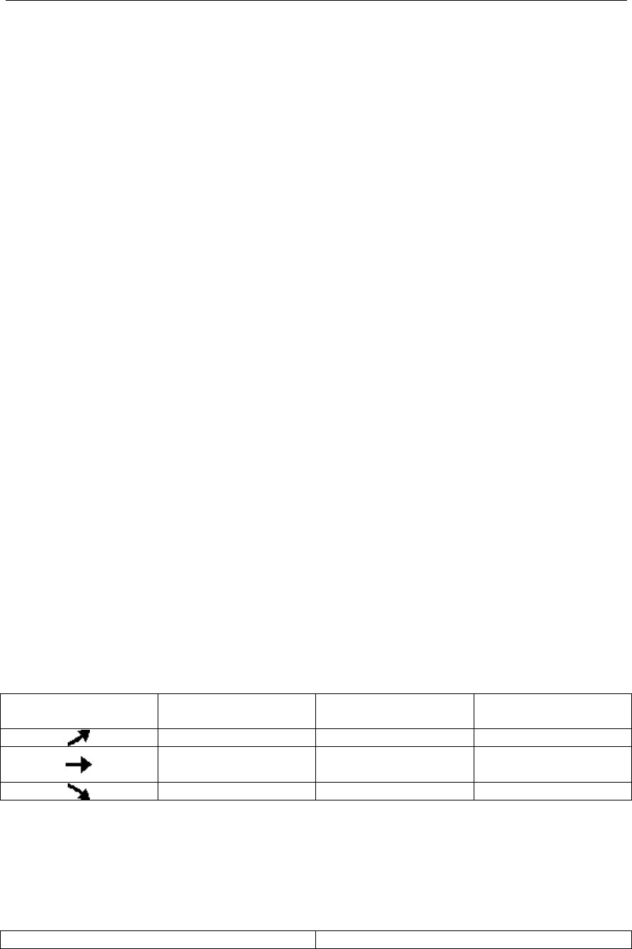
6.14 Tendency Arrows
Tendency arrows allow you to quickly determine of temperature or pressure are rising and falling in a
three hour update period, updated every 30 minutes.
Figure 23 defines the conditions for rising and falling pressure every 3 hours.
Tendency indicators
Condition
Humidity Change per
3 Hours
Temperature Change
per 3 Hours
Rising
Rising > 3%
Rising > 1º C / 2 ºF
Steady
Change ≤ ±3%
Change ≤ ± 1 º C /
2 º F
Falling
Falling > 3%
Falling > 1º C / 2 ºF
Figure 23
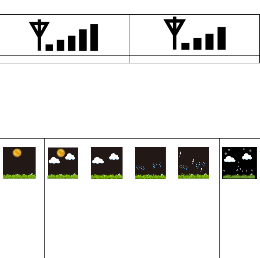
6.15 Wireless Signal Strength Indicator
The wireless signal strength displays reception quality. If no signal is lost, the signal strength indicator
will display 5 bars. If the signal is lost once, four bars will be displayed, a shown in Figure 24.
Five Bars
Four Bars
Version 1.0 Page 27
No signal loss
Lost signal once
Figure 24
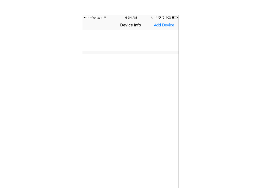
6.16 Weather Forecasting
The five weather icons are Sunny, Partly Cloudy, Cloudy, Rainy and Stormy.
The forecast icon is based on the rate of change of barometric pressure. Please allow at least one month
for the weather station to learn the barometric pressure over time.
Sunny
Partly Cloudy
Cloudy
Rainy
Stormy
Snowy
Pressure
increses for a
sustained
period of time
Pressure
increases
slightly, or
initial power
up
Pressure
decreases
slightly
Pressure
decreases for a
sustained
period of time
Pressure
rapidly
decreases
Pressure
decreases for
a sustained
period of
time and
temperature
is below
freezing
Figure 25
6.16.1 Weather Forecasting Description and Limitations
In general, if the rate of change of pressure increases, the weather is generally improving (sunny to
partly cloudy). If the rate of change of pressure decreases, the weather is generally degrading (cloudy,
rainy or stormy). If the rate of change is relatively steady, it will read partly cloudy.
The reason the current conditions do not match the forecast icon is because the forecast is a prediction
24-48 hours in advance. In most locations, this prediction is only 70% accurate and it is a good idea to
consult the National Weather Service for more accurate weather forecasts. In some locations, this
prediction may be less or more accurate. However, it is still an interesting educational tool for learning
why the weather changes.
The National Weather Service (and other weather services such as Accuweather and The Weather
Channel) have many tools at their disposal to predict weather conditions, including weather radar,
weather models, and detailed mapping of ground conditions.

Version 1.0 Page 28
7. Live Internet Publishing
The WS-2902 sends data to three free hosting services:
Hosting Service
Website
Description
Weather Undergound
WeatherUndeground.com
Weather Underground is a free weather
hosting service that allows you to send and
view your weather station data real-time, view
graphs and gauges, import text data for more
detailed analysis and use iPhone, iPad and
Android applications available at
Wunderground.com. Weather Underground is
a subsidiary of The Weather Channel and
IBM.
WeatherBug
Community
backyard.weatherbug.com
WeatherBug Community is an extension of
the WeatherBug community of weather
stations. WeatherBug is a brand owned by
Earth Networks that provides live weather
data and maintains a mesoscale network of
over 8,000 weather stations.
Weather Cloud
WeatherCloud.net
Weathercloud is a real-time weather social
network formed by observers from around the
world.
The WS-2902 weather station sends data to the Internet using your WiFi connection.
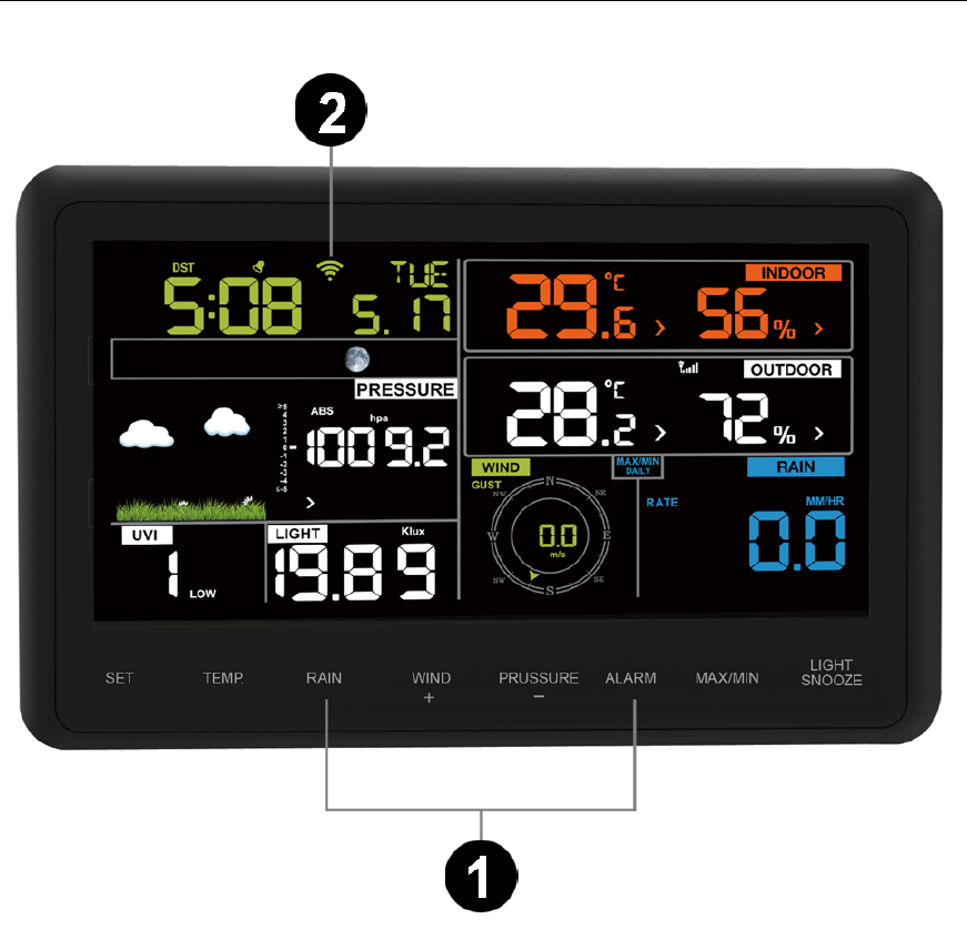
7.1 Connecting the Weather Station Console to WiFi
The WiFi feature only works when plugged into AC power due to higher energy requirements.
To connect the weather station to WiFi, you must first download the application from one of the
following choices:
Apple App Store
Google Play Store
1. From your mobile device, visit the Apple App Store or Google Play Store and search for the
“WS Tool” application. Download this application to your mobile device.
2. Run the application, and select Add Device, as shown in Figure 26.
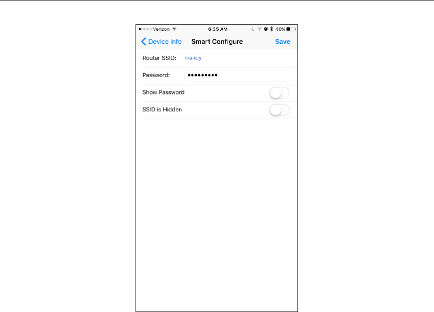
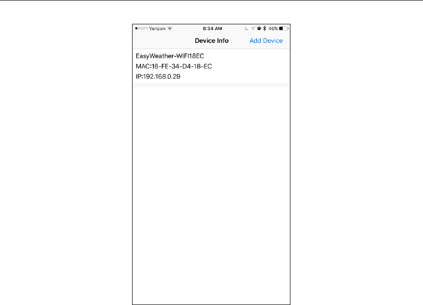
Version 1.0 Page 33
Figure 30
8. Registering with WeatherUnderground.com,
WeatherBug.com and WeatherCloud.net
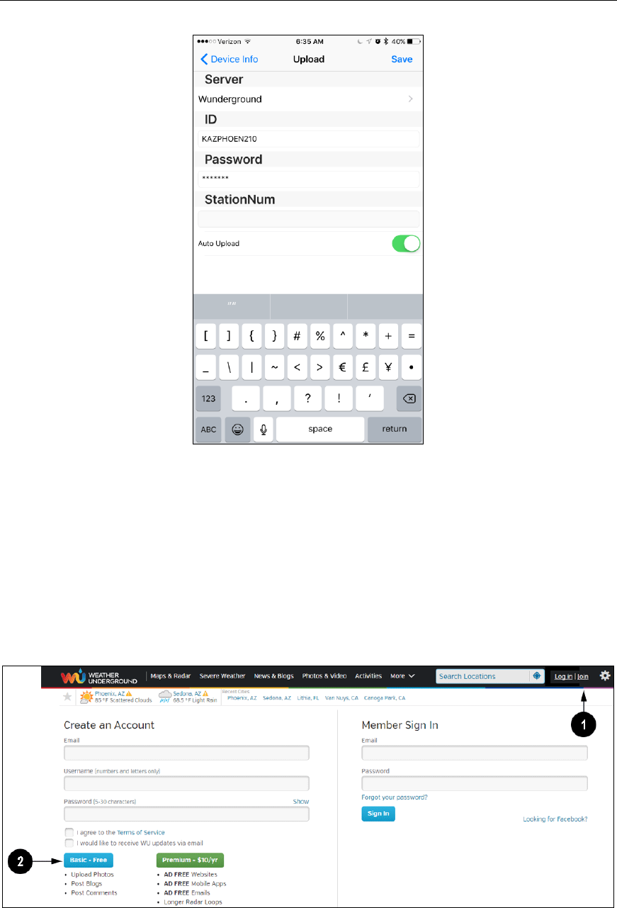
8.1 WeatherUnderground.com
Visit Wunderground.com and select the Join link at the top of the page. Select the Free sign up option.
Figure 31
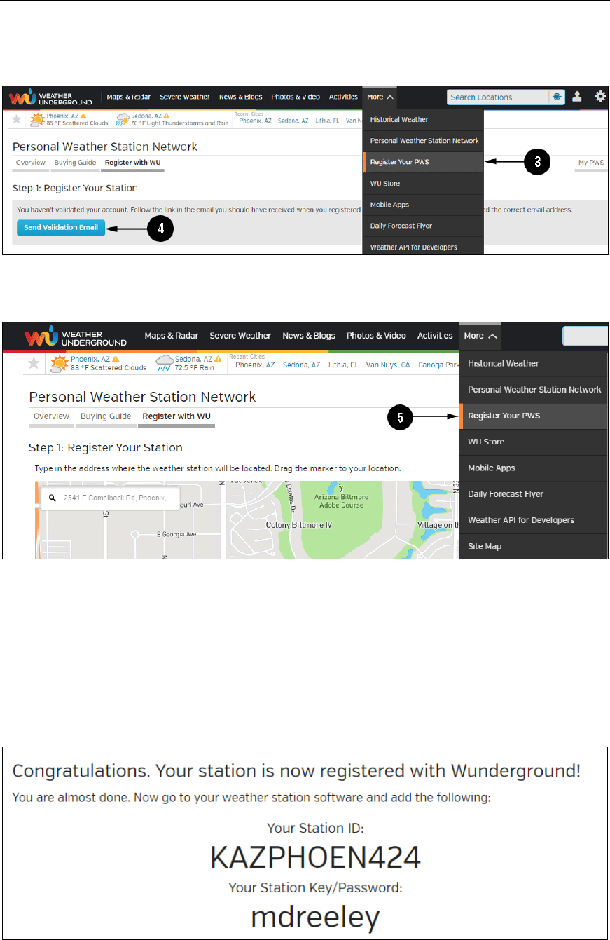
1. Select More | Register Your PWS.
Version 1.0 Page 34
2. Click Send Validation Email. Respond to the validation email from Wunderground (it may
take a few minutes).
Figure 32
3. Select More | Register Your PWS again and enter all of the information requested.
Figure 33
4. After registering your station, make a note of the following:
Station ID
Station Key / Password
Enter the Station ID (ID), Station Key (Password) and Station Number (StationNum) into the Tool.
Leave the StationNum field blank.
Figure 34 is an example, and your station ID and password will be different.
Version 1.0 Page 35
Figure 34
Note: Your station ID will have the form: KSSCCCC###, where K is for USA station (I for
international), SS is your state, CCCC is your city and ### is the station number in that city.
In the example above, KAZPHOEN424 is in the USA (K), State of Arizona (AZ), City of Phoenix
(PHOEN) and #424.
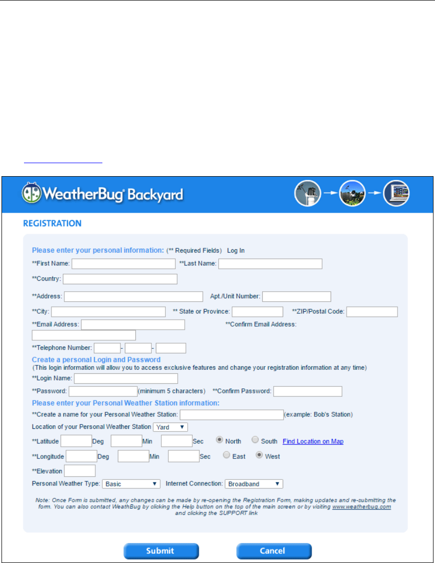
8.2 WeatherBug.com
Visit http://pws.ensb.us/ and Click here to register your station.
Figure 35
After registering your station, make a note of the following:
UserName
Password
Your Publisher ID
Your Station Number
Version 1.0 Page 36
Enter the Publisher ID (ID), Password and Station Number (StationNum) into the WS Tool.
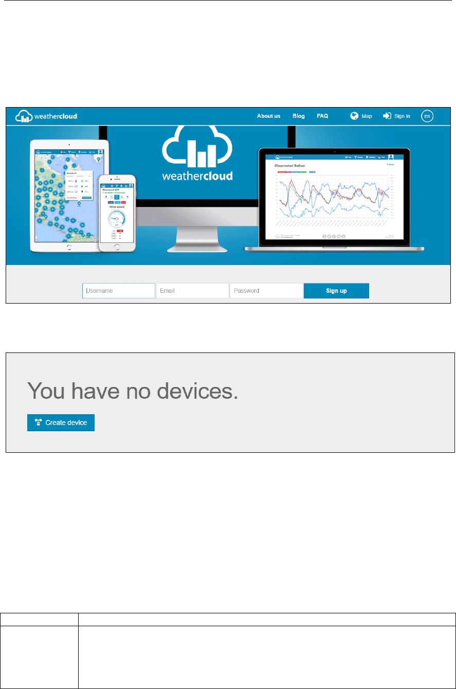
8.3 WeatherCloud
1. Visit WeatherCloud.net and enter a Username, Email and Password.
Figure 36
2. Respond to the validation email from WeatherCloud (it may take a few minutes).
Figure 37
3. Select Create Device and enter your weather station information. After registering your
station, make a note of the following:
Weathercloud ID
Key
Enter the Weathercloud ID (ID), Key (password) into the WS Tool. Leave the Station Number
(StationNum) blank.
9. Glossary of Terms
Term
Definition
Absolute
Barometric
Pressure
Absolute pressure is the measured atmospheric pressure and is a function of altitude,
and to a lesser extent, changes in weather conditions.
Absolute pressure is not corrected to sea-level conditions. Refer to Relative
Barometric Pressure.
Version 1.0 Page 37
Term
Definition
Accuracy
Accuracy is defined as the ability of a measurement to match the actual value of the
quantity being measured.
Barometer
A barometer is an instrument used to measure atmospheric pressure.
Calibration
Calibration is a comparison between measurements – one of known magnitude or
correctness of one device (standard) and another measurement made in as similar a
way as possible with a second device (instrument).
Dew Point
The dew point is the temperature at which a given parcel of humid air must be
cooled, at constant barometric pressure, for water vapor to condense into water. The
condensed water is called dew. The dew point is a saturation temperature.
The dew point is associated with relative humidity. A high relative humidity
indicates that the dew point is closer to the current air temperature. Relative
humidity of 100% indicates the dew point is equal to the current temperature and the
air is maximally saturated with water. When the dew point remains constant and
temperature increases, relative humidity will decrease.
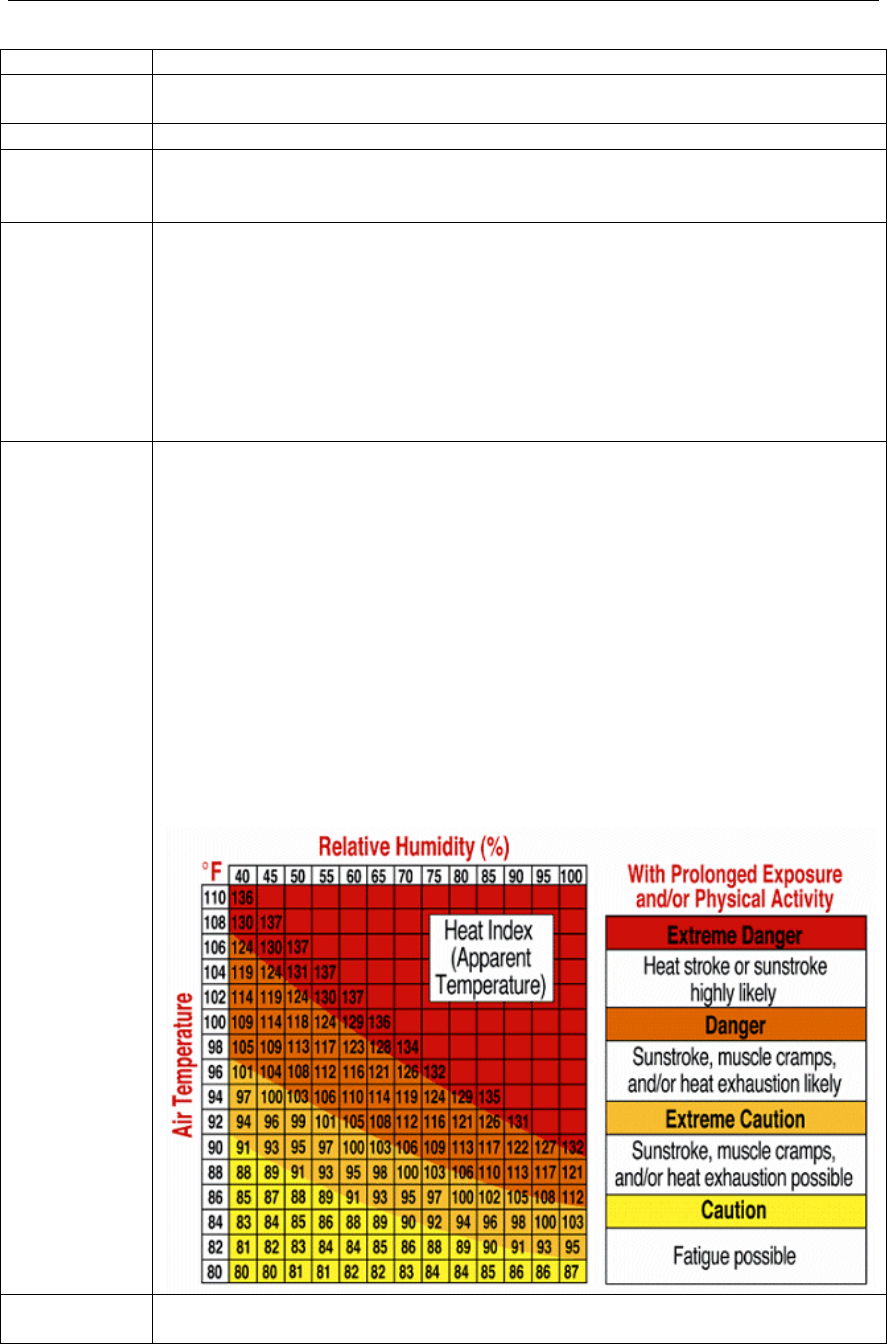
Heat Index
The Heat Index, sometimes referred to as the apparent temperature, is a measure of
how hot it really feels when relative humidity is factored with the actual air
temperature.
To find the Heat Index temperature, look at the Heat Index chart below. As an
example, if the air temperature is 96°F and the relative humidity is 65%, the heat
index (how hot it feels) is 121°F.
IMPORTANT: Since heat index values were devised for shady, light wind
conditions, exposure to full sunshine can increase heat index values by up to 15°F.
Also, strong winds, particularly with very hot, dry air, can be extremely hazardous.
The Heat Index Chart shaded zone above 105°F shows a level that may cause
increasingly severe heat disorders with continued exposure or physical activity.
Heat Index is not calculated below 80°F.
HectoPascals
(hPa)
Pressure units in SI (international system) units of measurement. Same as millibars
(1 hPa = 1 mbar)

Version 1.0 Page 38
Term
Definition
Hygrometer
A hygrometer is a device that measures relative humidity. Relative humidity is a
term used to describe the amount or percentage of water vapor that exists in air.
Inches of
Mercury
(inHg)
Pressure in Imperial units of measure.
1 inch of mercury = 33.86 millibars
Rain Gauge
A rain gauge is a device that measures liquid precipitation (rain), as opposed to solid
precipitation (snow gauge) over a set period of time.
All digital rain gauges are self emptying or self dumping (also referred to as tipping
rain gauge). The precision of the rain gauge is based on the volume of rain per
emptying cycle.
Range
Range is defined as the amount or extent a value can be measured.
Relative
Barometric
Pressure
Measured barometric pressure relative to your location or ambient conditions.
Resolution
Resolution is defined as the number of significant digits (decimal places) to which a
value is being reliably measured.
Solar
Radiation
A solar radiation sensor measures solar energy from the sun.
Solar radiation is radiant energy emitted by the sun from a nuclear fusion reaction
that creates electromagnetic energy. The spectrum of solar radiation is close to that
of a black body with a temperature of about 5800 K. About half of the radiation is in
the visible short-wave part of the electromagnetic spectrum. The other half is mostly
in the near-infrared part, with some in the ultraviolet part of the spectrum.
Thermometer
A thermometer is a device that measures temperature. Most digital thermometers are
resistive thermal devices (RTD). RTDs predict change in temperature as a function
of electrical resistance.
Wind Vane
A wind vane is a device that measures the direction of the wind. The wind vane is
usually combined with the anemometer. Wind direction is the direction from which
the wind is blowing.
10. Specifications
10.1 Wireless Specifications
Line of sight wireless transmission (in open air): 330 feet, 100 feet under most conditions
Update Rate: Outdoor Sensor: 16 seconds, Indoor Sensor: 64 seconds
Frequency: 915 MHz
Version 1.0 Page 39
10.2 Measurement Specifications
The following table provides the specifications for the measured parameters.
Measurement
Range
Accuracy
Resolution
Indoor Temperature
14 to 140 °F
± 2 °F
0.1 °F
Outdoor Temperature
-40 to 149 °F (lithium
batteries)
-23 to 140 °F (alkaline
batteries)
± 2 °F
0.1 °F
Indoor Humidity
10 to 99%
± 5%
1 %
Outdoor Humidity
10 to 99%
± 5%
1 %
Barometric Pressure
8.85 to 32.50 inHg
± 0.08 inHg (within range of
27.13 to 32.50 inHg)
0.01 inHg
Light
0 to 200,000 Lux
± 15%
1 Lux
Rain
0 to 394 in.
± 5%
0.01 in
Wind Direction
0 - 360 º
± 10º
1º
Wind Speed
0 to 100 mph (operational)
± 2.2 mph or 10% (whichever
is greater)
1.4 mph
10.3 Power Consumption
Base station : 5V DC Adaptor (included), Power Consumption: 0.5 Watts (1.25 Watts during
WiFi configuration mode)
Outdoor sensor array: 3xAA batteries (not included)
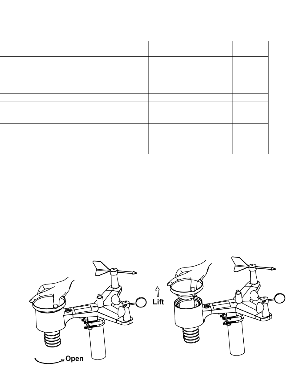
11. Maintenance
1. Clean the rain gauge once every 3 months. Rotate the funnel counter-clockwise and lift to
expose the rain gauge mechanism, and clean with a damp cloth. Remove any dirt, debris and
insects. If bug infestation is an issue, spray the array lightly with insecticide.
Figure 38
2. Clean the solar radiation sensor and solar panel every 3 months with damp cloth.
3. Replace batteries every 1-2 years. If left in too long, the batteries may leak due to

Version 1.0 Page 40
environmental challenges.
4. In snowy environments, spray the top of the weather station with anti-icing silicon spray to
prevent snow build up.
12. Troubleshooting Guide
Problem
Solution
Outdoor sensor array
does not communicate
to the display console.
The sensor array may have initiated properly and the data is registered by the
console as invalid, and the console must be reset. Press the reset button as
described in Figure 1.
With an open ended paperclip, press the reset button for 3 seconds to
completely discharge the voltage.
Take out the batteries and wait one minute, while covering the solar panel to
drain the voltage.
Put batteries back in and resync the console (Section 6.12) with the sensor
array about 10 feet away.
The LED next to the battery compartment will flash every 16 seconds. If
the LED is not flashing every 16 seconds…
Replace the batteries in the outside sensor array.
If the batteries were recently replaced, check the polarity. If the sensor is
flashing every 16 seconds, proceed to the next step.
There may be a temporary loss of communication due to reception loss
related to interference or other location factors,
or the batteries may have been changed in the sensor array and the console
has not been reset. The solution may be as simple as powering down and up
the console (remove AC power and batteries, wait 10 seconds, and reinsert
AC power and batteries).
Temperature sensor
reads too high in the
day time.
Make certain that the sensor array is not too close to heat generating sources
or strictures, such as buildings, pavement, walls or air conditioning units.
Use the calibration feature to offset installation issues related to radiant heat
sources. Reference Section 6.10.
Relative pressure does
not agree with official
reporting station
You may be viewing the absolute pressure, not the relative pressure.
Select the relative pressure. Make sure you properly calibrate the sensor to
an official local weather station. Reference Section 6.4 for details.
Rain gauge reports
rain when it is not
raining
An unstable mounting solution (sway in the mounting pole) may result in the
tipping bucket incorrectly incrementing rainfall. Make sure you have a
stable, level mounting solution.
Data not reporting to
Wunderground.com
1. Confirm your password or key is correct. It is the password you
registered on Wunderground.com. Your Wunderground.com
password cannot begin with a non-alphanumeric character (a
limitation of Wundeground.com, not the station). Example, $oewkrf
is not a valid password, but oewkrf$ is valid.
Version 1.0 Page 41
Problem
Solution
2. Confirm your station ID is correct. The station ID is all caps, and
the most common issue is substituting an O for a 0 (or visa versa).
Example, KAZPHOEN11, not KAZPH0EN11
3. Make sure the date and time is correct on the console. If incorrect,
you may be reporting old data, not real time data.
4. Make sure your time zone is set properly. If incorrect, you may be
reporting old data, not real time data.
5. Check your router firewall settings. The console sends data via Port
80.
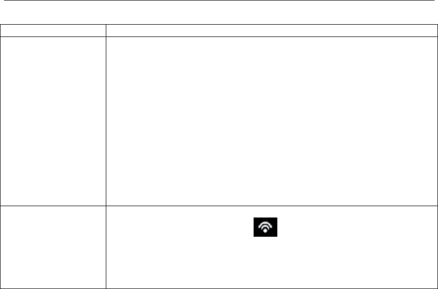
No WiFi connection
1. Check for WiFi symbol on the display. If wireless connectivity is
successful the WiFi icon will be displayed in the time field.
2. Make sure your modem WiFi settings are correct (network name,
and password).
13. Liability Disclaimer
Please help in the preservation of the environment and return used batteries to an authorized depot.
The electrical and electronic wastes contain hazardous substances. Disposal of electronic waste in wild
country and/or in unauthorized grounds strongly damages the environment.
Reading the “User manual” is highly recommended. The manufacturer and supplier cannot accept any
responsibility for any incorrect readings and any consequences that occur should an inaccurate reading
take place.
This product is designed for use in the home only as indication of weather conditions. This product is
not to be used for medical purposes or for public safety information.
The specifications of this product may change without prior notice.
This product is not a toy. Keep out of the reach of children.
No part of this manual may be reproduced without written authorization of the manufacturer.
14. FCC Statement
Statement according to FCC part 15.19:
This device complies with part 15 of the FCC rules. Operation is subject to the following two
conditions:
1. This device may not cause harmful interference.
Version 1.0 Page 42
2. This device must accept any interference received, including interference that may cause
undesired operation.
Statement according to FCC part 15.21:
Any changes or Modifications not expressly approved by this company could void the user's authority to
operate the equipment.
Statement according to FCC part 15.105:
NOTE: This equipment has been tested and found to comply with the limits for a Class B digital
device, pursuant to Part 15 of the FCC Rules. These limits are designed to provide reasonable
protection against harmful interference in a residential installation. This equipment generates, uses and
can radiate radio frequency energy and, if not installed and used in accordance with the instructions,
may cause harmful interference to radio communications.
However, there is no guarantee that interference will not occur in a particular installation. If this
equipment does cause harmful interference to radio or television reception, which can be determined
by turning the equipment off and on, the user is encouraged to try to correct the interference by one or
more of the following measures:
• Reorient or relocate the receiving antenna.
• Increase the separation between the equipment and receiver.
• Connect the equipment into an outlet on a circuit different from that to which the receiver is
connected.
• Consult the dealer or an experienced radio/TV technician for help.
This device complies with FCC radiation exposure limits set forth for an uncontrolled environment and
it also complies with Part 15 of the FCC RF Rules. This equipment must be installed and operated in
accordance with provided instructions and the antenna(s) used for this transmitter must be installed to
provide a separation distance of at least 20 cm from all persons and must not be co-located or operating in
conjunction with any other antenna or transmitter. End-users and installers must be provided with antenna
installation instructions and consider removing the no-collocation statement.