Fine Offset Electronics WH65BV1 Wireless weather station (Transmitter) User Manual
Fine Offset Electronics Co., Ltd. Wireless weather station (Transmitter)
UserManual.wiki
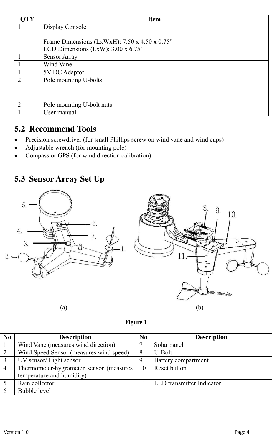
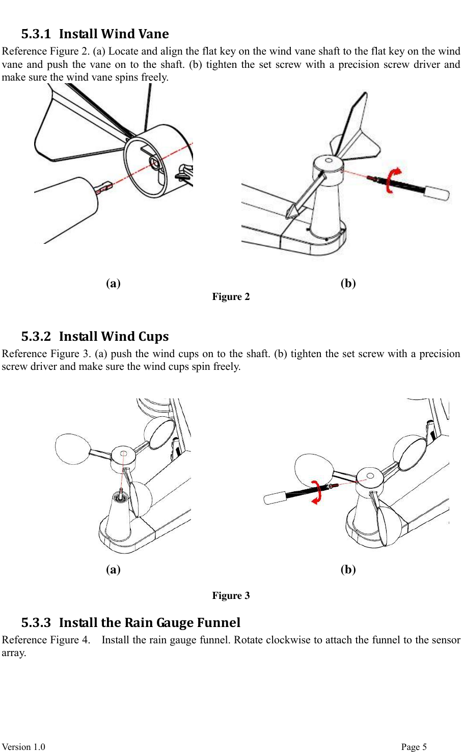
>
Fine Offset Electronics
>
WH65BV1 User Manual
User Manual
Navigation menu
Upload a User Manual
Namespaces
Wiki Guide
HTML
PDF
Info
Views
User Manual
Discussion / Help
Navigation
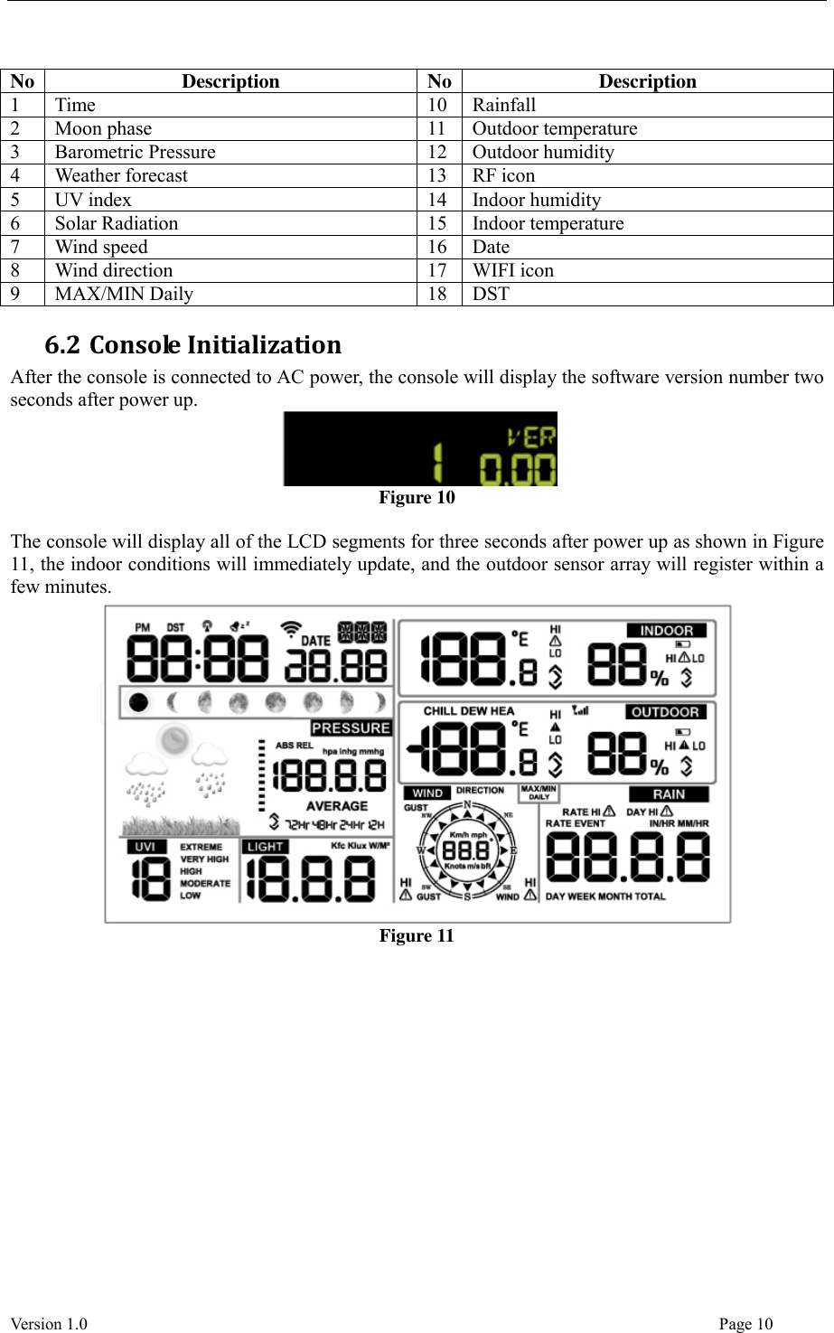

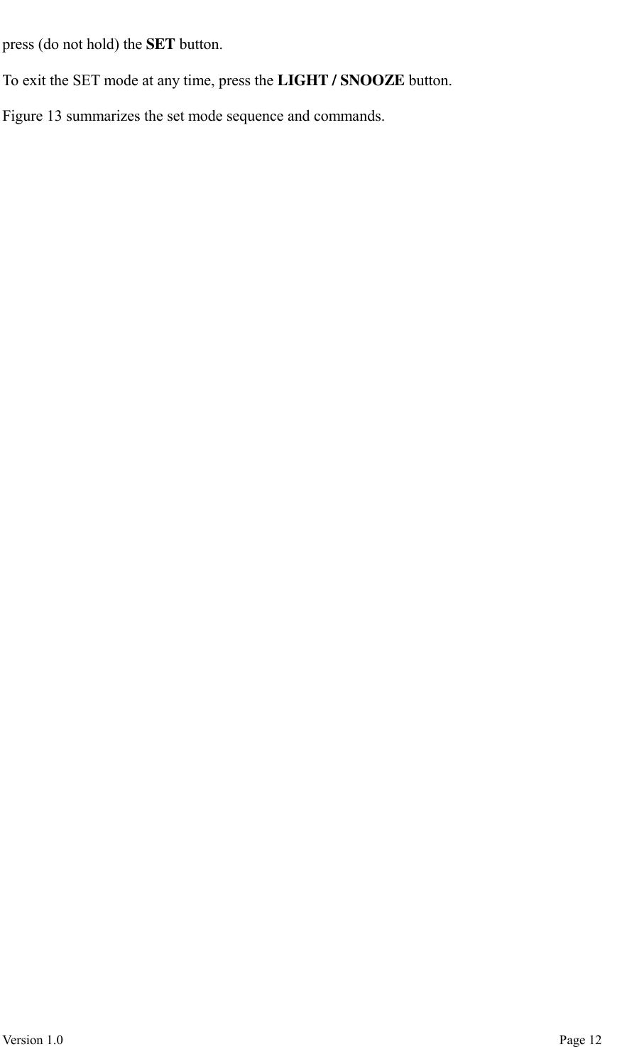
![Version 1.0 Page 13 Command Mode Settings Image [SET] + 2 seconds Enter Set Mode, Beep On or Off Press [WIND +] to switch OFF and ON. This will prevent the beep from sounding when pressing any button. [SET] Clear Max/Min Press [WIND +] to switch OFF and ON. When set to ON, the minimum and maximum values reset every day at midnight (00:00). When set to OFF, the minimum and maximum values must be reset manually. [SET] Daylight Savings Time (DST) Press [WIND +] to switch DST OFF and ON. Set to ON (most locations) if you observe daylight savings time, and the clock will automatically adjust twice per year. Set to OFF (Arizona and Hawaii) if you do not observe DST. [SET] Time Zone Press [WIND +] or [PRESSURE -] to adjust up or down (-12 to 12). The default time zone is -5 (EST). To find your time zone settings, please reference Figure 14. [SET] 12 hour / 24 Hour Format Press [WIND +] to switch hour format between 12 hour and 24 hour format. [SET] Hour Press [WIND +] or [PRESSURE -] to adjust hour up or down. [SET] Minute Press [WIND +] or [PRESSURE -] to adjust minute up or down. [SET] Date Format Press [WIND +] to switch between MM-DD (month-day) and DD-MM (day-month) [SET] Year Press [WIND +] or [PRESSURE -] to adjust year up or down [SET] Month Press [WIND +] or [PRESSURE -] to adjust month up or down [SET] Day Press [WIND +] or [PRESSURE -] to adjust day up or down [SET] Pressure Units of Measure Press [WIND +] to change units of measure between hpa, mmHg or inHg.](https://usermanual.wiki/Fine-Offset-Electronics/WH65BV1/User-Guide-3627171-Page-13.png)
![Version 1.0 Page 14 [SET] Relative Pressure Calibration Press [WIND +] or [PRESSURE -] to adjust relative pressure up or down Reference Section 6.4.4 for details on calibration of relative pressure. [SET] Light Units of Measure Press [WIND +] to change light units of measure between lux, fc, or w/m2 [SET] Temperature Units of Measure Press [WIND +] to change temperature units of measure between °F and °C. [SET] Wind Units of Measure Press [WIND +] to change wind units of measure between km/h, mph, knots, m/s and bft. [SET] Rain Units of Measure Press [WIND +] to change rain units of measure between in and mm. [SET] Hemisphere Press [WIND +] to change hemisphere between NTH (northern) and STH (southern). This setting effects the moon phase display. [SET] Exit Set Mode [SET] + 2 seconds means press and hold the SET button for two seconds. [SET] means press the SET button. Figure 13 6.3.1 Time Zones The following table summarizes time zones around the world. Hours from GMT Time Zone Cities -12 IDLW: International Date Line West --- -11 NT: Nome Nome, AK -10 AHST: Alaska-Hawaii Standard CAT: Central Alaska HST: Hawaii Standard Honolulu, HI -9 YST: Yukon Standard Yukon Territory -8 PST: Pacific Standard Los Angeles, CA, USA -7 MST: Mountain Standard Denver, CO, USA -6 CST: Central Standard Chicago, IL, USA -5 EST: Eastern Standard New York, NY, USA -4 AST: Atlantic Standard Caracas -3 --- São Paulo, Brazil -2 AT: Azores Azores, Cape Verde Islands -1 WAT: West Africa ---](https://usermanual.wiki/Fine-Offset-Electronics/WH65BV1/User-Guide-3627171-Page-14.png)
![Version 1.0 Page 15 Hours from GMT Time Zone Cities 0 GMT: Greenwich Mean WET: Western European London, England 1 CET: Central European Paris, France 2 EET: Eastern European Athens, Greece 3 BT: Baghdad Moscow, Russia 4 --- Abu Dhabi, UAE 5 --- Tashkent 6 --- Astana 7 --- Bangkok 8 CCT: China Coast Bejing 9 JST: Japan Standard Tokyo 10 GST: Guam Standard Sydney 11 --- Magadan 12 IDLE: International Date Line East NZST: New Zealand Standard Wellington, New Zealand Figure 14 6.4 Barometric Pressure Display 6.4.1 Viewing Absolute vs. Relative Pressure To switch between absolute and relative pressure, press and hold the [PRESSURE -] button for two seconds. Absolute pressure is the measured atmospheric pressure, and is a function of altitude, and to a lesser extent, changes in weather conditions. Absolute pressure is not corrected to sea-level conditions. Relative pressure is corrected to sea-level conditions. For further discussion of relative pressure and calibration, reference Section 6.4.4. 6.4.2 Rate of Change of Pressure Graph The rate of change of pressure graphic is shown to the left of the barometric pressure and signifies the difference between the daily average pressure and the 30 day average (in hPa).](https://usermanual.wiki/Fine-Offset-Electronics/WH65BV1/User-Guide-3627171-Page-15.png)
![Version 1.0 Page 16 Figure 15 6.4.3 Viewing Pressure History Press the [PRESSURE -] button to view the 12 hour, 24 hour, 48 hour and 72 hour pressure average. 6.4.4 Relative Pressure Calibration Discussion To compare pressure conditions from one location to another, meteorologists correct pressure to sea-level conditions. Because the air pressure decreases as you rise in altitude, the sea-level corrected pressure (the pressure your location would be at if located at sea-level) is generally higher than your measured pressure. Thus, your absolute pressure may read 28.62 inHg (969 mb) at an altitude of 1000 feet (305 m), but the relative pressure is 30.00 inHg (1016 mb). The standard sea-level pressure is 29.92 in Hg (1013 mb). This is the average sea-level pressure around the world. Relative pressure measurements greater than 29.92 inHg (1013 mb) are considered high pressure and relative pressure measurements less than 29.92 inHg are considered low pressure. To determine the relative pressure for your location, locate an official reporting station near you (the internet is the best source for real time barometer conditions, such as Weather.com or Wunderground.com), and set your weather station to match the official reporting station. 6.5 Rain Display 6.5.1 Rain Increments of Measure Press the RAIN button to switch between Rain Rate (in/hr), Rain Event, Rain Day, Rain Week, Rain Month, and Rain Total. 6.5.2 Resetting Rain To reset the rain totals, press and hold the RAIN button for two seconds. Resetting the weekly rain also resets the daily rain. Resetting the monthly rain also resets the daily and weekly rain.](https://usermanual.wiki/Fine-Offset-Electronics/WH65BV1/User-Guide-3627171-Page-16.png)
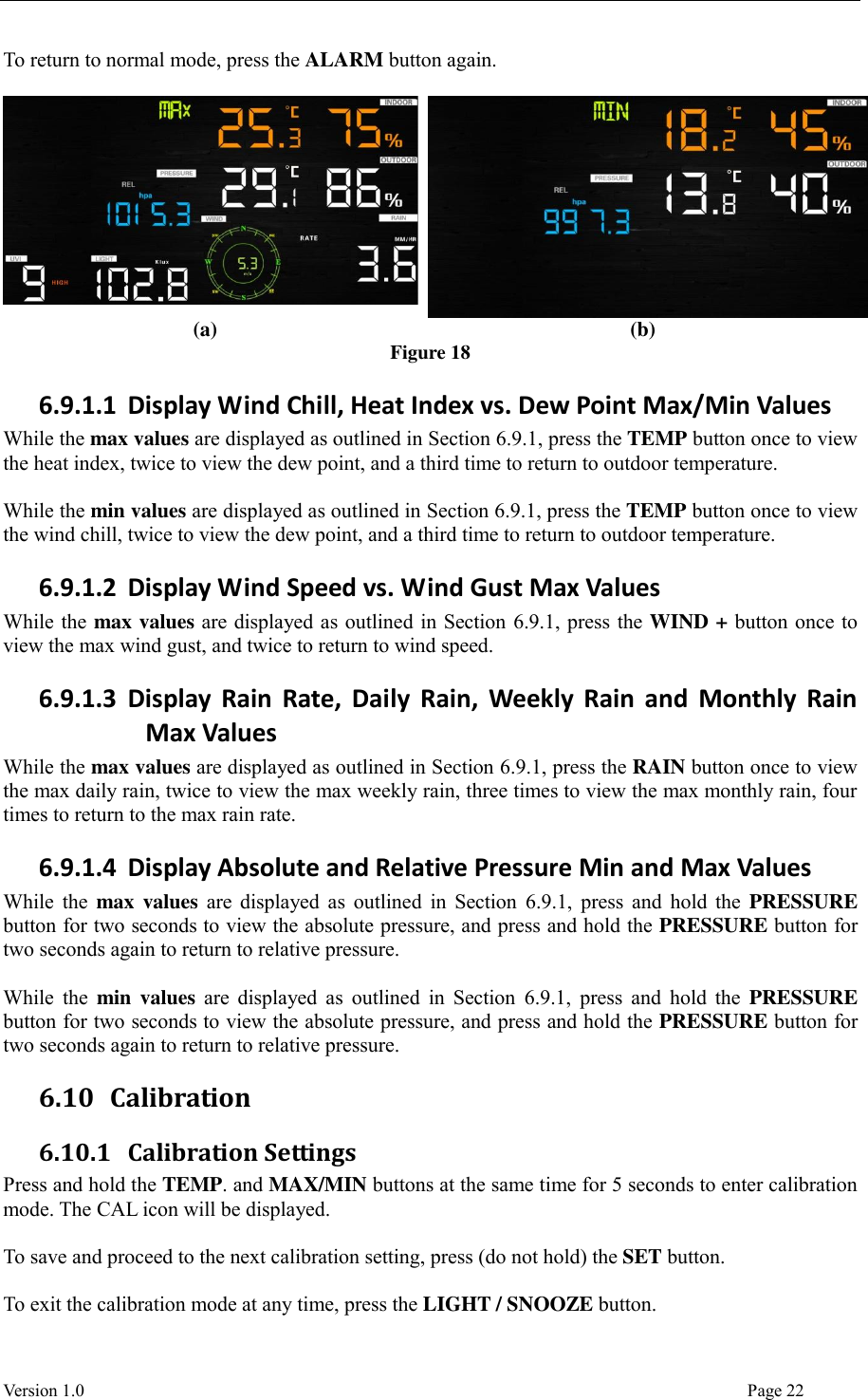
![Version 1.0 Page 17 Resetting the total rain also resets the monthly, weekly and daily rain. 6.5.3 Increments of Rain Definitions Rain rate is defined as the last 10 minutes of rainfall, multiplied by six (10 minutes x 6 = 1 hour). This is also referred to as instantaneous rain per hour. Rain event is defined as continuous rain, and resets to zero if rainfall accumulation is less than 10 mm (0.039 in) in a 24 hour period. Daily Rain is defined as the rainfall since midnight (00:00). Weekly Rain is defined as the calendar week total, and resets on Sunday morning at midnight (Sunday thru Saturday). Monthly Rain is defined as the calendar month total, and resets on the first day of the Month. Total Rain is defined as the running total since station was powered up. 6.6 Wind Display Press the [WIND +] button to switch between average wind speed, wind gust and wind direction. Wind speed is defined as the average wind speed in the 16 second update period. Wind gust is defined as the peak wind speed in the 16 second update period. 6.7 Temperature Display If temperature is lower than minimum range, the temperature field will display dashes (--.-). If temperature is higher than maximum range, the temperature field will display dashes (--.-). 6.7.1 Wind Chill, Dew Point and Heat Index Display Press the [TEMP] button to switch between Outdoor Temperature, Wind Chill, Heat Index, Dew Point. 6.8 Alarms 6.8.1 Viewing High and Low Alarms To view the high alarm settings, press (do not hold) the ALARM button, and the high alarms will be displayed, as shown in Figure 16 (a). To view the low alarm settings, press the ALARM button again, and the low alarms will be displayed, as shown in Figure 16 (b). To return to normal mode, press the ALARM button again. (a) (b) Figure 16](https://usermanual.wiki/Fine-Offset-Electronics/WH65BV1/User-Guide-3627171-Page-17.png)
![Version 1.0 Page 19 Command Mode Settings [ALARM] + 2 seconds Enter Alarm Set Mode, Alarm Hour Press [WIND +] or [PRESSURE -] to adjust alarm hour up or down. Press [ALARM] to turn the time alarm on or off. When the alarm is on, the alarm time icon will appear. [SET] Alarm Minute Press [WIND +] or [PRESSURE -] to adjust alarm minute up or down. Press [ALARM] to turn the time alarm on. The alarm time icon will appear. Press [ALARM] again to turn the time alarm off. The alarm time icon will disappear. [SET] Alarm High Indoor Temperature Press [WIND +] or [PRESSURE -] to adjust alarm value up or down. Press [ALARM] to turn the alarm on. The alarm icon will appear. Press [ALARM] to turn the alarm off. The alarm icon will disappear. [SET] Alarm Low Indoor Temperature Press [WIND +] or [PRESSURE -] to adjust alarm value up or down. Press [ALARM] to turn the alarm on. The alarm icon will appear. Press [ALARM] to turn the alarm off. The alarm icon will disappear. [SET] Alarm High Indoor Humidity Press [WIND +] or [PRESSURE -] to adjust alarm value up or down. Press [ALARM] to turn the alarm on. The alarm icon will appear. Press [ALARM] to turn the alarm off. The alarm icon will disappear.](https://usermanual.wiki/Fine-Offset-Electronics/WH65BV1/User-Guide-3627171-Page-19.png)
![Version 1.0 Page 20 [SET] Alarm Low Indoor Humidity Press [WIND +] or [PRESSURE -] to adjust alarm value up or down. Press [ALARM] to turn the alarm on. The alarm icon will appear. Press [ALARM] to turn the alarm off. The alarm icon will disappear. [SET] Alarm High Outdoor Temperature Press [WIND +] or [PRESSURE -] to adjust alarm value up or down. Press [ALARM] to turn the alarm on. The alarm icon will appear. Press [ALARM] to turn the alarm off. The alarm icon will disappear. [SET] Alarm Low Outdoor Temperature Press [WIND +] or [PRESSURE -] to adjust alarm value up or down. Press [ALARM] to turn the alarm on. The alarm icon will appear. Press [ALARM] to turn the alarm off. The alarm icon will disappear. [SET] Alarm High Outdoor Humidity Press [WIND +] or [PRESSURE -] to adjust alarm value up or down. Press [ALARM] to turn the alarm on. The alarm icon will appear. Press [ALARM] to turn the alarm off. The alarm icon will disappear. [SET] Alarm Low Outdoor Humidity Press [WIND +] or [PRESSURE -] to adjust alarm value up or down. Press [ALARM] to turn the alarm on. The alarm icon will appear. Press [ALARM] to turn the alarm off. The alarm icon will disappear.](https://usermanual.wiki/Fine-Offset-Electronics/WH65BV1/User-Guide-3627171-Page-20.png)
![Version 1.0 Page 21 [SET] Alarm High Wind Speed Press [WIND +] or [PRESSURE -] to adjust alarm value up or down. Press [ALARM] to turn the alarm on. The alarm icon will appear. Press [ALARM] to turn the alarm off. The alarm icon will disappear. [SET] Alarm High Wind Gust Press [WIND +] or [PRESSURE -] to adjust alarm value up or down. Press [ALARM] to turn the alarm on. The alarm icon will appear. Press [ALARM] to turn the alarm off. The alarm icon will disappear. [SET] Alarm High Rain Rate Press [WIND +] or [PRESSURE -] to adjust alarm value up or down. Press [ALARM] to turn the alarm on. The alarm icon will appear. Press [ALARM] to turn the alarm off. The alarm icon will disappear. [SET] Alarm High Daily Rain Press [WIND +] or [PRESSURE -] to adjust alarm value up or down. Press [ALARM] to turn the alarm on. The alarm icon will appear. Press [ALARM] to turn the alarm off. The alarm icon will disappear. [SET] Exit alarm settings mode. [ALARM] + 2 seconds means press and hold the ALARM button for two seconds. [ALARM] means press the ALARM button. Figure 17 6.9 Max/Min Mode 6.9.1 Viewing Max/Min Values To view the max value, press (do not hold) the MAX/MIN button, and the max values will be displayed, as shown in Figure 18 (a). To view the low alarm settings, press the MAX/MIN button again, and the min values will be displayed, as shown in Figure 18 (b).](https://usermanual.wiki/Fine-Offset-Electronics/WH65BV1/User-Guide-3627171-Page-21.png)
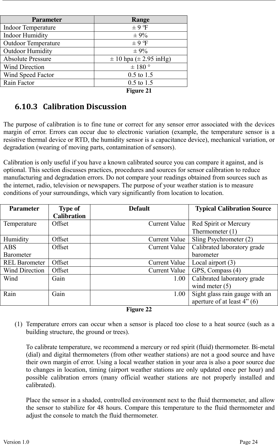
![Version 1.0 Page 23 Figure 19 Figure 20 summarizes the set mode sequence and commands. Command Mode Settings TEMP. and MAX/MIN + 5 seconds Enter Calibration Mode, Indoor Temperature Press [WIND +] or [PRESSURE -] to adjust the indoor temperature up or down. To restore to factory default, press [ALARM]. [SET] Indoor Humidity Press [WIND +] or [PRESSURE -] to adjust the indoor humidity up or down. To restore to factory default, press [ALARM]. [SET] Outdoor Temperature Press [WIND +] or [PRESSURE -] to adjust the outdoor temperature up or down. To restore to factory default, press [ALARM]. [SET] Outdoor Humidity Press [WIND +] or [PRESSURE -] to adjust the outdoor humidity up or down. To restore to factory default, press [ALARM]. [SET] Absolute Pressure Press [WIND +] or [PRESSURE -] to adjust the absolute pressure up or down. To restore to factory default, press [ALARM]. Note: The absolute pressure calibration affects the relative pressure by the same amount. It is recommend you calibrate the relative pressure only, per Section 6.3. [SET] Wind Direction Press [WIND +] or [PRESSURE -] to adjust the wind direction up or down. To restore to factory default, press [ALARM]. [SET] Wind Speed Factor Press [WIND +] or [PRESSURE -] to adjust the wind speed factor up or down. To restore to factory default, press [ALARM]. [SET] Rain Factor Press [WIND +] or [PRESSURE -] to adjust the rain factor up or down. To restore to factory default, press [ALARM]. [SET] Exit calibration mode Figure 20 6.10.2 Calibration Ranges The following table summarizes the permissible calibration ranges.](https://usermanual.wiki/Fine-Offset-Electronics/WH65BV1/User-Guide-3627171-Page-23.png)