Fiplex Communications DH4 DH4 User Manual TETRA User s Manual
Fiplex Communications Inc DH4 TETRA User s Manual
UserManual.wiki
>
Fiplex Communications
>
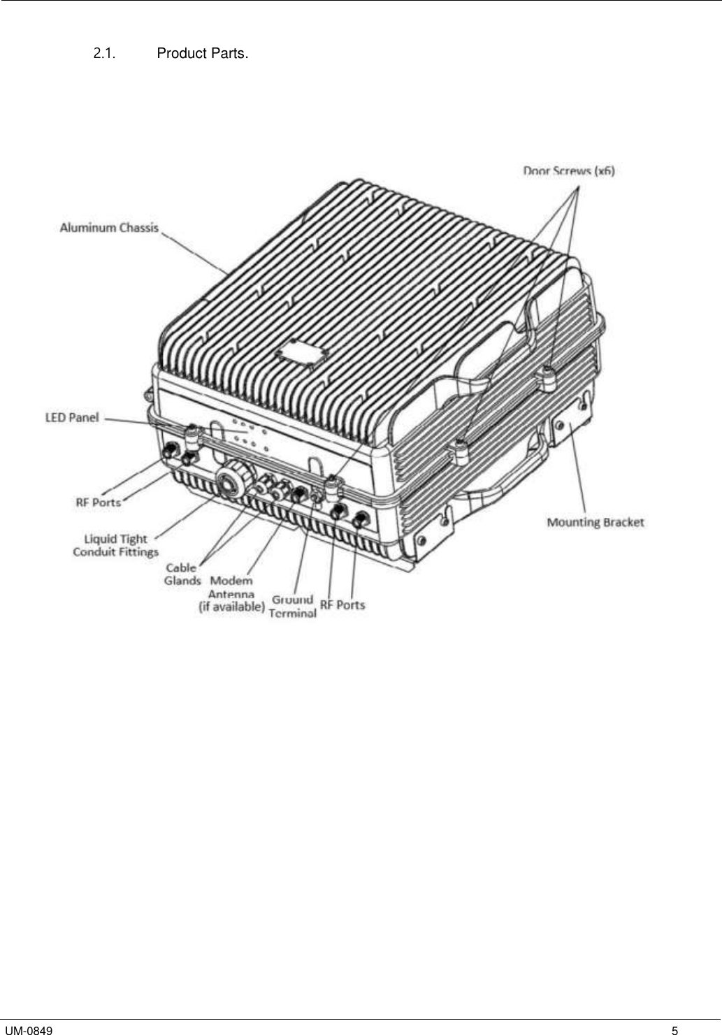
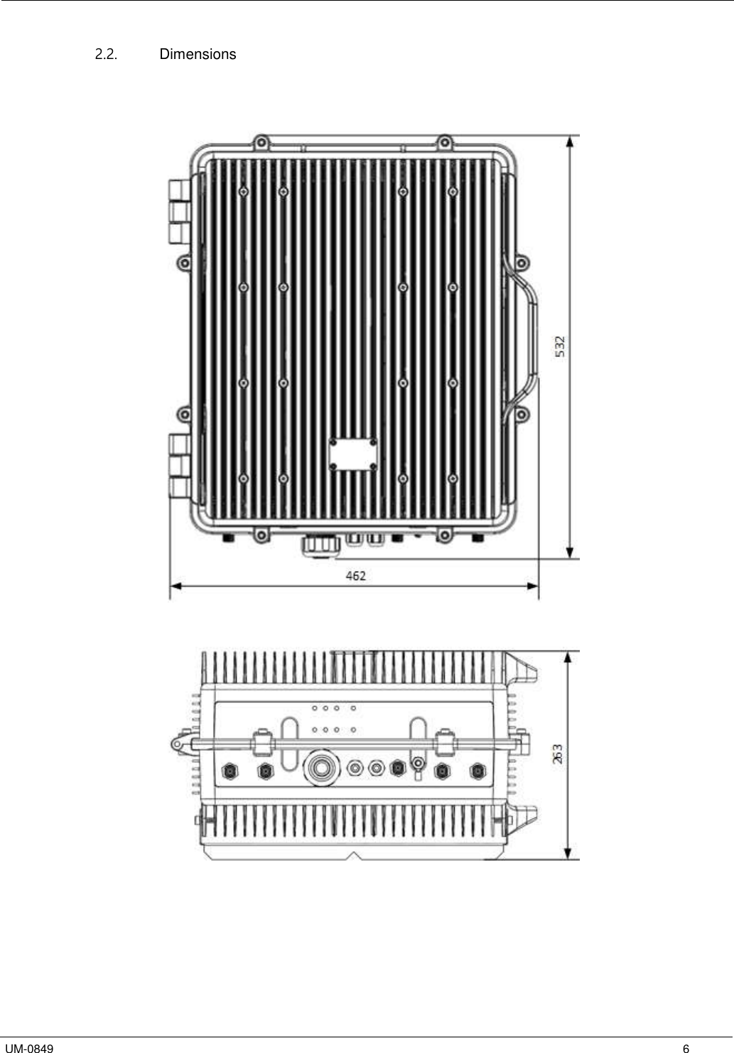
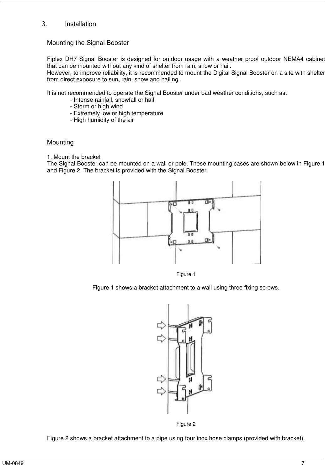
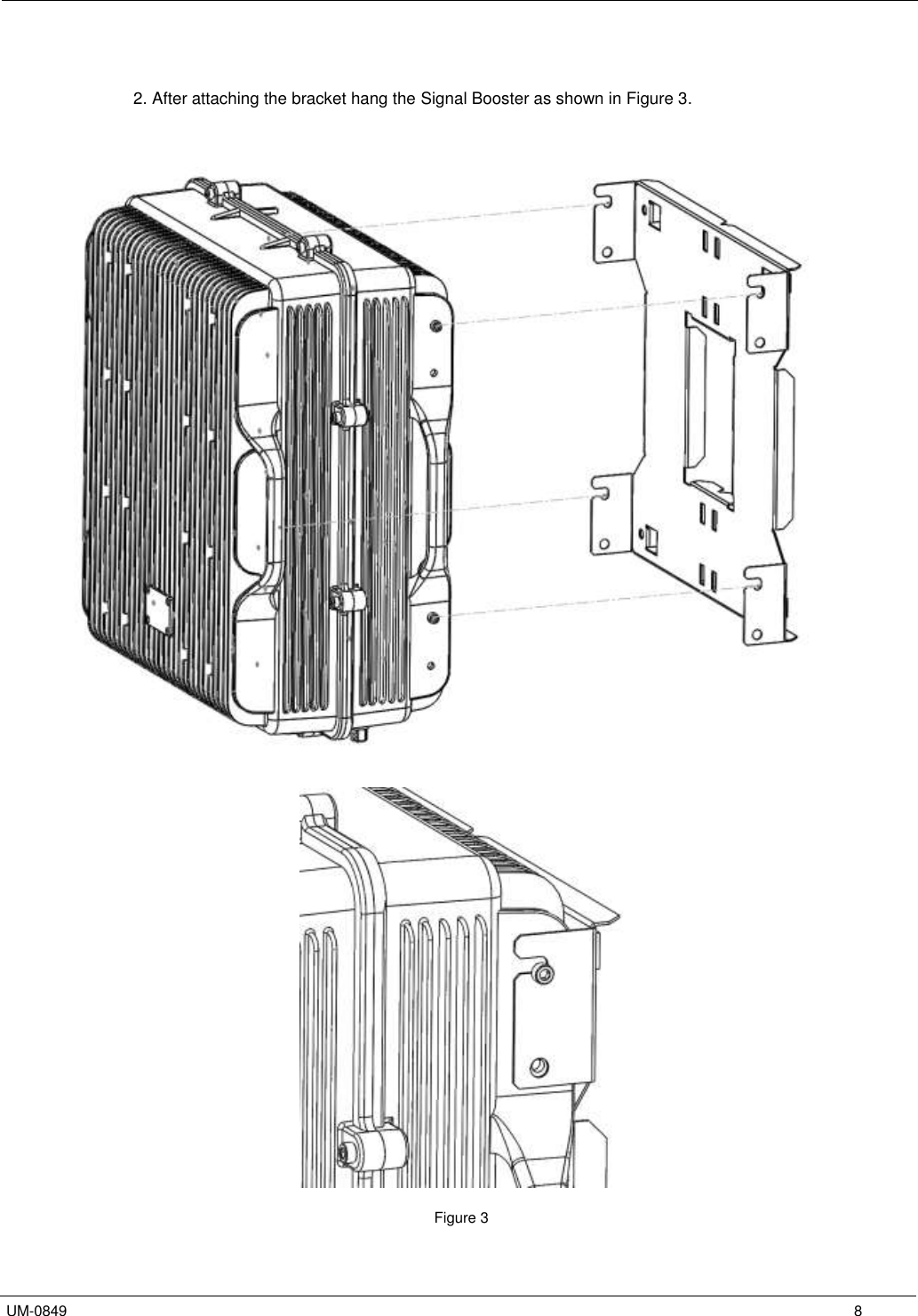
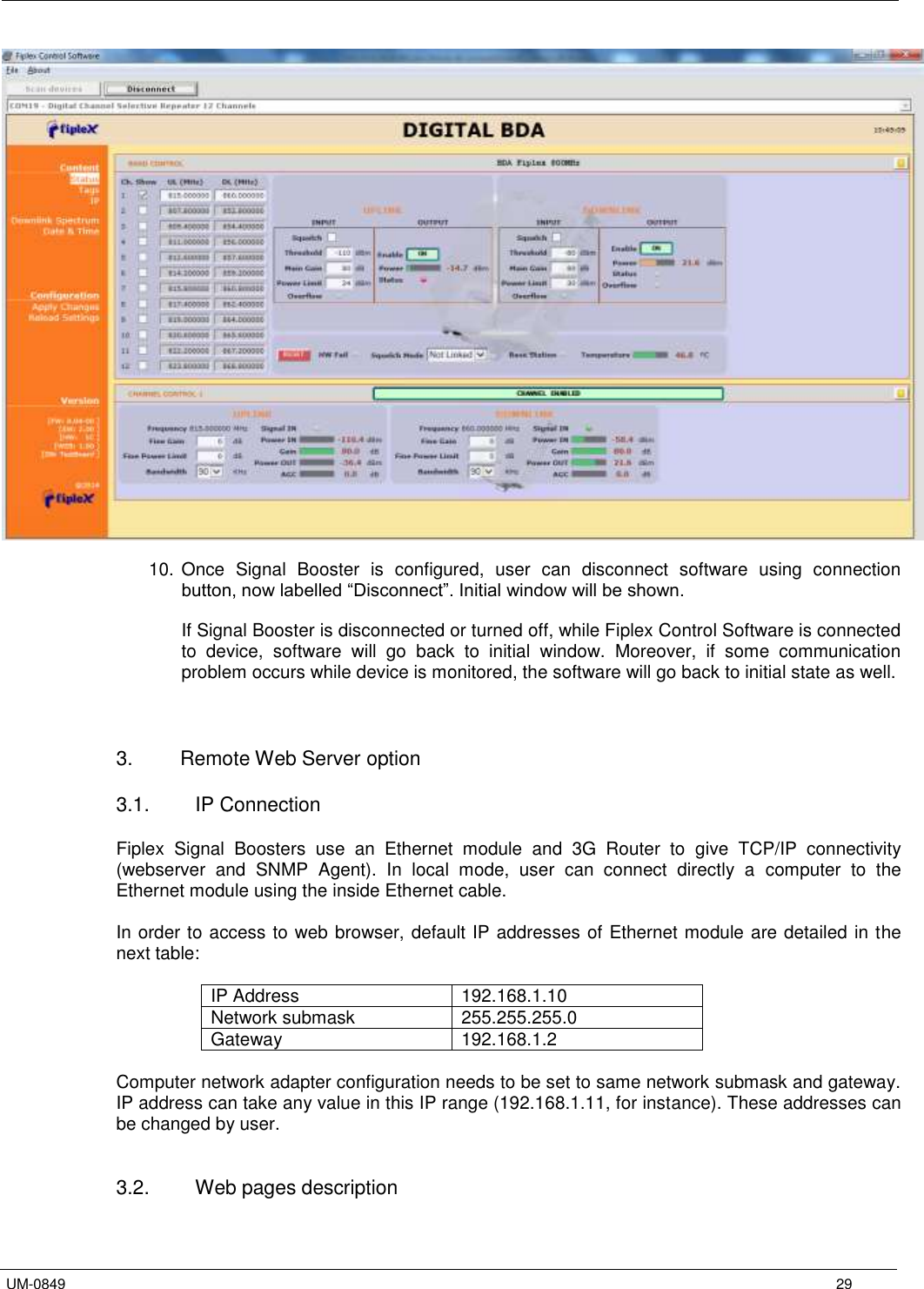
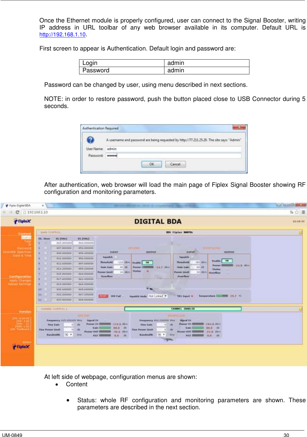
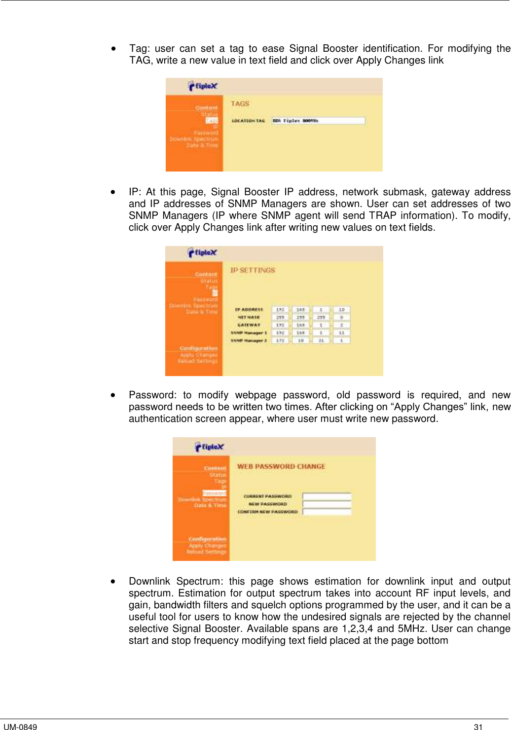
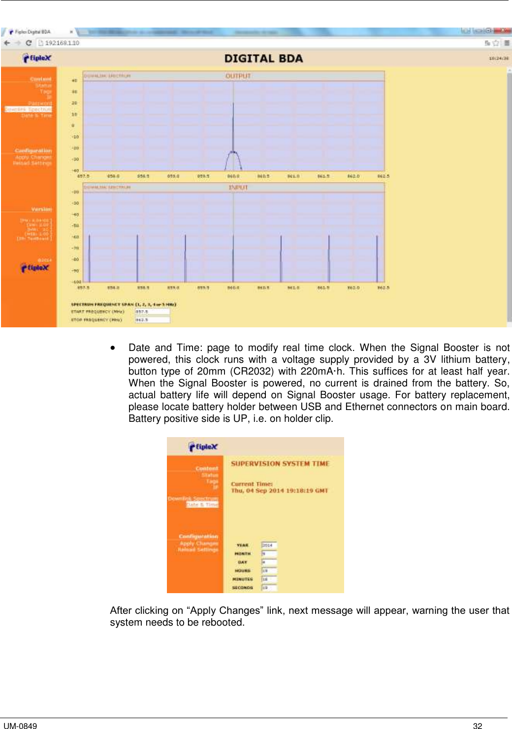
DH4 User Manual
User Manual
Navigation menu
Upload a User Manual
Namespaces
Wiki Guide
HTML
PDF
Info
Views
User Manual
Discussion / Help
Navigation