Fiplex Communications DH4L00-M BI-DIRECTIONAL AMPLIFIER User Manual TETRA User s Manual
Fiplex Communications Inc BI-DIRECTIONAL AMPLIFIER TETRA User s Manual
user manual
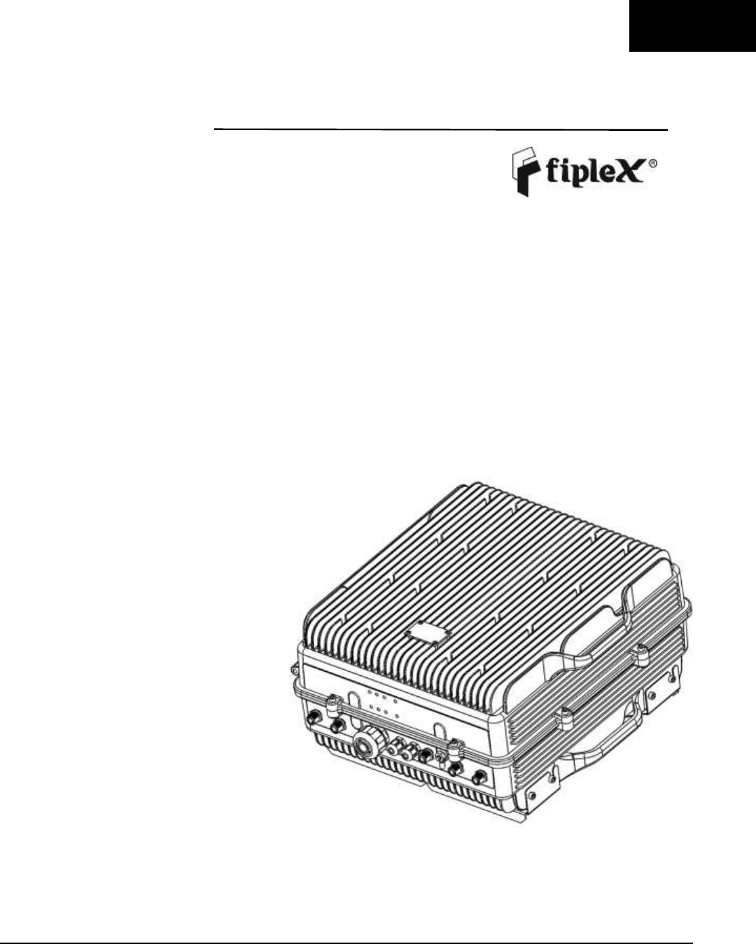
English
DH4L – UHF Low Digital Fiber DAS
User & Installation Manual

UM-0840 II
Document History
Description
Revision
Date Issued
Original version
1.0
July 3rd, 2014
General Review
2.0
March 2nd, 2016

UM-0840 III
About this manual
This manual describes installation, commissioning, operation and maintenance of the Fiplex UHF Low Digital Fiber DAS,
and Fiplex Control Software (FCS). The hardware included in this manual corresponds to the Digital Master Unit DH4L00-
M (DM), and Digital Remote Unit DH4L37-R (DR).
The first part of the manual describes the Digital Fiber DAS hardware and the second part describes the software.
Hardware and software mentioned in this manual are subjected to continuous development and improvement. Consequently,
there may be minor discrepancies between the information in the manual and the performance and design of the hardware
and software. Specifications, dimensions and other statements mentioned in this manual are subject to change without notice.
This manual or parts of it may not be reproduced without the written permission of Fiplex Communications Inc.
Infringements will be prosecuted. All rights reserved.
Copyright © Fiplex Communications Inc, Miami, 2016.

UM-0840 IV
Contents
Part 1 HARDWARE ................................................................. ¡Error! Marcador no definido.
1. Safety ........................................................................................................ ¡Error! Marcador no definido.
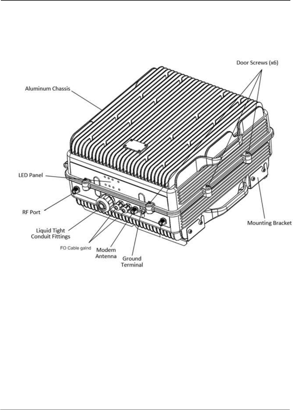
2. Product Description .................................................................................................................................. 4
2.1 Digital Master Unit Ports ........................................................................................................................... 5
2.2 Digital Remote Unit Ports ......................................................................................................................... 6
2.3 Connection Diagram ................................................................................................................................. 7
2.4 FO Connection .......................................................................................................................................... 8
2.4.1 FO Connection in Master Unit .................................................................................................................. 8
2.4.2 FO Connection in Remote Unit ................................................................................................................. 9
2.5 Interface with signal source .................................................................................................................... 10
3 Installation ............................................................................................................................................... 12
Mounting ........................................................................................................................................................ 12
Opening and Closing the Cabinet.................................................................................................................. 15
Nema4X considerations ................................................................................................................................ 19
4 Commissioning ....................................................................................................................................... 20
4.1 Connection step by step ......................................................................................................................... 20
4.2 Starting Operation ................................................................................................................................... 23
4.3 Status Indicators .................................................................................................................................... 27
4.4 Laboratory Measurements ...................................................................................................................... 28
Part 2 SOFTWARE ............................................................................................................ 29
5 Introduction ................................................................................................................................................. 29
6 USB Software ............................................................................................................................................. 29
6.1 Software description (Digital Master) .................................................................................................... 29
6.2 RF parameters description (Digital Master) ........................................................................................... 31
6.3 Software description (Remote Unit) ....................................................................................................... 36
7 Local Software. Installation and troubleshooting ....................................................................................... 37
7.1 Installation .............................................................................................................................................. 37

UM-0840 V
Abbreviations
AGC Automatic Gain Control
AMPS Advanced Mobile Phone Service
ARFCN Absolute Radio Frequency Channel Number
BCCH Broadcast Control Channel (GSM broadcast channel time slot)
BS Base Station, BS antenna = towards the base station
CDMA Code Division Multiple Access
DC Direct Current
DCS Digital Communication System (same as PCN)
DL Downlink signal direction (from base station via repeater to mobile station)
DPLX Duplex filter
EEPROM Electrical Erasable Programmable Read Only Memory
EGSM Extended Global System for Mobile communication
ETACS Extended Total Access Communication System
ETSI European Telecommunications Standard Institute
FCS Fiplex Control Software
GSM Global System for Mobile communication
HW Hardware
LED Light Emitting Diode
LNA Low Noise Amplifier, uplink and downlink
MS Mobile Station, MS antenna = towards the mobile station
OMS Operation and Maintenance System
OL Overload
PA Power Amplifier
PCN Personal Communication Network (same as DCS)
PCS Personal Communication System
PS Power Supply
RF Radio Frequency
RSSI Received Signal Strength Indication
SW Software
TDMA Time Division Multiple Access
UL Uplink signal direction (from mobile station via repeater to base station)
WEEE Waste of Electric and Electronic Equipment
User Manual– Digital DAS 1
Part 1 HARDWARE
1. Safety
Dangerous Voltage Warning
Any personnel involved in installation, operation or service of Fiplex Digital Fiber DAS must understand
and obey the following:
The power supply unit in Digital Fiber DAS supplied from the mains contains dangerous voltage level,
which can cause electric shock. Switch the mains off prior to any work in such a Digital Fiber DAS. Any
local regulations are to be followed when servicing Digital Fiber DAS.
Authorized service personnel only are allowed to service Digital Fiber DAS while the main is switched on.
Any Digital Fiber DAS, including this Digital Fiber DAS, will generate radio signals and thereby give rise to
electromagnetic fields that may be hazardous to the health of any person who is extensively exposed to the
signals at the immediate proximity of the Digital Fiber DAS and the Digital Fiber DAS antennas.
Radiation Hazard Warning
R&TTE Compliance Statement
This equipment complies with the appropriate essential requirements of Article 3 of the R&TTE Directive
1999/5/EC.
Station Ground
BTS chassis, Digital Fiber DAS, feeders, donor antenna, service antenna/s and auxiliary equipment (splitters,
tabs, .etc) are required to be bonded to protective grounding using the bonding stud or screw provided with each
unit.
Electrostatic Discharge
Static electricity means no risk of personal injury but it can severely damage essential parts of the Digital Fiber
DAS, if not handled carefully.
Parts on the printed circuit boards as well as other parts in the Digital Fiber DAS are sensitive to electrostatic
discharge.
Never touch printed circuit boards or uninsulated conductor surfaces unless absolutely necessary.
If you must handle printed circuit boards or uninsulated conductor surfaces, use ESD protective equipment, or
first touch the Digital Fiber DAS chassis with your hand and then do not move your feet on the floor.
Never let your clothes touch printed circuit boards or uninsulated conductor surfaces.
Disposal of Electric and Electronic Waste
Pursuant to the WEEE EU Directive electronic and electrical waste must not be disposed of with unsorted
waste. Please contact your local recycling authority for disposal of this product.
UM-0840 2
FCC Compliance
This is a Class B signal booster
WARNING: This is a 90.219 Class B device. This is NOT a CONSUMER device. It is designed
for installation by FCC LICENSEES and QUALIFIED INSTALLERS. You MUST have an FCC
LICENSE or express consent of an FCC Licensee to operate this device. You MUST register
Class B signal boosters (as defined in 47 CFR 90.219) online at www.fcc.gov/signal-
boosters/registration. Unauthorized use may result in significant forfeiture penalties, including
penalties in excess of $100,000 for each continuing violation. The installation procedure must
result in the signal booster complying with FCC requirements 90.219(d). In order to meet FCC
requirements 90.219(d), it may be necessary for the installer to reduce the UL and/or DL output
power for certain installations.
ATTENTION: This device complies with Part 15 of the FCC rules. Operation is subject
to the following two conditions: (1) this device may not cause harmful interference and
(2) this device must accept any interference received, including interference that may
cause undesired operation.
ATTENTION: FCC regulation mandate that the ERP of type B signal boosters should
not exceed 5W. This Digital Fiber DAS has a maximum DL composite output power of
5W (+37dBm) and UL composite output power of +24dBm, therefore the gain of the
DL antenna should be of 0dBi or less and maintain a minimum separation of 55 cm
from all persons, and the gain of the UL antenna should be 13dBi or less and maintain
a minimum separation of 55 cm from all persons.
IC Compliance
As per RSS 131 Issue 2:
Nominal passband gain: 80dB max
Nominal bandwidth: 90 kHz maximum for Canada market
Rated mean output power: +37dBm maximum in DL and +24dBm maximum in UL
Input and Output impedances: 50 ohms
The Manufacturer's rated output power of this equipment is for single carrier operation. For
situations when multiple carrier signals are present, the rating would have to be reduced by 3.5
dB, especially where the output signal is re-radiated and can cause interference to adjacent band
users. This power reduction is to be by means of input power or gain reduction and not by an
attenuator at the output of the device.
RF Exposure Statement for ISED: “This device complies with Health Canada’s Safety Code. The
installer of this device should ensure that RF radiation is not emitted in excess of the Health
Canada’s requirement. Information can be obtained at http://www.hc-sc.gc.ca/ewh-
semt/pubs/radiation/radio_guide-lignes_direct/index-eng.php”

UM-0840 3
The antenna/s used for this transmitter must be installed to provide a separation of at least 55 cm
in DL and 55 cm in UL from all persons and must not be collocated or operating in conjunction
with any other antenna or transmitter. Changes or modifications not expressly approved by the
party responsible for compliance could void the user’s authority to operate the equipment.
Selon RSS 131 Issue 2:
• Gain de bande passante nominal: 80dB max
• Bande passante nominale: 90kHz maximum pour le marché canadien
• Puissance nominale de sortie moyenne: + 37dBm maximum en DL et +24dBm maximum en UL.
• Impédances d'entrée et de sortie: 50 ohms
La puissance de sortie nominale du fabricant de cet équipement est pour le fonctionnement d'une
seule porteuse. Pour les situations où plusieurs signaux de porteuse sont présents, la cote devrait
être réduite de 3,5 dB, en particulier lorsque le signal de sortie est ré-irradié et peut causer des
interférences aux utilisateurs de bande adjacents. Cette réduction de puissance doit se faire au
moyen d'une puissance d'entrée ou d'une réduction de gain et non pas par un atténuateur à la
sortie du dispositif.
Déclaration d'exposition RF pour ISED: «Cet appareil est conforme au Code de sécurité de Santé
Canada. L'installateur de cet appareil doit s'assurer que les rayonnements RF ne sont pas émis
au-delà de l'exigence de Santé Canada. Vous pouvez obtenir de l'information à l'adresse
http://www.hc-sc.gc.ca/ewh-semt/pubs/radiation/radio_guide-lignes_direct/index-fra.php.
L'antenne utilisée pour cet émetteur doit être installée de manière à assurer une séparation d'au
moins 55 cm dans DL et 55 cm dans UL de toutes les personnes et ne doit pas être collocée ni
fonctionner avec une autre antenne ou émetteur. Les changements ou modifications non
expressément approuvés par la partie responsable de la conformité pourraient annuler
l'autorisation de l'utilisateur d'utiliser l'équipement.

UM-0840 4
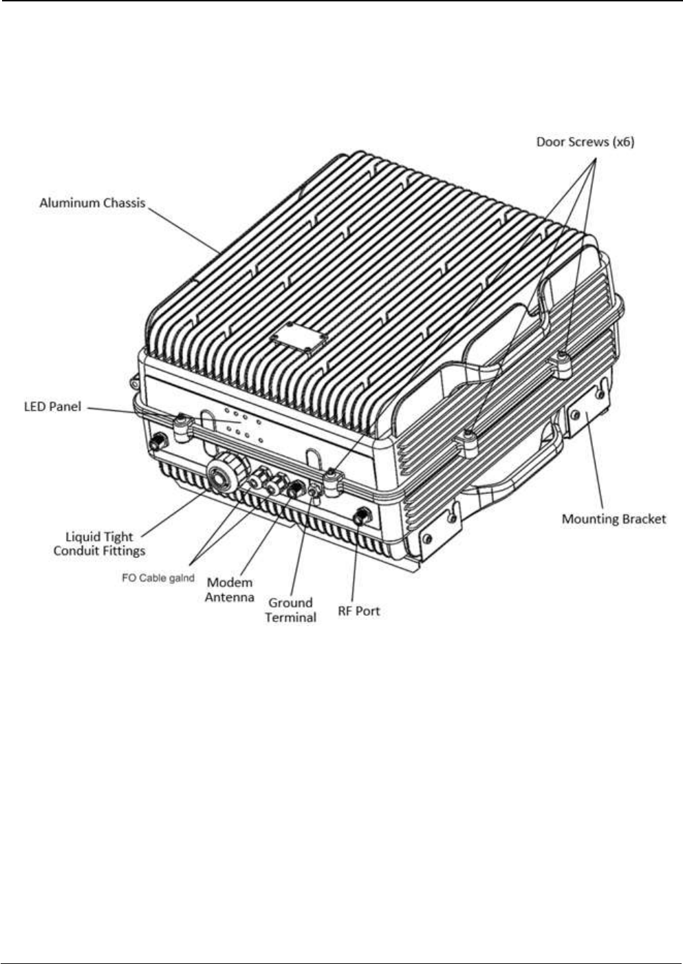
Product Description.
The UHF Low Fiplex Digital DAS has a modular structure that consists in two different modules in star
configuration, the Digital Master Unit model DH4L00-M (center of the star) and Digital Remote Unit model
DH4L37-R (legs of the star) that can operate in the UHF frequency range of 406-424MHz. Each one of the
different modules is enclosed in the same or equivalent case, therefore, product description and installing
instruction sections are valid for all of them.
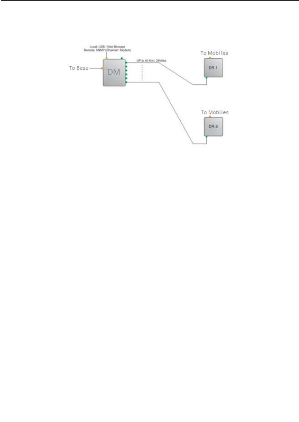
The Fiplex Digital Master is a RF-to-Fiber and Fiber-to-RF conversion system. These conversions are done using
FPGA based Digital Signal Processing. It provides a connection to the Base Station and it centralises all the
connectivity of the DAS. It also provides the possibility to connect up to six Digital Remote Units.
The Digital Remote Unit, also is a RF-to-Fiber and Fiber-to-RF conversion system. These conversions are also
made using FPGA based Digital Signal Processing. It provides amplification to the RF signals needed to provide
signal amplification into the target area.
The Master and Remote Units is where the RF interfaces are located, the Master Unit has the “To Base” RF
Port, and the Remote Unit has the “To Mobile” RF Port.
The advantages of using digital signal transportation over fiber are to avoid the addition of the fiber analog noise
when it is used to transport analog signals. Along with this, the UL squelch of the Digital Remote Unit works not
only per channel but also per time slot, this makes the Fiplex Digital DAS solution unique by its outstanding
management of the UL noise.
The Fiplex Digital Master Unit also provides an access point to monitor and control all the system parameters
not only of the Digital Master Unit but also to each Digital Remote Unit connected on the system. This connection
can be done locally via USB or Web-Browser, or remotely using Ethernet (via SNMP protocol).
The DH4-L series are NFPA Ready orderable with AC or DC option. As optional it can have remote control via
Ethernet or via wireless modem.
The Digital Master Unit and the Digital Remote Units both have heavy duty IP67/NEMA4X cabinet for outdoor
usage, it is designed to be wall or pole mounted, however, to mount on standard 19” rack, a special mounting kit
can be supplied.
For more details refer to the product datasheet.
UM-0840 5
2.1 Digital Master Unit Ports
If the Digital Master Unit is equipped with internal duplexers, the enclosure will only have one
“To Base” RF Port.
If the Digital Master is prepared for custom external duplexers, the enclosure will have two RF
Ports, “Dl In” and “UL Out”.
UM-0840 6
2.2 Digital Remote Unit Ports
If the Digital Remote Unit is equipped with internal duplexers, the enclosure will only have one
“To Mobile” RF Port.
If the Digital Remote Unit is prepared for custom external duplexers, the enclosure will have
two RF Ports, “Dl Out” and “UL In”.
UM-0840 7
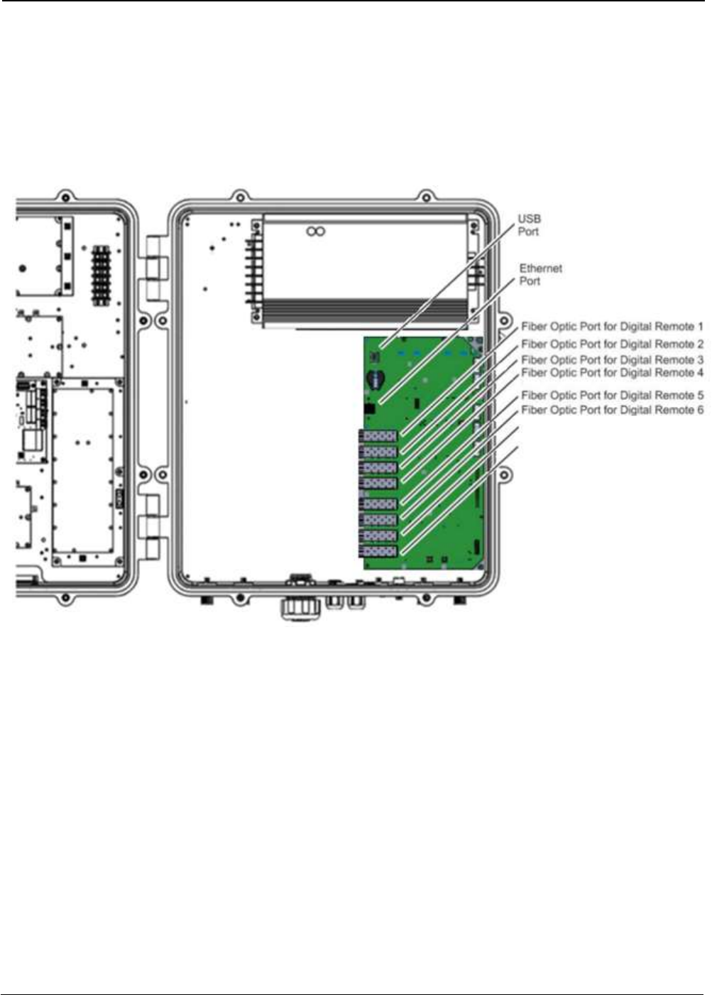
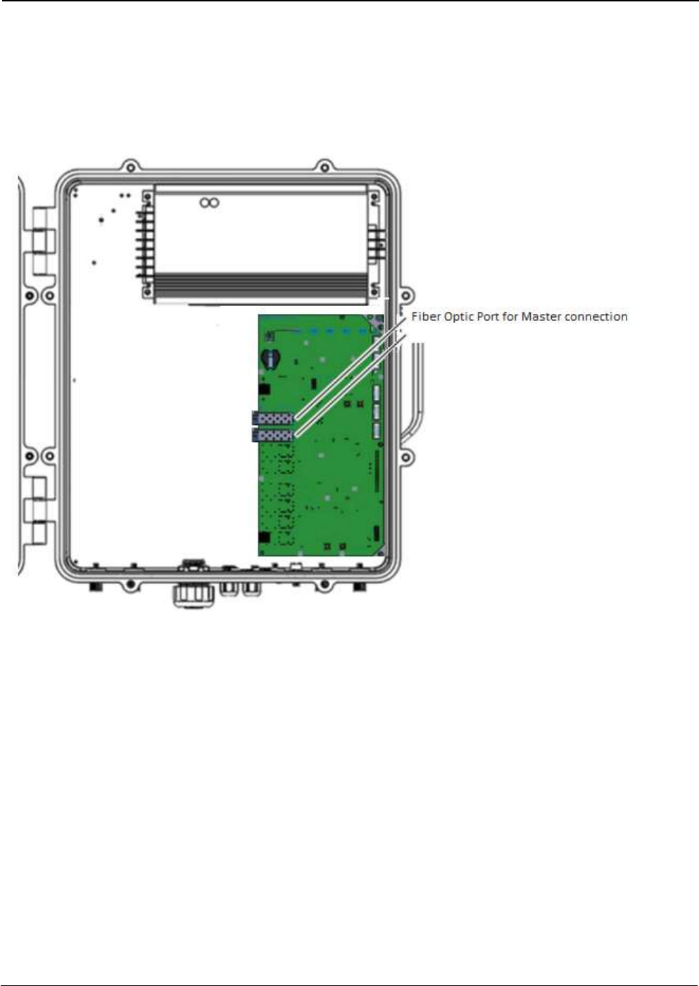
2.3 Connection Diagram
UM-0840 8
2.4 FO Connection
2.4.1 FO Connection in Master Unit
Note: Each fiber connection is performed with simplex fiber and LC-APC connector.
UM-0840 9
2.4.2 FO Connection in Remote Unit
Note: Each fiber connection is performed with simplex fiber and LC-APC connector.
UM-0840 10
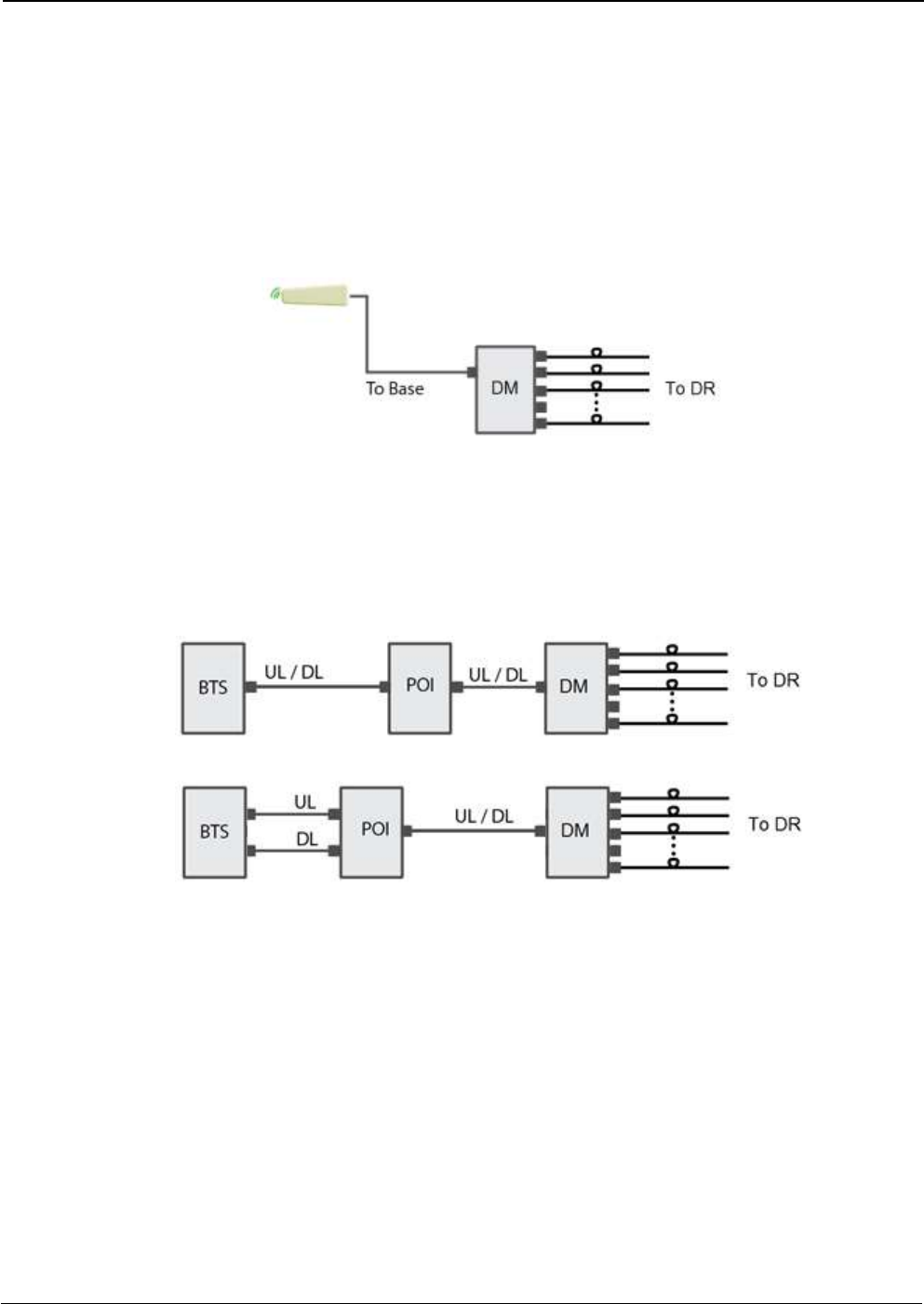
2.5 Interface with signal source
The interface with a Signal Source can be done in three different ways, depending on the availability of separated UL
and DL connectors.
In cases when the signal source will be picked from the air, there is no need to add a Signal Booster to feed the Digital
Master. The Digital Master in its standard configuration can pick the signals from the air just by connecting a donor
antenna to it.
In case when a BTS is used as a Signal Source and the coupling is made thru a Point Of Interconnection (POI). A POI,
can consist on a simple attenuator, duplexer, coupler or a combination of them and it is needed to accommodate the
DL level to the design requested level.
UM-0840 11
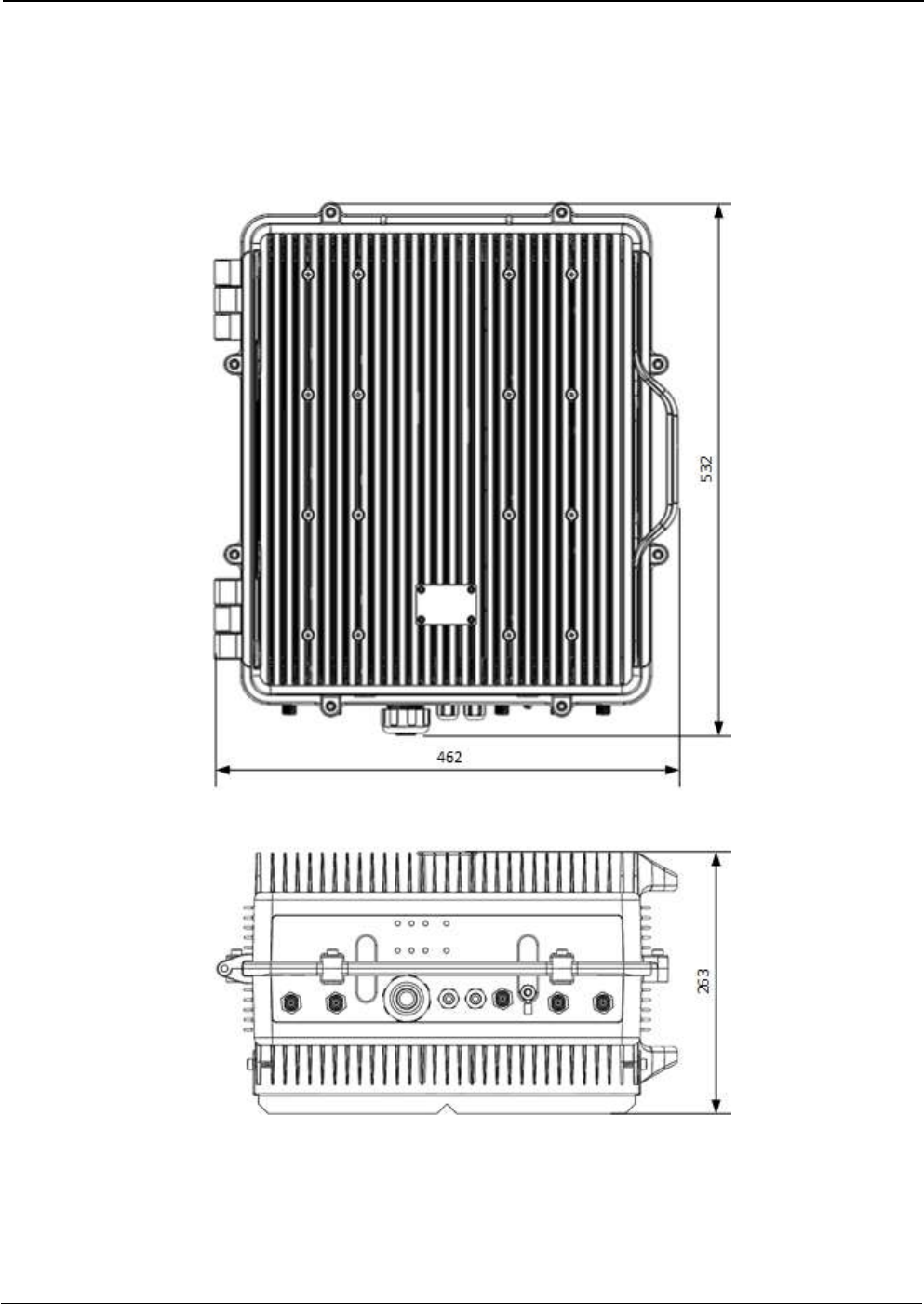
2.6 Dimensions
2.6.1 Digital Master and Remote Unit Cabinet Dimensions
UM-0840 12
3 Installation
Mounting the cabinet
Fiplex Digital Signal Booster is designed for outdoor usage with a weather proof outdoor NEMA4 cabinet that
can be mounted without any kind of shelter from rain, snow or hail.
However, to improve reliability, it is recommended to mount the Digital Signal Booster on a site with shelter
from direct exposure to sun, rain, snow and hailing.
It is not recommended to operate the Signal Booster under bad weather conditions, such as:
- Intense rainfall, snowfall or hail
- Storm or high wind
- Extremely low or high temperature
- High humidity of the air
Mounting
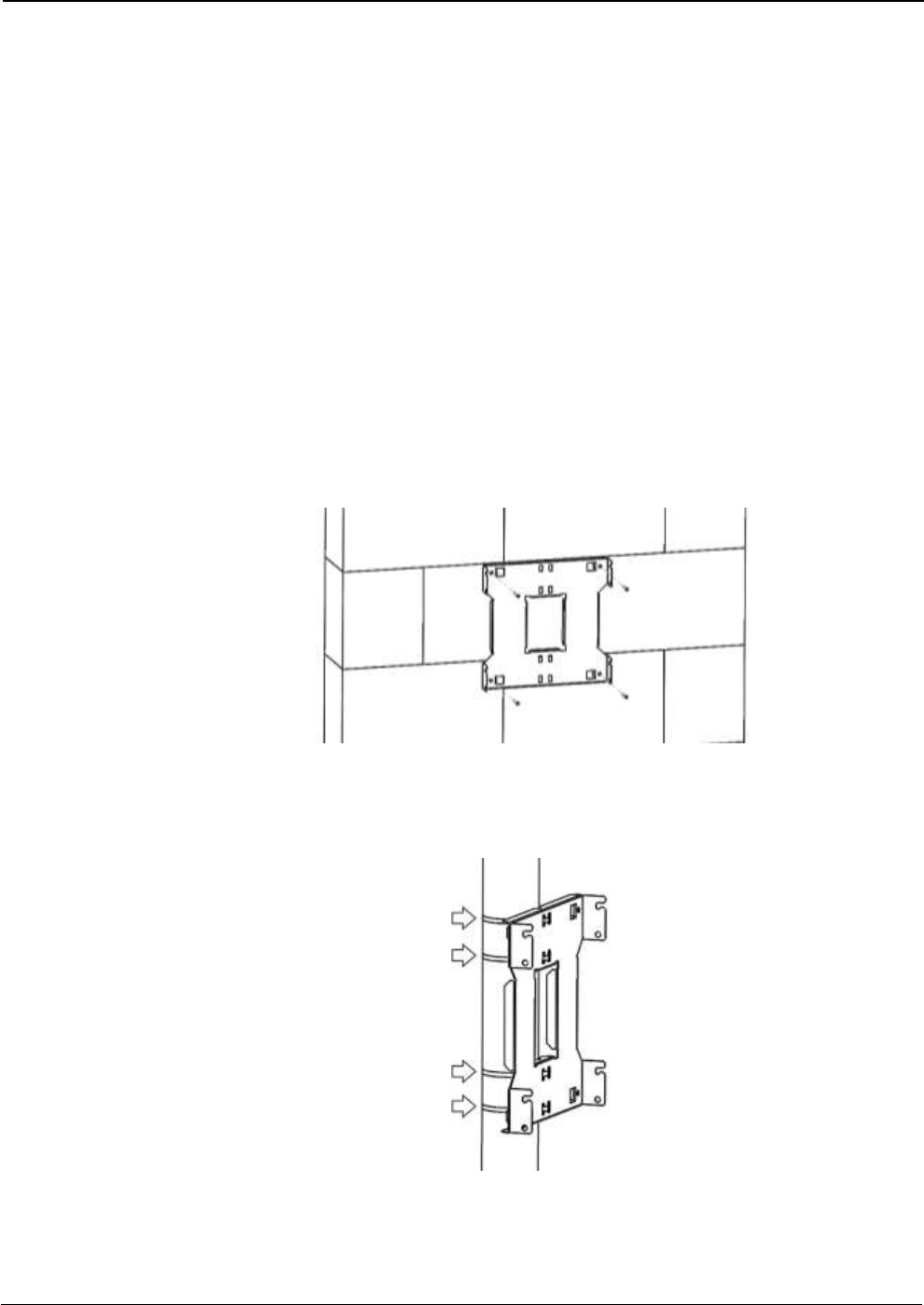
1. Mount the bracket
The Signal Booster can be mounted on a wall or pole. These mounting cases are shown below in Figure 1
and Figure 2. The bracket is provided with the Signal Booster.
Figure 1
Figure 1 shows a bracket attachment to a wall using three fixing screws.
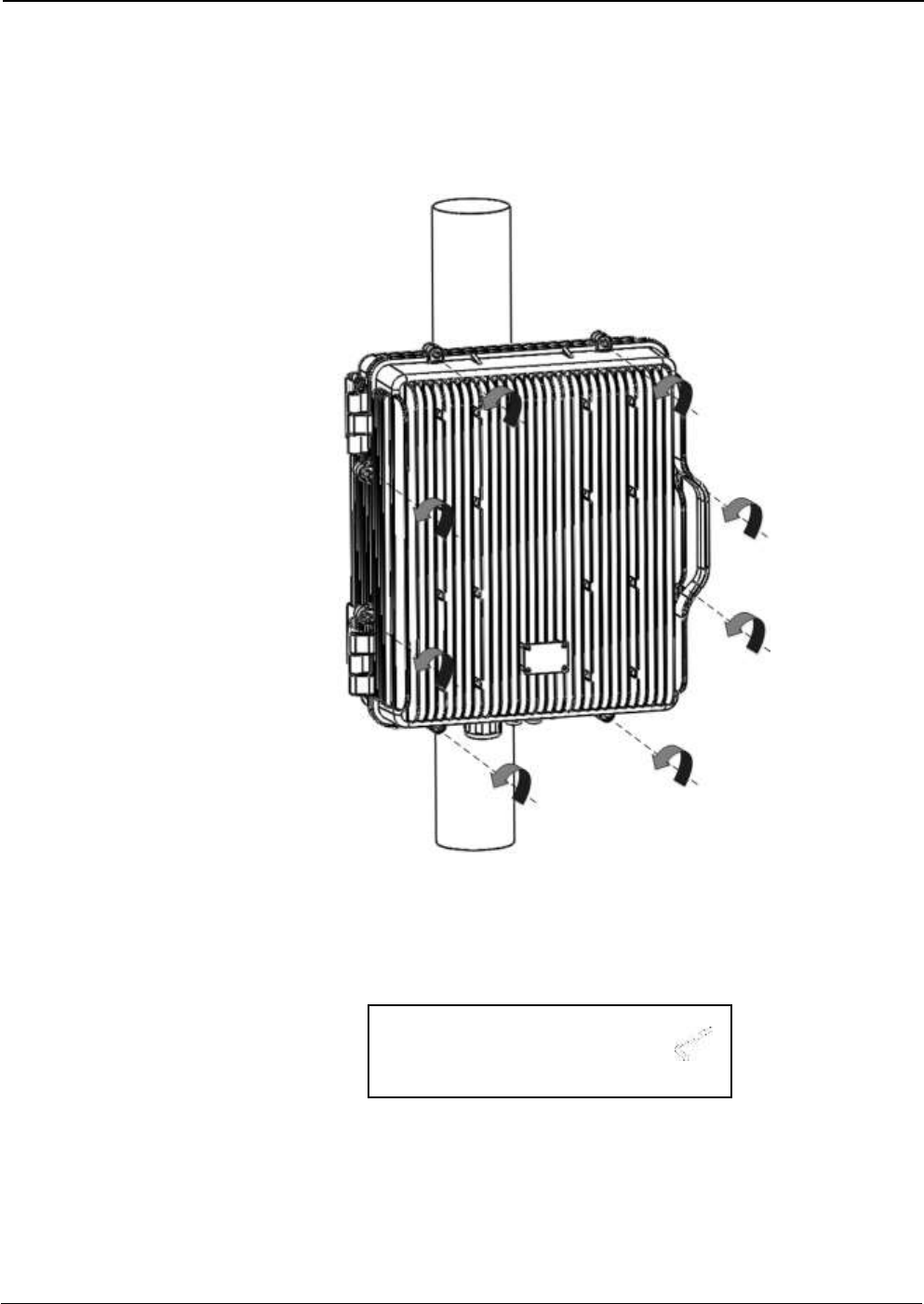
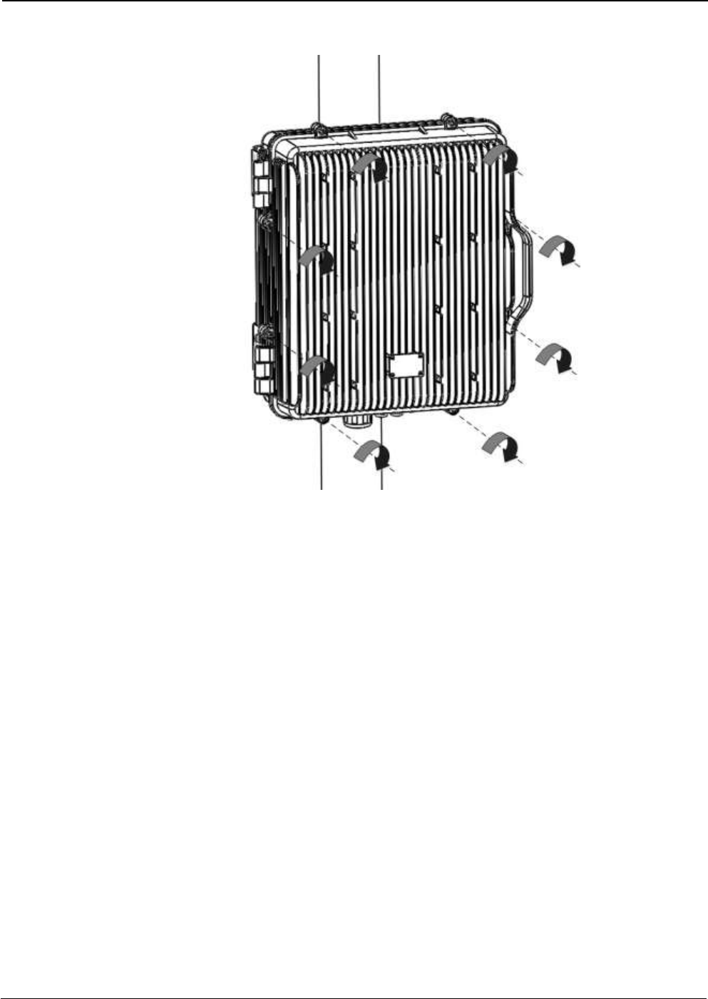
Figure 2
Figure 2 shows a bracket attachment to a pipe using four inox hose clamps (provided with bracket).
UM-0840 13
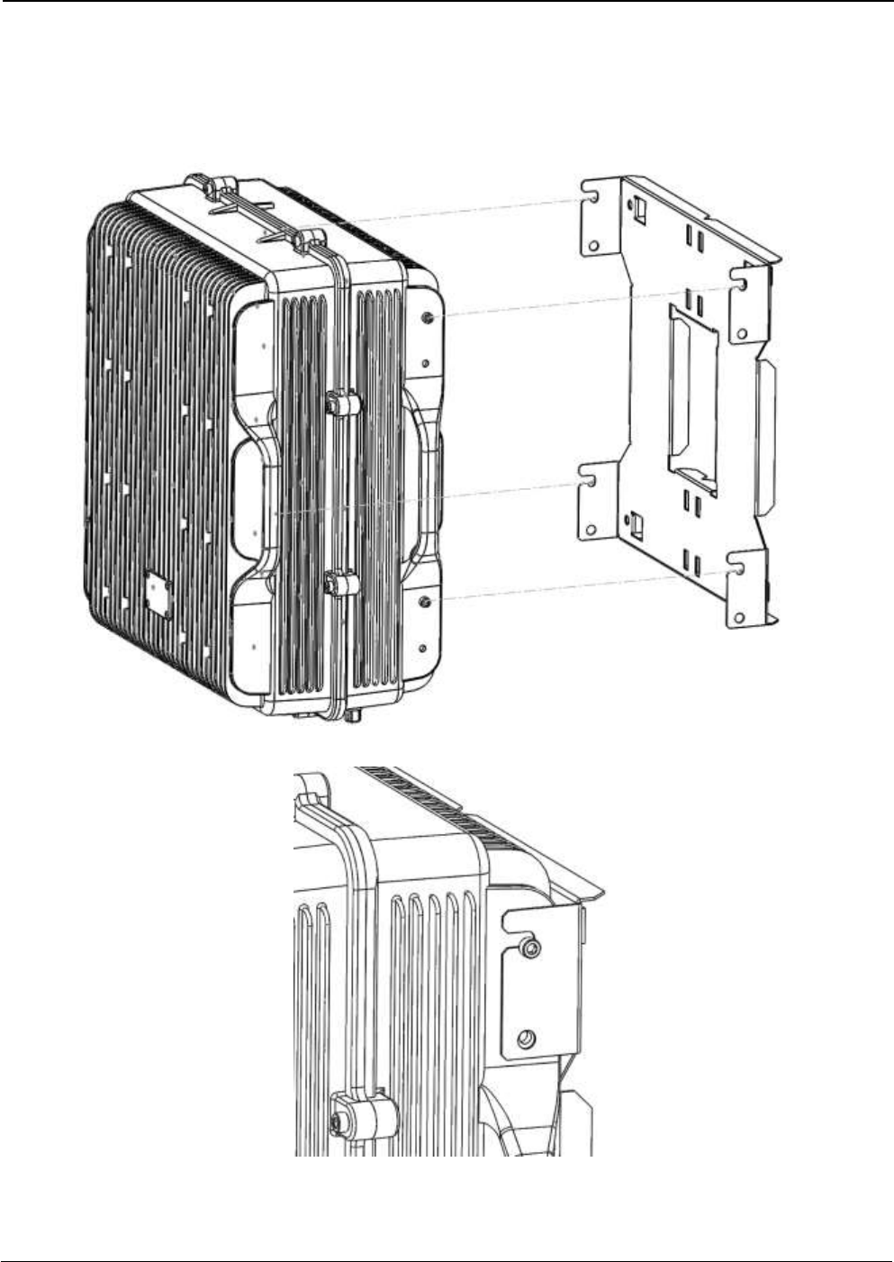
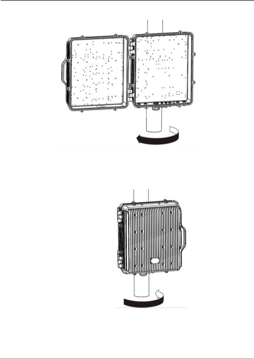
2. After attaching the bracket hang the Signal Booster as shown in Figure 3.
Figure 3
UM-0840 14
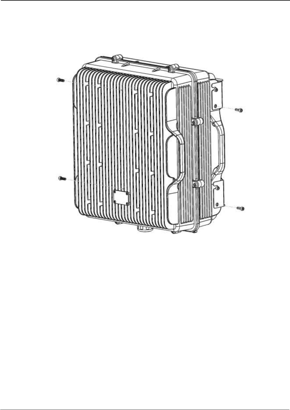
3. Secure the cabinet to the bracket as shown in Figure 4. To attach the Signal Booster’s cabinet to the
bracket use the provided four M6 x 1/2” allen screws.
Figure 4
UM-0840 15
Opening and Closing the Cabinet
To open the cabinet, release the 8 door screws indicated in figure 5 using the provided special
allen key.
A - Release Signal Booster cover.
Figure 5
Use the special allen key N°6
UM-0840 16
B - Open the Signal Booster cover.
Figure 6
C – Close the Signal Booster cover.
Figure 7
UM-0840 17
D - Secure Signal Booster cover.
Figure 8
UM-0840 18
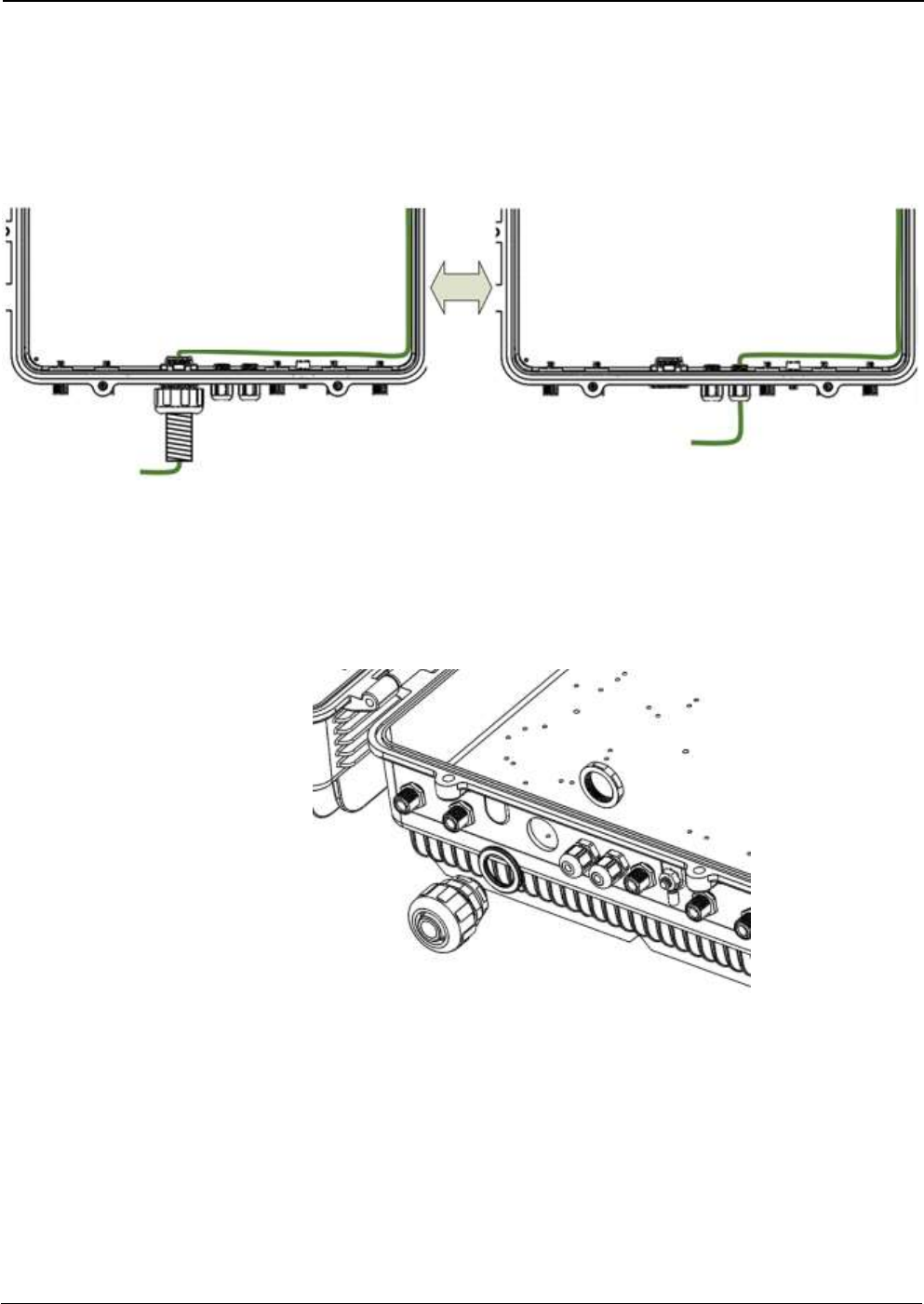
Use of Liquid Tight Conduit
The unit has available a Liquid Tight Conduit Fitting connector. The unit as standard has the
connector installed, so if the user requires to use this connector, if available, the NFPA cables,
Ethernet, DC and AC cables can be routed through this connector.
Figure 9; AC Routing through cable gland or conduit connector
If the is not going to use Liquid Tight Conduits, then the connector should be replaced by the
provided sealing cup as indicated in Figure 10.
A - Remove the conduit connector
UM-0840 19
B – Install the sealing cup
Figure 10; Replacement of Conduit connector to sealing cup
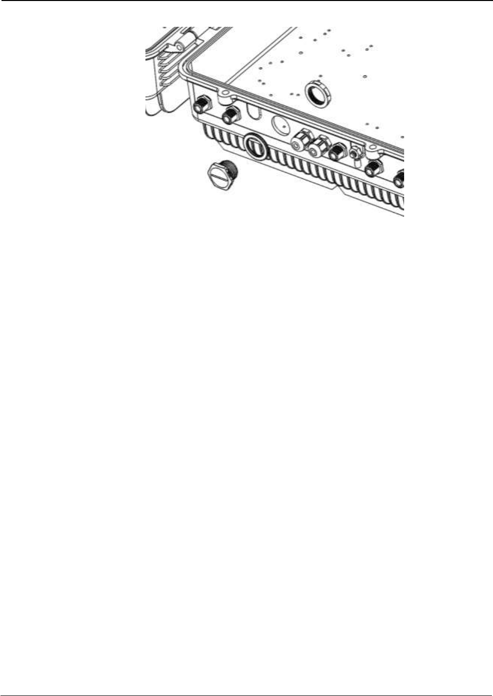
Nema4X considerations
This device is equipped with a Nema4X enclosure, however, to ensure the Nema rating,
the user must have the following considerations:
1. Correct use of the Liquid Tight Conduit. In case this interface is not used, it should
be replaced with the sealing cup.
2. Sealing cups should be installed in the non-used cable glands.
3. The RF Ports should be perfectly mated.

UM-0840 20
4 Commissioning
4.1 Connection step by step
Connect the RF ports, Power, Fibers and Ethernet Cable Glands location, for Master and Remote units
following the next steps:
1. For Master Unit:
a. Master Unit with internal duplexers
i. Connect the signal coupled from the base station to the “To Base” RF port. N type
female connectors are used in the unit. The coupling to Base station can be done
with a Donor antenna or through a POI.
ii. Connect fiber cables to internal optical modules. LC-APC connectors are used in the
unit. Connect the remote units on the dedicated ports.
iii. Connect USB Cable for local management.
b. Master Unit with external duplexers
i. Connect the signal coming though the external duplexer using the “UL Out” and “DL
in” RF ports. N type female connectors are used in the unit.
ii. Connect fiber cables to internal optical modules. LC-APC connectors are used in the
unit. Connect the remote units on the dedicated ports.
iii. Connect USB Cable for local management.
2. For Remote Unit:
a. Remote Unit with internal duplexers
i. Connect service antenna (“RF To Mobile” port) coaxial cable to remote unit. N type
female connectors are used in the unit.
ii. Connect fiber cable to internal optical module. LC-APC connector is used in the unit.
b. Remote Unit with external duplexers
i. Connect the remote unit to the externa duplexer using the “DL Out” and “UL In” RF
Ports. N type female connectors are used in the unit.
ii. Connect fiber cable to internal optical module. LC-APC connector is used in the unit.
3. Once RF ports of the unit are properly loaded connect the Main Power the AC or DC source depending
on the model.
If using the AC model, electrical installation must provide differential and thermo-magnetic breaker
elements according to electric safety international regulations.
If using the DC model, the Main Power cable provided with the unit has tree poles:
- The Green cable is connected to the chassis.
- The Blue cable should be connected to the most positive source tension.
- The Brown cable should be connected to the most negative source tension.
For -48VDC supply voltage, connect the 0V(GND) reference to the Green and Blue cable, and the -48VDC
to the Brown cable.
For +48VDC supply voltage, connect the 0V(GND) reference to the Green and Brown cable, and the
+48VDC to the Blue cable.
UM-0840 21
L N
TMB
DB
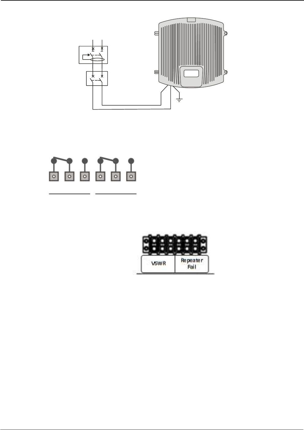
4. If the Remote Unit has the NFPA Option, there is a dedicated cable gland for this purpose. A multi-
conductor cable can be used to connect the NFPA dry contacts to the Fire Department Control Box.
Figure 11; NFPA Dry Contact connection configuration
Figure 12; NFPA Dry Contact connection location inside the cabinet
5. Once the unit has been connected to the power source, it takes about 30 seconds to run a booting
routine. After that time unit is ready to be connected via USB cable to the Digital Master to a computer
running Fiplex Control Software (FCS) in order to be properly configured.
456123
NC NO NC NO
Repeater
Fail
VSWR
Status of contacts (Alarms Off)
Pin 1 – 2 = VSWR (normally closed contact)
Pin 2 – 3 = VSWR (normally open contact)
Pin 4 – 5 = Repeater Fail (normally closed contact)
Pin 5 – 6 = Repeater Fail (normally open contact)
UM-0840 22
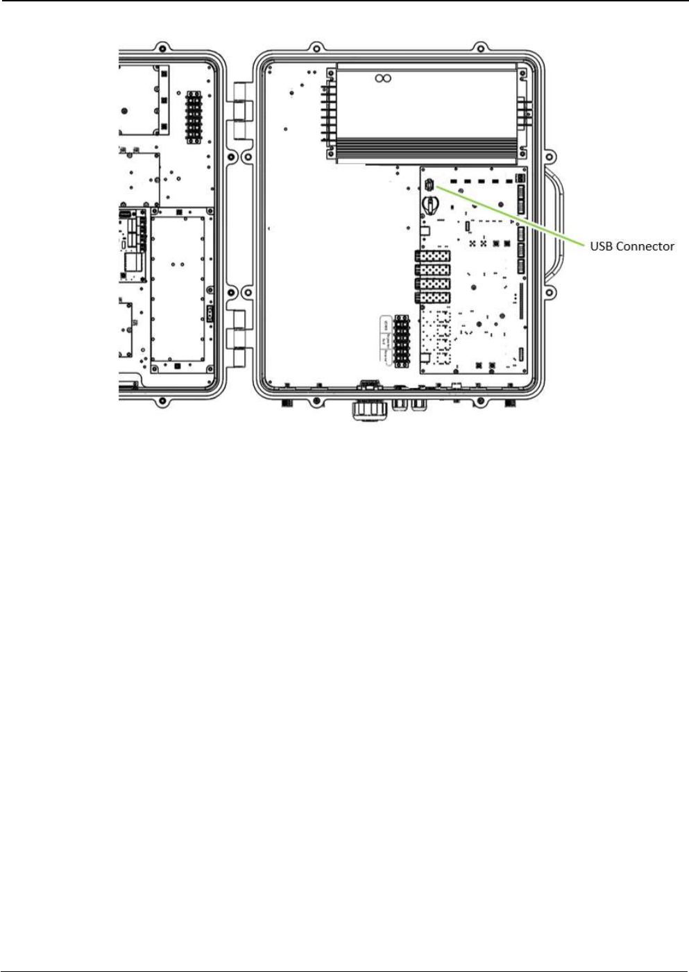
Figure 13; USB Port location inside the cabinet
UM-0840 23
4.2 Starting Operation
BE SURE THAT “TO MOBILE” AND “TO BASE” PORTS ARE PROPERLY
LOADED EITHER WITH 50 OHMS DUMMY LOADS, OR RADIATING SYSTEM.
1. Turn on the repeater, connect computer to repeater through USB cable, and run Fiplex Control
Software. Check that all remote units are connected to the master through fiber optic checking link
status.
2. Enable channel filtering if needed and setup desired channel frequencies. If Fiplex Digital Fiber DAS is
used as channel selective, user has to know what frequencies are used in base station. Each channel
can be enabled independently. Channels not used can be showed / hidden using the “Show channels”
checkboxes. If remote units are on and connected through optical fiber, the corresponding uplink
frequencies will be automatically set, too.
Link status
UM-0840 24
3. According to DL RF input levels, program input attenuator to avoid input overflow, and output
attenuator for each remote to obtain desired output level in each remote.
4. Reciprocally, set UL band gain adjusting output attenuator of master unit. It is recommended that DL
gain and UL gain be equal.
Set number of active channels and frequencies
Set Input attenuator
Set Output attenuator
UM-0840 25
5. Set up squelch settings. Controls are independent in UL (for each remote) and DL (master) bands.
Typical values for UL are between -110dBm and -100dBm for squelch threshold. For DL,
recommended value for squelch threshold is minimum level received in any active channel minus
10dB.
6. Setup desired filter bandwidth, depending on presence of adjacent channels. In principle,
recommended bandwidth filter is 90KHz due to its low delay, but if adjacent signal is detected, narrow
filters can be used. Fine gain can be set to equalize input signals.
Set Output attenuator
Check UL and DL gain for each remote
DL squelch settings
UL squelch settings
UM-0840 26
Filters and fine gain settings
UM-0840 27
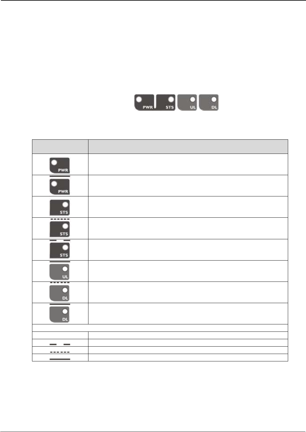
4.3 Status Indicators
There is an indicator panel located at the front panel of the repeater. This led panel works as a
status monitor, in order indicate warning or alarms of repeater
There are four leds, first one the power ON indication led, labelled “PWR”.
A Second led, labelled “STS” summarizes warnings regarding critical operational conditions of
the repeater.
Third and fourth led summarizes operational conditions for uplink “UL” and downlink “DL” chains.
In general, leds has four states: off, slow blinking, fast blinking, on. Table 1 describes alarm and
warning conditions for each led state in the master device and Table 2 is for remote devices.
Table 1
Indicator Panel
LED indication description
Unit is not powered or fail in power supply
Normal state: Unit is powered on
Normal state
HW fail: digital signal processor is not detected
Temperature: very high internal unit temperature
Optical fiber alarm in at least one link
TBS Warning: No signal is detected coming from base station
Normal state
RF input overflow: maximum level at RF input is exceeded
Normal state
Where:
Led OFF
Led slow blinking with period of 2 seconds aprox. WARNING
Led fast blinking with period of 0.5 seconds aprox. ALARM
Led ON
UM-0840 28
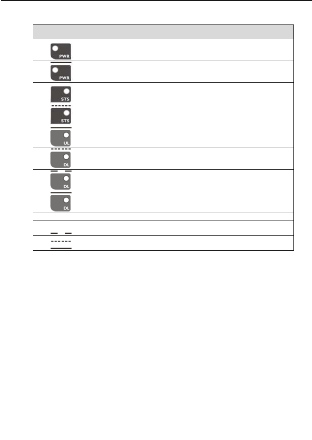
Table 2
Indicator Panel
LED indication description
Unit is not powered or fail in power supply
Normal state: Unit is powered on
Normal state
HW fail: digital signal processor is not detected
Temperature: very high internal Unit temperature
Optical fiber alarm in at least one link
Normal state
PA Overflow or excessive temperature alarm.
PA Underflow: PA output level is lower than +25dBm
Normal state
Where:
Led OFF
Led slow blinking with period of 2 seconds aprox. WARNING
Led fast blinking with period of 0.5 seconds aprox. ALARM
Led ON
4.4 Laboratory Measurements
For specific parameters verification and laboratory tests, please contact factory.
Detailed procedures, recommended tests set up, and a knowledge engineering team will bring adequate
support to perform this measurements in a comfortable and safely way.
UM-0840 29
Part 2 SOFTWARE
5 Introduction
Fiplex Fiber DAS can be fully configured and monitored through USB connection. Digital Master
unit receives through optical links monitoring and configuration data from remotes units. For this
reason, whole system can be fully configured and supervised from digital master unit.
6 USB Software
6.1 Software description (Digital Master)
If software has been successfully installed and connected to Digital Master (see section 7) status
screen will appear. In this screen, RF configurations parameters (channel frequencies, bandwidth
filter, gains / attenuation) and RF and optical links monitoring (RF input/output levels, AGC status,
optical link status) are shown.
At left side of webpage, configuration menus are shown:
Content
Status: whole RF configuration and monitoring parameters are shown. These
parameters are described in next section.
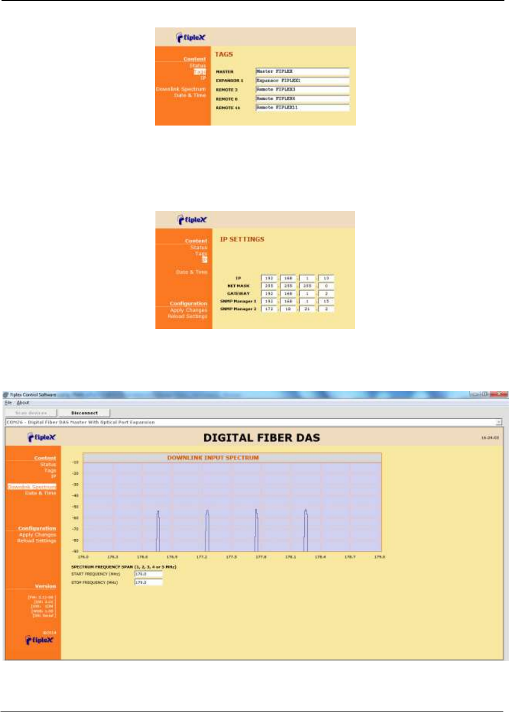
Tag: user can set a tag to ease repeater identification. For modifying the TAG, write
a new value in text field and click over Apply Changes link
UM-0840 30
IP: At this page (for units with Ethernet supervision), IP addresses configuration and
addresses of SNMP Managers are shown. User can set addresses of two SNMP
Managers (IP where SNMP agent will send TRAP information). To modify, click over
Apply Changes link after writing new values on text fields. Also router 3G IP address
can be viewed in this screen (if 3G router option is installed)
Downlink Spectrum: in order to know input signal: level of desired channels,
unwanted channel levels, Digital Master provides an spectrum analyzer that shows
input signal in frequency domain.
Date & Time (for units with Ethernet supervision): page to modify real time clock.
When the repeater is not powered, this clock runs with a voltage supply provided by
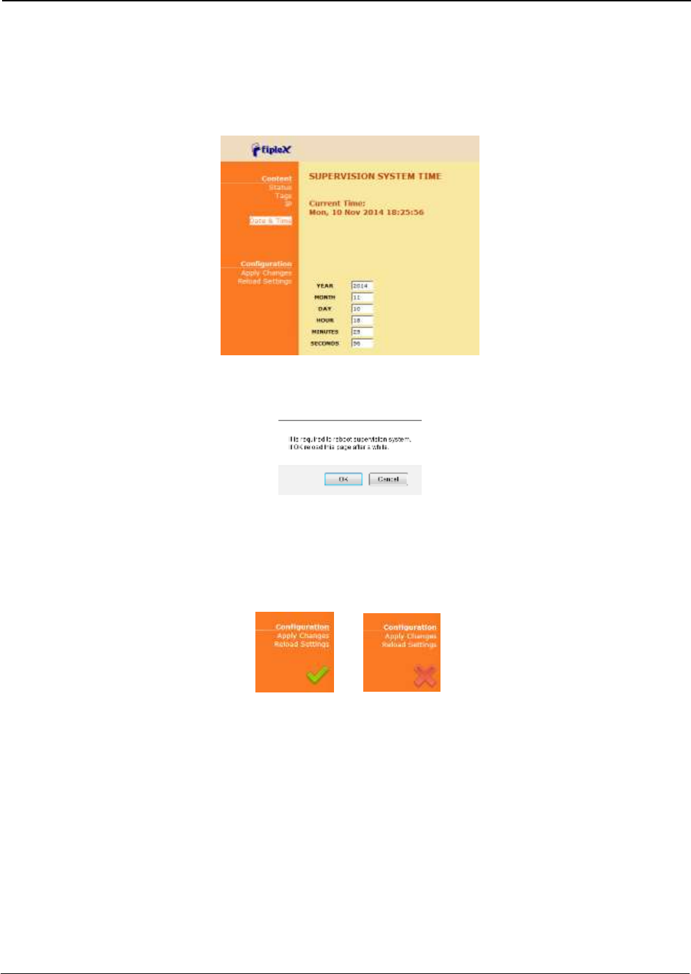
UM-0840 31
a 3V lithium battery, button type of 20mm (CR2032) with 220mA·h. This suffices for
at least half year. When the repeater is powered, no current is drained from the
battery. So, actual battery life will depend on repeater usage. For battery
replacement, please locate battery holder between USB and Ethernet connectors on
main board. Battery positive side is UP, i.e. on holder clip.
After clicking on “Apply Changes” link, next message will appear, warning the user that
system needs to be rebooted.
Configuration
o Apply Changes: as it is said above, this link is used to load changes to the
repeater, in configuration, tag, IP, password and date and time menus. After
any configuration change, web page will show and icon that allows user to
know if configuration has been successfully applied:
o Reload Settings: clicking this link, repeater configuration data is refreshed.
Version: shows hardware, firmware and software versions of repeater and serial
number.
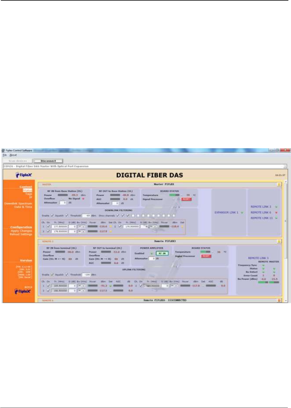
6.2 RF parameters description (Digital Master)
“Status” menu shows whole RF configuration and RF and optical links monitoring data that are
distributed along the webpage.
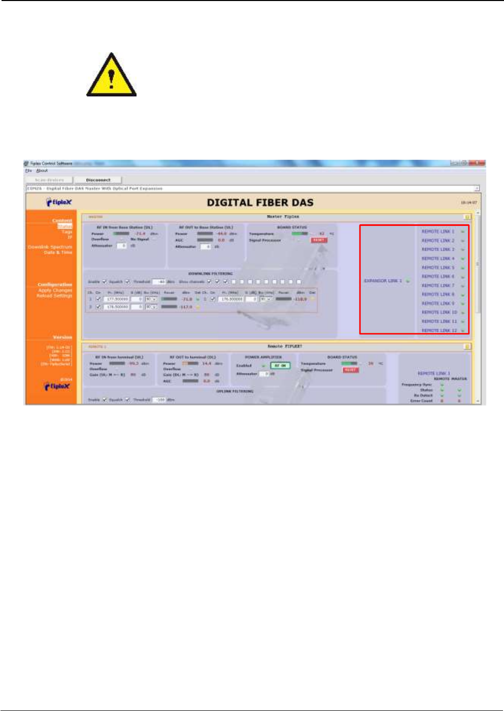
The first frame called “MASTER” is placed in top of webpage, showing configuration of digital
master unit. Below this, some frames titled “REMOTE 1”, “REMOTE 2”... . There is one for each
remote unit connected to the master, and configuration and status information related to each
remote can be viewed. Next figures show these frames:
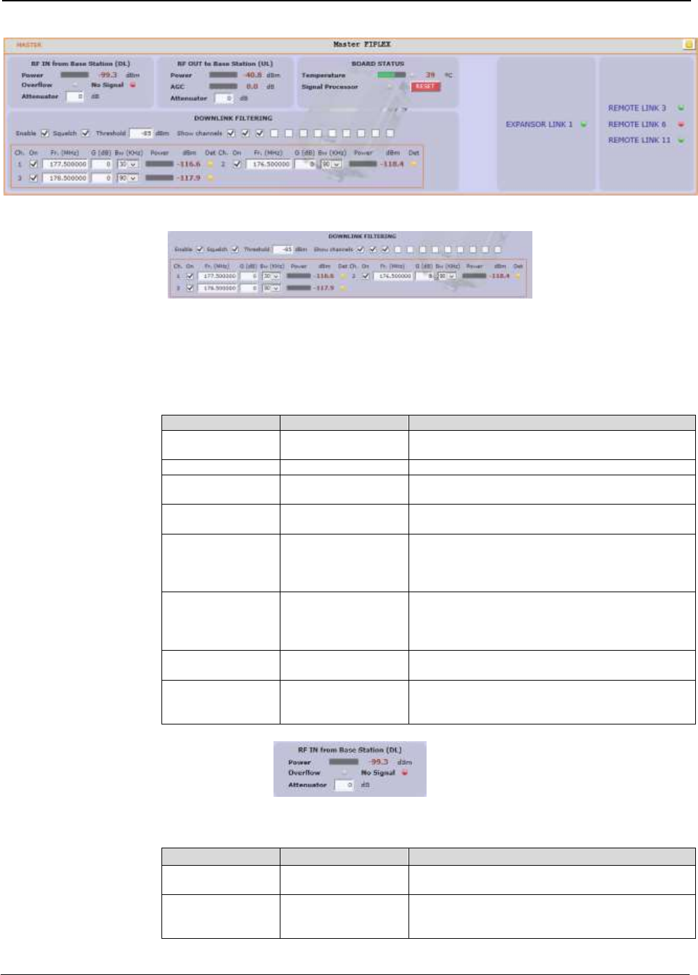
UM-0840 32
Digital Master frame. There are five sub-sections inside this frame:
o Downlink filtering: this section contains fields to modify channel frequencies,
squelch options and filtering options. Parameters are described in following
table:
Parameter
Range
Description
Frequency
Downlink band
Downlink frequency channels. Frequency
resolution is 3.125KHz
Channel enable
Enabled / disabled
Each of 12 channels can be enabled/disabled
Bw Filter
90KHz / 45KHz /
30KHz
Bandwidth of channels filter can be
independently adjusted (if filtering is enabled)
Fine Gain Adjust
-5 to +5dB
If filtering is enabled, gain of each channel can
be fine adjusted
Power indicator
---
Level of each channel, measured according to
its bandwidth filter, is shown in dBm units. Led
indicator shows if levels exceeds squelch
threshold (green) or not (yellow).
Squelch enable
control
Enabled / disabled
Enabling this control, repeater does not transmit
in each channel if RF input power do not exceed
the threshold level configured according to next
row
Squelch threshold
control
-90dBm to 40dBm
If squelch is enabled, input levels below this
threshold are not transmitted.
Filtering enable
Enabled / disabled
Filtering option can be bypassed. If filtering is
disabled, fine gain adjustments and squelch
options are ignored
o Master RF Input parameters. Next table describes information of this frame:
Parameter
Range
Description
Broad band level
---
This indicator shows input level measured along
DL band
Overflow
Grey: normal state /
Red: alarm state
This indicator shows overflow on input circuitry is
occurring. This condition can be avoided
increasing input attenuator
UM-0840 33
Input Attenuator -
RF IN from TBS
(DL)
0dB to 30dB
Input attenuator to accommodate input levels.
This value must be set to avoid overflow
condition. Together with output attenuator of
remotes sets the downlink gain:
G_DL (dB) = 80 – AttINmaster(dB) –
AttOUTremote(dB)
o Master RF Output parameters. Next table describes information of this frame:
Parameter
Range
Description
UL Output power
---
This indicator shows output level in UL band
AGC
Grey: normal state /
Red: alarm state
This indicator shows gain reduction that master
unit is applying at RF output to prevent PA UL
overload
Output Attenuator
RF OUT to Base
Station (UL)
0dB to 30dB
Output attenuator to adjust UL gain. System UL
gain can be computed as:
G_UL (dB) = 80 – AttOUTmaster(dB)
o Master Board status: general parameters of master unit are contained in this
frame
Parameter
Range
Description
Temperature
---
This indicator shows unit temperature
High temperature
alarm
Grey: normal state /
Red: alarm state
High temperature alarm condition is indicated
with this led.
Signal processor
alarm
Grey: normal state /
Red: alarm state
Alarm indicates that digital signal processor is
not working properly.
RESET control
---
With this control, unit can be restarted
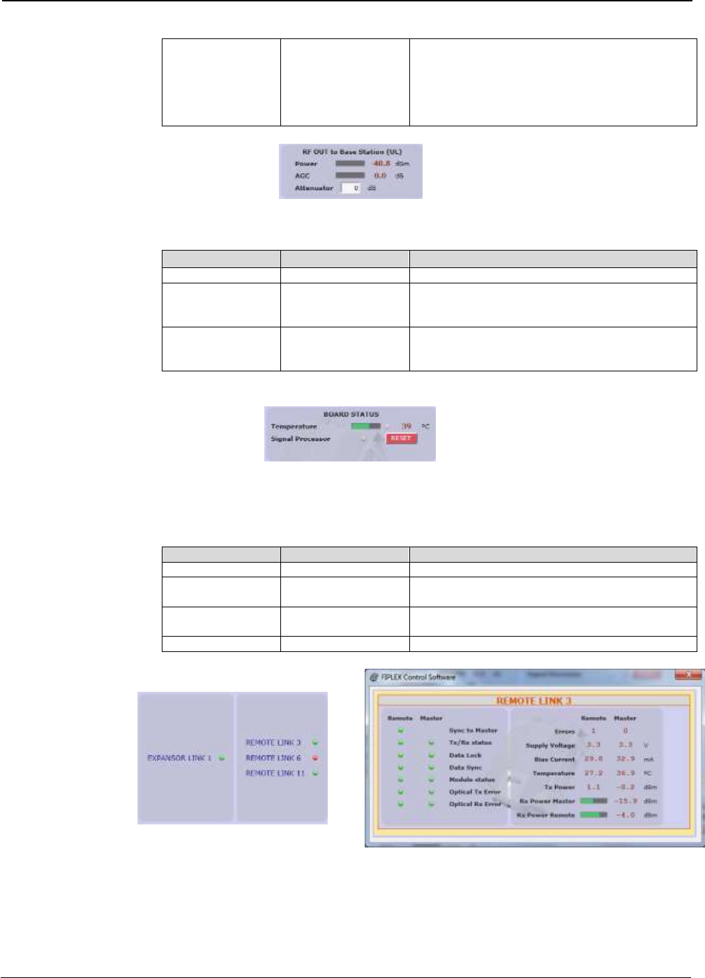
o Optical link status: each indicator shows optical link status between digital
master and each remote unit. Clicking on “REMOTE LINK n” detailed monitoring
data of each optical link can be viewed: voltage, current and temperature of
UM-0840 34
each optical module, transmitted and received optical power, and alarms related
to digital data recovery system.
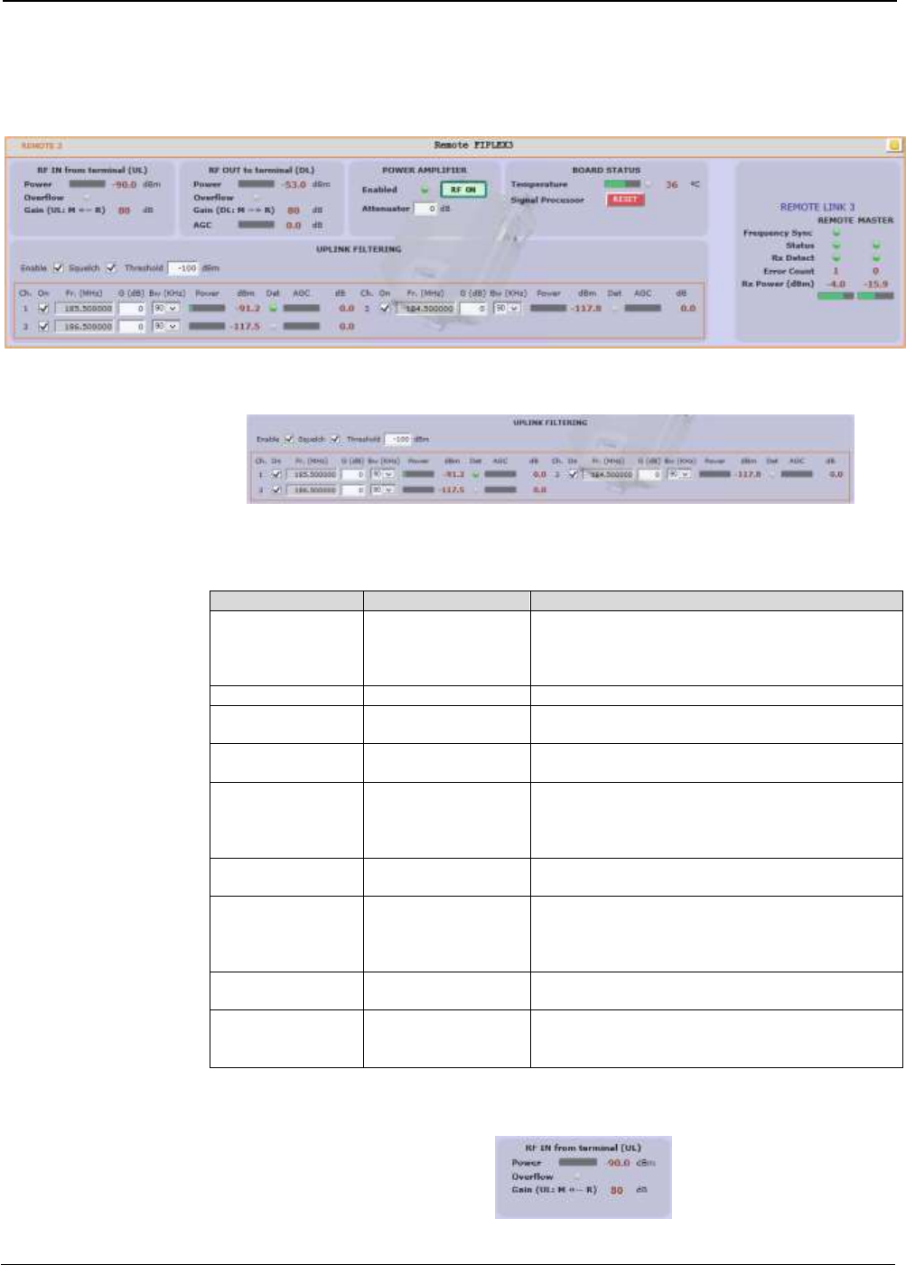
Remote frame: shows configuration and monitoring information of each remote unit. The
frame is divided in the following sections:
o Uplink filtering: this section shows equivalent parameters of downlink filtering of
master unit.
Parameter
Range
Description
Frequency
UL band
Uplink frequency channels. These frequencies
are derived automatically from downlink
frequencies, taking into account frequency
separation between DL and UL bands
Channel enable
Enabled / disabled
Each of 12 channels can be enabled/disabled
Bw Filter
90KHz / 45KHz /
30KHz
Bandwidth of channels filter can be
independently adjusted (if filtering is enabled)
Fine Gain Adjust
-5 to +5dB
If filtering is enabled, gain of each channel can
be fine adjusted
Power indicator
---
Level of each channel, measured according to
its bandwidth filter, is shown in dBm units. Led
indicator shows if levels exceeds squelch
threshold (green) or not (yellow).
AGC
---
Show gain reduction to prevent overloading in
AGC per channel
Squelch enable
control
Enabled / disabled
Enabling this control, repeater does not transmit
in each channel if RF input power do not exceed
the threshold level configured according to next
row
Squelch threshold
control
-110dBm to -70dBm
If squelch is enabled, input levels below this
threshold are not transmitted.
Filtering enable
Enabled / disabled
Filtering option can be bypassed. If filtering is
disabled, fine gain adjustments and squelch
options are ignored
UM-0840 35
o Remote RF Input parameters. Next table describes information of this frame:
Parameter
Range
Description
Broad band level
---
This indicator shows input level measured in UL
band
Overflow
Grey: normal state /
Red: alarm state
This indicator shows overflow on input circuitry is
occurring.
Uplink gain from
remote to master
--
Shows system uplink gain for each remote. Can
be calculated as:
G_UL (dB) = 80 – AttOutMaster(dB)
o Remote RF Output parameters. Next table describes information of this frame:
Parameter
Range
Description
Output power
level
---
This indicator shows the PA output power
PA Overflow
Grey: normal state /
Red: alarm state
Indicates that PA is overloaded. Condition is
output power higher than +43dBm
Downlink gain
from master to
remote
---
Shows downlink gain for each remote. Can be
calculated as:
G_DL (dB) = 80 – AttInMaster(dB) –
AttOutRemote(dB)
AGC
---
Shows gainr reduction applied in DL band signal
to prevent PA overload
o RF on/off control and Board Status:
Parameter
Range
Description
RF on/off
Indicator
Green: RF Enabled
/ Red: RF Disabled
This indicator shows PA status. Power amplifier
can be automatically disabled if other alarm
conditions occurs:
a) Fail in optical link
b) PA Overflow
RF Enable Control
On / Off
With this control RF DL and UL chains can be
disabled
Output attenuator
0 to 40dB
This control sets the output attenuation used to
set DL gain together with Master Input
Attenuator
Temperature
---
This indicator shows unit temperature
High temperature
alarm
Grey: normal state /
Red: alarm state
High temperature alarm condition is indicated
with this led.
RESET control
---
With this control, unit can be restarted
UM-0840 36
o Optical link status: shows optical link status between master and each remote
unit. Moreover, clicking on “REMOTE LINK n” detailed monitoring data of each
optical link can be viewed: voltage, current and temperature of each optical
module, transmitted and received optical power, and alarms related to digital
data recovery system. The main window shows only general parameters:
Parameter
Range
Description
Frequency Sync
Green: Normal state /
Red: Alarm state
This indicator shows frequency
synchronization status between master and
remote unit
Status
Green: Normal state
Yellow: Warning state
Red: Alarm state
This indicator summarizes the status of optical
module based in voltage, current, temperature
and optical transmitted power
Rx Detect
Green: Normal state
Yellow: Warning state
Red: Alarm state
This indicator summarizes the status of optical
reception based in received optical power and
digital data recovery system
Error Count
---
Counter that it is incremented when optical link
fails.
Rx Power
---
Shows optical received power. For reliable
optical link, RX power must be higher than
-25dBm
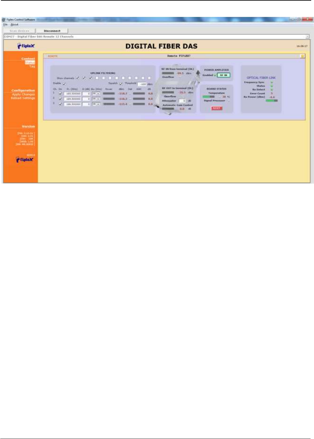
6.3 Software description (Remote Unit)
While software connected to digital master allows configuration and monitoring of whole system, if
software is connected to remote unit, only parameters of this unit can be viewed / modified.
Then, status screen of remote unit only shows information regarding this unit:
UM-0840 37
Distribution and meaning of the controls contained in status page are very similar to single remote
frame of master status page, only optical frame is different due to only remote side of optical link is
monitored.
7 Local Software. Installation and troubleshooting
7.1 Installation
The following section will describe the steps to be followed in order to install and use the Fiplex
Control software with your Fiplex repeater.
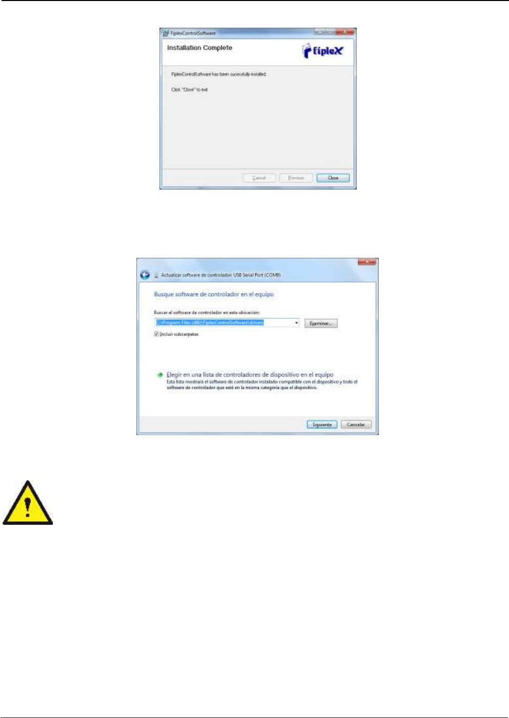
1. Before connect USB cable between computer and repeater, run the
FiplexControlSoftware.msi File. Next screen will appear…
UM-0840 38
2. Choose the default installation path “C:\Program Files (x86)\FiplexControlSoftware”. Note that this
can change according to your system configuration (32bits or 64bits), language and Windows
Version.
3. The installer will start to copy the necessary files.
4. After installation has completed, a shortcut in user desktop will appear.
UM-0840 39
5. Connect USB cable between computer and repeater, keeping the repeater powered off.
Usually, drivers will be automatically installed, but depending on Windows version, screen
asking for drivers of new device can appear. Drivers can be found in application folder:
C:\Program Files (x86)\FiplexControlSoftware\drivers”.
6. Turn on the Repeater
BE SURE THAT “TO MOBILE” AND “TO BASE” PORTS ARE PROPERLY
LOADED EITHER WITH 50 OHMS DUMMY LOADS, OR RADIATING SYSTEM.
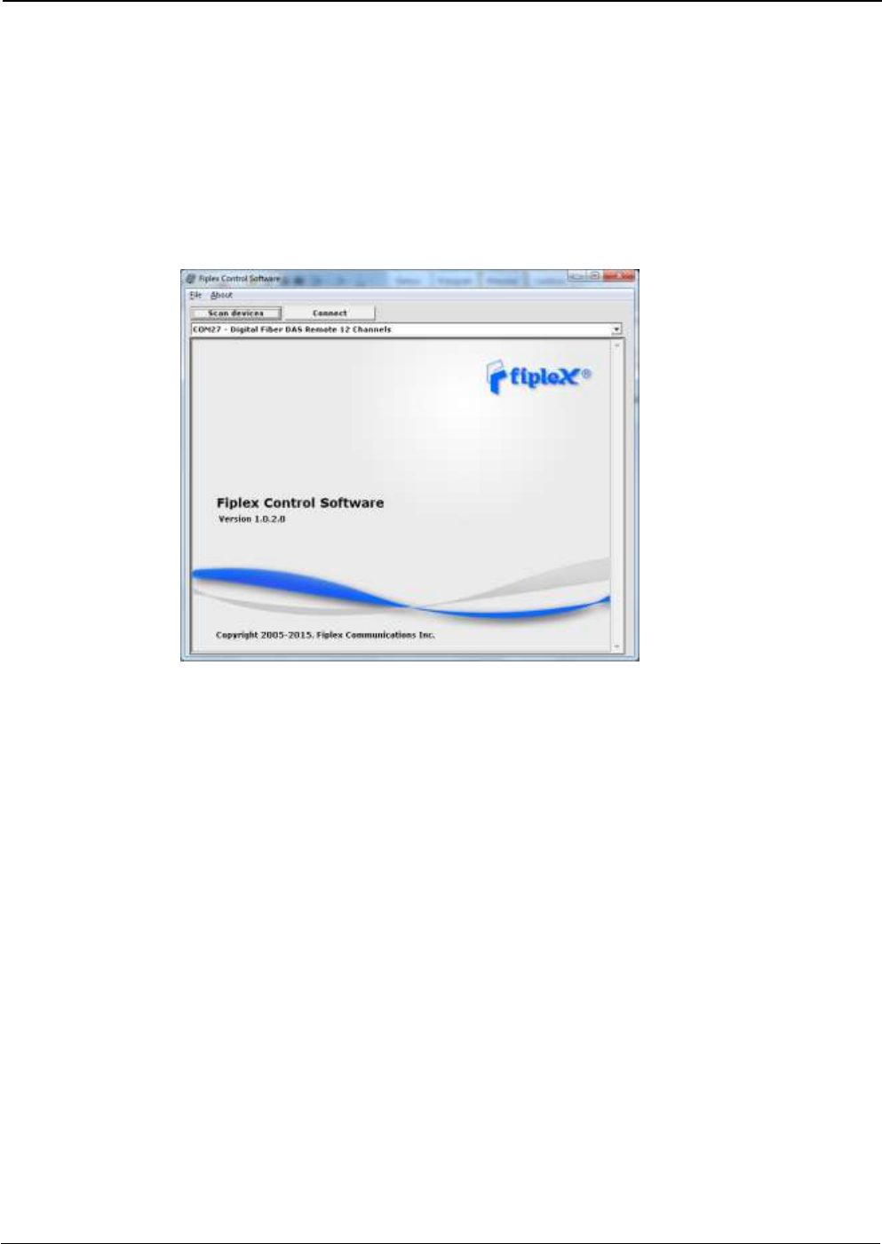
7. Execute the Fiplex Control Software. Next window will appear:
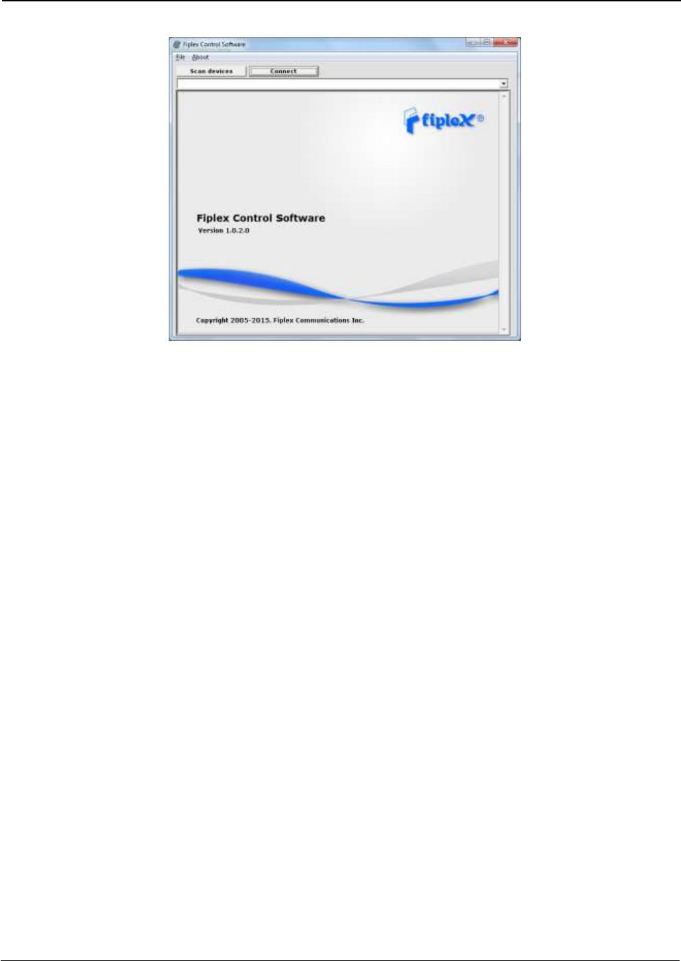
UM-0840 40
User interface has the following controls:
Scan Devices Button: refresh the available COM ports and identify Fiplex devices
Connection Button: connect / disconnect software from repeater
List of available devices: below two buttons, is placed a dropdown list that shows all
available COM ports. Available COM ports not related to Fiplex devices will be shown
with its number and “Unknown device” label. COM ports related to Fiplex devices will
show a device description.
Embedded Web browser: graphical area where configuration and monitoring parameters
will be shown.
File menu: contains menus to save repeater configuration to a file and load configuration
from file to repeater.
NOTE: if Fiplex Repeater is not turned on, related COM port will appear as “Unknown
device”
8. Click “Scan Devices”
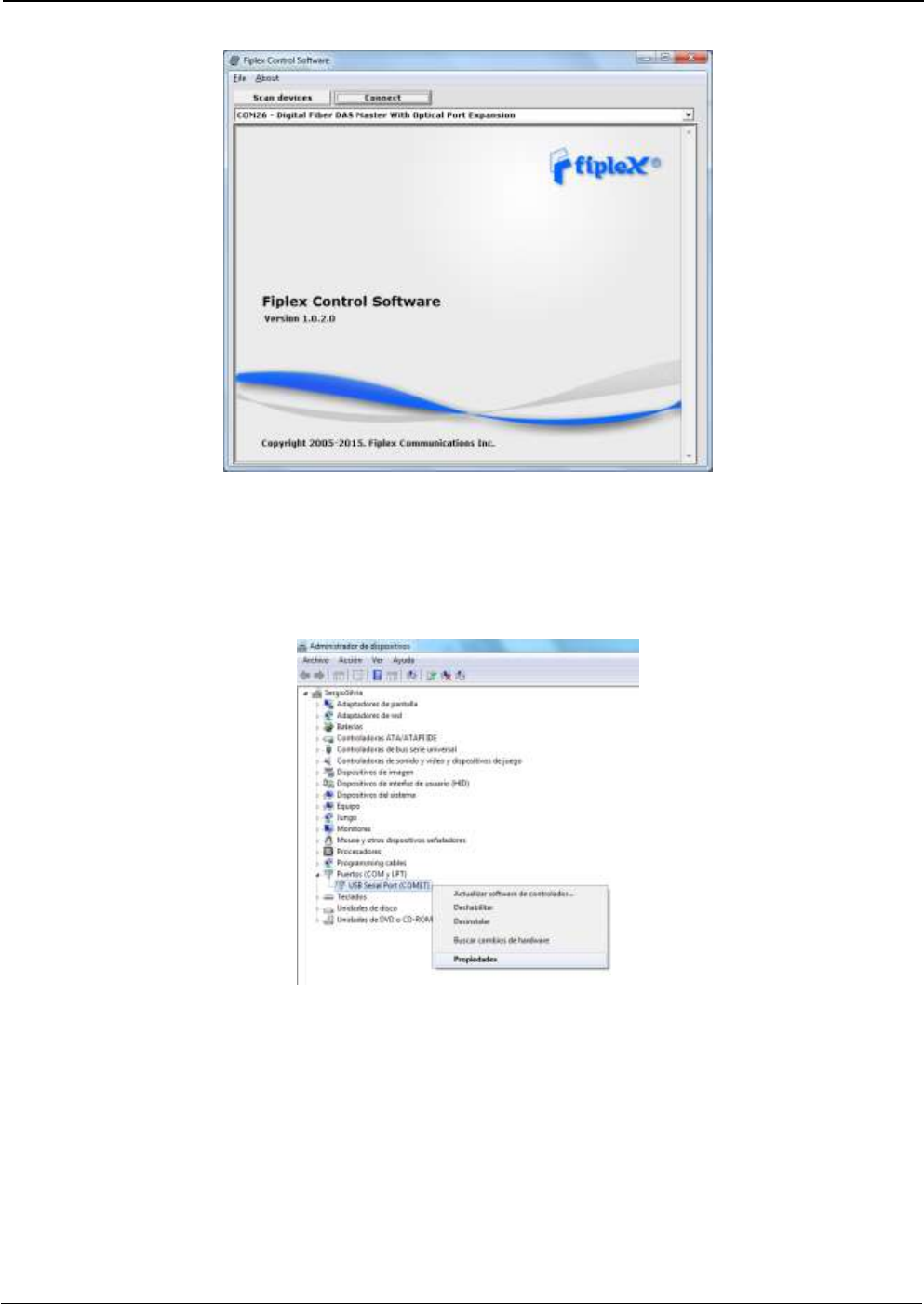
UM-0840 41
Now, the Fiplex unit is shown in the list of available devices, and connection button is
enabled.
NOTE: Fiplex repeater could not appear in list, if COM port number is higher than
COM16, depending on Windows version. COM port number can be forced to arbitrary
number (below COM16) through Device Administrator. In order to change COM number,
click “Properties” pop-up menu:
Click “Advanced Options”
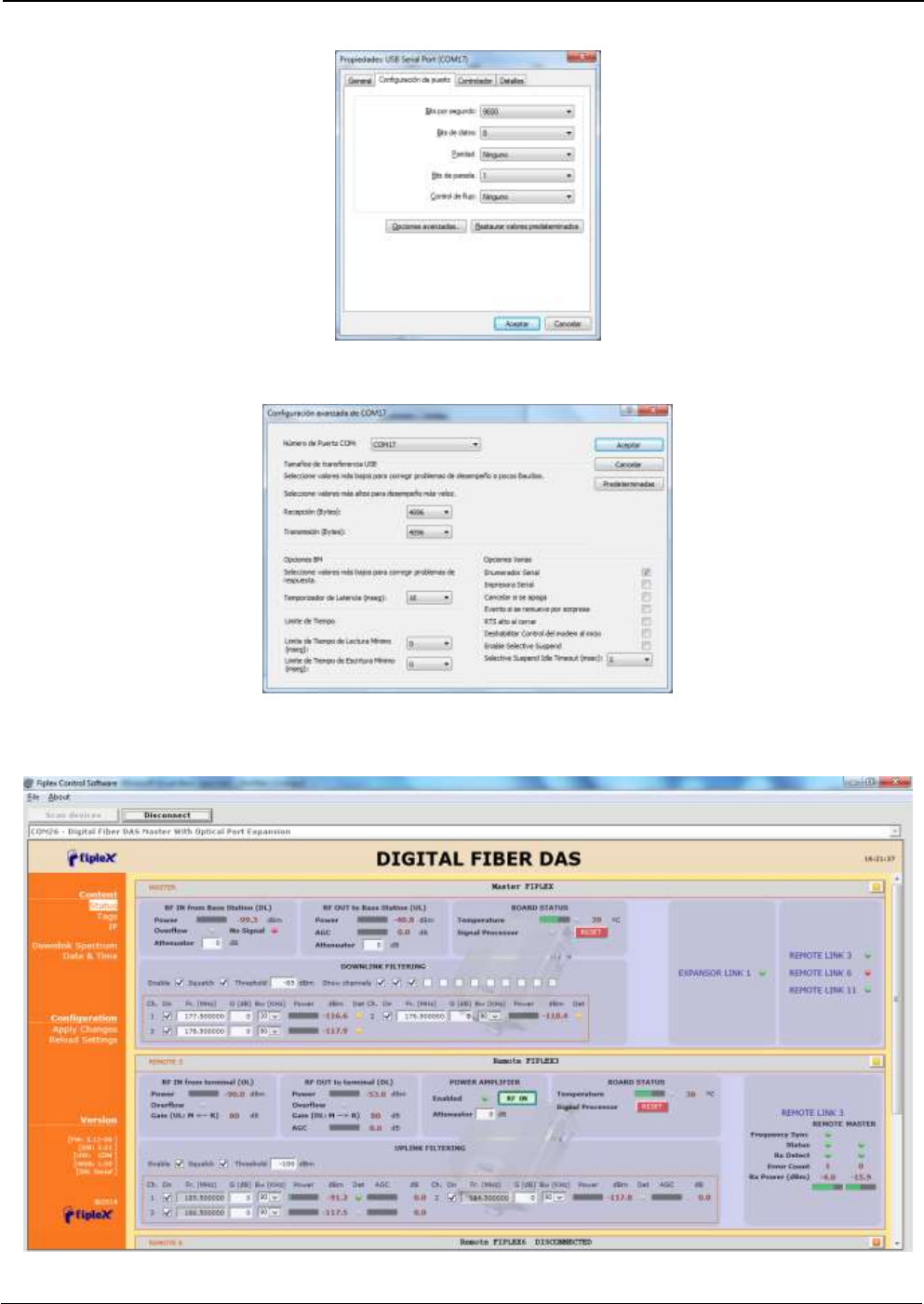
UM-0840 42
Change COM port number
9. Click “Connect”. Fiplex Control Software window will be automatically maximized, and it
will show the configuration screen described in previous sections.
UM-0840 43
10. Once system is configured, user can disconnect software using connection button, now
labelled “Disconnect”. Initial window will be shown.
If repeater is disconnected or turned off, while Fiplex Control Software is connected to
device, software will go back to initial window. Moreover, if some communication problem
occurs while device is monitored, the software will go back to initial state as well.
11. Remote unit can be controlled through USB port. In this case, Fiplex Control Software will
show that connected device is a remote unit.
After click on “Connect” button, program will show only remote configuration and
monitoring parameters, with same graphical interface described in previous sections:
UM-0840 44