Fiplex Communications DH7SX 700/800 MHz Dual Band Industrial Booster User Manual
Fiplex Communications Inc 700/800 MHz Dual Band Industrial Booster
UserManual.wiki
>
Fiplex Communications
>
DH7SX User Manual
User Manual
Navigation menu
Upload a User Manual
Namespaces
Wiki Guide
HTML
PDF
Info
Views
User Manual
Discussion / Help
Navigation


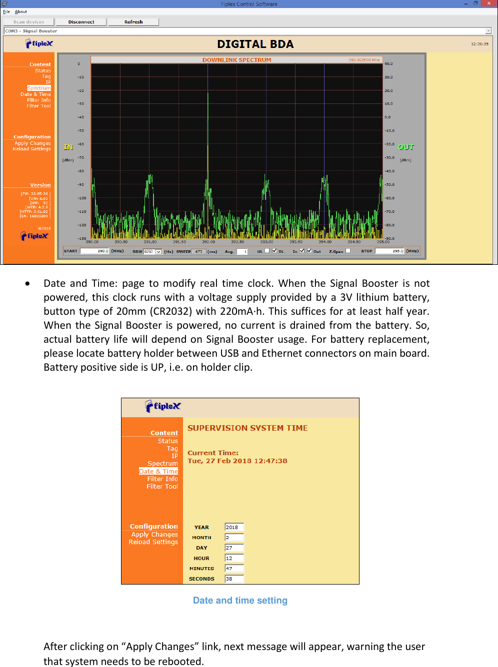
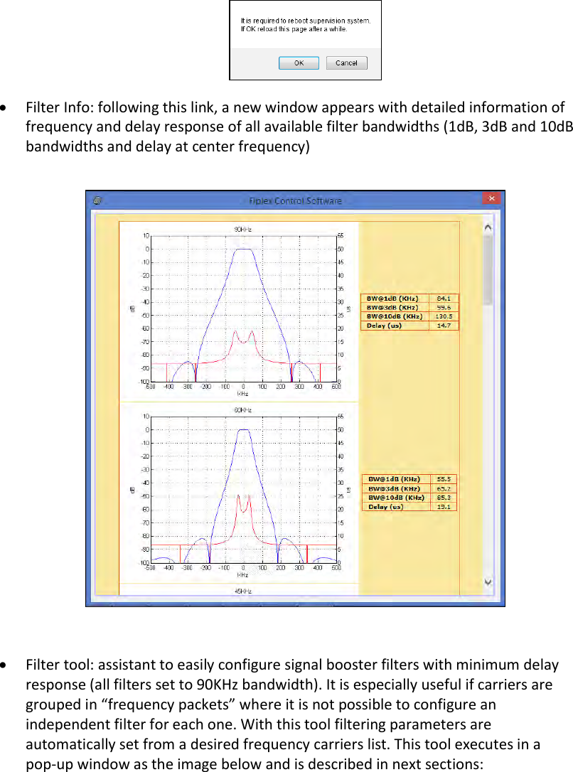
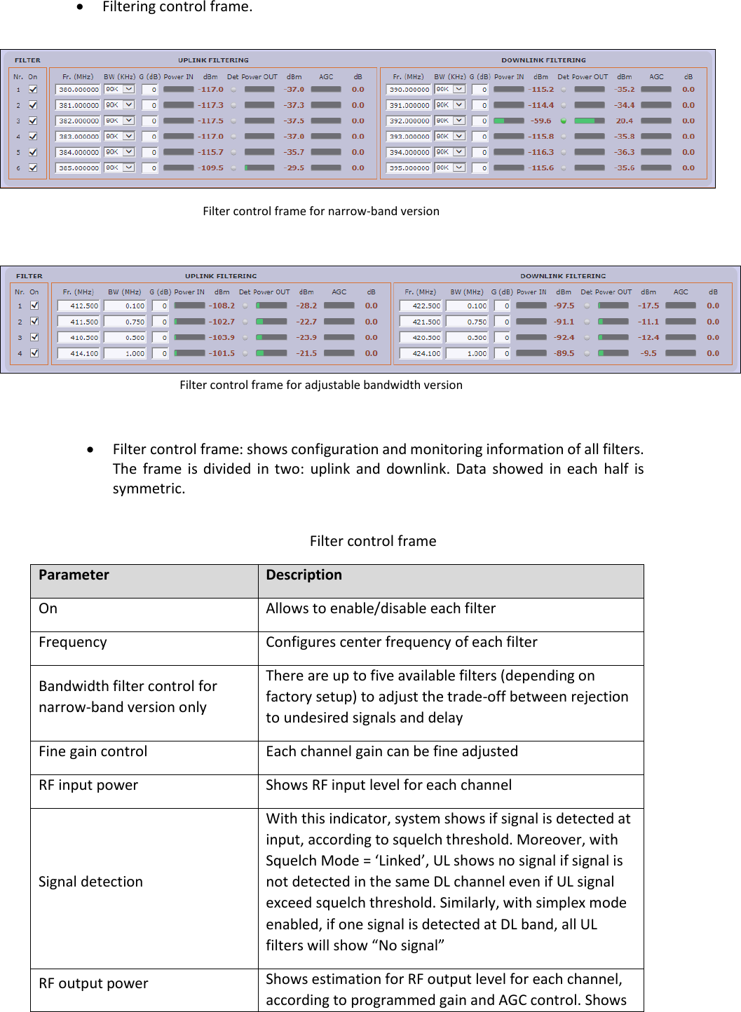
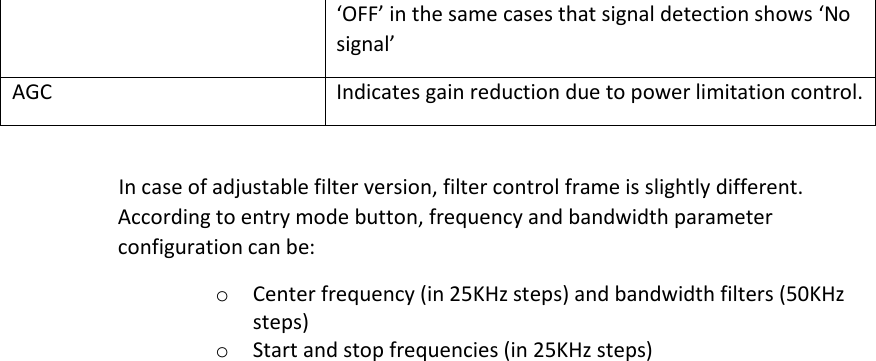
![SNMP Agent Fiplex Signal Booster includes a SNMPv1 agent that allows user to supervise the device by means of 'SET' and 'GET' type commands and, asynchronous traps to notify alarm conditions can be sent. The device is intended to be monitored by a polling NMS but it can send traps to a NMS or Trap Receiver if enabled. Fiplex can provide a NMS system upon request. The following sections will show the user configurable, relevant information that can be read via SNMP from the device. The tables will describe these values in order to explain how the information has to be read and interpreted. MIB Description The associated MIB document is FIPLEX-BDA-SYSTEMv13-MIB.mib. The Fiplex MIB is divided into blocks. Each block describes the characteristics and values of a specific element but not all elements are implemented in this agent. Each MIB block is divided in two segments, named 1T and 2T. Segment 1T contains the information that is fixed & read only. Segment 2T has the information that can vary over time, regardless of it being read/only or read/write. The following sections will show the user configurable, relevant information that can be read via SNMP from the device. Manager This is a table with 2 consecutive elements, one for each NMS. No checking is done of the validity of the information stored in the table, so extra care must be taken by the user. SNMP Managers table Field Name OID Description Type Man2TAddress[0] 1.3.6.1.4.1.26355.2.50.3.2.1.2.0 First NMS Address R/W Man2TAddress[1] 1.3.6.1.4.1.26355.2.50.3.2.1.2.1 Second NMS Address R/W Man2TPort[0] 1.3.6.1.4.1.26355.2.50.3.2.1.3.0 First NMS Port where to send traps R/W Man2TPort[1] 1.3.6.1.4.1.26355.2.50.3.2.1.3.1 Second NMS Port where to send traps R/W](https://usermanual.wiki/Fiplex-Communications/DH7SX/User-Guide-4169954-Page-62.png)
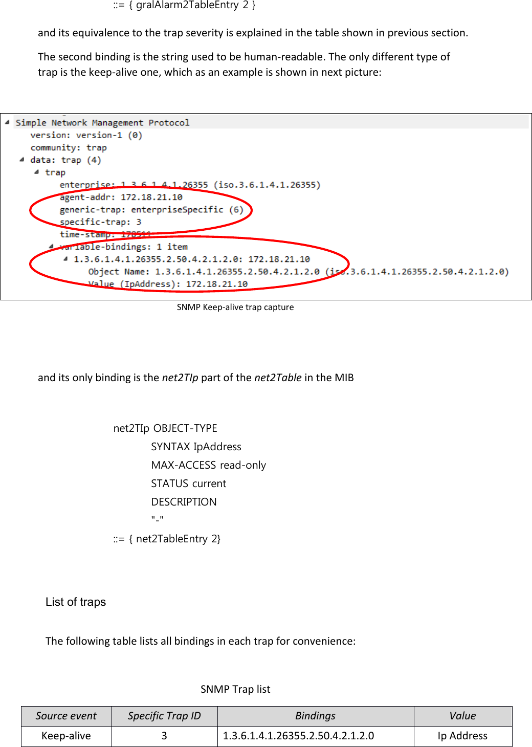
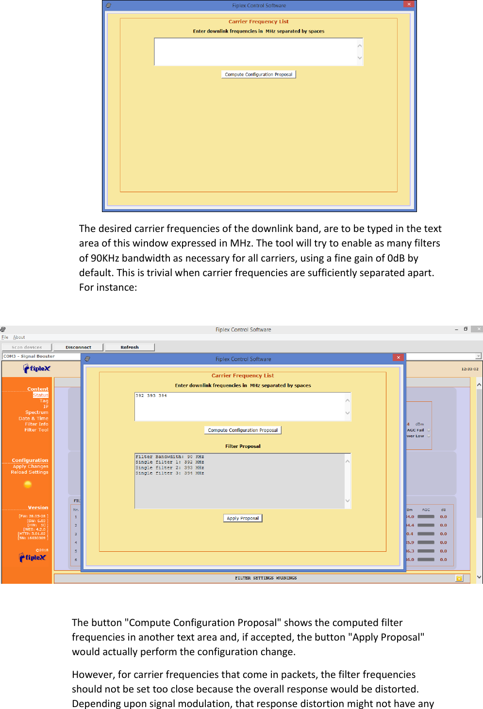
![Man2TEnable[0] 1.3.6.1.4.1.26355.2.50.3.2.1.5.0 First NMS. 1= Enabled, 2=Disabled R/W Man2TEnable[1] 1.3.6.1.4.1.26355.2.50.3.2.1.5.1 Second NMS. 1= Enabled, 2=Disabled. R/W Man2TAliveNotificationPeriod[0] 1.3.6.1.4.1.26355.2.50.3.2.1.6.0 First NMS. If enabled in Man2TEnable, defined time between keep-alive traps. R/W Man2TAliveNotificationPeriod[1] 1.3.6.1.4.1.26355.2.50.3.2.1.6.1 Second NMS. If enabled in Man2TEnable, defined time between keep-alive traps. R/W The following MIB tree representation shows this table: SNMP Managers table The following picture shows the same table as seen by the Fiplex NMS:](https://usermanual.wiki/Fiplex-Communications/DH7SX/User-Guide-4169954-Page-63.png)
![NMS: SNMP Managers table Network This is a table has just one element with two items. The first one is the device's IP address and it is read-only to avoid unwanted miss-configuration. This can only be changed by means of the embedded web server or locally, through USB, by means of the Fiplex Control Software. The second item is a “kind” of button intended for resetting the embedded Ethernet hardware interface. SNMP Network table Field Name OID Description Type Net2TIp[0] 1.3.6.1.4.1.26355.2.50.4.2.1.2.0 IP address R/O Net2TResetNetwork[0] 1.3.6.1.4.1.26355.2.50.4.2.1.3.0 Network reset: reads as idle(1), sets to reset(2) R/W The following MIB tree representation shows this table and following there is the NMS view:](https://usermanual.wiki/Fiplex-Communications/DH7SX/User-Guide-4169954-Page-64.png)
![SNMP Network table NMS: SNMP Network table Device This is also a one element table, providing several informative fields, but only relevant and implemented one is the “Location” field, which allows to easily identify a device by a name provided by the user, usually related to the place where it is located. SNMP Device table Field Name OID Description Type Dev2TPowerOn[0] 1.3.6.1.4.1.26355.2.50.5.2.1.2.0 - R/W](https://usermanual.wiki/Fiplex-Communications/DH7SX/User-Guide-4169954-Page-65.png)
![Dev2TLocation[0] 1.3.6.1.4.1.26355.2.50.5.2.1.3.0 String with up to 30 characters R/W Dev2TConnectionStatus[0] 1.3.6.1.4.1.26355.2.50.5.2.1.4.0 - R/O Dev2TMainPowerStatus[0] 1.3.6.1.4.1.26355.2.50.5.2.1.5.0 - R/O Dev2TBatteryStatus[0] 1.3.6.1.4.1.26355.2.50.5.2.1.6.0 - R/O Dev2TIsolationStatus[0] 1.3.6.1.4.1.26355.2.50.5.2.1.7.0 - R/O Dev2TDoorStatus[0] 1.3.6.1.4.1.26355.2.50.5.2.1.8.0 - R/O MIB tree view: SNMP Device table The Fiplex NMS view shows this table under the tab named “info”:](https://usermanual.wiki/Fiplex-Communications/DH7SX/User-Guide-4169954-Page-66.png)
![NMS: SNMP Device table Additional information is shown by clicking on the link named “Description”. This extra piece of information comes from the fixed table, Dev1Table. The most relevant items in this table are the following ones: SNMP Device Group table Field Name OID Description Type Dev1TGroup[0] 1.3.6.1.4.1.26355.2.50.5.1.1.3.0 das.info (conformance group) R/O Dev1TurlExtern[0] 1.3.6.1.4.1.26355.2.50.5.1.1.19.0 URL of embedded web server R/O Alarms Alarms tables provide information regarding the status of key parts in the system. The fixed table gralAlarm1Table provides self-explanatory identifiers, gralAlarm1TId, for each relevant subject. The second item in each element of this table is the gralAlarm1TGroup. When the device being monitored is a Remote unit, this item just takes the value 'das.alarms '. However, since the Master unit carries information from all the devices in the whole DAS system, it provides a different value for each device to which the alarm is assigned to, be it the Master unit, any of the Remote units or any of the Expansion units. Therefore, the actual number of elements in this table for the Master unit, depends on how many devices compose the DAS system. The third item of each element, gralAlarm1TDescription, is left blank, since the first one suffices for that purpose. SNMP Alarm Group table Field Name OID Description Type](https://usermanual.wiki/Fiplex-Communications/DH7SX/User-Guide-4169954-Page-67.png)
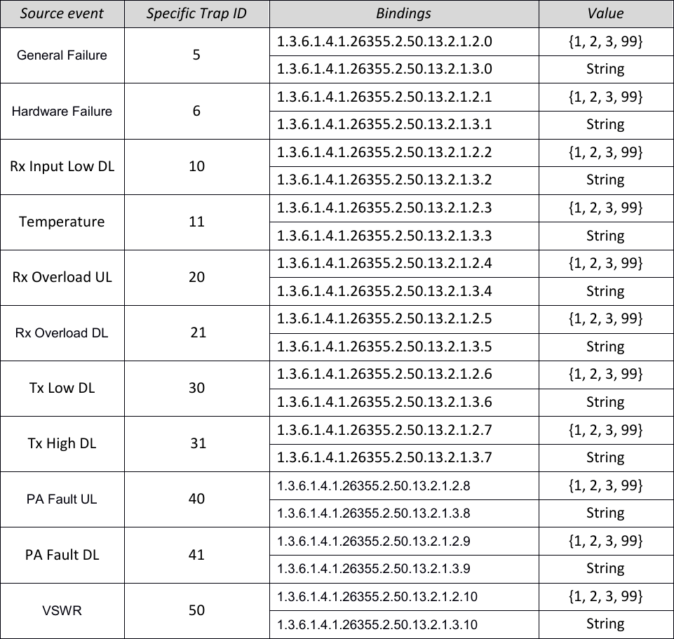
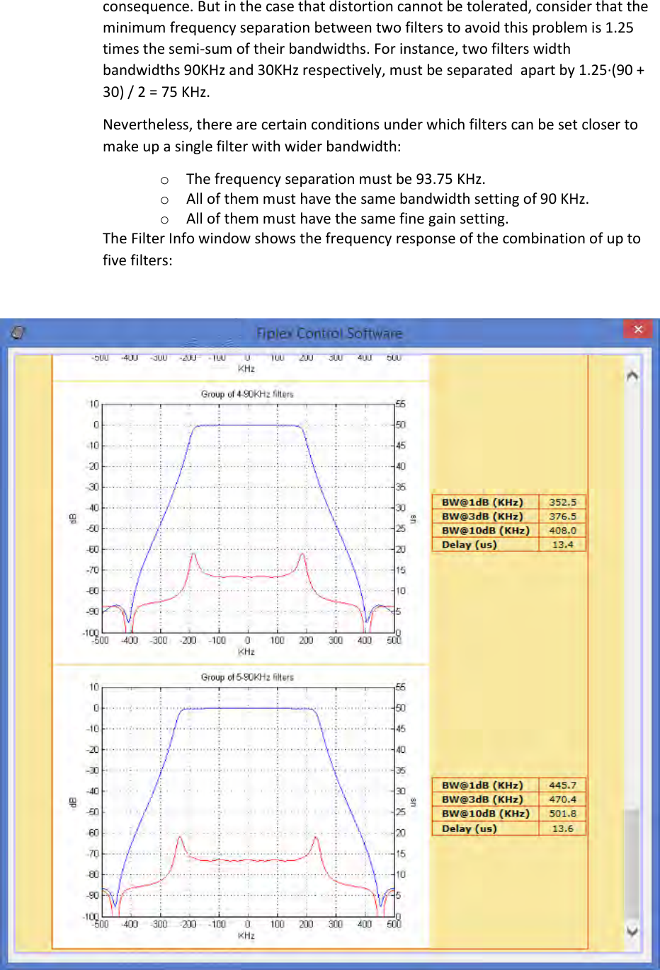
![GralAlarm1TId[0] 1.3.6.1.4.1.26355.2.50.13.1.1.2.0 Descriptive identifier string R/O GralAlarm1TGroup[0] 1.3.6.1.4.1.26355.2.50.13.1.1.3.0 Conformance group for general alarms R/O GralAlarm1TDescription[0] 1.3.6.1.4.1.26355.2.50.13.1.1.4.0 - R/O The alarm identifiers available are the following ones: AlarmGeneralFail Board malfunction that cannot be determined. AlarmHwFail Digital signal processor failure. AlarmRxLow No input signal is detected in the downlink direction in any of the activated filters. Aside from a faulty part, as the donor antenna or RF cable, this also might be caused be a problem with the base station or frequency configuration. Notice also that signal detection is dependent on squelch threshold setting. Because of that, this is considered a warning instead of an alarm. AlarmTempHigh High device temperature (over 85ºC). AlarmOverloadUplink Excessive RF input signal in UL. AlarmOverloadDownlink Excessive RF input signal in DL. AlarmTxLowDownlink Detected RF output power much lower than expected. Since output power measurement is performed by the dedicated monitoring board, a fault in that board would make this item be set as Unavailable and AlarmPAFaultDownlink set to true. AlarmTxHighDownlink Excessive RF output power detected (3dB higher than rated). This is most likely due to bad gain settings, since AGC would limit output power otherwise. AlarmPAFaultUplink Uplink Power Amplifier failure. This alarm is available for certain amplifier types only, and for the rest an 'unavailable' status is set in the next table. AlarmPAFaultDownlink Downlink Power Amplifier failure. A communication failure with the dedicated monitoring board itself, throws this alarm, too. AlarmVswr RF mismatch of PA output is detected. Since VSWR measurement is performed by the dedicated monitoring board, a fault in that board would make this item be set as Unavailable and AlarmPAFaultDownlink set to true.](https://usermanual.wiki/Fiplex-Communications/DH7SX/User-Guide-4169954-Page-68.png)
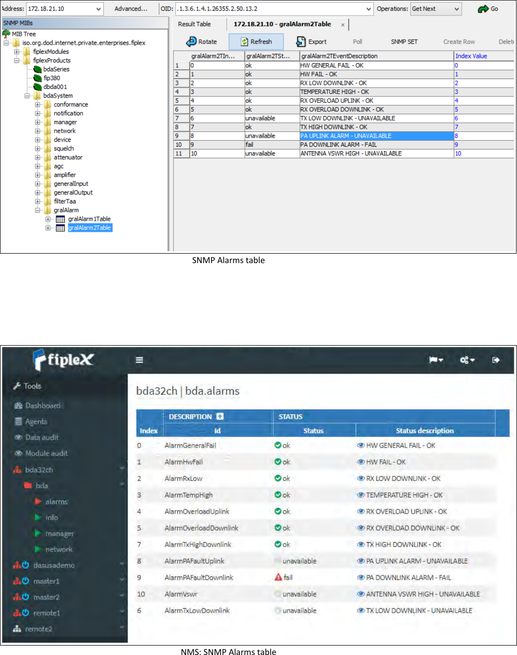
![SNMP Alarms Group table On the other hand, the mutable table gralAlarm2Table provides the actual status of each alarm. This table has one element for each element in gralAlarm1Table. Each element has two items. The first one is a status identifier, gralAlarm2TStatus, be it 'ok', 'warning', 'fail' or 'unavailable'. The second item is a short description of the fault, mainly for human readability. SNMP Alarm table 2 Field Name OID Description Type GralAlarm2TStatus[0] 1.3.6.1.4.1.26355.2.50.13.2.1.2.0 Status enumeration R/O GralAlarm2TEventDescription[0] 1.3.6.1.4.1.26355.2.50.13.2.1.3.0 Short descriptive string R/O The next picture is the MIB tree view of this table, and the Fiplex NMS provides a combined view of both tables and groups alarms:](https://usermanual.wiki/Fiplex-Communications/DH7SX/User-Guide-4169954-Page-69.png)