Fiplex Communications DHS00-M PS800 DIGITAL MASTER UNIT User Manual TETRA User s Manual
Fiplex Communications Inc PS800 DIGITAL MASTER UNIT TETRA User s Manual
UserManual.wiki
>
Fiplex Communications
>
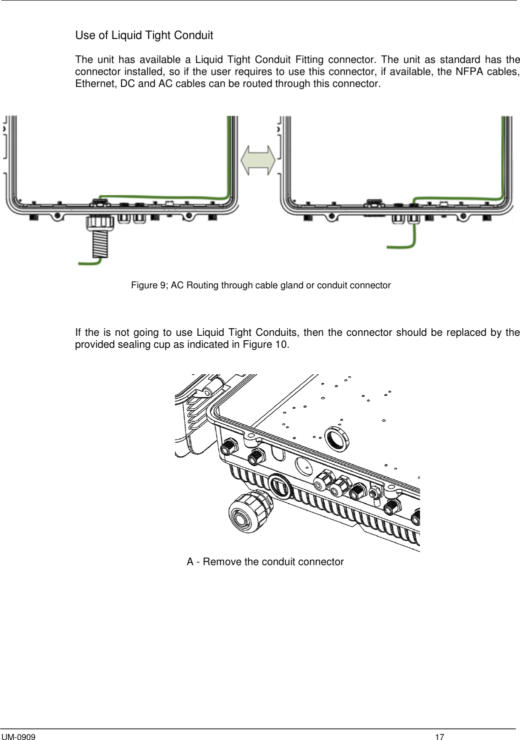
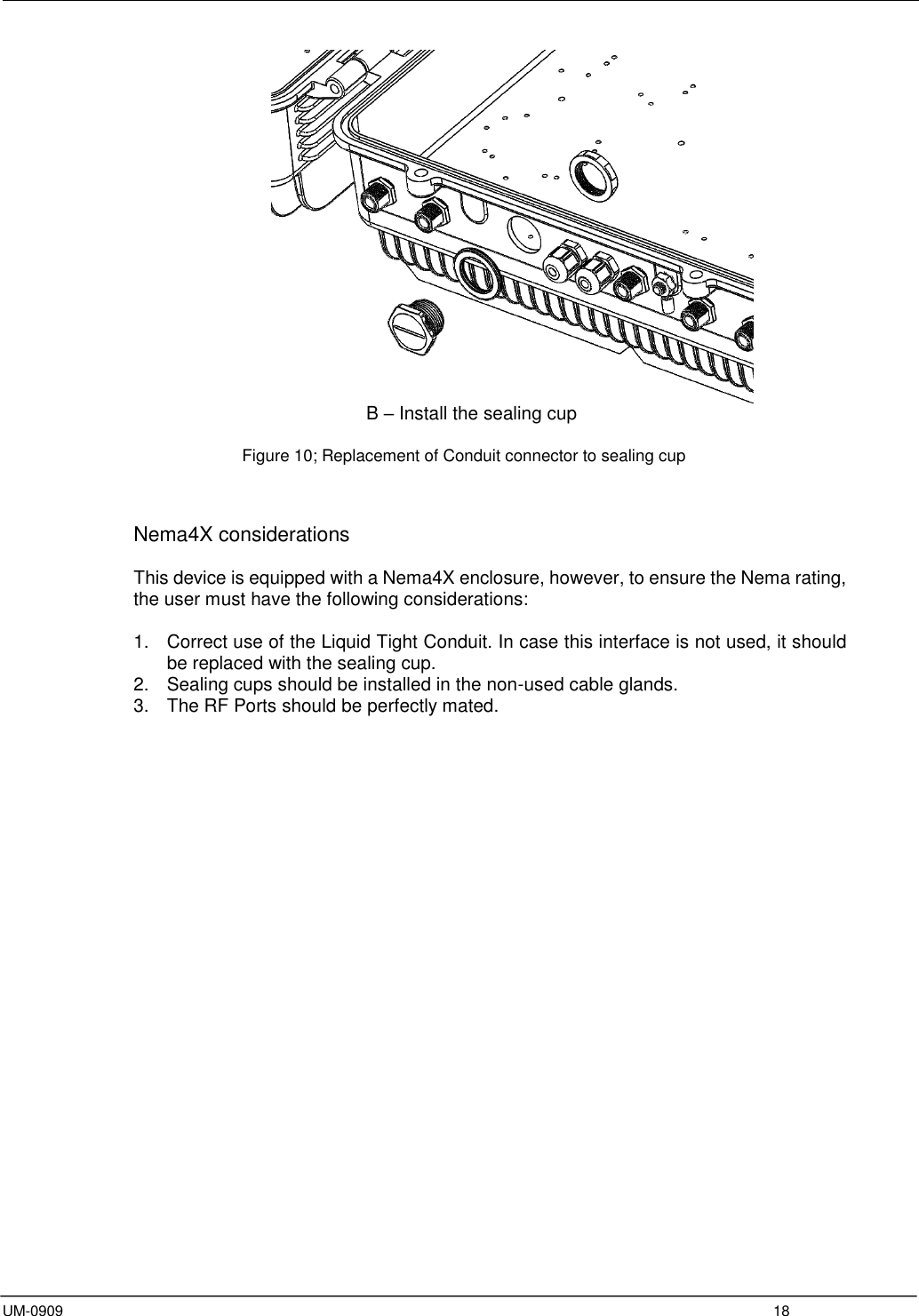
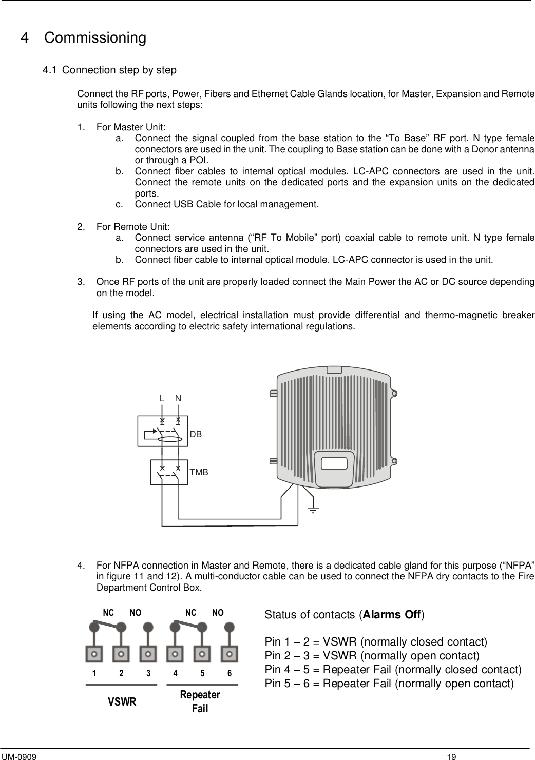
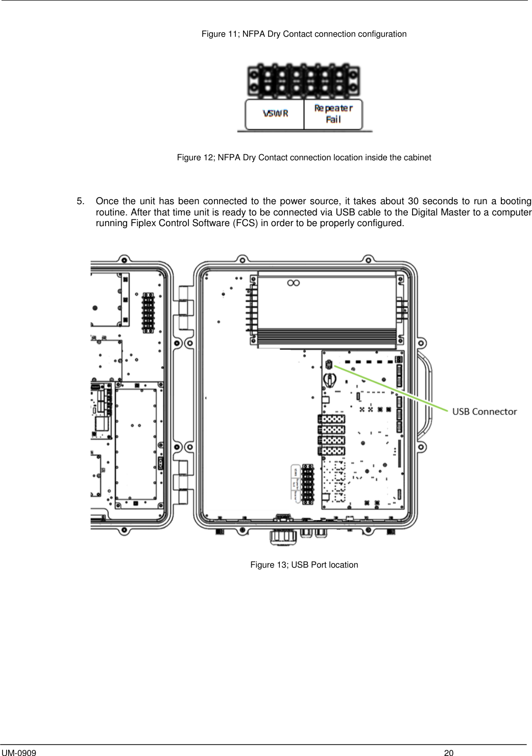
DHS00 M User Manual
User Manual
Navigation menu
Upload a User Manual
Namespaces
Wiki Guide
HTML
PDF
Info
Views
User Manual
Discussion / Help
Navigation