Fiplex Communications DHS40-HG-SCH Single Channel Amplifier User Manual TETRA User s Manual

Fiplex Communications Inc Single Channel Amplifier TETRA User s Manual

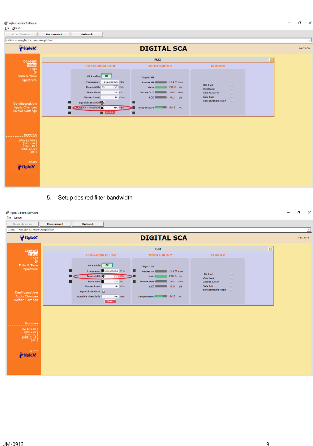
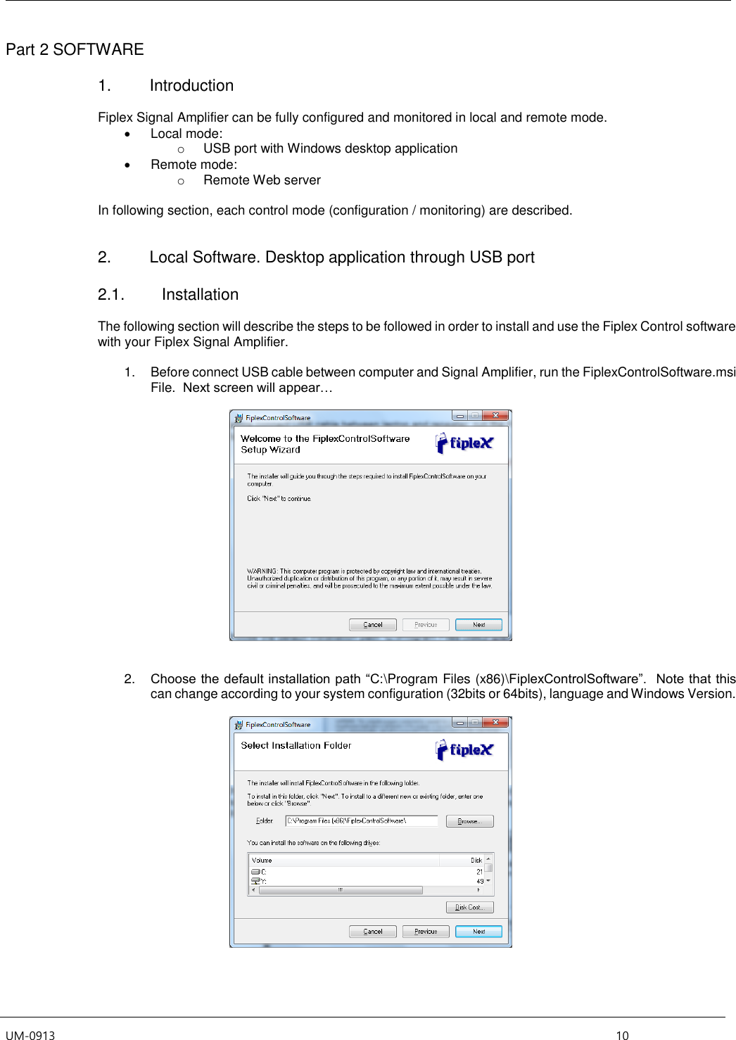
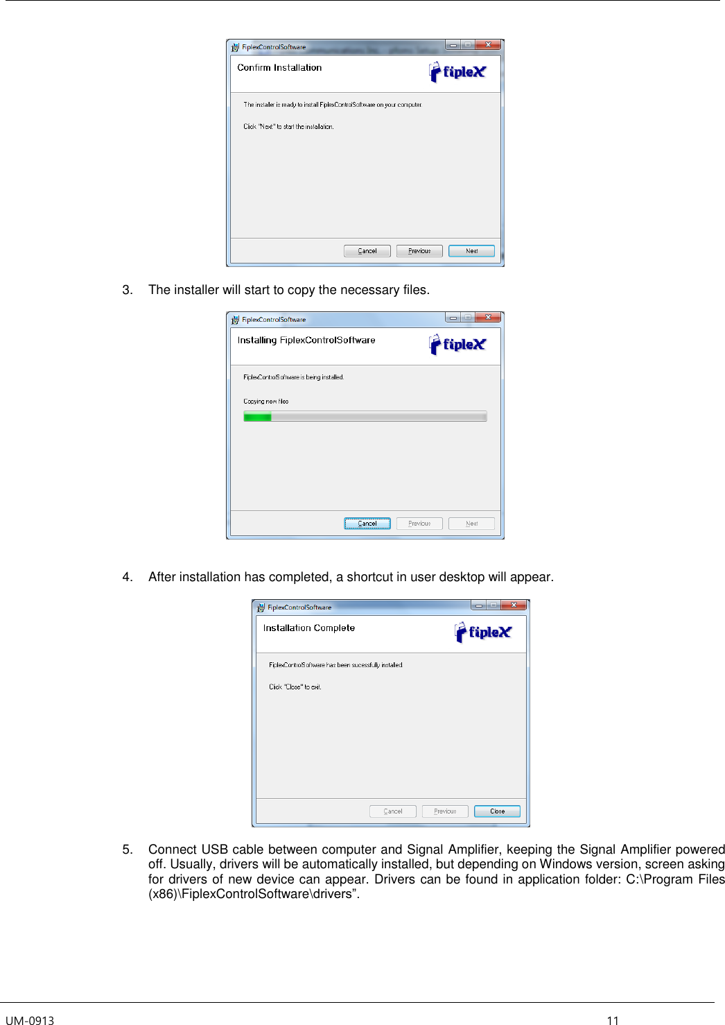
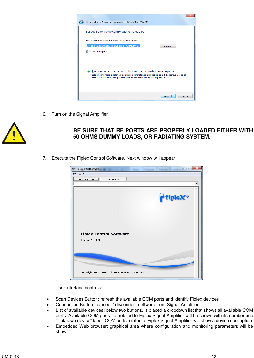
User Manual DHS40-HG-SCH

 UM-0913    1                English         DHS40-HG-SCH - Signal Amplifier User & Installation Manual
 UM-0913    2 Document History   Description Revision Date Issued Original 1.0 June 1st, 2015 Update SAR values 2.0 July 20th, 2017
 UM-0913    3 About this manual  This manual describes installation, commissioning, operation and maintenance of Fiplex DHS40-HG-SCH Signal Amplifier, and Fiplex Control Software (FCS). The first part of the manual describes the Signal Amplifier hardware and the second part describes the software.  Hardware and software mentioned in this manual are subjected to continuous development and improvement. Consequently, there may be minor discrepancies between the information in the manual and the performance and design of the hardware and software. Specifications, dimensions and other statements mentioned in this manual are subject to change without notice.                                            This manual or parts of it may not be reproduced without the written permission of Fiplex Communications Inc. Infringements will be prosecuted. All rights reserved. Copyright © Fiplex Communications Inc, Miami, 2017.
UM-0913  4 Exposure Statement ATTENTION: This unit has a maximum output power of +40dBm +/- 2dBm, therefore the gain of the antenna should be of 0dBi or less and maintain a minimum separation of 40 cm from all persons to comply with SAR and/or RF field strength limits.
 UM-0913    5 Part 1 HARDWARE  1.  Safety  Caution! This manual lists a set of rules and warnings to be accomplished when installing, commissioning and operating a DHS40-HG-SCH Signal Amplifier from FIPLEX. Any omission may result in damage and/or injuries to the Amplifier and/or the Amplifier Operators or Users.  If  an  instruction  is  not  clear  or  you  consider  is  missing,  please  contact  immediately  to  Fiplex.  See www.fiplex.com for contact information.  Dangerous Voltage Warning Any personnel involved in installation, operation or service of this equipment must understand and obey the following:  The power supply unit supplied from the main power contains dangerous voltage level, which can cause electric shock. Switch the main power off prior to any work in such equipment. Any local regulations are to be followed when servicing Signal Amplifiers.  Authorized  service  personnel  only  are  allowed  to  service  Signal Amplifiers while the main is switched on.   R&TTE Compliance Statement This  equipment  complies with  the  appropriate  essential  requirements of  Article  3 of  the  R&TTE  Directive 1999/5/EC.    Station Ground     Signal Amplifiers, feeders, donor antenna, service antenna/s and auxiliary equipment (splitters, tabs, etc.) are required to be bonded to protective grounding using the bonding stud or screw provided with each unit.    Electrostatic Discharge Static electricity means no risk of personal injury but it can severely damage essential parts of the  Signal Amplifier, if not handled carefully. Parts on the printed circuit boards as well as other parts in the Signal Amplifier are sensitive to electrostatic discharge. Never touch printed circuit boards or uninsulated conductor surfaces unless absolutely necessary. If you must handle printed circuit boards or uninsulated conductor surfaces, use ESD protective equipment, or first touch the Signal Amplifier chassis with your hand and then do not move your feet on the floor. Never let your clothes touch printed circuit boards or uninsulated conductor surfaces.   Disposal of Electric and Electronic Waste Pursuant to the WEEE EU Directive electronic and electrical waste must not be disposed of with unsorted waste. Please contact your local recycling authority for disposal of this product.
 UM-0913    6 2.  Product Description.  The DHS40-HG-SCH Signal Amplifier are single channel amplifiers that operates in the frequency range of 806-824MHz for United States.   This Signal Amplifiers amplifies the RF signal of a Base Station or Transmitter equipment without the need of a previous amplification (driver, power amplifier).   The system receives the BTS or Transmitter signal to be amplified, filters, amplifies and re-radiates through the connected antenna/s.   This signal amplifier is capable of handling one single channel, narrow band. It is not intended to be used as a multiple  carrier  signal amplification. The channel  BW  and frequency position can be  tuned  via a software interface.    The intermediate filtering of this equipment is performed using FPGA filtering technology and, among many, it has the following features: - High Selectivity. - Channel filter BW selection.  This Signal Amplifier has a compact heavy duty 2 RU cabinet for indoor usage.
 UM-0913    7    3.  Ports    4.  Commissioning   1. Connect RF IN and RF OUT. N type female connectors are used in the Signal Amplifier.  2. Once RF ports of the Signal Amplifier are properly loaded connect the DC port. Electrical installation must provide differential and termo-magnetic breaker elements according to electric safety international regulations.  3. Signal Amplifier chassis must be properly DC grounded.   4. Turn ON DC power.  5. Once the Signal Amplifier has been powered, it takes about 20 seconds to run a booting routine. After that time Signal Amplifier is ready to be connected via USB cable to a computer running FCS Software in order to be properly configured. See Part 2 Software of this manual to install FCS.   5.  Starting Operation    BE SURE THAT BOTH RF PORTS ARE PROPERLY LOADED EITHER WITH 50 OHMS DUMMY LOADS, OR RADIATING SYSTEMS.   1.  Turn on the Signal Amplifier, connect computer to Signal Amplifier through USB cable, and run Fiplex Control Software.  2.  Setup desired channel frequency. Since Signal Amplifier is a single channel device, user has to know what frequency is used in Base Station or Transmitter.
 UM-0913    8    3.  Setup desired operating gain using FCS.     4.  Set up squelch settings.
 UM-0913    9   5.  Setup desired filter bandwidth
 UM-0913    10 Part 2 SOFTWARE  1.  Introduction  Fiplex Signal Amplifier can be fully configured and monitored in local and remote mode.   Local mode: o  USB port with Windows desktop application   Remote mode: o  Remote Web server  In following section, each control mode (configuration / monitoring) are described.    2.  Local Software. Desktop application through USB port  2.1.  Installation  The following section will describe the steps to be followed in order to install and use the Fiplex Control software with your Fiplex Signal Amplifier.  1.  Before connect USB cable between computer and Signal Amplifier, run the FiplexControlSoftware.msi File.  Next screen will appear…      2. Choose the default installation path “C:\Program Files (x86)\FiplexControlSoftware”.  Note that this can change according to your system configuration (32bits or 64bits), language and Windows Version.
 UM-0913    11   3.  The installer will start to copy the necessary files.     4.  After installation has completed, a shortcut in user desktop will appear.    5.  Connect USB cable between computer and Signal Amplifier, keeping the Signal Amplifier powered off. Usually, drivers will be automatically installed, but depending on Windows version, screen asking for drivers of new device can appear. Drivers can be found in application folder: C:\Program Files (x86)\FiplexControlSoftware\drivers”.
 UM-0913    12    6.  Turn on the Signal Amplifier   BE SURE THAT RF PORTS ARE PROPERLY LOADED EITHER WITH 50 OHMS DUMMY LOADS, OR RADIATING SYSTEM.    7.  Execute the Fiplex Control Software. Next window will appear:    User interface controls:    Scan Devices Button: refresh the available COM ports and identify Fiplex devices   Connection Button: connect / disconnect software from Signal Amplifier   List of available devices: below two buttons, is placed a dropdown list that shows all available COM ports. Available COM ports not related to Fiplex Signal Amplifier will be shown with its number and “Unknown device” label. COM ports related to Fiplex Signal Amplifier will show a device description.   Embedded Web browser: graphical area where configuration and monitoring parameters will be shown.
 UM-0913    13   File menu: contains menus to save Signal Amplifier configuration to a file and load configuration from file to Signal Amplifier.  NOTE: if Fiplex Signal Amplifier is not turned on, related COM port will appear as “Unknown device”   8. Click “Scan Devices”    Now, the Fiplex Digital Signal Amplifier is shown in the list of available devices, and connection button is enabled. NOTE: Fiplex Signal Amplifier could not appear in list, if COM port number is higher than COM16, depending  on  Windows  version.  COM  port  number  can  be  forced  to  arbitrary  number  (below COM16) through Device Administrator. In order to change COM number, click “Properties” pop-up menu:     Click “Advanced Options”
 UM-0913    14   Change COM port number    9. Click “Connect”.  Fiplex Control Software window will be automatically maximized, and web browser will show the configuration screen. Application screens are described in the next section due to these application screens and web pages (in webserver remote mode) are the same.
 UM-0913    15   10.  Once  Signal  Amplifier  is  configured,  user  can  disconnect  software  using  connection  button,  now labelled “Disconnect”. Initial window will be shown.  If Signal Amplifier is disconnected or turned off, while Fiplex Control Software is connected to device, software will go back to initial window. Moreover, if some communication problem occurs while device is monitored, the software will go back to initial state as well.

Navigation menu