Firetide 1500R-1 802.11a Mesh Networked Ethernet Service Point User Manual
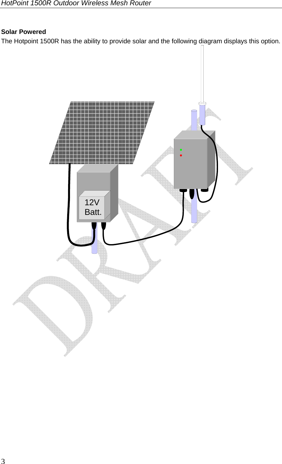
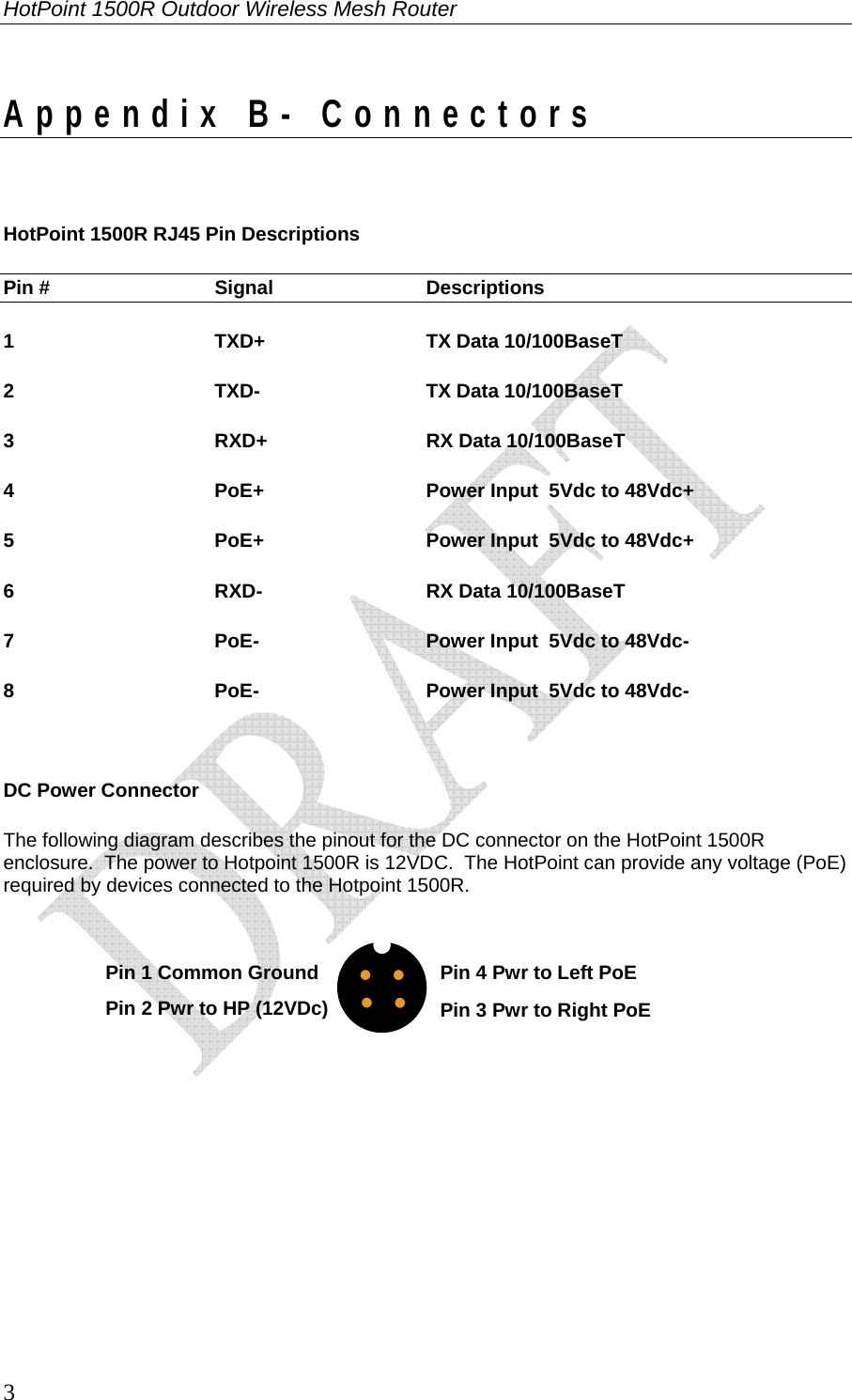
Firetide Inc. 802.11a Mesh Networked Ethernet Service Point
UserManual.wiki
>
Firetide
>
1500R 1 User Manual
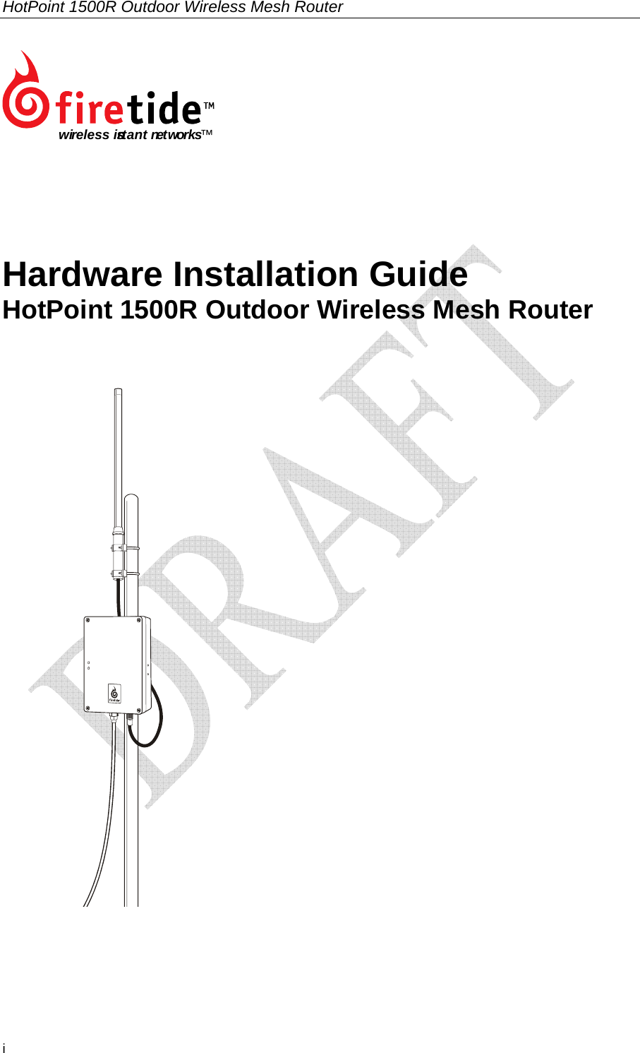
User Manual
Navigation menu
Upload a User Manual
Namespaces
Wiki Guide
HTML
PDF
Info
Views
User Manual
Discussion / Help
Navigation