Firetide 2100-1 HotClient Customer Premises Equipment, Model 2100 User Manual Manual
Firetide Inc. HotClient Customer Premises Equipment, Model 2100 Manual
Firetide >
Manual
HotClient
Manual Revision 1.0 012908
The contents of this Installation Guide are subject to change without notice.
Please refer to the Firetide partners web site, partners.retide.com, for current versions.
Hardware Installation Guide
HotClient 2100 / 2200
Customer Premises Equipment
Model 2100 Indoor CPE Model 2200 Outdoor CPE
2 CPE Hardware Guide January 2008
Firetide Limited End User Product Warranty
Pursuant to all provisions described herein, Firetide hardware products and Firetide antennas are warranted
for one (1) year from the date of purchase against defects in the build materials and workmanship. Firetide
does not warrant that the Products will meet any requirements or specications of any End User Customer.
This warranty applies to the entire Firetide product, including the AC power adapter.
Pursuant to all provisions described herein, Firetide software products are warranted for ninety (90) days from
the date of purchase against defects in the build materials and workmanship. Firetide also warrants that the
Software will materially conform to the documentation supplied by Firetide with the Software. In the event
that the Software fails to materially conform to the documentation and an authorized Firetide reseller is noti-
ed in writing of such failure within the warranty period, Firetide or its reseller shall use commercially reason-
able efforts to promptly correct the nonconformity. Firetide does not warrant that the use of the Software will
be uninterrupted or error free.
The above warranties are void if the alleged defect cannot be veried by Firetide or if, as determined by
Firetide, the product failure was due to tampering, abuse, misuse, accident, shipping, handling, or storage; or
if the product has been installed, used, or maintained in a manner not described in the product user manual;
or if the product has been altered in any way; or if product serialization has been altered. Any attempt to
disassemble or repair the product by anyone other than Firetide immediately voids this warranty.
This warranty applies only to the original End User purchaser of the product and may not be transferred to any
other individual or entity.
THE FOREGOING ARE THE EXCLUSIVE WARRANTIES APPLICABLE TO THE PRODUCT INCLUDING THE SOFTWARE,
AND THE EXCLUSIVE REMEDY FOR DEFECTS IN THE PRODUCT. FIRETIDE DISCLAIMS ALL OTHER WARRANTIES,
WHETHER EXPRESS, IMPLIED, STATUTORY OR OTHERWISE, INCLUDING BUT NOT LIMITED TO IMPLIED WARRAN-
TIES OF MERCHANTABILITY, NON-INFRINGEMENT OR FITNESS FOR A PARTICULAR PURPOSE. SOME LAWS DO
NOT ALLOW THE EXCLUSION OF IMPLIED WARRANTIES SO TO THAT EXTENT THIS LIMITATION MAY NOT APPLY TO
YOU.
In no event will Firetide be liable for any special, incidental, consequential, punitive or indirect damages
whatsoever (including, without limitation, damages for loss of prots, business interruption, loss of informa-
tion, or other pecuniary loss) arising out of the use or inability to use the product or the performance, inter-
ruption or failure of the product, irrespective of the cause of action, even if Firetide has been advised of the
possibility of such damages. Firetide’s cumulative liability for all claims arising out of or in connection with
this warranty will not exceed the amount paid by the original End User purchaser to purchase the product.
The amounts payable for the product are based in part on these limitations and these limitations shall apply
notwithstanding the failure of essential purpose of any remedy. Some jurisdictions do not allow the exclusion
or limitation of incidental or consequential damages, so to that extent the above limitations or exclusions
may not apply to you.
By using the product the original End User purchaser agrees to and is bound by these terms and conditions.
In the event that a product fails to meet this warranty and Firetide’s authorized reseller is notied in writing
of such failure within the warranty period, Firetide shall, at its own discretion, either repair the product or re-
place it with the same or a functionally-equivalent product free of charge. Replacement products may contain
refurbished materials in whole or in part. Firetide will honor this warranty provided the product is returned
through an authorized Firetide reseller or dealer with shipping charges prepaid, along with a proof of purchase
describing the original purchase date and product serial numbers if applicable. The authorized reseller must
acquire a Return Materials Authorization (RMA) number from Firetide prior to returning any product. Firetide
does not accept shipments of defective products without shipping charges prepaid.
Copyright Notice: ©2003-2007 Firetide, Inc. All rights reserved. Trademarks: Firetide, the Firetide
logo, Instant Mesh Networks, HotPort, HotPoint, and HotClient are trademarks of Firetide, Inc. All
other trademarks are the property of their respective owners.
Firetide, Inc.
16795 Lark Avenue, Suite 200
Los Gatos, CA 95032 USA
Please contact your Firetide dealer for instructions on returning defective or damaged products for
repair or replacement. Do not return products to Firetide, Inc. Please keep all original packaging
materials in the event they are needed to return the product for servicing.
Firetide Instant Mesh Networks 3 January 2008
Chapter 1. Setting Up Your Equipment
Introduction The Firetide Model 2100 and 2200 HotClient Customer Premises Equipment (CPE) provide connec-
tivity to the Internet without the need for cable, DSL, or other wired connection. The HotClient
uses a radio connection to provide Ethernet-equivalent connectivity in your home or business.
You connect to the HotClient via a wired Ethernet connection. You can connect a single computer
or multiple devices on a LAN. You can also connect an 802.11 a/b/g/n access device, if desired.
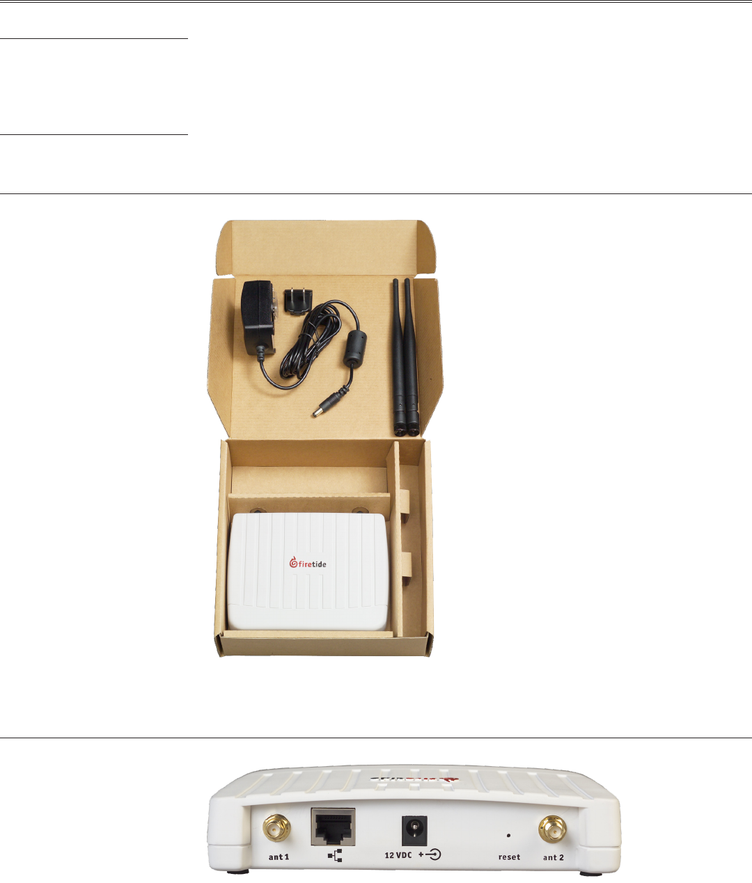
Unpacking and Setup - Indoor Setup of your new Firetide HotClient is simple. The package contents are shown in Figure 1.
Your HotClient needs power. Note that the AC adapter has interchangeable inserts to t most AC
receptacles in the US, Europe, the UK, Australia, and elsewhere. The adapter will operate on any
voltage from 100 to 240 VAC, from 50 to 60 Hz.
Figure 1. Series 2100 Indoor Unit - Package Contents
Your Firetide equipment needs to connect via a standard Ethernet (RJ-45) cable to your computer
or home network. Pick a suitable location for the device, and use the supplied power supply to pro-
vide power to the unit. The Power LED should illuminate immediately. Attach the supplied antennas
to the two antenna connectors. Tighten them rmly, by hand, and point them vertically.
Figure 2. Indoor Unit Important Points
The Firetide device needs about two minutes to boot itself and then nd the wireless signal. When
it completes this process, the Status LED will turn green.
Antenna 1 ResetPowerEthernet Antenna 2
4 CPE Hardware Guide January 2008
Setup - Outdoor If your ISP has chosen to use an outdoor HotClient, it will have been installed by a professional
installer. The installer will have provided a hard-wired Ethernet connection into your home or place
of business.
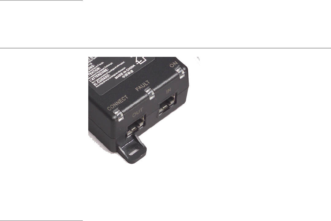
The Firetide HotClient does require power. Power is fed to it via the Ethernet cable. Connect the
power-feed unit to AC power. The ON light should turn green. Plug the cable from the HotClient
into the port marked OUT. The CONNECT light should turn green. If the FAULT light comes on, con-
tact your ISP.
Figure 3. Power-Feed Unit Connections.
Connect the device to your PC or home network via the RJ-45 connector. A crossover cable is NOT
required. Your Internet Service Provider has pre-congured your device. Set your computer to ob-
tain an IP address automatically (DHCP) and you can connect to the Internet.
Setup is now complete.
ISP-Provided Technical Support
and Warranty Services
If you need additional technical assistance, please contact your ISP directly. Your ISP is trained
and authorized to provide technical support and warranty services for Firetide products and has
qualied technical staff available to help you congure and maintain your Firetide Internet Con-
nection.
Firetide Instant Mesh Networks 5 January 2008
Chapter 2. Outdoor Installation
Introduction Installation of the Firetide HotClient outdoor device should only be done by qualied and expe-
rienced personnel. Outdoor installation involves many safety hazards, including electrocution,
lightning strikes, and falls. Please be careful.
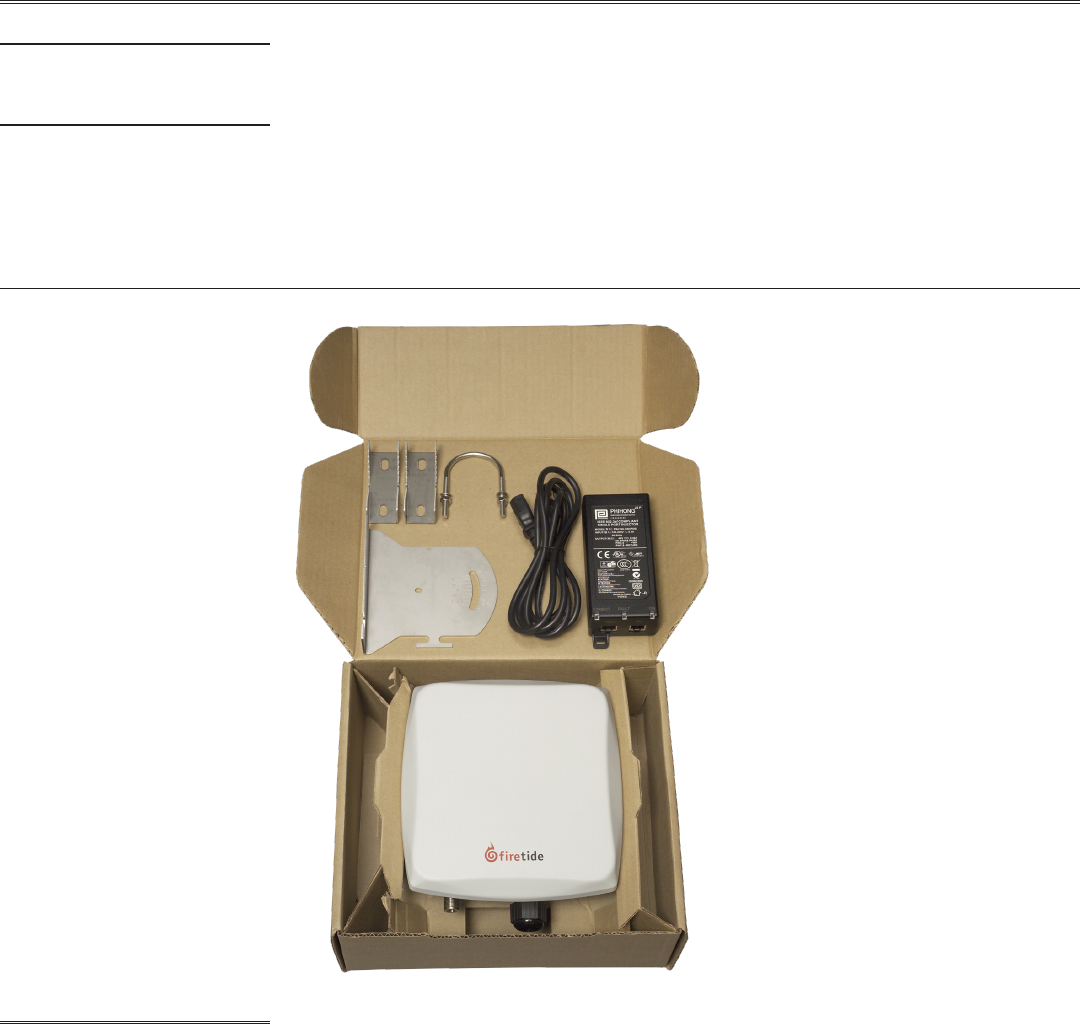
Unpacking and Setup - Outdoor The Firetide HotClient device is packed as shown in Figure 4. Note that an Ethernet cable is NOT
included. You should obtain a weatherproof 4-pair cat-5 cable long enough to reach from the
HotClient unit to the indoor location where you will connect with a PC, Ethernet switch, or other
equipment.
The cable must be a 4-pair cable; smaller cables will not seal in the waterproof connector. The
cable can be pre-terminated; the waterproof connector will pass an RJ-45 plug.
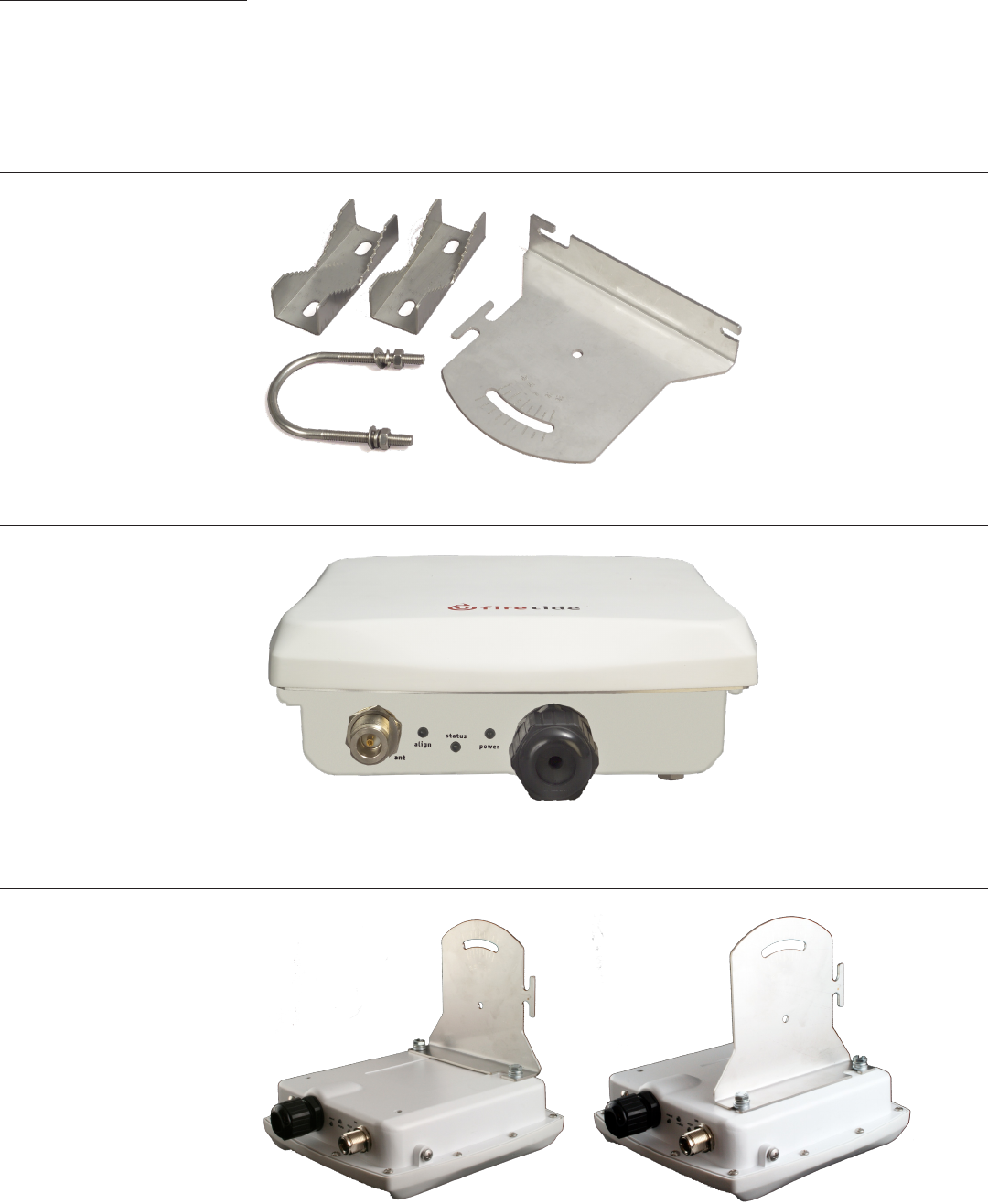
Figure 4. Series 2200 Outdoor Unit - Package Contents
Assembling the Ethernet Cable Test the unit before mounting it on the pole or mast. Begin by making the cable.
Remove the weatherproof Ethernet connector cover - the black plug - from the unit.1.
Dismantle it. You will have a housing, a housing insert, a cap, and a gasket.2.
Place the cap over one end of your Ethernet cable.3.
Place the housing insert over the cable.4.
Thread the cable through the housing.5.
Plug the cable into the RJ-45 port visible inside the HotClient.6.
Thread the housing back into the HotClient. Make sure the gasket is still in place.7.
Tighten the cap so that it compresses the housing insert to the housing.8.
Now you can connect the Ethernet cable to the power feed unit, via the OUT port on the power
feed unit. Use a second Ethernet cable to connect the IN port to your PC. Verify operation of the
HotClient before proceeding.
6 CPE Hardware Guide January 2008
Using the Mounting Bracket The bracket is designed to allow easy tilting and aiming of the HotClient device. The bracket allows
the HotClient to be mounted with its internal antenna oriented for either vertical or horizontal
polarization. It is also designed to allow mounting on either a horizontal or vertical pole. Note that
the internal antenna polarization is vertical when the connectors are pointed down.
Note that the antenna is built in to the HotClient. In general, the HotClient should face the equip-
ment it is intended to connect with. Typically this is a Firetide HotPoint AP.
There is an external antenna connector, but in most applications it is not needed. Keep the plastic
cover on this connected to prevent water from getting into the unit.
Figure 5. HotClient Mounting Bracket
In order to avoid climbing up and down the pole twice, power up the HotClient before proceeding
with the installation. The only connection you need is the Ethernet; it provides power as well.
Figure 6. HotClient Outdoor Unit Connections
Attach the bracket to the back of the HotClient, using the two slotted holes shown on the right side
of the bracket, as shown in Figure 5. Select two holes on the HotClient according to the desired
orientation of the pole and the antenna, as shown in Figure 7.
Figure 7. Attaching the Bracket to the HotClient
Firetide Instant Mesh Networks 7 January 2008
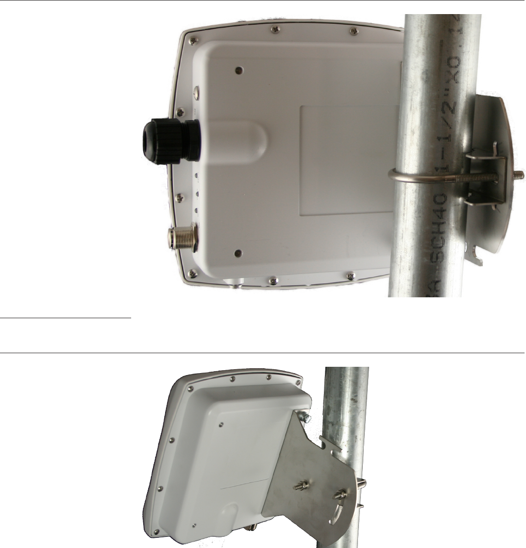
The bracket is attached to the pole using the U-bolt and one or two of the supplied jaw-clamps
(top left in Figure 5). One jaw-clamp is used between the bracket and the pole; the second clamp
may be used on smaller-diameter poles by placing it over the U-bolt before putting the U-bolt
around the pole.
After placing the U-bolt around the pole, place the bracket over the legs of the U-bolt such that
one leg passes through the round hole and the other leg passes through the curved slot. Snug the
bracket slightly with the supplied nuts and lockwashers, but do not tighten until you have aligned
the unit. The result should resemble Figure 8.
Figure 8. U-bolt Mounting Assembly
Aligning the HotClient The Alignment LED provides a visual indication of signal strength. Point the HotClient in the direc-
tion of its signal source, then carefully adjust it, both horizontally and vertically, using the Align-
ment LED as a guide. When you receive the strongest signal, tighten the nuts. Figure 9 shows how
the bracket can be used to tilt the unit.
Figure 9. Tilting the Unit for Signal Alignment

8 CPE Hardware Guide January 2008
Appendix A Specications
These tables describes the technical limits of the nodes. Various country restrictions may further
limit available choices.
Model Use
2100 Indoor, Worldwide, 2.4 GHz
2200 Outdoor, Worldwide, 2.4 GHz
For all models:
Bands (GHz) Frequency (GHz) Restrictions
802.11b/g 2.412-2.484 Available frequencies subject to specic country regulations.
Bands (GHz) Max TX Power
802.11b 24 dBm/all rates
802.11g 26dBm/6-24Mbps
26dBm/36Mbps
25dBm/48Mbps
24dBm/54Mbps
Supported Rates & Standards The Model 2100 and 2200 support the following data rates and standards.
802.11b 1/2/5.5/11Mbps. •
802.11g 6/9/12/18/24/36/48/54Mbps. •
Network Standards: IEEE 802.11a/b/d/g/e/f/h/i .•
Transmit Power Control (TPC) capable in conjunction with Firetide Software application.•
Security & Encryption WPA—64/128/256 w/TKIP, AES, IEEE 802.1x (LEAP).
Regulatory Agency
Certications
Contact your Firetide dealer for product availability and certications for your country.
Common Specications
Series 2100 Indoor Unit Specications
Network Port One 10/100 Mbps Ethernet port.
IEEE 802.3, 802.3u compliant.
CSMA/CD 10/100 autosense.
Enclosure Plastic enclosure.
Two RP-SMA antenna connectors, with 1 pair of 5 dBi 2.4 GHz omnidirectional antennas.
One DC power connector.
One Ethernet connector.
System indicator LEDs: power, status.
Weight: 10 oz. (270 g).
Dimensions: 6” x 4.75” x 1” (150 x 120 x 25 mm).
Power DC Input: 11-16 VDC. 0.7 A at 12 VDC.
AC power adapter: 100-240 VAC, 50/60 Hz input; 12 VDC, 1.5A rated output.
Environmental Specications Operating temperature: 0º C to +60ºC.
Storage temperature: -40º C to +70º C.
Humidity (non-condensing): 10% to 90%.
Storage humidity (non-condensing): 5% to 95%.
Maximum altitude 15,000 feet (4600 meters).

Firetide Instant Mesh Networks 9 January 2008
Series 2200 Outdoor Unit Specications
Network Port One 10/100 Mbps Ethernet port with weatherproof connector, IEEE 802.3, 802.3u compliant, CSMA/
CD 10/100 autosense. PoE-compliant per 802.3af.
Enclosure Cast aluminum NEMA-4X/IP66 enclosure.
One built-in antenna, one N-type antenna connector for optional antenna.
One weatherproof Ethernet connector.
System indicator LEDs (power, status, align).
Weight: 2 lbs (0.9 Kg) without bracket.
Dimensions: 7.8” x 8.3” x 2.4” (195 x 210 x 60 mm).
Bracket for pole and wall mounting.
One weatherized Ethernet transition cable with watertight RJ-45 coupling.
Power Unit power is via 802.3af Power-over-Ethernet.
PoE PSE module: AC Input 90-240 VAC, 50-60 Hz, 0.15A.
Unit power dissipation < 9W.
Environmental Specications Operating temperature: -40º C to +60ºC.
Storage temperature: -40º C to +70º C.
Humidity (non-condensing): 10% to 90%.
Storage humidity (non-condensing): 5% to 95%.
Maximum altitude 15,000 feet (4600 meters).

10 CPE Hardware Guide January 2008
Appendix B Regulatory Notices
FCC Part 15 Note This device complies with Part 15 of the FCC Rules. Operation is subject to the following two condi-
tions:
This device may not cause harmful interference. •
This device must accept any interference received, including interference that may cause unde-•
sired operation.
FCC Class B Notice This equipment has been tested and found to comply with the limits for a Class B digital device,
pursuant to Part 15 of the FCC Rules. These limits are designed to provide reasonable protection
against harmful interference in a residential installation. This equipment generates, uses and can
radiate radio frequency energy and, if not installed and used in accordance with the instructions,
may cause harmful interference to radio communications. However, there is no guarantee that
interference will not occur in a particular installation. If this equipment does cause harmful in-
terference to radio or television reception, which can be determined by turning the equipment off
and on, the user is encouraged to try to correct the interference by one or more of the following
measures:
Reorient or relocate the receiving antenna.•
Increase the separation between the equipment and receiver.•
Connect the equipment into an outlet on a circuit different from that to which the receiver is •
connected.
Consult the dealer or an experienced radio/TV technician for help.•
FCC Radiation Exposure To ensure compliance with the FCC’s RF exposure limits, the antenna used for this transmitter must
be installed to provide a separation distance of at least 70 cm from all persons and must not be
co-located or operated in conjunction with any other antenna or transmitter. Installers and end
users must follow these installation instructions.
Modications Any modications made to this device that are not approved by Firetide, Inc. may void the author-
ity granted to the user by the FCC to operate this equipment.
Installation Antenna(s) for the Model 2200 outdoor unit must be installed by a qualied professional. Opera-
tion of the unit with non- approved antennas is a violation of U.S. FCC Rules, Part 15.203(c), Code
of Federal Regulations, Title 47.
Canadian Compliance
Statement
This Class B Digital apparatus meets all the requirements of the Canadian Interference-Causing
Equipment Regulations. Cet appareil numerique de la classe B respecte les exigences du Reglement
sur le material broilleur du Canada.
Firetide 2100 and 2200 devices are certied to the requirements of RSS-210 for 2.4 GHz spread
spectrum devices. The use of this device in a system operating either partially or completely out-
doors may require the user to obtain a license for the system according to the Canadian regula-
tions. For further information, contact your local Industry Canada ofce.