Firetide 4100-1 Hotpoint 4100 Access Point User Manual 4100 User Guide
Firetide Inc. Hotpoint 4100 Access Point 4100 User Guide
UserManual.wiki
>
Firetide
>
4100-1 User Manual
>
4100 User Guide
Contents
1.
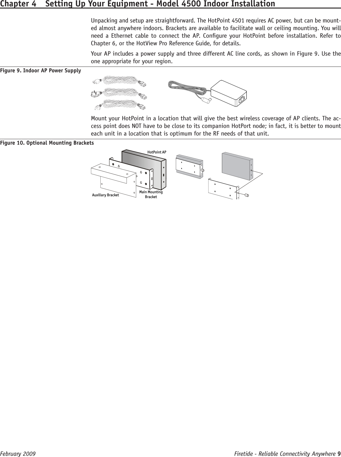
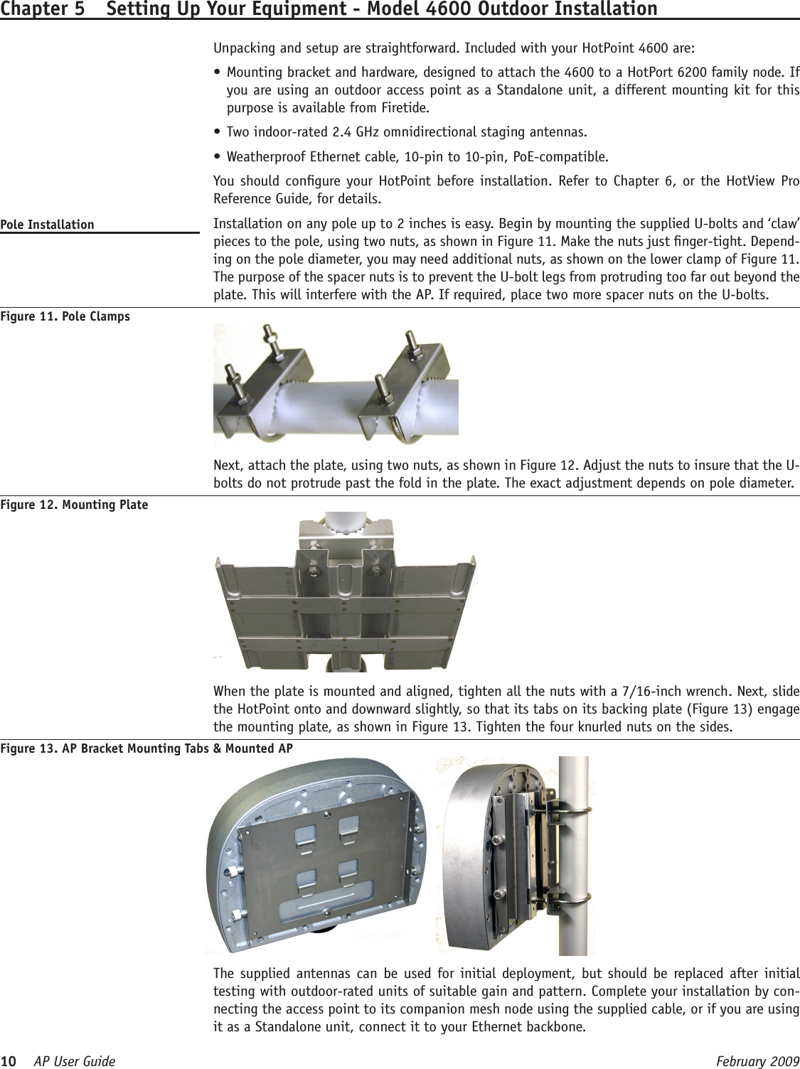
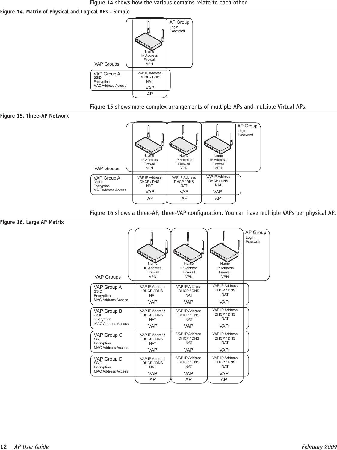
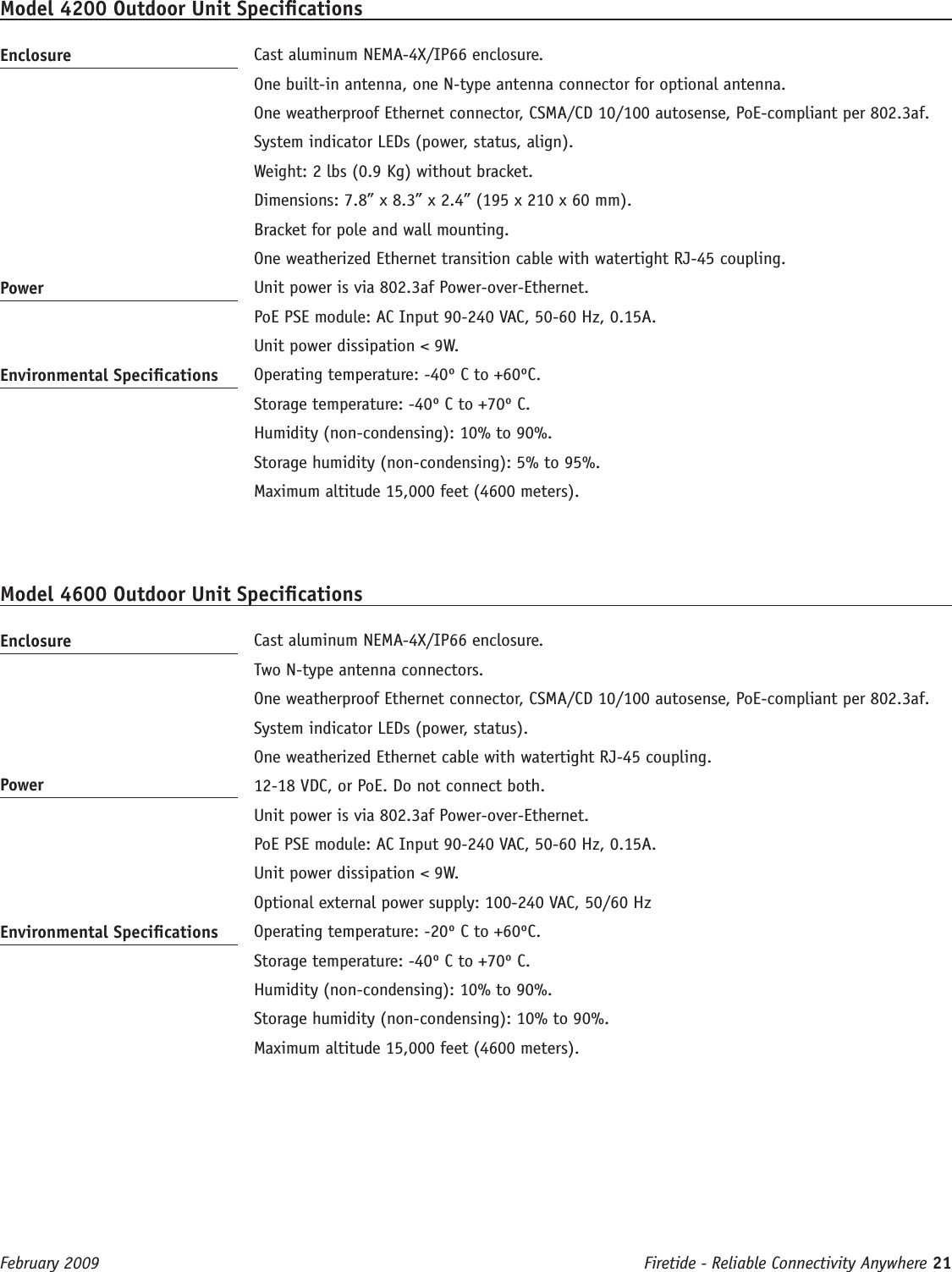
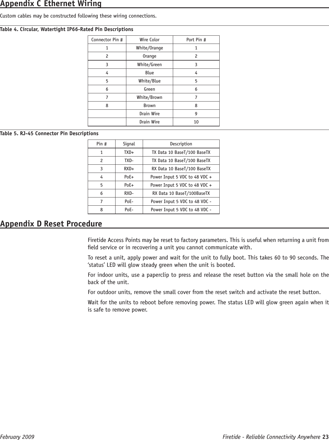
4100 User Guide
2.
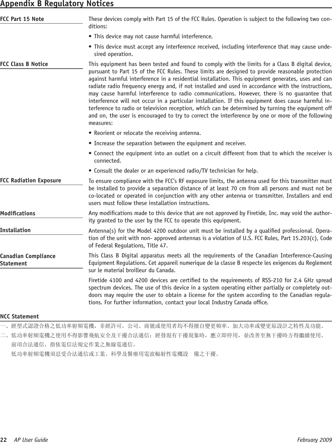
User Manual
4100 User Guide
Navigation menu
Upload a User Manual
Namespaces
Wiki Guide
HTML
PDF
Info
Views
User Manual
Discussion / Help
Navigation