Firetide 5900-1 5900 Mesh Node User Manual 5900 HotViewPro Manual 3 Part 2
Firetide Inc. 5900 Mesh Node 5900 HotViewPro Manual 3 Part 2
Firetide >
Contents
- 1. 5900_HotViewPro_Manual_3 Part 1
- 2. 5900_HotViewPro_Manual_3 Part 2
- 3. Quick Installation Guide
- 4. User Manual Part 1
- 5. User Manual Part 2
5900_HotViewPro_Manual_3 Part 2
Enabling Radios & MIMO Operation 37
6 Enabling Radios & MIMO Operation
Aclara 5900 Series nodes ship with one 900 MHz radio and one radio ca-
pable of operation on 2.4, 4.9, or 5 GHz. This multi-band radio can be
upgraded to 802.11n (MIMO operation, if desired. (The 900 MHz radio
does not support MIMO.)
Firetide HotPort 7000 Series nodes used as part of the STAR system can be
ordered with a single 900 MHz radio, or a dual radio configuration similar
to the Aclara 5900.
In either case, you may need to use a software license key to active the sec-
ond radio, or activate the MIMO option. This chapter explains how.
Meshes which have some nodes enabled for 802.11n will use this mode
between themselves, but will communicate with other nodes in the mesh
using 802.11a or g.
You must purchase license keys and enter them into the Licensing tab of the
HotView Pro Server Configuration screen. Request a Permanent License
and import it before beginning node upgrade. If you are not familiar with
the process, refer to the software installation reference guide for details.
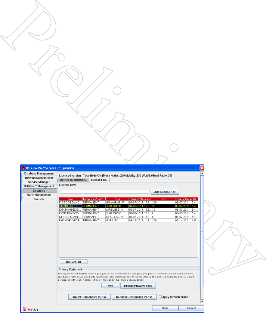
Figure 5.46 shows the licensing tab for a server that has had several dual-
radio and Wireless-N (MIMO) licenses added. To upgrade a node, begin by
selecting the type of upgrade you wish to perform. This example shows a
dual-radio upgrade. Next, click on the HotPort List button.
Figure 5.46 eNAbliNg The SecoNd
rAdio
Select the license type for the type of
upgrade you wish to perform - Dual
Radio or Wireless-N.
38 HotView Pro Software Operation
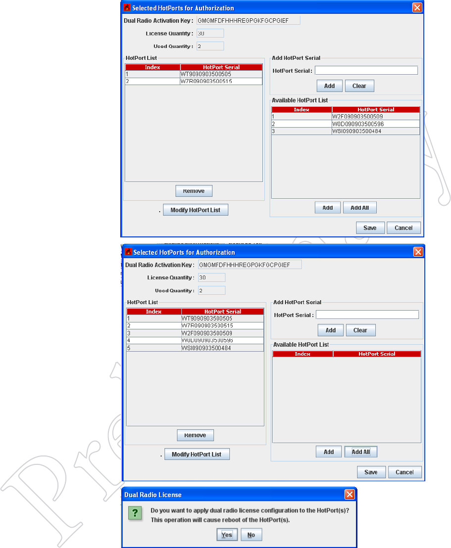
Figure 5.47 SelecTiNg NodeS To
upgrAde
The left side of the screen shows the
nodes that have already been up-
graded. The right side shows nodes
available for upgrade.
To upgrade a node on the right, select
it and click on Add.
If the node you wish to upgrade does
not appear, cancel and trouble-shoot
the problem. A node must be con-
nected to be upgraded.
Figure 5.48 reAdy For upgrAde
The nodes to be upgraded have been
added to the left side. Click Save. You
will see a confirmation dialog. Click
Yes to proceed.
Second-radio upgrades and 802.11n
upgrades are permanent. Make sure
you are upgrading the correct nodes.
MIMO Upgrades
802.11n (MIMO upgrades) are performed the same way.

Keeping the Mesh Secure 39
7 Keeping the Mesh Secure
By default, a Firetide mesh is open; this makes initial configuration easy.
Most applications, however, will want a higher level of security. Firetide
offers a number of features that allow you to implement various levels of
security. These security features fall into three categories:
• Radio security
• Mesh connection security
• User security
Firetide HotPort 7000 Series nodes are FIPS 140 compliant. Both the
HotPort 7000 Series and HotPort 6000 Series nodes are FIPS 180-3, FIPS
186-2, and FIPS 197 compliant.
Radio Security
Successful eavesdropping can be prevented by enabling 256-bit AES en-
cryption over the radio links. An additional end-to-end encryption layer
can also be added, if desired.
The ESSID can be encrypted, in order to keep casual eavesdroppers from
detecting equipment presence
Mesh Connection Security
Normally, a node will join a mesh if the basic mesh settings are the same.
To prevent unknown nodes from joining the mesh, you must change the
default mesh settings.
You can also disable unused Ethernet ports (or ones in use, for that matter),
and also set alarms to detect a change in state of any port. This prevents the
connection of unauthorized equipment.
If desired, you can restrict mesh traffic to that traffic which originates on a
pre-defined set of Ethernet MAC addresses. This is a powerful, but some-
what tricky tool.
For ultra-high security applications, you can enable a feature which uses
digital signatures to prevent a mesh node from joining a mesh until it is
explicitly approved to do so.
User Security
All security is worthless if unauthorized users can access HotView Pro itself
and modify settings. HotView Pro permits to define multiple levels of user
access and authority.
40 HotView Pro Software Operation
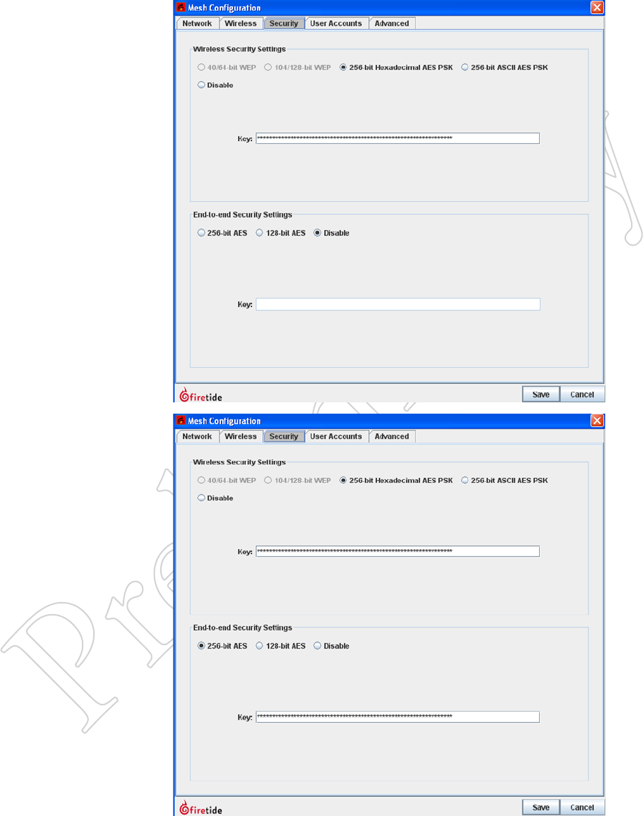
Figure 6.49 eNAbliNg rAdio
eNcrypTioN
Over-the-air traffic should be en-
crypted using the built-in 256-bit AES
encryption engine.
Select either hex or ASCII key formats,
and enter the key string.
The encryption is performed in
hardware, and there is no measurable
performance impact.
Figure 6.50 eNd-To-eNd eNcryp-
TioN
You can enable a second level of
encryption for the maximum possible
security; however this can imposes a
small throughput penalty on very fast
links (>50 Mbps) on HotPort 7000
Series nodes.
Radio Security
Keeping the Mesh Secure 39
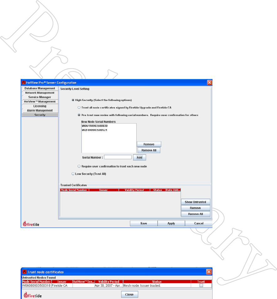
Figure 6.51 high SecuriTy Mode
When High Security is selected, you
have three options: trust all; pre-trust
existing, and require confirmation for
all.
For the pre-trust option, you must
enter the serial numbers for each exist-
ing node.
Mesh Connection Security
Mesh Connection security covers all of the available techniques used to pre-
vent an intruder from either adding a node to the mesh, or making a wired
Ethernet connection to an existing mesh node. There are several facets to
mesh intrusion prevention. These are:
Blocking Unauthorized Nodes
In even the simplest, low-security applications, you should always change
the basic mesh parameters: mesh ID number, mesh name, mesh IP address,
and mesh ESSID. You should also enable radio encryption.
You can prevent unauthorized nodes from joining the mesh. To do this, you
must enable the high security mode in HotView Pro. Note that this is sys-
tem-wide; you cannot have some meshes at high security and other meshes
at low security. Figure 6.51 shows the Security tab within the HotView Pro
Server Configuration window. High Security has been selected.
Typically, a mesh is configured and deployed before high-security is en-
abled; this is much simpler. Once the system has been deployed and is ready
to be placed into production service, high security is enabled and the serial
numbers are entered manually, as shown in Figure 6.51.
Figure 6.52 AddiNg A TruSTed
Node
When a new node attempts to join the
mesh, a dialog window will appear,
requesting permission.
42 HotView Pro Software Operation
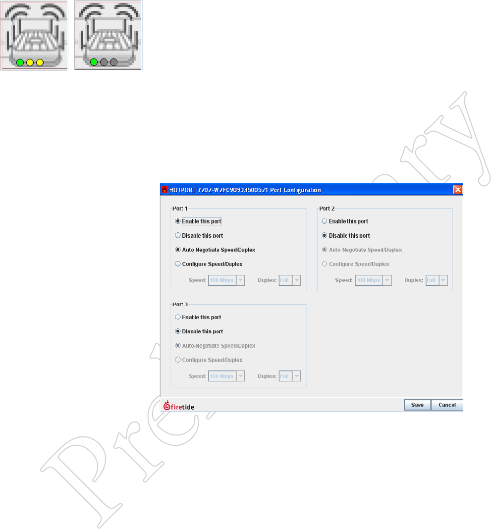
Figure 6.53 AcTive ANd diSAbled
eTherNeT porTS
The icon on the left shows an outdoor
node with one port in use (green) and
two active, but unused ports (yellow).
On the right, the two unused ports are
gray - they have been disabled.
Limiting Unauthorized Connections
It is possible for unauthorized users to attach equipment to the existing
mesh. There are two steps you can take to prevent this:
• Disable unused Ethernet ports.
• Create an automatic alarm/e-mail alert if an Ethernet port is tampered
with.
The status of every port on the mesh is visible on each node, as shown in
Figure 6.53. Disabled ports are just that; disabled - if you connect to one,
it will not respond in any way. (This can be a source of frustration when
troubleshooting a problem. If a connection does not seem to be working,
check to be sure the port is enabled.)
To disable (or re-enable) an Ethernet port, right-click on the node and
select Configure Node Port > Port Configuration. Then modify the port
settings as desired.
Figure 6.54 diSAbliNg porTS
Individual Ethernet ports may be
disabled, as shown.
Port Change Alarms
An intruder could still potentially gain access to the mesh by unhooking
an existing devices, such as a camera or access point, and connecting in its
place. This cannot be prevented (except by physical means) but it can be
detected, using Hot View Pro’s alarm capability. Refer to the chapter on
alarms to learn how to trigger an alarm on any change of state of any wired
Ethernet port.
Keeping the Mesh Secure 39
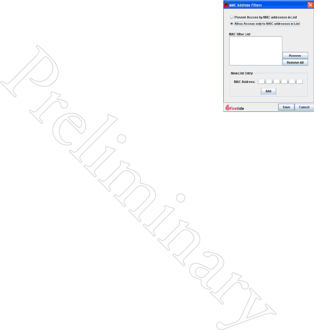
MAC Address Filtering
MAC Address Filtering is a powerful but dangerous tool. It simply blocks
all Ethernet frames from traversing the mesh, except those which have a
permitted source MAC address.
It is critical to make sure that ALL necessary MAC addresses are added to
the list; in particular the MAC address of the HotView Pro server and/or
any intervening switches, routers, or other equipment. Failure to do so will
cut you off from the mesh; you will need to factory-reset all nodes in order
to recover. It’s best to include the MAC addresses of one or two ‘spare’ ma-
chines on site, just is case a problem develops with the primary HotView
Pro machine.
The MAC Address filtering command can also be used to block specific
MAC addresses. This has limited security use, but can be helpful in dis-
abling any misbehaving hardware on the mesh.
Figure 6.55 MAc AddreSS
FilTeriNg
Use this window to enter the MAC
addresses to be permitted on the mesh.
Be sure to include the address of the
HotView Pro server.
44 HotView Pro Software Operation
User Security
It is also necessary to limit human access to the mesh; in particular to Hot-
View Pro. This is a multi-step process. You must:
• Re-define the login credential that is used to access the mesh itself.
• Define user login credentials for each human user.
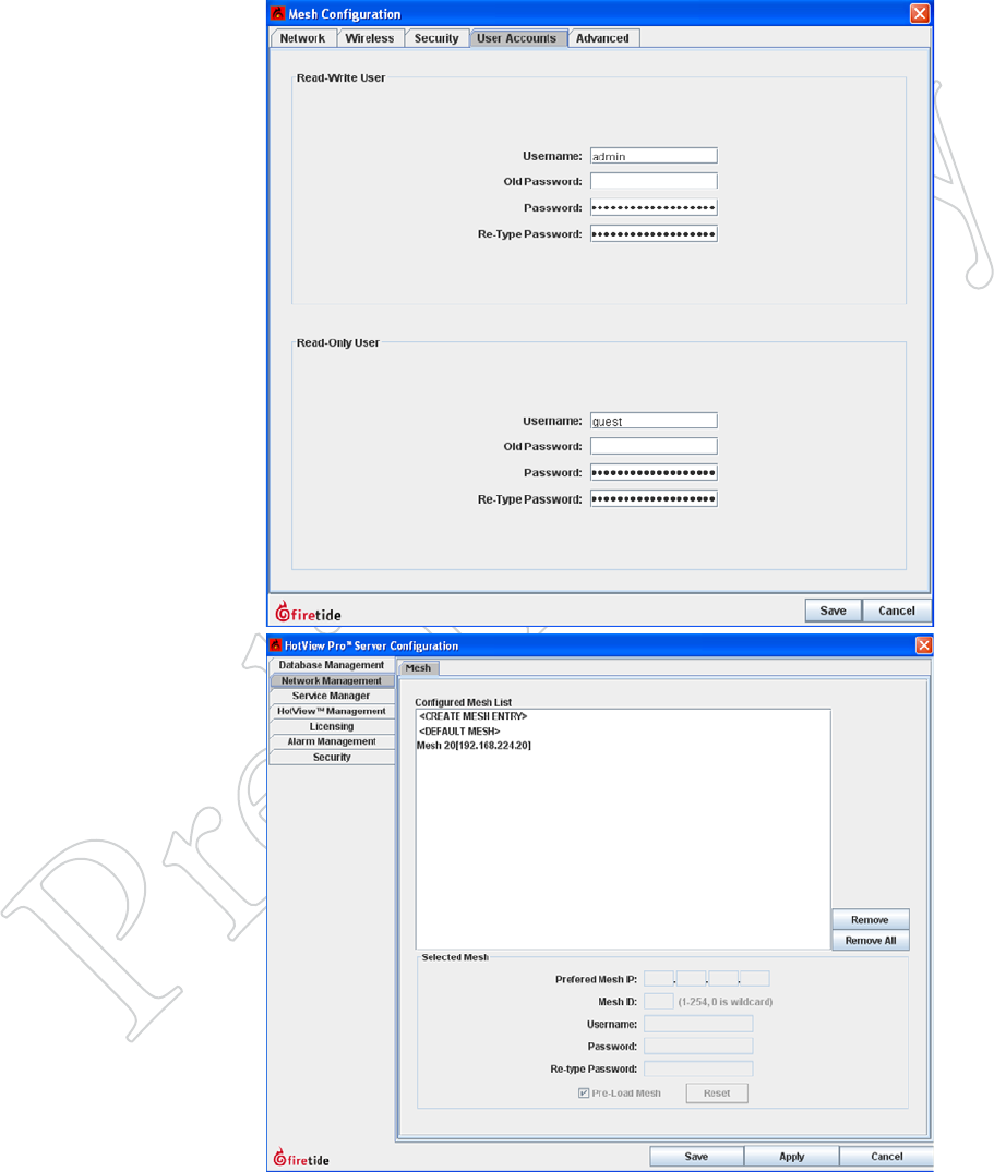
Figure 6.56 MeSh logiN credeN-
TiAl - MeSh
HotView Pro connects to the mesh
using the mesh’s User Account login
credential, shown here.
You should change the Read/Write
user name and password. The default
values are admin and firetide.
Figure 6.57 MeSh logiN credeN-
TiAl - hoTview pro Server
After changing the mesh login creden-
tial on the mesh itself, you must tell
HotView Pro what the new credential
is. Do so via the HotView Pro Server
Configuration menu, as shown.
Keeping the Mesh Secure 39
Dening Human Users
Human users of HotView Pro are defined as part of HotView Pro Server
Configuration. Two default users are pre-defined, hv_admin and hv_guest.
The default user hv_admin has full privileges on all meshes and system ad-
ministration privileges; the default user hv_guest is read-only.
There are three assignable privileges for each user:
• Server Configuration Granting this privilege allows the user to config-
ure the HotView Pro Server, and add other users. This is
effectively a super-user level. Options are deny access or
admin access.
• Default Access This parameter defines the access level given
to the user for all new meshes created; that is, ones not
already shown in the mesh list. Options are: deny access,
read-only, or read-write.
• Access Privileges This parameter lets you specify the access level
for each existing mesh, controller, and AP groups. Op-
tions are: deny access, read-only, or read-write.
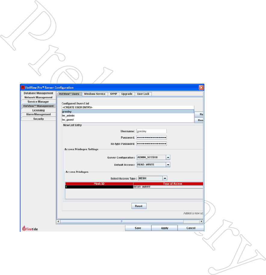
Figure 6.58 uSer deFiNiTioNS
Users can be assigned different
privilege levels on a mesh-by-mesh
basis. This provides a high degree of
flexibility, especially in multi-tenancy
applications.
Here, a new user (grenley) has been
created, and has been assigned admin-
istrative access to HotView Pro, as well
as read-write access to all current and
future meshes.
When creating all-access user accounts
be sure to use the Select Access Type
drop down to assign read-write access
for Controllers and AP Groups as well.
46 HotView Pro Software Operation
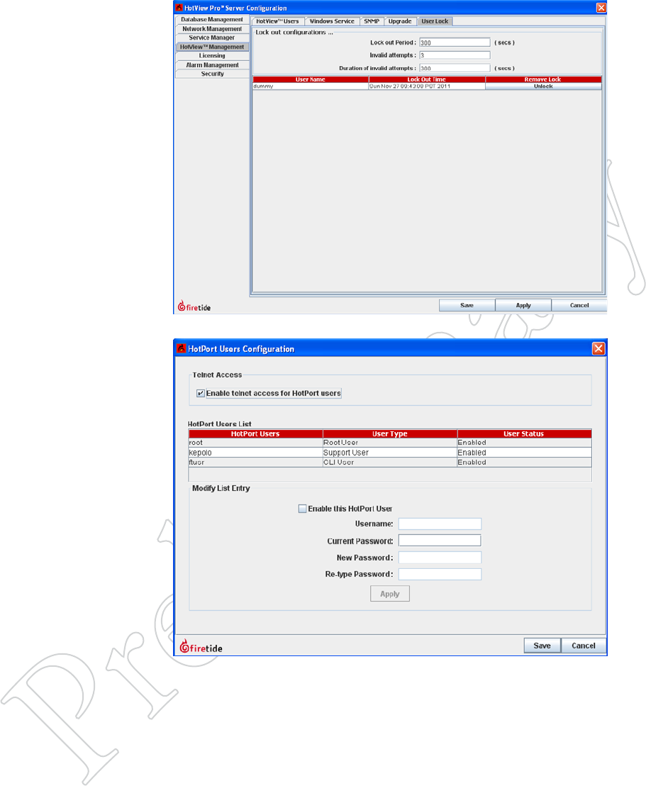
Figure 6.59 uSer lockouT
In high-security mode, you can specify
a maximum number of login attempts.
Exceeding this level will lock the user
out. The user will remain locked out
for the lockout period. If this is set to
0, the user will be locked out until he
is manually unlocked.
Figure 6.60 reMoTe AcceSS uSer
coNFigurATioN
HotView Pro allows remote access
via telnet or SSH to each node in the
mesh. The access credentials for this
should be either disabled or changed.
Use HotPort Users Configuration,
under the Mesh menu, to do this.
Conguring an Ethernet Direct Connection 47
8 Conguring an Ethernet Direct Connection
An Ethernet Direct connection is a wired connection between two nodes in
the same mesh. (There can be wired connections between meshes, but these
are not Ethernet Direct.) Ethernet Direct is commonly used between nodes
that are relatively close together, but may not be in RF contact. Typically
this occurs with nodes which are mounted on a building roof or tower, and
use direction antennas to cover the landscape.
The mesh treats an Ethernet Direct as if it were simply another radio link
between nodes. Ethernet Direct offers three advantages:
• It is faster than a radio link - nominally 1 Gbps.
• It is full-duplex; radios are half-duplex.
• It does not tie up spectrum or radios; allowing them to continue to
carry other traffic.
Setting up an Ethernet Direct is easy. Begin by selecting the Ethernet Direct
option from the Mesh menu. A window appears. You will use this window
to define a tunnel that will carry the traffic between the nodes.
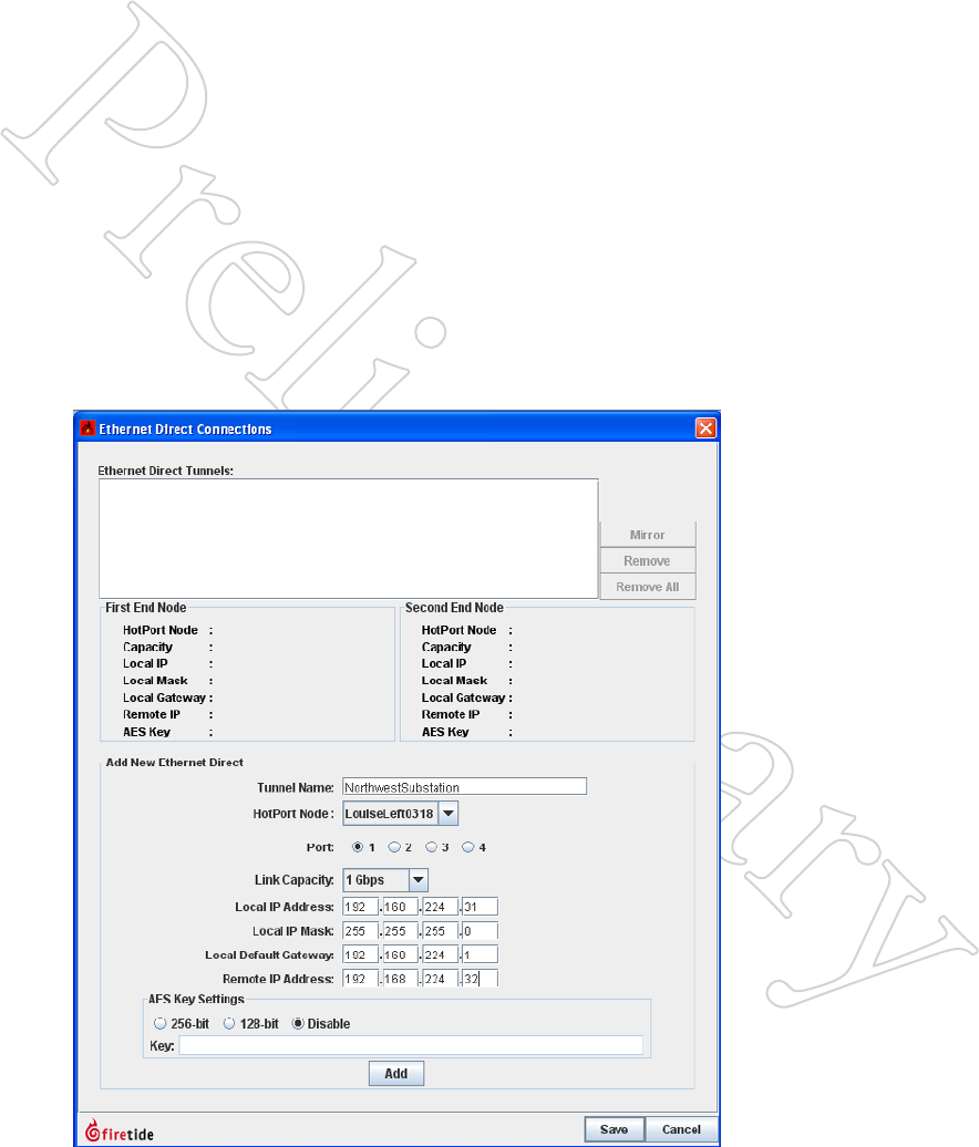
Figure 7.61 eTherNeT direcT -
iNiTiAl dATA eNTry
Begin by entering a name for the
Ethernet Direct tunnel; then select the
node from the drop-down list of nodes
on the mesh. Select the wired port
that you will use. DO be sure to pick
the Ethernet port you plan to use. It
is common to use port 1, because this
is the non-PoE port. This leaves the
PoE port available for cameras, APs, or
other equipment.
DO NOT connect a wire between the
nodes. That is the last step.
You’ll need to create two tunnel end-
point IP address for this. They must
be unique; typically two values are
selected from the same subnet.
Enter the selected tunnel IP address
information, and specify the link
capacity. A correct link capacity helps
the mesh load balance better.
The link can be encrypted if necessary.
Finally, click Add, but do NOT click
Save.
48 HotView Pro Software Operation
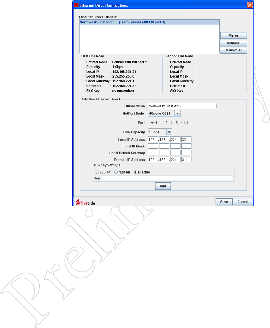
Figure 7.62 FAr-eNd TuNNel
eNdpoiNT
At the top of the window, select the
blue text - this is the first tunnel
endpoint. It will highlight, as shown.
Click on mirror. The IP addresses at
the bottom fill in, but are reversed for
near and far ends.
Select the node for the other end of
the tunnel, and select the port.
Next, fill in the subnet mask and de-
fault gateway, then click add again.
Conguring an Ethernet Direct Connection 47
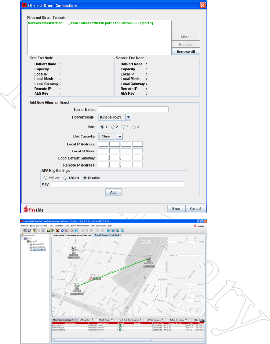
Figure 7.63 coMpleTed TuNNel
When you have completed the data
entry for both ends of the tunnel, and
clicked Add, the tunnel text will turn
green. It is now time to click Save.
It is also time to complete the wired
connection between the two nodes.
Make sure you complete the wired
connection to the ports shown in the
Ethernet Direct tunnel listing.
Figure 7.64 coMpleTed eTherNeT
direcT
A green line will appear between the
nodes when the Ethernet Direct con-
nection is operating correctly.
50 HotView Pro Software Operation
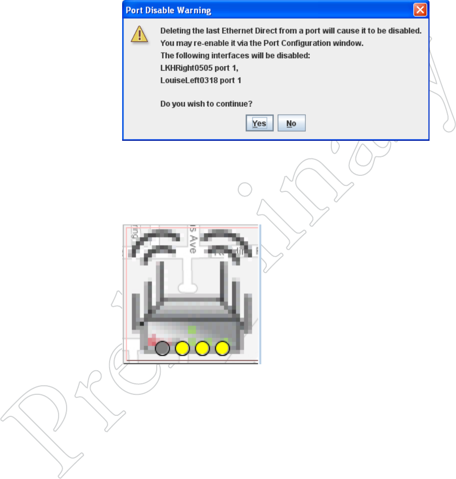
Figure 7.65 eTherNeT direcT
porT diSAble wArNiNg
When you tear down an Ethernet
Direct connection, the ports involved
will be disabled.
Figure 7.66 diSAbled porT
iNdicATioN
A node with a disabled Ethernet port
will show a gray dot, instead of a yel-
low (enabled) or green (in use) dot.
Tearing Down an Ethernet Direct Connection
If the Ethernet Direct connection is not needed, it can easily be removed.
Simply go to the Ethernet Direct setup window via the Mesh menu, select
the tunnel to be removed, and click on Remove. You will see a warning
message.
Remove the wired connection, if you have not done so already. Then re-
enable the Ethernet ports. This is done by right-clicking on each node and
selecting the Port Configuration command.
Creating Gateway Groups 51
9 Creating Gateway Groups
Gateway groups provide redundant, load-balancing connections between a
wireless mesh and the wired infrastructure.
There are two key elements in a Gateway Group: the Gateway Interface
nodes and the Gateway Server.
The Gateway Interface nodes act as the gateways between the wireless world
and the wired world. There are at least two, for redundancy, and there can
be as many as eight. Gateway interface nodes are 5900 series nodes.
The Gateway Server is the controlling device for all Gateway Interface
nodes. It manages the traffic, load-balances, and is responsible for broad-
cast and multicast containment. The Gateway Server node must be a 7000.
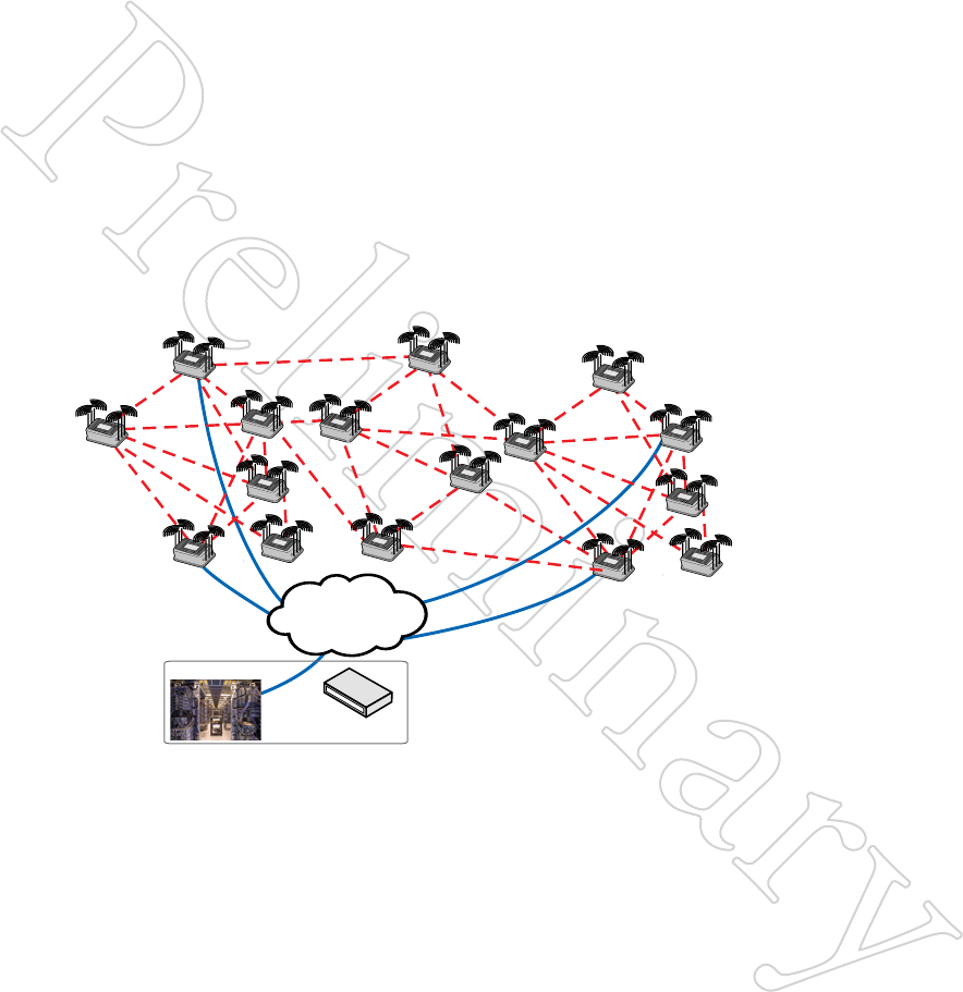
Figure 8.67 bASic gATewAy
group
The Gateway Group consists of the
Gateway Server, located in a safe,
benign environment, and the Gateway
Interface nodes, located in the field as
part of the mesh.
In this example, there are four
Gateway Interface nodes positioned
throughout the mesh.
Logically, the Gateway Group consists of tunneled connections between
the Gateway Interface nodes and the Gateway Server. Setting up a Gateway
Group consists primarily of creating these tunnels.
Note: the Gateway Server is a single point of failure in the system, so it
should be installed in a computer or server room, backed up by a UPS. It is
possible to configure a redundant backup Gateway Server, if desired.
Gateway Server
Wired
Network
Server Room
HotPort
Mesh
Gateway
Interface Node
Gateway
Interface Node
Gateway
Interface Node
Gateway
Interface Node
52 HotView Pro Software Operation
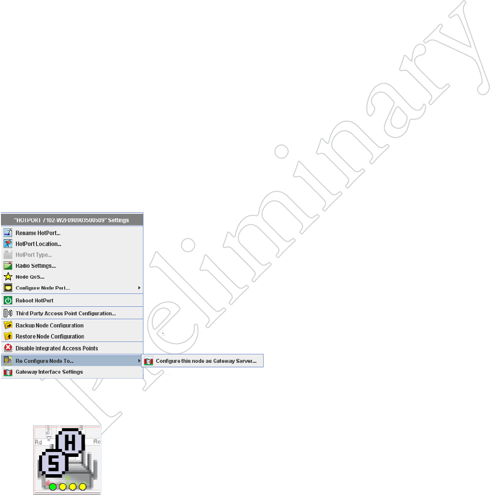
Figure 8.68 creATiNg A gATewAy
Server Node
Right-click on the node you wish to
re-configure, and select the Configure
this node as a Gateway Server...
Steps to Create a Gateway Group
There are seven basic steps involved in creating a Gateway Group.
1. Use the Import Mesh Configuration command to make a current
copy of the mesh configuration for the mesh to which you are adding
the Gateway Group.
2. Using a new node, switch its operated mode from normal operation to
Gateway Server.
3. Tell this new Gateway Server node which mesh it is to be the Gateway
Server for.
4. Configure the tunnel IP addresses and other key information in the
Gateway Server.
5. Manually configure one node, already on the mesh, to be a Gateway
Interface node.
6. Disconnect the existing mesh connection; connect the new Gateway
Interface node and the Gateway Server node together via a switch.
7. Now that the Gateway Server is talking to the mesh, instruct it to
inform the other Gateway Interface nodes of the relevant tunnel pa-
rameters.
Each of these basic steps consist of several sub-steps.
STep 1: impoRT The meSh CoNfigURATioN
Import the current mesh configuration from the current mesh, and save the
file where you can find it later. Log out of the mesh and physically discon-
nect from it.
STep 2: SwiTChiNg The opeRATiNg mode of A Node
Set up a new (or otherwise unused) node on the bench, and apply power.
After one minute or so, it should respond to pings at 192.168.224.150. If
it doesn’t, reset it with a paperclip or similar.
Using HotView Pro, connect to this one-node “mesh” at 192.168.224.150.
If a Country Code warning appears, you can ignore it.
Figure 8.69 gATewAy Server icoN
If you did the reconfiguration right, it
will look like this:
Right-click on the node, and select Re-Configure this Node to... and select
the flyout Configure This Node as a Gateway Server.
You will see a warning message; then the node will reboot. Log out of the
mesh.
The node IP address will still be 192.168.224.150. When the reboots, use
the Add Mesh command to re-connect to the node.
Creating Gateway Groups 53
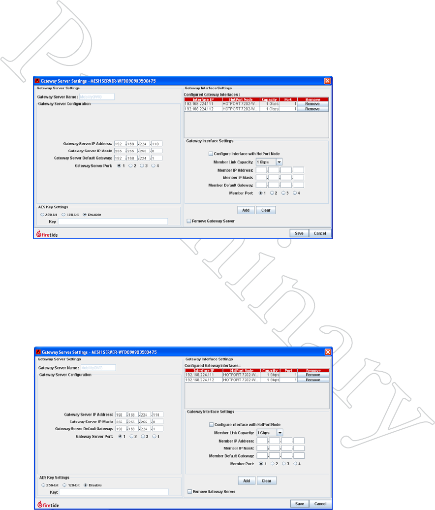
Figure 8.70 gATewAy Server SeT-
TiNgS, pArT oNe
This window lets you configure all
tunnel IP addresses and other key
parameters for the Gateway Group.
In this example, the Gateway Group
has been named, and the IP address
for the Gateway Server end of the tun-
nels has been entered.
Figure 8.71 gATewAy Server SeT-
TiNgS, pArT Two
Here, two sets of tunnel IP addresses
have been entered, simply by typing
them in and clicking on the Add but-
ton. There is no need (yet) to worry
about which Gateway Interface node
gets which tunnel address.
You can have up to 16 Gateway Inter-
face nodes, and you can enter all the
addresses now, if you wish.
STep 3: Tell The New gATewAy SeRveR Node whiCh meSh iT iS The
gATewAy SeRveR foR
Use the Apply Saved Mesh Configuration command to do this. Note: it is
a common error to skip this step; the Gateway Group will not work if you
have not done this. Note that this will change the Mesh IP address; you will
need to log out of the mesh, and then add the mesh back at the new address.
STep 4: CoNfigURe The TUNNel ip AddReSSeS ANd oTheR iNfoRmATioN
Right-click on the Gateway Server node and select Gateway Configuration.
From the flyout menu, select Gateway Server Settings.
Begin by configuring the Gateway Server tunnel IP addresses, in the left
half of the window, as shown in Figure 8.70.
Next, on the right side of the window, enter the IP addresses for the tunnel
endpoints that will terminate at the Gateway Interface nodes (referred to
here as members).
The Member Link Capacity drop-down lets you specify the data rate of the
connection between the Gateway Interface node and the wired backbone.
While the nodes themselves operate at 1 Gbps, the backhaul link may be
slower. Setting the link capacity helps the Gateway Server do a better job
of load balancing.
54 HotView Pro Software Operation
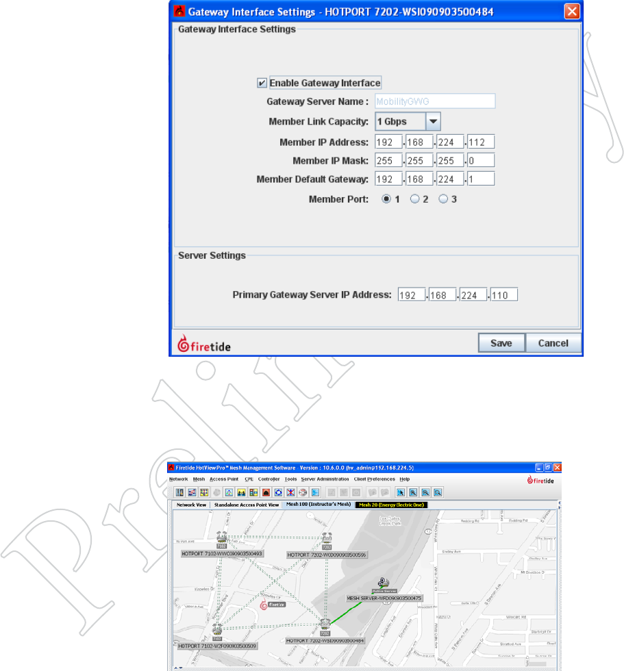
Figure 8.72 gATewAy iNTerFAce
SeTTiNgS
Tick the Enable Gateway Interface
box, and enter the tunnel IP address in
the Member IP address field. Com-
plete the other fields, including the
port to be used.
Next, enter the Gateway Server tunnel
IP address in the field at the bottom.
Click Save.
Figure 8.73 FirST gATewAy group
liNk up
If you did everything correctly, there
will be a solid green line between the
Gateway Server node and the Gateway
Interface node.
STep 5: mANUAlly CoNfigURe The fiRST gATewAy iNTeRfACe Node
Log out of the one-node Gateway Server “mesh”, and physically disconnect
from it. Physically connect to the original mesh again. Use the Add Mesh
command to re-connect to it.
Right-click on one of the nodes that will be a Gateway Interface node, but
is NOT the current head node.
STep 6: SwiTCh The wiReS ARoUNd
Log out of the mesh. Disconnect the wire from the head node to the switch.
Connect the Gateway Server node to the switch, then connect the Gateway
Interface node you just configured to the switch. Use the Add Mesh com-
mand to re-connect to the mesh. It should look like Figure 8.73
Creating Gateway Groups 55
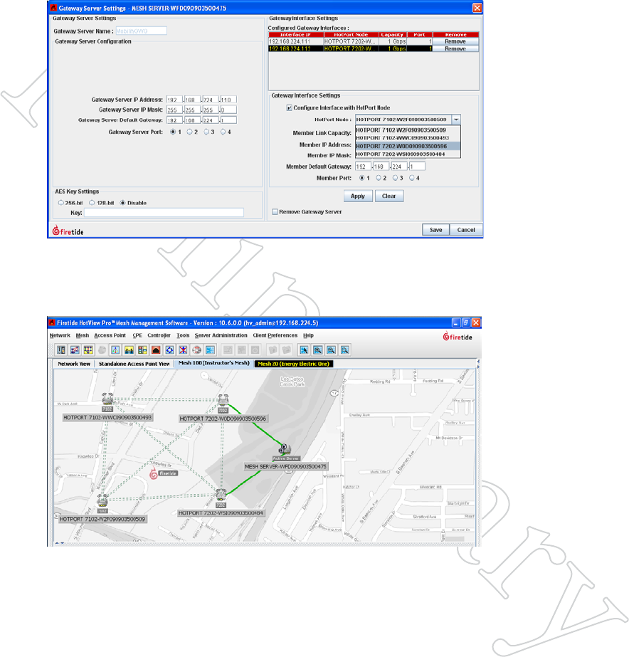
STep 7: gATewAy SeRveR CoNfigUReS The gATewAy iNTeRfACe NodeS
Now that the Gateway Server is in communication with the mesh, it can
automatically configure other Gateway Interface nodes. To tell it to do so,
right-click on the Gateway Server node and bring up the Gateway Server
Configuration window. Note that one of the Gateway Interfaces is already
configured, but the others are not.
Figure 8.74 gATewAy Server
SeTTiNgS
Select the Gateway Interface that is
not yet configured, and tick the box
below it that says Configure Interface
with HotPort WAN Node.
Select the desired node from the drop-
down that appears. Click Apply.
Repeat as required, then click Save.
When you have completed configuring the remaining Gateway Interface
nodes, connect them to the switch. When you are done, your mesh should
look like Figure 8.75.
Figure 8.75 coMpleTed gATewAy
group
This shows a typical Gateway Group
with two Gateway Interface nodes.

56 HotView Pro Software Operation
Multicast 57
10 Multicast
Multicast is a layer-3 protocol widely used for audio and video distribution.
It is also used for various zero-configuration protocols, such as Bonjour.
Multicast, while a layer-3 protocol, also affects layer 2, because it uses a spe-
cial range of Ethernet MAC addresses. Certain characteristics of the 802.11
family of wireless protocol are affected by these addresses, so it is neces-
sary to either block all multicast traffic or configure your Firetide mesh to
handle Multicast traffic with maximum efficiency.
Briefly, Multicast packets have an IP address in the range of 224.0.0.0 to
239.255.255.255. These packets will be carried in Ethernet frames with
MAC addresses in the range of 01:00:5E:00:00:00 - 01:00:5E:7F:FF:FF.
Further details on Multicast addressing can be found at the end of this
chapter.
mUlTiCAST ANd 802.11 wiReleSS pRoToColS
Multicast presents a challenge for a wireless access point, because the AP
does no have a good way of know which client is the intended recipient,
or how good the wireless connection is. The 802.11 standards committee
elected to simplify this problem by requiring the radio to slow down to its
lowest modulation rate (e.g. 6 Mbps for 802.11g) and send the Ethernet
frame to all clients. This is simple and reliable but not very efficient. It
means that the entire mesh will slow down, dramatically, even if there is
only a modest amount of Multicast traffic.
To preserve maximum wireless speed, Firetide offers an option to encapsu-
late Multicast traffic inside conventional Unicast frames, which can then be
sent precisely where they need to be at full radio speed.
Firetide also offers an option to simply block all multicast traffic. Many
installations do not require support for Multicast traffic across the mesh;
this option is a simple solution.
Systems which must support Multicast need to create one or more Multicast
Groups.
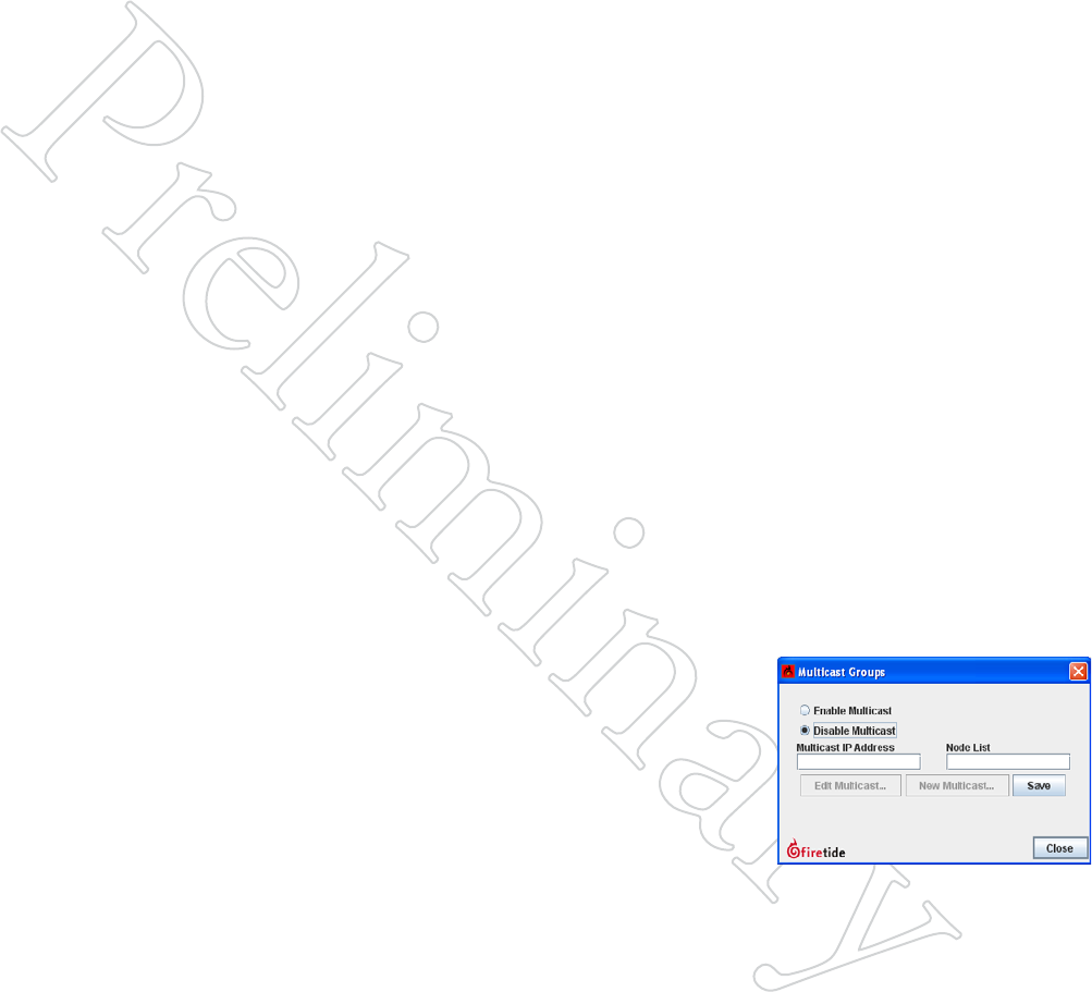
Figure 9.76 diSAbliNg MulTicAST
If your network does not require
Multicast support (and many don’t)
you should disable Multicast. This can
be done by clicking on the Mesh menu
and selecting Multicast Groups.
58 HotView Pro Software Operation
Creating a Multicast Group
First, determine which Multicast IP addresses will be in use on the mesh.
It is possible to configure the system to allow all Multicast, but this may
not give the same performance if there is ‘random’ Multicast traffic present.
You should also identify the nodes which represent the source of the Mul-
ticast traffic (typically the camera nodes) and the destination (usually the
head node or the Gateway Interface nodes.
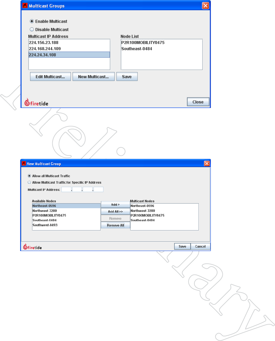
Once you have identified the Multicast IP addresses to be used, select the
Multicast Groups command from the mesh menu, and the click on New
Multicast.
This opens a window in which you can specify the IP address and the nodes
which need to participate. You will create a Multicast Group for each Mul-
ticast IP address in use.
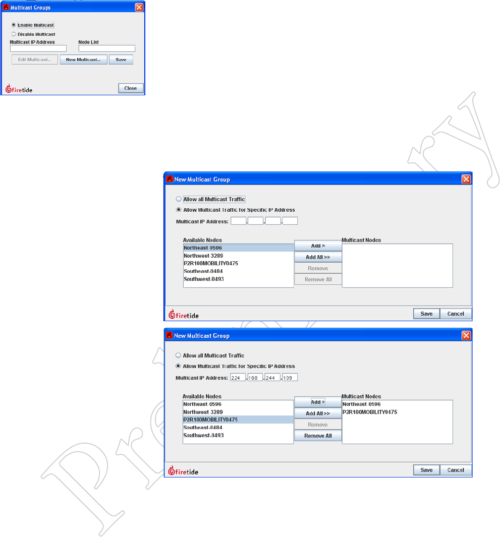
Figure 9.77 creATiNg A MulTi-
cAST group
Figure 9.78 New MulTicAST
wiNdow
Here, you can specify the IP address
for the Multicast group, and add the
required nodes to the group.
Figure 9.79 A coMpleTed MulTi-
cAST group
The exit node and the source node
for this IP Multicast group have been
added.
Repeat this process for each Multicast group you plan to use. An example of
a multiple-Multicast setup is shown in Figure 9.80.
Multicast 57
Figure 9.80 coMpleTed MulTi-
cAST groupS
Here, three Multicast groups have
been defined.
Allowing All Multicast
You can also allow all Multicast traffic to or from either all nodes, or a
subset thereof. This is recommended only if you do not know what the
Multicast IP address groups will be.
Removing a Multicast Group
To remove a Multicast group, select Edit Multicast and remove all the nodes
from the group.
Figure 9.81 AllowiNg All MulTi-
cAST TrAFFic
This can include all nodes, or a se-
lected subset.

60 HotView Pro Software Operation
IP Address Reserved Function
224.0.0.0 Base address (reserved)
224.0.0.1 All Hosts multicast group addresses all hosts on the same network segment.
224.0.0.2 All Routers multicast group addresses all routers on the same network segment.
224.0.0.4 Used in the Distance Vector Multicast Routing Protocol (DVMRP) to address multicast routers.
224.0.0.5 All OSPF Routers address is used to send Hello packets to all OSPF routers on a network segment.
224.0.0.6 All D Routers address is used to send routing information to designated routers on a segment.
224.0.0.9 RIP version 2 group address is used to send routing information to all RIP2-aware routers on a segment.
224.0.0.10 EIGRP group address is used to send routing information to all EIGRP routers on a network segment.
224.0.0.13 Protocol Independent Multicast (PIM) Version 2
224.0.0.18 Virtual Router Redundancy Protocol (VRRP)
224.0.0.19 - 21 IS-IS over IP
224.0.0.22 Internet Group Management Protocol (IGMP) Version 3
224.0.0.102 Hot Standby Router Protocol version 2 (HSRPv2) / Gateway Load Balancing Protocol (GLBP)
224.0.0.107 Precision Time Protocol version 2 peer delay measurement messaging
224.0.0.251 Multicast DNS (mDNS) address
224.0.0.252 Link-local Multicast Name Resolution (LLMNR) address
224.0.1.1 NTP clients listen on this address for protocol messages when operating in multicast mode.
224.0.1.39 AUTO-RP-ANNOUNCE address is used by RP mapping agents to listen for candidate announcements.
224.0.1.40 AUTO-RP-DISCOVERY address is destination address for RP mapping agent to discover candidates.
224.0.1.41 H.323 Gatekeeper discovery address
224.0.1.129 - 132 Precision Time Protocol version 1 time announcements
224.0.1.129 Precision Time Protocol version 2 time announcements
224.0.1.133-
239.255.255.255
Available for Multicast Groups
Ethernet multicast address Type Field Usage
01-00-0C-CC-CC-CC 0x0802 CDP (Cisco Discovery Protocol), VTP (VLAN Trunking Protocol)
01-00-0C-CC-CC-CD 0x0802 Cisco Shared Spanning Tree Protocol Address
01-80-C2-00-00-00 0x0802 Spanning Tree Protocol (for bridges) IEEE 802.1D
01-80-C2-00-00-08 0x0802 Spanning Tree Protocol (for provider bridges) IEEE 802.1AD
01-80-C2-00-00-02 0x8809 Ethernet OAM Protocol IEEE 802.3ah
01-00-5E-xx-xx-xx 0x0800 IPv4 Multicast (RFC 1112)
33-33-xx-xx-xx-xx 0x86DD IPv6 Multicast (RFC 2464)
Figure 9.82 reServed AddreSSeS
These tables show the reserved ad-
dresses used for various Multicast
functions and Ethernet MAC address-
es. This information may be of use in
troubleshooting Multicast problems.
VLANs 61
11 VLANs
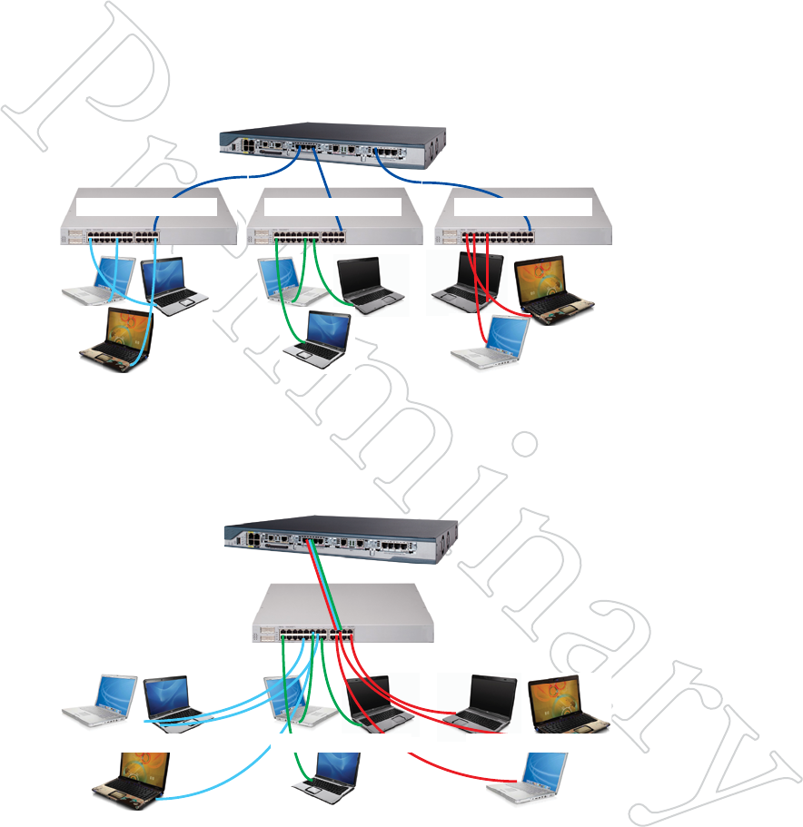
Virtual LANs are created to provide segmentation and isolation services
that would otherwise be implemented using physically-distinct Ethernet
switches, with routers as the sole interconnect between LAN segments.
Figure 10.83 shows three subnets, each isolated by virtue of being on its
own switch. A router interconnects them. This provides the desired traf-
fic isolation and security, but it is inflexible because it is implemented in
hardware.
Subnet 192.1.24.0/24 Subnet 10.13.54.0/24Subnet 172.1.1.0/24
Router provides
layer-3 connectivity
Figure 10.84 show how this can be implemented using VLANs. The switch
is programmed to isolate the traffic into three separate groups. A VLAN
trunk carries the traffic to the router, which, provides the interconnection
among the three VLANs. Security is maintained because, by definition,
switches may not bridge IP traffic between VLANs as it would violate the
integrity of the VLAN broadcast domain.
Figure 10.83 Three SepArATe
lANS
In this example, there are three iso-
lated LANs, each with its own range
of IP addresses. The router is the sole
connection among the LANs. Ethernet
frames on one LAN are not visible on
the others. This provides security and
reduces total traffic volume.
VLANs are layer 2 constructs; IP subnets are layer 3 constructs. IEEE
802.1Q is the standard that defines a system of VLAN tagging for Ethernet
frames and the procedures to be used by switches in handling such frames.
The standard also provides for a quality of service prioritization scheme
commonly known as IEEE 802.1p.
Subnet 192.1.24.0/24 Subnet 10.13.54.0/24Subnet 172.1.1.0/24
Router provides
layer-3 connectivity
Figure 10.84 vlAN iMple-
MeNTATioN oF Three SepArATe
lANS
Here, a VLAN-capable switch has
been used to create three separate LAN
segment. A VLAN trunk connects
all three VLANs to the router with a
single wire.
62 HotView Pro Software Operation
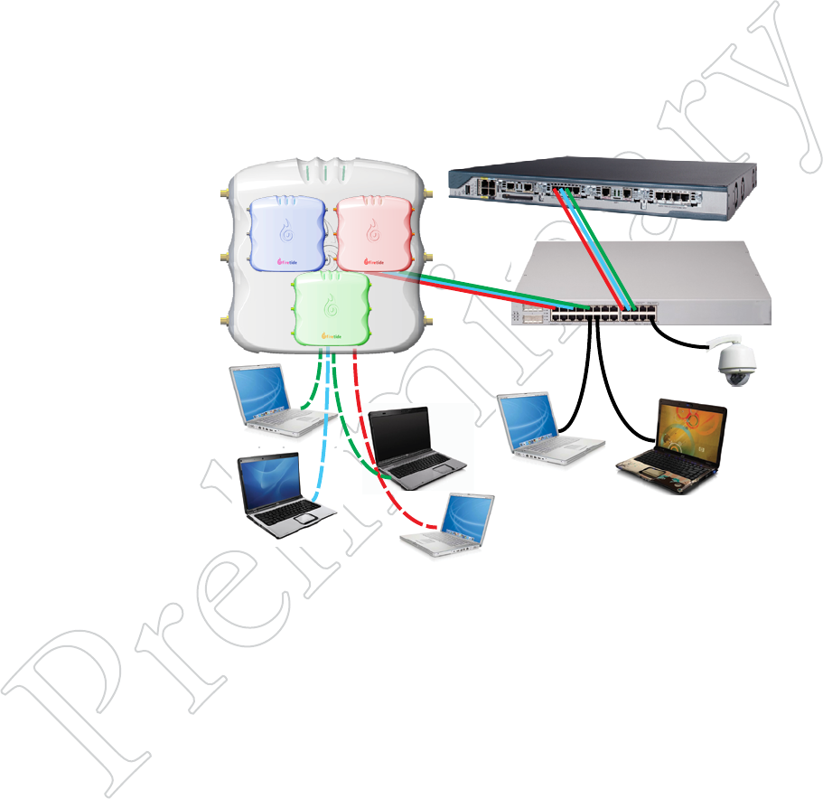
Figure 10.85 Three virTuAl
AcceSS poiNTS oN Three vlANS
This shows three virtual APs (or
profiles) implemented within one
physical AP. Each virtual AP has its
own VLAN. The router moves traffic
between them.
VLAN Terminology
Most common computer equipment is not VLAN-aware; that is, it is not
capable of generating VLAN-tagged traffic. This untagged traffic gets a tag
added to it by the Ethernet switch.
Access Points are one of the varieties of network equipment which can cre-
ate tagged traffic. One of the most common uses of VLANs is to isolate
802.11 wireless APs from each other, especially if the APs serve different
classes of users. This is particularly common when using virtual APs - sys-
tems where one physical 802.11 base station acts as several APs.
An example is shown in Figure 10.85. Three virtual APs have been created;
one for employees, one for guests, and a high-security one for finance. The
three virtual APs are represented as three tinted APs. Each virtual AP has its
own VLAN. This provides security and traffic isolation among the different
classes of users.
Employees
VLAN 20
Guests
VLAN 30
Finance
VLAN 40
VLAN-unaware
devices
HotPoint 5100 AP
Figure 10.85 also shows devices which are not VLAN-aware. These devices
must have a VLAN tag added to them by the switch, and the switch port
must be configured to do this.
Native VLANs, Trunk Ports, and Hybrid Trunk Ports
If untagged traffic arrives on a port that has not been configured to assign
a tag, the traffic is assigned to a default VLAN, usually referred to as the
Native VLAN.
Trunk Ports are used to move collections of VLAN traffic from device to
device. In Figure 10.85, trunk ports exist between the AP and the switch,
and between the switch and the router. These trunks move tagged traffic.
They do NOT move untagged traffic. Hybrid ports must be used to carry a
mix of tagged and untagged traffic.
VLANs 61
Implementing VLANs
VLAN implementation on a Firetide mesh should begin by determining the
following key parameters of the overall network VLAN implementation.
• Are end-point devices VLAN-aware?
• Will you need to carry trunked VLAN traffic across the mesh?
• Will you need wired ports on the mesh capable of handling both
VLAN trunks and untagged traffic? (These are called hybrid ports.)
• Is there a management VLAN, and if so what is the VLAN number?
• What VLAN number do you wish to assign as the Native VLAN? This
number will be used as the tag for untagged traffic.
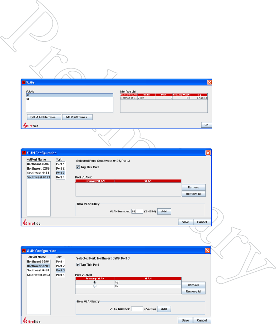
Assigning Port-Based VLANs
To cause a port to assign a VLAN tag to incoming traffic, select the VLAN
command from the mesh menu. A window will appear, as shown in Figure
10.86. Click on Edit VLAN Interface. A new window will open.
Figure 10.86 vlAN creATioN
wiNdow
This window is used to create and
modify both port-based VLANs and
VLAN trunks.
The new window is used to select a node, a port on that node, and a VLAN
number. Repeat this for every node and port in the mesh.
Figure 10.87 vlAN porT AS-
SigNMeNT wiNdow
In this example, port 3 of the South-
west node is about to be assigned
VLAN number 99.
You can add as many VLAN ports as
you wish, before clicking on Save.
In some cases, a port may need to accept tagged traffic while also assigning
a tag to untagged traffic. Additional, secondary VLANS can be added.
Figure 10.88 MulTiple vlAN
ASSigNMeNTS
If a port is connected to a VLAN-
aware device and also a non-VLAN-
aware devices, you can configure it to
add tags to untagged traffic. In this
example, tag 53 will be added to un-
tagged traffic, and the port will accept
tagged traffic with a value of 89.
64 HotView Pro Software Operation
VLAN Trunks
A VLAN trunk is simply a connection between two switches that carries
multiple VLANs. To create a trunk, select the VLANs command from the
Mesh menu, and click on Edit VLAN Trunks...
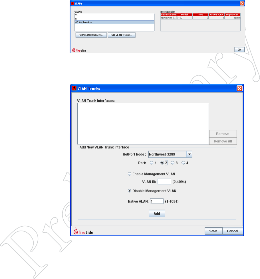
Figure 10.89 ediTiNg vlANS
ANd vlAN TruNkS
Use this window to view VLANs and
VLAN trunks.
A VLAN trunk port will only accept tagged traffic. Untagged traffic will be
blocked. (If you have untagged traffic as well as tagged traffic, you need to
use hybrid ports, covered in a later section.)
Figure 10.90 The vlAN
TruNk wiNdow
Specify the node and port on which
trunks will be accepted.
VLANs 61
Figure 10.91 coNFiguriNg A
vlAN TruNk
Here, a trunk port has been configured
on one node, and second trunk port is
about to be set up.
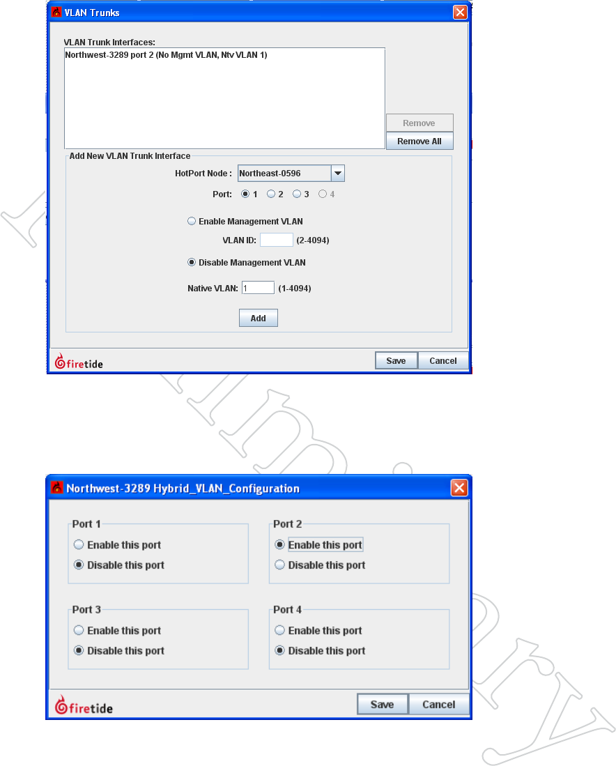
Hybrid Ports
If your network design requires that you handle both tagged and untagged
traffic on a port, you must configure that port as a Hybrid Port.
Figure 10.92 hybrid vlAN
coNFigurATioN
Here, port 2, which is already a trunk
port, is being enabled for hybrid
VLAN operation.

66 HotView Pro Software Operation

67
fCC ClASS A NoTiCe
Aclara devices comply with Part 15 of the FCC Rules. Operation is subject
to the following two conditions:
• This device may not cause harmful interference.
• This device must accept any interference received, including interfer-
ence that may cause undesired operation.
fCC pART 15 NoTe
This equipment has been tested and found to comply with the limits for a
Class A digital device, pursuant to Part 15 of the FCC Rules. These limits
are designed to provide reasonable protection against harmful interference
in an office installation. This equipment generates, uses and can radiate
radio frequency energy and, if not installed and used in accordance with
the instructions, may cause harmful interference to radio communications.
However, there is no guarantee that interference will not occur in a particu-
lar installation. If this equipment does cause harmful interference to radio
or television reception, which can be determined by turning the equipment
off and on, the user is encouraged to try to correct the interference by one
or more of the measures shown at right:
fCC pART 90 NoTe
This equipment has been tested pursuant to FCC Part 90, DSRC-C mask
certification, and is approved for use in the US on Public Safety bands by
licensed Public Safety agencies.
pUbliC SAfeTy bANd
Pursuant to Part 90.1215, use of antennas with gain greater than 9 dBi and
up to 19 dBi in the 4.940 - 4.990 GHz Public Safety band is permissible
without reduction of TX output power. The antenna shall have a directional
gain pattern in order to meet the requirement of point to point and point
to multi-point operation.
modifiCATioNS
Any modifications made to this device that are not approved by Aclara,
Inc. may void the authority granted to the user by the FCC to operate this
equipment.
fCC RAdiATioN expoSURe STATemeNT
To ensure compliance with the FCC’s RF exposure limits, the antenna used
for this transmitter must be installed to provide a separation distance from
all persons.
The 5900 must not be co-located or operated in conjunction with any other
antenna or transmitter. Installers and end users must follow these installa-
tion instructions.
Appendix A Regulatory Information
iNTeRfeReNCe CoRReCTioN
•Reorient or relocate the receiving
antenna.
•Increase the separation between the
equipment and receiver.
•Connect the equipment into an
outlet on a circuit dierent from
that to which the receiver is con-
nected.
•Consult the dealer or an experi-
enced radio/television technician
for help.
miNimUm diSTANCeS
•For the 5900, the distance must be
76 cm.
68 HotView Pro Software Operation
iNSTAllATioN
Antenna(s) for this unit must be installed by a qualified professional. Op-
eration of the unit with non-approved antennas is a violation of U.S. FCC
Rules, Part 15.203(c), Code of Federal Regulations, Title 47.
Canadian Compliance Statement
This Class A Digital apparatus meets all the requirements of the Canadian
Interference-Causing Equipment Regulations.
Cet appareil numerique de la classe A respecte les exigences du Reglement
sur le material broilleur du Canada.
This device complies with Class A Limits of Industry Canada. Operation is
subject to the following two conditions:
1. This device may not cause harmful interference, and
2. This device must accept any interference received, including interference
that may cause undesired operation.
Aclara 5900 Series wireless mesh nodes are certified to the requirements of
RSS-210 for 2.4 and 5 GHz spread spectrum devices. The use of this device
in a system operating either partially or completely outdoors may require
the user to obtain a license for the system according to the Canadian regula-
tions. For further information, contact your local Industry Canada office.
Canadian units will not transmit in the 5600-5650 MHz band.
DFS Notice
Aclara 5900 Series products sold in the US are preset for US frequency
bands, channels, and power levels. No country code setting is required,
or permitted. This chapter explains how to enable DFS operation when
operating in the US, and how to correctly configure DFS channels so as to
maintain compliance with FCC regulations and guidelines.
DFS operation can only be enabled and configured by a DFS-qualified
professional installer. Contact Aclara for details.
All channels listed in the table must comply with basic DFS rules, includ-
ing channel avoidance when radar signals are detected. Channels 120, 124,
and 128 have been removed from DFS service completely. These channels
must not be used in the US anywhere, at any time. They do not appear in
channel listing in any Aclara product, and are only listed here for historical
reference. Channels 116 and 132 may only be used when certain special
rules have been followed. The channels can only be used if either of the fol-
lowing two conditions are met:
• The transmitting antenna is more than 35 km from all TDWR stations;
OR
• The TDWR is operating on a frequency more than 30 MHz different
than the equipment.
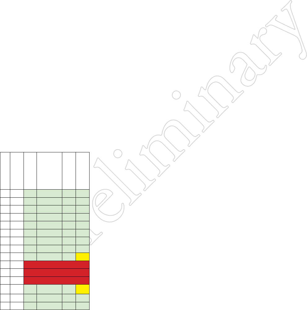
Channel
Center
Frequency
Distance
Determination
Registration
Channel
Avoidance
TDWR
Restrictions
52 5260 Yes If > 35 km Yes No
56 5280 Yes If > 35 km Yes No
60 5300 Yes If > 35 km Yes No
64 5320 Yes If > 35 km Yes No
100 5500 Yes If > 35 km Yes No
104 5520 Yes If > 35 km Yes No
108 5540 Yes If > 35 km Yes No
112 5560 Yes If > 35 km Yes No
116 5580 Yes If > 35 km Yes Yes
120 5600 Banned
124 5620 Banned
128 5640 Banned
132 5660 Yes If > 35 km Yes Yes
136 5680 Yes If > 35 km Yes No
140 5700 Yes If > 35 km Yes No
TAble 11.1 dFS chANNelS
This table shows channels defined as
DFS. They are color-coded based on
the applicable rule set.

69
diSTANCe
You must determine if there are any transmitting elements (i.e., any Aclara
product) within 35 km of any TDWR system. Refer to Table 11.2 for a
list of TDWR installations in the US. If there are, you should register the
installation.
RegiSTRATioN
A voluntary WISPA-sponsored database has been developed that allows
registration of devices within 35 km of any TDWR location (see http://
www.spectrumbridge.com/udia/home.aspx). This database is used by gov-
ernment agencies to expedite resolution of any interference with TDWRs.
ChANNel AvoidANCe
When a radar signature is detected on a channel, transmitters must stop
using that channel. The Channel Selection control lets you configure the
channels to which the system can switch, and the channels which must be
avoided (blacklisted).
TDWR-Restricted Additional Requirements
Terminal Doppler Weather Radar systems operate in the 5600 MHz band,
and must be kept free of interference from all other types of equipment. For
this reason, the FCC has removed channels 120, 124, and 128 (5600-5640)
from service, and placed additional restrictions on channels 116 (5580
MHz) and 132 (5660 MHz).
If you are within 35 km of a TDWR, you may not operate on any channel
that is within 30 MHz of the listed TDWR frequency. In some instances it
is possible that a device may be within 35 km of multiple TDWRs. In this
case the device must ensure that it avoids operation within 30 MHz for each
of the TDWRs.
This requirement applies even if the master is outside the 35 km radius but
communicates with outdoor clients which may be within the 35 km radius
of the TDWRs.
The requirement for ensuring 30 MHz frequency separation is based on the
best information available to date. If interference is not eliminated, a dis-
tance limitation based on line-of-sight from TDWR will need to be used. In
addition, devices with bandwidths greater than 20 MHz may require greater
frequency separation.

70 HotView Pro Software Operation
ST City Longitude Latitude Frequency Elev Ht
AZ Phoenix W 112 09 46 N 33 25 14 5610 MHz 1024 64
CO Denver W 104 31 35 N 39 43 39 5615 MHz 5643 64
FL Ft Lauderdale W 080 20 39 N 26 08 36 5645 MHz 7 113
FL Miami W 080 29 28 N 25 45 27 5605 MHz 10 113
FL Orlando W 081 19 33 N 28 20 37 5640 MHz 72 97
FL Tampa W 082 31 04 N 27 51 35 5620 MHz 14 80
FL West Palm Beach W 080 16 23 N 26 41 17 5615 MHz 20 113
GA Atlanta W 084 15 44 N 33 38 48 5615 MHz 962 113
IL Mccook W 087 51 31 N 41 47 50 5615 MHz 646 97
IL Crestwood W 087 43 47 N 41 39 05 5645 MHz 663 113
IN Indianapolis W 086 26 08 N 39 38 14 5605 MHz 751 97
KS Wichita W 097 26 13 N 37 30 26 5603 MHz 1270 80
KY Covington-Cincinnati W 084 34 48 N 38 53 53 5610 MHz 942 97
KY Louisville W 085 36 38 N 38 02 45 5646 MHz 617 113
LA New Orleans W 090 24 11 N 30 01 18 5645 MHz 2 97
MA Boston W 070 56 01 N 42 09 30 5610 MHz 151 113
MD Brandywine W 076 50 42 N 38 41 43 5635 MHz 233 113
MD Beneld W 076 37 48 N 39 05 23 5645 MHz 184 113
MD Clinton W 076 57 43 N 38 45 32 5615 MHz 249 97
MI Detroit W 083 30 54 N 42 06 40 5615 MHz 656 113
MN Minneapolis W 092 55 58 N 44 52 17 5610 MHz 1040 80
MO Kansas City W 094 44 31 N 39 29 55 5605 MHz 1040 64
MO Saint Louis W 090 29 21 N 38 48 20 5610 MHz 551 97
MS Desoto County W 089 59 33 N 34 53 45 5610 MHz 371 113
NC Charlotte W 080 53 06 N 35 20 14 5608 MHz 757 113
NC Raleigh Durham W 078 41 50 N 36 00 07 5647 MHz 400 113
NJ Woodbridge W 074 16 13 N 40 35 37 5620 MHz 19 113
NJ Pennsauken W 075 04 12 N 39 56 57 5610 MHz 39 113
NV Las Vegas W 115 00 26 N 36 08 37 5645 MHz 1995 64
NY Floyd Bennett Field W 073 52 49 N 40 35 20 5647 MHz 8 97
OH Dayton W 084 07 23 N 40 01 19 5640 MHz 922 97
OH Cleveland W 082 00 28 N 41 17 23 5645 MHz 817 113
OH Columbus W 082 42 55 N 40 00 20 5605 MHz 1037 113
OK Aero. Ctr TDWR #1 W 097 37 31 N 35 24 19 5610 MHz 1285 80
OK Aero. Ctr TDWR #2 W 097 37 43 N 35 23 34 5620 MHz 1293 97
OK Tulsa W 095 49 34 N 36 04 14 5605 MHz 712 113
OK Oklahoma City W 097 30 36 N 35 16 34 5603 MHz 1195 64
PA Hanover W 080 29 10 N 40 30 05 5615 MHz 1266 113
PR San Juan W 066 10 46 N 18 28 26 5610 MHz 59 113
TN Nashville W 086 39 42 N 35 58 47 5605 MHz 722 97
TX Houston Intercontl W 095 34 01 N 30 03 54 5605 MHz 154 97
TX Pearland W 095 14 30 N 29 30 59 5645 MHz 36 80
TX Dallas Love Field W 096 58 06 N 32 55 33 5608 MHz 541 80
TX Lewisville DFW W 096 55 05 N 33 03 53 5640 MHz 554 31
UT Salt Lake City W 111 55 47 N 40 58 02 5610 MHz 4219 80
VA Leesburg W 077 31 46 N 39 05 02 5605 MHz 361 113
WI Milwaukee W 088 02 47 N 42 49 10 5603 MHz 820 113
Latitude and Longitude based on NAD83 datum.
TAble 11.2 Tdwr iNSTAllA-
TioNS
This list is current as of August 2011.
Elevation and antenna height shown in
feet. Refer to www.fcc.gov for the most
current version.

Revision History
Revision Date Notes
1.0draft3 2012-02-14 Initial Release