Firetide 7100-1 Hotport Model 7100 Mesh Node User Manual Revised Manual
Firetide Inc. Hotport Model 7100 Mesh Node Revised Manual
Firetide >
Contents
- 1. Revised Manual
- 2. Manual
Revised Manual
HotPort
Manual Revision 1.01-DRAFT 2010-01-07
The contents of this Installation Guide are subject to change without notice.
Please refer to the Firetide partners web site, partners.retide.com, for current versions.
Hardware Installation Guide
HotPort Series 7000
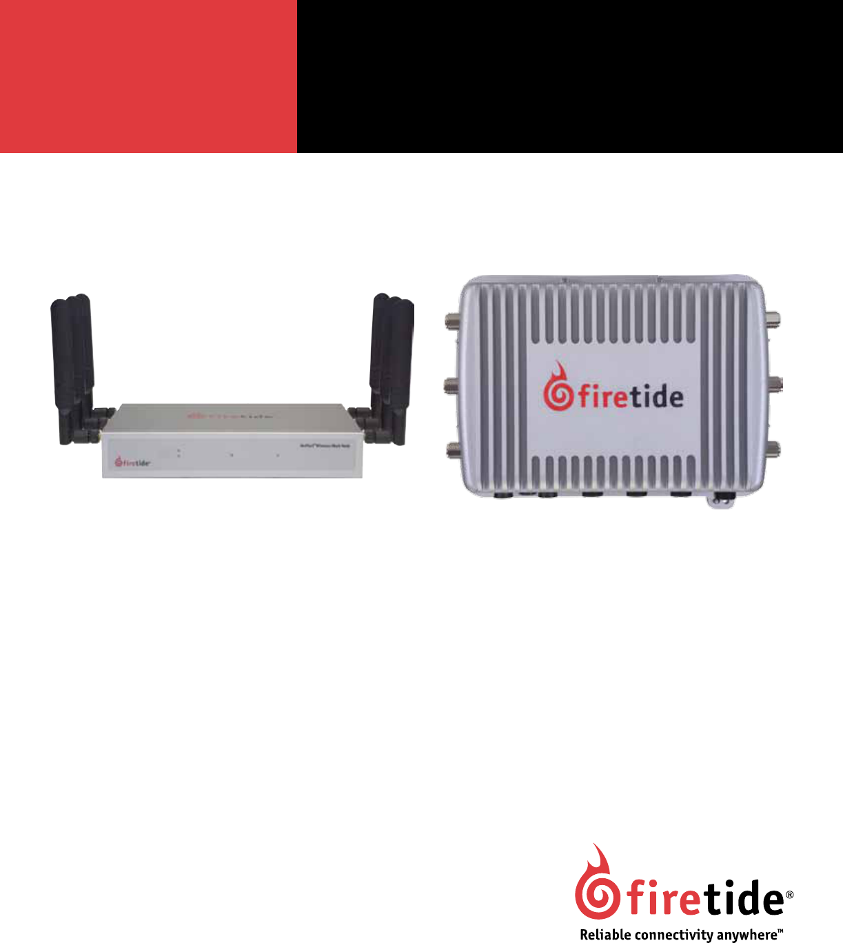
Indoor and Outdoor Wireless Mesh Nodes
HotPort 7200 - Outdoor NodeHotPort 7100 - Indoor Node
mesh radio 1
mesh radio 2 status power
2 HotPort Series 7000 Mesh Nodes January 2010
Firetide Limited End User Product Warranty
Pursuant to all provisions described herein, Firetide hardware products
and Firetide antennas are warranted for one (1) year from the date of
purchase against defects in the build materials and workmanship. Firetide
does not warrant that the Products will meet any requirements or speci-
cations of any End User Customer. This warranty applies to the entire
Firetide product, including the AC power adapter.
Pursuant to all provisions described herein, Firetide software products
are warranted for ninety (90) days from the date of purchase against de-
fects in the build materials and workmanship. Firetide also warrants that
the Software will materially conform to the documentation supplied by
Firetide with the Software. In the event that the Software fails to materi-
ally conform to the documentation and an authorized Firetide reseller is
notied in writing of such failure within the warranty period, Firetide or
its reseller shall use commercially reasonable efforts to promptly correct
the nonconformity. Firetide does not warrant that the use of the Software
will be uninterrupted or error free.
The above warranties are void if the alleged defect cannot be veried by
Firetide or if, as determined by Firetide, the product failure was due to
tampering, abuse, misuse, accident, shipping, handling, or storage; or
if the product has been installed, used, or maintained in a manner not
described in the product user manual; or if the product has been altered
in any way; or if product serialization has been altered. Any attempt to
disassemble or repair the product by anyone other than Firetide immedi-
ately voids this warranty.
This warranty applies only to the original End User purchaser of the prod-
uct and may not be transferred to any other individual or entity.
THE FOREGOING ARE THE EXCLUSIVE WARRANTIES APPLICABLE TO THE
PRODUCT INCLUDING THE SOFTWARE, AND THE EXCLUSIVE REMEDY FOR
DEFECTS IN THE PRODUCT. FIRETIDE DISCLAIMS ALL OTHER WARRANTIES,
WHETHER EXPRESS, IMPLIED, STATUTORY OR OTHERWISE, INCLUDING BUT
NOT LIMITED TO IMPLIED WARRANTIES OF MERCHANTABILITY, NON-IN-
FRINGEMENT OR FITNESS FOR A PARTICULAR PURPOSE. SOME LAWS DO NOT
ALLOW THE EXCLUSION OF IMPLIED WARRANTIES SO TO THAT EXTENT THIS
LIMITATION MAY NOT APPLY TO YOU.
In no event will Firetide be liable for any special, incidental, consequen-
tial, punitive or indirect damages whatsoever (including, without limita-
tion, damages for loss of prots, business interruption, loss of informa-
tion, or other pecuniary loss) arising out of the use or inability to use
the product or the performance, interruption or failure of the product,
irrespective of the cause of action, even if Firetide has been advised
of the possibility of such damages. Firetide’s cumulative liability for all
claims arising out of or in connection with this warranty will not ex-
ceed the amount paid by the original End User purchaser to purchase the
product. The amounts payable for the product are based in part on these
limitations and these limitations shall apply notwithstanding the failure
of essential purpose of any remedy. Some jurisdictions do not allow the
exclusion or limitation of incidental or consequential damages, so to that
extent the above limitations or exclusions may not apply to you.
By using the product the original End User purchaser agrees to and is
bound by these terms and conditions.
In the event that a product fails to meet this warranty and Firetide’s
authorized reseller is notied in writing of such failure within the war-
ranty period, Firetide shall, at its own discretion, either repair the prod-
uct or replace it with the same or a functionally-equivalent product free
of charge. Replacement products may contain refurbished materials in
whole or in part. Firetide will honor this warranty provided the product is
returned through an authorized Firetide reseller or dealer with shipping
charges prepaid, along with a proof of purchase describing the original
purchase date and product serial numbers if applicable. The authorized
reseller must acquire a Return Materials Authorization (RMA) number from
Firetide prior to returning any product. Firetide does not accept ship-
ments of defective products without shipping charges prepaid.
This symbol is intended to alert the user to the pres-
ence of important operating, maintaining and servic-
ing instructions in the literature accompanying the
HotPort node. Failing to comply with this instruction
may result in electrical shock.
This symbol is intended to alert the user to the pres-
ence of important operating, maintaining and servic-
ing instructions in the literature accompanying the
HotPort node. Failing to comply with this instruction
may result in a hazard.
Copyright Notice: ©2003-2010 Firetide, Inc. All rights reserved.
Trademarks: Firetide, the Firetide logo, Instant Mesh Networks, HotPort, and HotPoint are trademarks of Firetide, Inc. All other trademarks are the
property of their respective owners.
Safety Instructions
The HotPort outdoor wireless mesh node must be installed by a quali-
ed professional such as a licensed electrician. Failure to install this
equipment properly may result in equipment damage and personal
injury or death.
This symbol is intended to alert the user to the pres-
ence of non-insulated dangerous voltage that may be
of sufcient magnitude to constitute a risk of lethal
electric shock to persons.

Firetide Instant Mesh Networks 3 January 2010
Contents
HotPort Node Installation ........................................................................ 5
Package Contents.............................................................................5
Planning Your Installation ......................................................................6
Indoor Node Installation ........................................................................ 6
Positioning Indoor Antennas ................................................................... 6
Outdoor Node Installation ....................................................................... 7
Preparing the Unit............................................................................7
Preparing Earth Ground.........................................................................7
Safety Considerations..........................................................................7
Antenna Placement ...........................................................................8
Mounting Outdoor Antennas .................................................................... 8
Mounting Guidelines ......................................................................... 8
Mounting Bracket.............................................................................8
Mounting the Universal Bracket ...................................................................9
Using Mounting Straps ........................................................................ 9
Connecting Cables ...........................................................................10
Power Connection ...........................................................................10
Appendix A - Contacting Firetide ...................................................................11
Appendix B - Connector Wiring ....................................................................12
HotPort Outdoor Node AC Power Connector ..........................................................12
HotPort Outdoor Node DC Power Connector ..........................................................12
Custom Power Cables .........................................................................12
Appendix C - Specications .......................................................................13
Common Specications........................................................................13
Wireless Interface ...........................................................................13
Series 7200 Outdoor Unit Specications ............................................................14
Series 7100 Indoor Unit Specications .............................................................14
Appendix D - Regulatory Notices ...................................................................15
USA ....................................................................................15
Canadian Compliance Statement .................................................................15

4 HotPort Series 7000 Mesh Nodes January 2010
• Dangerous voltages inside.
• No serviceable parts inside.
• Refer to qualied service personnel.
• Unit must be disconnected from power prior to servicing.
• Unit has tamper-evident labeling that indicates when the cover has been removed.
Do not open the cover
Caution! Risk of electric shock!
POWER LINES CAN BE LETHAL
Do not install the HotPort outdoor mesh node where possible con-
tact with power lines can be made. Antennas, poles, towers, guy
wires, or cables may lean or fall and contact these lines. People
may be injured or killed if they are touching or holding any part
of the equipment when it contacts electric lines. Make sure there
is NO possibility that equipment or personnel can come in contact
directly or indirectly with power lines.
ASSUME ALL OVERHEAD LINES ARE POWER LINES
The horizontal distance from a tower, pole or antenna to the near-
est power line should be at least twice the total length of the
pole/antenna combination. This will ensure that the pole will not
contact power if it falls either during or after installation.
SURVEYING THE SITE
Look over the entire site before beginning any installation and an-
ticipate possible hazards. Never assume anything without check-
ing it out for yourself! Don’t take shortcuts!
TO AVOID FALLING, USE SAFE PROCEDURES WHEN WORKING AT
HEIGHTS ABOVE GROUND
• Select equipment locations that will allow safe and simple in-
stallation.
• Don’t work alone. A friend or co-worker can save your life if an
accident happens.
• Don’t attempt repair work when you are tired. Not only will
you be more careless, but your primary diagnostic tool -
deductive reasoning - will not be operating at full capacity.
• Use approved non-conducting ladders, shoes, and other safety
equipment. Make sure all equipment is in good repair.
• If a tower or pole begins falling, don’t attempt to catch it.
Stand back and let it fall.
• If anything such as a wire or pole does come in contact with a
power line, DON’T TOUCH IT OR ATTEMPT TO MOVE IT. Instead,
save your life by calling the power company.
• Don’t attempt to erect antennas or towers on windy days.
• MAKE SURE ALL TOWERS AND POLES ARE SECURELY GROUND-
ED, AND ELECTRICAL CABLES CONNECTED TO ANTENNAS HAVE
LIGHTNING ARRESTORS. This will help prevent re damage or
human injury in case of lightning, static build-up, or short cir-
cuit within equipment connected to the antenna. The HotPort
outdoor node has built-in lightning protection. Be sure that
any other equipment connected to the HotPort node also has
the same level of protection.
• The base of the antenna pole or tower must be connected di-
rectly to the building protective ground or to one or more
approved grounding rods, using 10 AWG ground wire and cor-
rosion-resistant connectors.
• Refer to the National Electrical Code for grounding details.
IF AN ACCIDENT SHOULD OCCUR WITH THE POWER LINES:
• DON’T TOUCH THAT PERSON, OR YOU MAY BE ELECTROCUTED.
• Use a non-conductive dry board, stick, or rope to push or drag
them so they no longer are in contact with electrical power.
• Once they are no longer contacting electrical power, administer
CPR if you are certied.
• Immediately have someone call for medical help.
Firetide Instant Mesh Networks 5 January 2010
HotPort Node Installation
This hardware installation guide describes how to install the HotPort node safely. The HotPort is intended to be installed by trained
professionals. Be sure to read and understand all installation and safety instructions before proceeding with the installation.
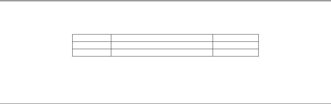
Table 1. Summary of HotPort Series 7000 Mesh Nodes
Model Use No. of Radios
7100 Indoor, Worldwide, 2.4, 4.9, 5 GHz 1 or 2
7200 Outdoor, Worldwide, 2.4, 4.9, 5 GHz 1 or 2
This guide covers both dual-radio and single radio models. The only difference between dual-radio models and single-radio models is
the second radio. Single radio models will identify themselves in software as 7101 or 7201; dual radio models will identify themselves
as 7102 or 7202.
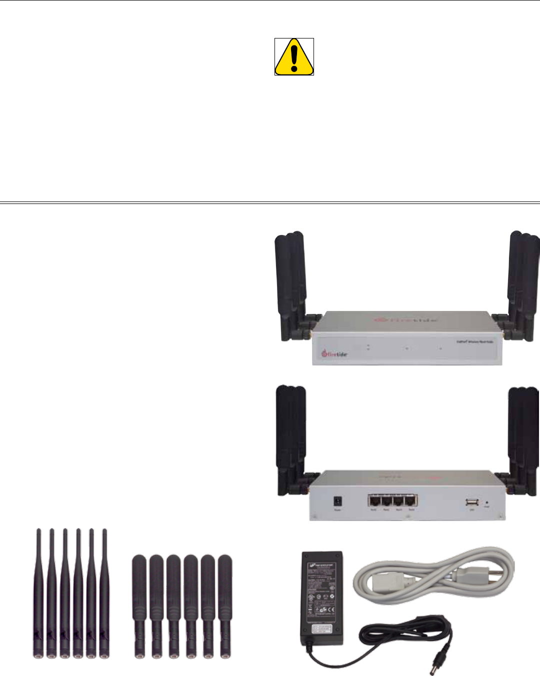
Package Contents
The HotPort node package contains the following items. If you are missing any of these items, contact your Firetide reseller.
HotPort 7100 Indoor Mesh Node
• HotPort node in plenum-rated enclosure.
Antennas
• Six detachable 2.4 GHz 5 dBi omnidirectional antennas.
• Six detachable 5 GHz 5 dBi omnidirectional antennas.
• These are the only antennas approved for use with the 7100 in
the 2.4, 4.9, and 5 GHz bands..
Power
• External power module with NEMA5-15 (US) to IEC-320 cord.
Other IEC cords are available separately.
Documentation
• HotPort 7100 Quick Install Guide.
• Warranty and registration card.
Compact Disk (CD)
• HotView Pro software.
• HotView Pro Reference Guide.
• HotPort 7000 Hardware Installation Guide
• Warranty/Registration Card.
• EULA.
HotPort 7200 Outdoor Mesh Node
• HotPort node in NEMA-4X enclosure with weatherproof caps.
• Six N to reverse-polarity SMA adapters.
• Mounting bracket for pole and wall mounting. Designed to t
37 mm to 50 mm (1.5 in to 2.0 in) poles.
Mounting Kit
• U-Bolts, M6x1.0-80mm, with at washers, split washers, nuts.
• Claw-tooth pole grippers.
• M6x1.0-40mm hex bolt.
• M6x1.0-20mm hex bolt.
• Hex-head socket wrench.
Antennas
• Six detachable 2.4 GHz indoor omnidirectional antennas.
• Six detachable 5 GHz indoor omnidirectional antennas.
Power
• AC power cord with NEMA 5-15 (US) plug. Other IEC cords are
available separately.
Documentation
• HotPort 7200 Quick Install Guide.
• Warranty and registration card.
Compact Disk (CD)
• HotView Pro software.
• HotView Pro Reference Guide.
• HotPort Series 7000 Hardware Installation Guide.
• Warranty/Registration Card.
• EULA.
6 HotPort Series 7000 Mesh Nodes January 2010
Staging Considerations
You should set up and test your nodes indoors, on a bench or
table, before installing them. This will allow you to pre-congure
the nodes so that they are all on the same RF channel, etc. You
will use HotView Pro to congure the HotPort nodes and create a
small mesh network. Test the network settings you plan to use.
1. Check to see that all nodes are visible in HotView Pro. If not,
troubleshoot per directions in the HotView Reference Guide.
2. Set the Country Code for your country of operation.
3. Re-verify that all nodes are visible, and verify that dual-radio
nodes have both radios correctly meshed.
Planning Your Installation
Warning: The staging antennas provided with Firetide outdoor
nodes are for temporary use only. They MUST be re-
placed with outdoor-rated antennas as soon as the
mesh is staged and operational. The staging antennas
are NOT waterproof and NOT moisture resistant. If used
outdoors, the antennas may fail.
Your CD has a copy of Firetide’s Accessory Guide. Contact your
Firetide Reseller for assistance in selecting and ordering outdoor
antennas suitable for your application(s).
Indoor Node Installation
Indoor node installation is straightforward. Firetide recommends
that you power up and congure all nodes on a table or bench
before deployment. Use HotView or HotView Pro to congure your
mesh. Place the unit on a table or shelf. Apply power. The power
LED should illuminate immediately; after about 60 to 90 seconds,
the status LED should switch to steady green.
Note the location of the reset button in the lower right corner of
the rear panel. To reset the unit, apply power and wait until the
unit has fully booted and the status light has come on. Then use
a paperclip to press and hold the reset button until the status LED
blinks.
Positioning Indoor Antennas
The Firetide-supplied antennas are rated for use in dry, indoor
environments. If the antenna is exposed to weather, moisture, or
high humidity, it may fail. Use an approved outdoor-rated antenna
instead.
MIMO technology takes advantage of signal reections to improve
performance. Antenna orientation affects this. Firetide recom-
mends that you begin deployment with the antennas on each ra-
dio parallel and in the same plane as the node itself.
Depending on performance, you may wish to try other orienta-
tions.
Figure 1. Staging Antennas
Figure 2. HotPort Series 7100 Mesh Node - Front View
mesh radio 1
mesh radio 2 status power
Figure 3. HotPort Series 7100 Mesh Node - Rear View
Figure 4. Power Supply

Firetide Instant Mesh Networks 7 January 2010
The HotPort node must be properly connected to earth ground.
Failure to do so may result in equipment damage, injury, or death.
The product warranty does not cover damages resulting in part or
in whole from improper grounding. Consult your location’s build-
ing and electrical codes regarding antennas and follow them, or
consult the National Electric Code (NEC).
• If connecting to a tower or pole, connect the base of the tower
pole directly to the building’s ground or to one or more ap-
proved grounding rods using 10 AWG ground wire and corro-
sion-resistant connectors.
• Connect the grounding cable to rain gutters only if the
rain gutter is connected to earth ground.
Outdoor Node Installation
Preparing the Unit
1. Pre-assemble the antenna, HotPort node, and other devices to
a metal pole and antenna and then relocate and attach it to a
roof top. It is often easier to install all devices to one object,
such as a pole, and then attach the pole to the roof. In many
cases, connecting the devices to a pole already attached to
the roof top can be difcult and dangerous.
2. A lightning surge suppressor must be used. Some antennas
include one. If not, you must install a lightning suppressor.
3. Install the antenna and any wireless devices higher than the
HotPort node. Take care when locating the HotPort node far
away from the antenna; a short antenna cable gives better
performance than a longer one. Firetide recommends that you
use antenna cables less than 3 meters.
4. The HotPort node and its antenna must both be grounded.
5. Use weatherproong kits that include non-vulcanized rubber
to weatherproof connectors and antennas. All Ethernet cables
must be waterproofed; standard RJ-45 connectors do not last
outdoors.
6. Power over Ethernet: Consider which devices require PoE and
what the required input voltage will be.
7. Connect peripheral devices to the HotPort node.
8. Connect power to the HotPort node and peripherals.
WARNING
The staging antennas provided with Firetide outdoor
nodes and access points are for temporary use only.
They MUST be replaced with outdoor-rated antennas
as soon as the mesh is staged and operational.
The staging antennas are NOT waterproof or moisture resistant. If
used outdoors or in humid environments, the antennas may fail.
Your CD has a copy of Firetide’s Accessory Guide. Contact your
Firetide Reseller for assistance in selecting and ordering outdoor
antennas suitable for your application(s).
Tools Needed
For HotPort 7200 outdoor nodes, you will need:
• #2 Phillips screwdriver.
• Small adjustable wrench.
• Wire cutters to cut tie wraps around cables.
• Weatherproong kit – this kit provides electrical tape and butyl
mastic.
Depending on the installation location, you may need ladders, a
lift truck, or other means to access the actual installation loca-
tions.
Preparing Earth Ground
• Ground rods should be copper-plated, 1.8 - 2.4 m (6 - 8 ft)
long.
• Install all grounding components in straight lines. If bends are
unavoidable, do not make sharp turns.
• Earth-to-ground should not be more than 10 ohms.
• Understanding the soil is very important in order to create a
proper earth ground. If your soil is rocky or sandy, drive your
ground rods and then pull them back out and dump an ap-
proved ground enhancement material into the holes where the
grounding rods go. Then replace the grounding rods. Keep in
mind that some salt compounds are corrosive and can cause
copper to corrode.
Safety Considerations
Consider the following safety issues.
• Use approved, non-conducting ladders.
• Use approved and non-conducting shoes and other safety
equipment. Make sure that all equipment is in good repair.
• If mounting to a pole or tower, make sure all poles and towers
are securely grounded.
• Make sure antennas are DC grounded; if not, cables must have
lightning arrestors.
8 HotPort Series 7000 Mesh Nodes January 2010
• The HotPort node and its antenna must both be grounded.
• Large or heavy antennas must be mounted to a pole or other
secure structure.
• The antennas should not be within 1 meter (~3 ft.) of any metal
bar or structure, and ideally not within 1 meter (~3 ft.) of any
concrete or stone structure. In general, try to locate the anten-
nas as far from such objects as practicable.
• Shorter antenna cables give better performance. Plan your in-
stallation to minimize antenna cable length. However, do not
attempt to splice or shorten the antenna cable.
• If a longer coax cable is required, the system requires a high-
quality, low-loss 50 ohm cable. Contact your local distributor
to obtain a 50 ohm cable with the correct connectors. Firetide
recommends LMR400 cable or better.
• Minimize use of connectors and adapters.
• Once you’ve veried that everything is working, waterproof all
connections!
• Do not mount the antenna pole near power lines.
• When mounting next to an access point, mount the access
point lower on the pole and at least 1 meter (~3 ft.) from the
antennas. You can also mount the access point on a horizontal
bar to achieve the required separation.
Antenna Placement
Firetide recommends the use of antennas specically designed for
MIMO applications. While it is possible to select and mount six
individual antennas, determining correct placement and spacing
is difcult. Use an antenna engineered for best results with MIMO.
If you are not using three antennas on each radio, install anten-
nas in order, from the front of the unit toward the back. Do not
‘skip’ antenna connections.
Mounting Outdoor Antennas
Once you determine which RF band to use, you can order spectrum-
specic high-gain antennas from Firetide or another supplier.
Many installers prefer to mount the HotPort node and its associ-
ated antennas to a short bar, typically about 2 meters long. This
entire bar assembly is them mounted horizontally to the vertical
mast of the main antenna structure.
Mounting Guidelines
• It is often easier to install all devices onto a pole, and then
attach the pole to the roof. In many cases, connecting the de-
vices to a pole already attached to the roof top can be difcult
and dangerous.
• A lightning surge suppressor must be used. Some antennas
include one. If not, install a lightning surge suppressor.
• Locate the HotPort close to the antenna; a short antenna cable
gives better performance than a longer one. Firetide recom-
mends antenna cables less than 3 meters.
Mounting Bracket
Your HotPort node shipped with a two-piece mounting bracket.
This bracket is of the same design as the HotPort 6202 outdoor
bracket, so you can install a 7200 in place of a 6201 or 6202.
The assembly is shown below. To mount the node, remove the
outer piece, by loosening the thumb screws.
The inner bracket can be left attached to the node, as shown
below.
Firetide Instant Mesh Networks 9 January 2010
Mounting the Universal Bracket
You can mount the node to a wall, a light pole, or an irregularly
shaped pole. The universal mounting bracket has been designed
with multiple holes and slots to allow mounting with bolts, straps,
or other methods. Extra nuts and bolts are provided for this pur-
pose; don’t be alarmed if you have leftover fasteners when instal-
lation is complete.
Wall Mounting
The Universal Mounting Bracket contains holes and slots to allow
it to be mounted via U-bolts or straps. Use four screws (not sup-
plied) to attach the universal mounting bracket securely to the
wall using the four holes near the top and bottom of the universal
mounting bracket. Use appropriate anchors when attaching to ma-
sonry or other materials.
Pole Mounting
1. Insert the two U-bolts through the holes in the claw-toothed
pole-gripper piece.
2. On each U-bolt, place a washer, a lock washer, and a nut.
Smaller pole diameters usually require a second nut as a spac-
er to hold the bracket away from the U-bolt clamp. Finger-
tighten the nuts. There should be about 12-15 mm (1/2-5/8”)
of U-bolt sticking past the second nut.
Mount the second U-bolt. Use the mounting bracket as a guide to
correctly space the two U-bolts, then tighten the nuts. A horizon-
tal pole-mount is also shown for reference.
Use lock washers and nuts to secure the bracket to the U-bolts.
Installation on a horizontal pole is the same, you just use differ-
ent holes in the mounting plate.
This shows the use of spacer nuts when mounting to smaller poles.
You may nd an open-end wrench useful for tightening the inner
nuts in these applications.
Using Mounting Straps
For poles with diameters larger than 50 mm (2”), irregularly
shaped poles, or light poles, you can use mounting straps (not
supplied) to mount the HotPort enclosure.
1. Position the universal mounting bracket against the pole.
2. Thread two mounting straps around the pole and through the
slots located near the top and bottom of the universal mount-
ing bracket. Secure the mounting straps.
3. Attach the enclosure to the universal mounting bracket by
sliding the metal clips on the back of the enclosure into the
metal straps on the universal mounting bracket.
Secure the enclosure to the universal mounting bracket using the
four captive screws on the sides of the universal mounting bracket.
Mounting Antennas
Now that you’ve attached the Universal Mounting Plate, you are
ready to proceed to the next steps. Most outdoor applications use
separately-mounted antennas, if so, mount your antennas now. If
you are using the temporary staging antennas, the next step is to
attach the HotPort node itself.
U-bolt Mounted
on Pole
U-bolts, Vertical and
Horizontal Mounting
Universal Mounting Bracket
Attached to Pole
Mounting Bracket
Showing Use of
Spacer Nuts
10 HotPort Series 7000 Mesh Nodes January 2010
Connecting Cables
After your node is mounted, attach the six antennas, the power cable, and any Ethernet cables you need. Note that all of the weath-
erproof caps have been removed from the node for illustrative purposes. You should not leave any unused connector uncovered.
Figure 5. HotPort 7200 Bottom Panel
port 1port 2port 3dc power usbac power
power status radio 1 radio 2 ethernet
–mesh–
Note the locations of the reset button under the weatherproof cap. To reset the unit, apply power and wait until the unit has fully
booted and the status light has come on. Then use a paperclip to press and hold the reset button until the status LED blinks.
Power Connection
Connect the suppled AC power cable to AC power and to the HotPort node. If you wish to power your node with DC power, you will
need a source of power which can deliver 12 V ±10% at 3 A. Information on building custom power cables is shown in Appendix B. Do
not connect both AC and DC supplies simultaneously.
Powering Other Ethernet Devices
Ports 2 and 3 on a Series 7200 node can provide Power over Ethernet (PoE) functionality to Powered Devices (PD) connected to these
ports. (Port 1 cannot.) A Powered Device can receive data and the power to process the data from the HotPort node, which functions as
Power Sourcing Equipment (PSE) in this conguration. To receive power from a HotPort node, the device must support the IEEE 802.3af
standard, which denes PoE functionality.
Connecting Antennas
Don’t forget to order your permanent outdoor antennas! You can’t use the staging antennas outdoors, they might fail.
When connecting antennas, connect them in numerical order 1-2-3. If you are not using three antennas per radio, do not ‘skip’ antenna
connectors. The antenna 1 connector is at the top of the unit (farthest from the power and Ethernet connections) on both the left
and right side.
antenna 2antenna 1 antenna 3
radio 1
antenna 2antenna 3 antenna 1
radio 2

Firetide Instant Mesh Networks 11 January 2010
Appendix A - Contacting Firetide
Dealer-Provided Technical Support and Warranty Service
If you need additional technical assistance, please contact your
Firetide dealer directly. All authorized Firetide dealers are trained
and authorized to provide technical support and warranty services
for our products and have qualied technical staff available to
help you build and maintain your Firetide mesh network.
Firetide-Provided Technical Support
You can also get technical support from Firetide. Simply email
support@retide.com, or call 1-877-FIRETIDE, extension 2, or +1
408 399 7771.
Product Returns
Please contact your Firetide dealer for instructions on returning
defective or damaged products for repair or replacement. Do not
return products to Firetide, Inc. Please keep all original packaging
materials in the event they are needed to return the product for
servicing.
Sales Assistance
If you need additional HotPort wireless mesh nodes or accesso-
ries, please contact your Firetide dealer directly. If you do not
know your dealer’s name, simply email sales@retide.com and
we will send you the dealer information you need. To help us
provide the best service possible, be sure to include your phone
number, address, and the serial numbers of the HotPort nodes at
your location.
Mailing Address
Firetide, Inc.
140 Knowles Drive
Los Gatos, CA 95032 USA
12 HotPort Series 7000 Mesh Nodes January 2010
Appendix B - Connector Wiring
HotPort Outdoor Node AC Power Connector
Figure 6 shows the pinout of the AC Power connector used on Series 7200 outdoor nodes. Views are shown of both the connector on
the unit, and the mating connector on the cable itself. Pin 1 is neutral; pin 2 is line, and pin 3 is ground.
Figure 6. Series 7200 AC Power Connector
1-neutral2-line
3-ground
Series 6200 AC Power
Cable-End View
1-neutral 2-line
3-ground
Series 6200 AC Power
Connector View
HotPort Outdoor Node DC Power Connector
Figure 7 shows the pinout of the power connector used to supply power to Series 7200 nodes. Each view is of the cable connector, as
viewed end-on. Pin 4 is +12VDC power. Pin 3 is ground.
Figure 7. Series 7200 DC Power Connector
5
6
1
2
3 ------- ground ------- 3
4 --- power --- 4
Cable-End View
5
6
1
2
Connector View
Series 6200 DC Power Connector
Custom Power Cables
Firetide offers an accessory DC power cable. The part number is 3200-2401, and this cable can be used to connect other DC sources
to your Series 7200 node. One end of the cable has the six-pin connector used by the Series 7200; the other end has a weatherproof
4-pin connector. Both connectors are of the LTZ type. The cable is wired as shown in Figure 8.
Custom cables can be built in either of two ways.
1. You can obtain a 4-pin female LTZ connector and build an adapter cable.
2. You can cut the 4-pin male LTZ connector off the cable and attach whatever type of connector you require.
Figure 8. DC Power Adapter Cable Wiring
brown
blue
black
white
positive-lead power
(nominal +15 volts)
ground/drain
Pin 1
Pin 2
Pin 3
Pin 4
Pin 4
Pin 3
4-pin LTZ
Connector
Series 6200
DC Power Connector
5
6
1
2
3 ------- ground
4 ---- power
Cable-End View
DC power to a HotPort node must be 12 VDC ±15%, at 3A. Series 7200 nodes can provide PoE-compliant 48 VDC power to other devices.
Firetide Instant Mesh Networks 13 January 2010
Appendix C - Specications
Common Specications
Wireless Interface
These tables describes the technical limits of the nodes. Various
country restrictions may further limit available choices.
Model Use No. of Radios
7100 Indoor, Worldwide, 2.4, 4.9, 5 GHz 1 or 2
7200 Outdoor, Worldwide, 2.4, 4.9, 5 GHz 1 or 2
Single-radio HotPort 7100 nodes appear as 7101.
Dual-radio HotPort 7100 nodes appear as 7102.
Single-radio HotPort 7200 nodes appear as 7201.
Dual-radio HotPort 7200 nodes appear as 7202.
For all models:
Bands (GHz) Frequency (GHz) Restrictions
802.11a
802.11n
5.15-5.25
5.25-5.35
5.725-5.825
4.9-5.090
4.94-4.990
Japan only
US Public Safety
5.470-5.725 ETSI 301.893, U-NII
802.11b/g
802.11n
2.412-2.484
Bands (GHz) Max TX Power
802.11a 5.725-5.825 UNII-3
802.11n
5.470-5.735 UNII
5.25-5.36 M UNII-2
5.15-5.25 UNII-1
26dBm
26dBm
24dBm
23dBm
23 dBm
23 dBm
17 dBm
802.11b 24 dBm
802.11g
802.11n
26dBm
26dBm
Supported Data Rates & Standards
• 802.11a 6/9/12/18/24/36/48/54Mbps
• 802.11a Capable of switching to 1⁄4 and 1⁄2 rates for
4.940 – 4.990 GHz Public Safety Band
• 802.11b 1/2/5.5/11Mbps
• 802.11g 6/9/12/18/24/36/48/54Mbps
• 802.11n 6.5/13/19.5/26/65/130/195/260 (1)
7.2/14.4/21.7/28.9/72.2/144/216.7/288.9 (2)
13.5/27/40.5/54/135/270 (3)
15/30/45/60/150/300 (4)
(1) 20MHz LGB (2) 20MHz SGB (3) 40MHz LGB (4) 40MHz LGB
• Network Standards: IEEE 802.11a/b/d/g/e/f/h/i/n
• Dynamic Frequency Selection (DFS) capable in conjunction with
Firetide Software application
Mesh Protocol
• Firetide AutoMesh Protocol
Mesh Management Software
• HotView Pro™ mesh management software
Security & Encryption
• Security: WPA—64/128/256 w/TKIP, AES,
Antennas
• Twelve detachable omnidirectional, vertical polarization, six for
each band.
Regulatory Agency Certications
• Contact your Firetide dealer for product availability and certi-
cations for your country.

14 HotPort Series 7000 Mesh Nodes January 2010
Series 7200 Outdoor Unit Specications
Network Ports
• Three 10/100/1000 Mbps Ethernet ports with weatherproof
connectors, LED activity indicator
• IEEE 802.3, 802.3u compliant
• CSMA/CD 10/100/1000 autosense
• Ports 2, 3 PSE Power over Ethernet per 802.3at
Enclosure
• Cast aluminum NEMA-4X/IP66 enclosure
• Six N-type antenna connectors
• Two weatherproof power connectors (AC and DC)
• Three weatherproof Ethernet connectors
• System LEDs (power, status, mesh (per radio), ethernet)
• Weight: 12 lbs (5.5 Kg) with bracket
• Dimensions: 8.8” x 11.2” x 4” (220 x 280 x 100 mm)
Power
• AC Input: 90-240 VAC, 50-60 Hz, 0.9A
• DC Input: 12 VDC ±15%, 3 A
• Port 2: IEEE 802.3af compliant PoE (PSE), 13.5 W max
• Port 3: IEEE 802.3af compliant PoE (PSE), 13.5 W max
Environmental Specications
• Operating temperature: -40º C to +60ºC
• Storage temperature: -40º C to +85º C
• Humidity (non-condensing): 10% to 90%
• Storage humidity (non-condensing): 5% to 95%
• Maximum altitude 15,000 feet (4600 meters)
Included Accessories
• Bracket for pole and wall mounting
• External power cord
• Six 2.4 GHz and six 4.9-5.8 GHz 5 dBi omni staging antennas,
for indoor and temporary use only. The 7200 has been certied
with a 9 dBi omni, 16 dBi sector, and 19 dBi panel outdoor
antenna. Contact Firetide for part numbers and ordering infor-
mation.
Series 7100 Indoor Unit Specications
Network Ports
• Four 10/100/1000 Mbps Ethernet ports with LEDs
• PoE PD on Port 1
• IEEE 802.3, 802.3u compliant
• CSMA/CD 10/100/1000 autosense
Enclosure
• Plenum-rated metal enclosure
• Six RP-SMA antenna connectors
• One DC power connector
• Four Ethernet connectors
• System indicator LEDs: power, status, per-radio mesh, ethernet
• Weight: 3 lbs (1.4 Kg)
• Dimensions: 9.4” x 6” x 1.8” (238 x 152 x 48 mm)
Power
• DC Input: 12 VDC ±15%, 3 A
Environmental Specications
• Operating temperature: 0º C to +60ºC
• Storage temperature: -20º C to +70º C
• Humidity (non-condensing): 10% to 90%
• Storage humidity (non-condensing): 5% to 95%
• Maximum altitude 15,000 feet (4600 meters)
Included Accessories
• AC power adapter
• Six 2.4 GHz and six 4.9-5.8 GHz 5 dBi omni staging antennas,
for indoor use only.

Firetide Instant Mesh Networks 15 January 2010
Appendix D - Regulatory Notices
USA
FCC Class A Notice
This device complies with Part 15 of the FCC Rules. Operation is
subject to the following two conditions:
• This device may not cause harmful interference.
• This device must accept any interference received, including
interference that may cause undesired operation.
FCC Part 15 Note
This equipment has been tested and found to comply with the
limits for a Class A digital device, pursuant to Part 15 of the FCC
Rules. These limits are designed to provide reasonable protection
against harmful interference in an ofce installation. This equip-
ment generates, uses and can radiate radio frequency energy and,
if not installed and used in accordance with the instructions, may
cause harmful interference to radio communications. However,
there is no guarantee that interference will not occur in a particu-
lar installation. If this equipment does cause harmful interference
to radio or television reception, which can be determined by turn-
ing the equipment off and on, the user is encouraged to try to cor-
rect the interference by one or more of the following measures:
• Reorient or relocate the receiving antenna.
• Increase the separation between the equipment and receiver.
• Connect the equipment into an outlet on a circuit different
from that to which the receiver is connected.
• Consult the dealer or an experienced radio/television techni-
cian for help.
FCC Part 90 Note
This equipment has been tested pursuant to FCC Part 90, DSRC-C
mask certication, and is approved for use in the US on Public
Safety bands by licensed Public Safety agencies.
Public Safety Band
Pursuant to Part 90.1215, use of antennas with gain greater than
9 dBi and up to 19 dBi in the 4.940 - 4.990 GHz Public Safety
band is permissible without reduction of TX output power. The
antenna shall have a directional gain pattern in order to meet the
requirement of point to point and point to multi-point operation.
Modications
Any modications made to this device that are not approved by
Firetide, Inc. may void the authority granted to the user by the
FCC to operate this equipment.
FCC Radiation Exposure Statement
To ensure compliance with the FCC’s RF exposure limits, the an-
tenna used for this transmitter must be installed to provide a
separation distance from all persons.
• For the 7100, the distance must be 20 cm.
• For the 7200, the distance must be 76 cm.
The 7100 and 7200 must not be co-located or operated in con-
junction with any other antenna or transmitter. Installers and end
users must follow these installation instructions.
Installation
Antenna(s) for this unit must be installed by a qualied profes-
sional. Operation of the unit with non-approved antennas is a
violation of U.S. FCC Rules, Part 15.203(c), Code of Federal Regu-
lations, Title 47.
Canadian Compliance Statement
This Class A Digital apparatus meets all the requirements of the
Canadian Interference-Causing Equipment Regulations.
Cet appareil numerique de la classe A respecte les exigences du
Reglement sur le material broilleur du Canada.
This device complies with Class A Limits of Industry Canada. Op-
eration is subject to the following two conditions:
1. This device may not cause harmful interference, and
2. This device must accept any interference received, including
interference that may cause undesired operation.
Firetide HotPoint 7100 and 7200 wireless mesh nodes are certied
to the requirements of RSS-210 for 2.4 and 5 GHz spread spec-
trum devices. The use of this device in a system operating either
partially or completely outdoors may require the user to obtain a
license for the system according to the Canadian regulations. For
further information, contact your local Industry Canada ofce.
Canadian units will not transmit in the 5600-5650 MHz band.

Firetide, Inc.
140 Knowles Drive
Los Gatos, CA 95032