Firetide F205-1 FWB-205 Wireless Bridge (Point-to-Point) User Manual
Firetide Inc. FWB-205 Wireless Bridge (Point-to-Point)
Firetide >
User Manual
Firetide
2011-03-16 Preliminary Version 2.0
The contents of this User Guide are subject to change without notice.
Please refer to the Firetide partners web site, partners.retide.com, for current versions.
User Guide
FWB-205
Wireless Bridge
2 Firetide FWB-205 Wireless Bridge User Guide March 2011
Chapter 1. Installation
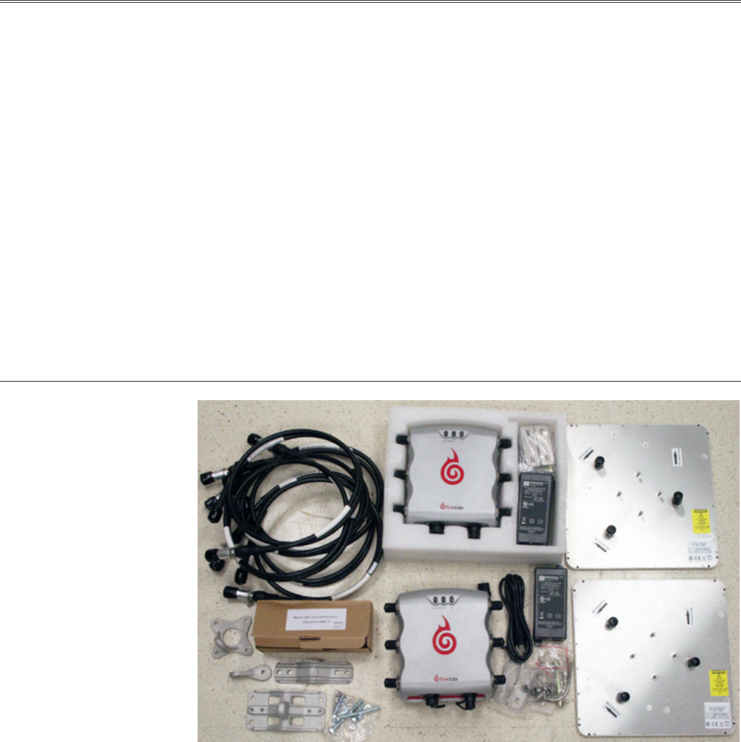
The FWB-205 Kit is shown in Figure 1. Each kit includes two radio modules, two 19-dBi MIMO an-
tennas, RF cables, Ethernet PoE injector/powersupplies, and mounting hardware.
NOTE: The FWB-205 Kit and its two 19 dBi panel antennas are intended for xed (non-mobile),
point-to-point applications only. Any other use is prohibited.
Installation requires these tools:
• 1/2-inch open-end wrench
• 7/16-in open-end wrench
• 3/8-inch open-end wrench
• Phillips screwdriver
• Channel-lock or slip-joint pliers
• RJ-45 crimping tool and male plug
• Waterproong tape or mastic for RF connections.
The assembly must be grounded. If the mast is not already properly grounded, you will need ap-
propriate grounding hardware. Consult local codes.
Figure 1. FWB-205 Kit Contents
The FWB-205 units have three antenna connectors for each radio. Each FWB-205 unit should
be installed with its antenna on a sturdy pole or mast. It does not matter whether you install
the antenna rst or the radio unit rst. In all cases, antennas should be installed by a qualied
professional. Outdoor installations MUST have code-approved grounding and lightning-protection
systems.
Firetide. Reliable Connectivity Anywhere 3 Preliminary Version 2.0
Antenna Installation
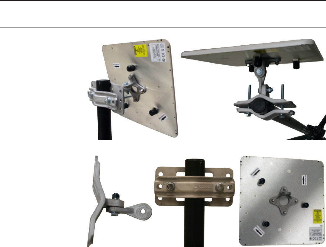
An assembled and mounted antenna is shown in Figure 2. The mounting systems consists of a pole
clamp assembly, a pivot link, and an antenna bracket. These are shown in Figure 3.
Figure 2. Mounted Antenna
Figure 3. Pivot Link; Pole Clamp Assembly; Antenna Bracket
Begin assembly by attaching the pivot link to the pole clamp assembly, as shown at left in Figure
3. Use a at washer under the bolt head, and under the nut use a at washer and lock washer.
Next, attach the pole clamp assembly to the pole, as shown at center in Figure 3. Again, use a at
washer under the bolt heads, and under the nuts use a at washer and lock washer.
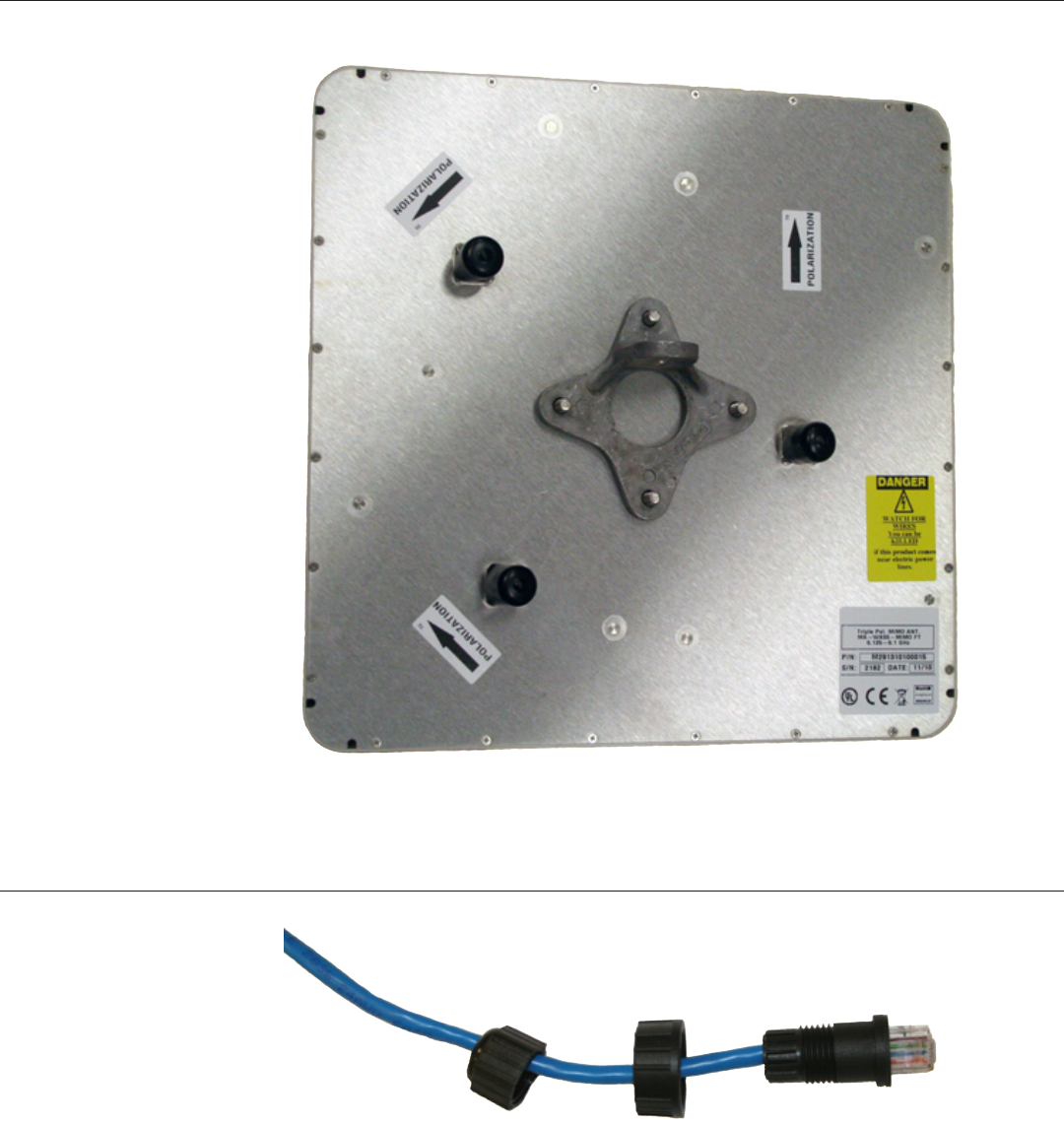
Mount the antenna bracket to the antenna such that the mounting lug is horizontal when the top
of the antenna is up, as shown at right in Figure 3. Antenna polarizations must match between the
two ends of a link.
4 Firetide FWB-205 Wireless Bridge User Guide March 2011
Installing the Radio Unit
The radio unit mounts with a two-piece mounting assembly. One half of the assembly is perma-
nently attached to a pole or wall; the second half, on the radio itself, hooks over the rst.
Figure 4. Two-Piece Radio Mounting Plate Assembly
Hooks (4) Hook Attachments
(4)
Radio Unit with
Mounting Plate
Plate for Pole
or Wall Mount
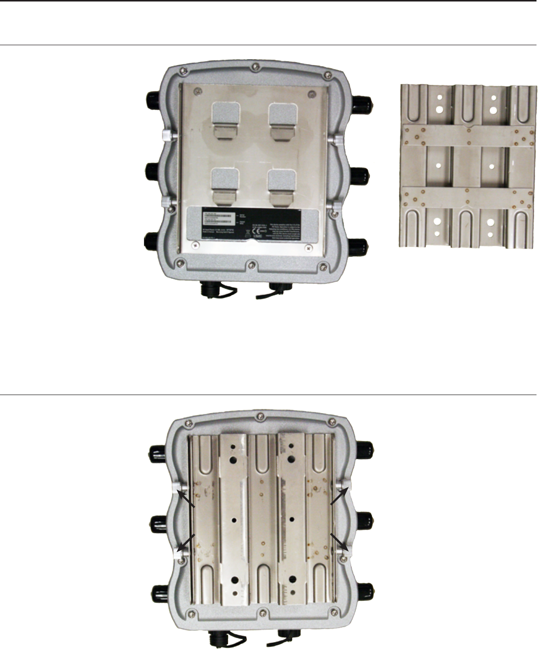
The FWB-205 is shipped with a two-piece mounting plate already attached, as shown in Figure 5.
Loosen the four fasteners, two on each side, to remove the hook-attachment plate. The captive
screws are tight; you will need channel-lock or slip-joint pliers.
Figure 5. Radio and Mounting Plate Assembly, As Shipped
Captive Screws (4)
Firetide. Reliable Connectivity Anywhere 5 Preliminary Version 2.0
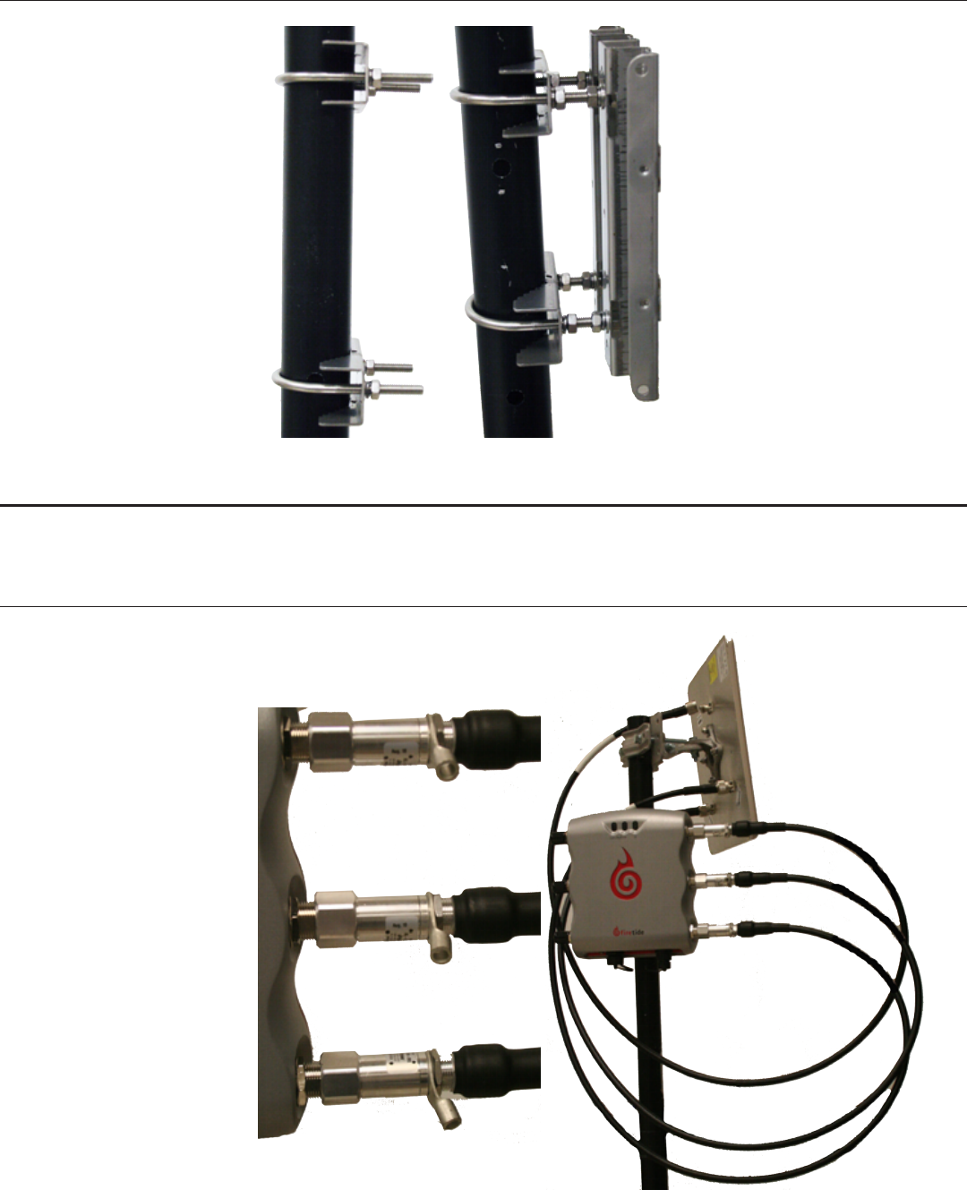
Attach two U-bolt assemblies to the mounting pole, as shown in Figure 6. The U-bolts are large
enough to accomodate large poles; if you are mounitng on a smaller-dialmeter pole, you must
either cut the U-bolts to length or use four additional spacer nutes, as shown at right in Figure 6.
Figure 6. U-Bolt Attachment to Pole, Spacer Nuts on U-Bolts
Now you can hang the radio unit on the bracket, and tighten the four captive screws.
Connecting the Antennas
Connect the radio unit to the antenna using the supplied cables. The cables are equipped with
lightning-arrestor units, and should be installed with the arrrestors connected to the radio unit,
not the antennas. This is shown at left in Figure 7.
Figure 7. Cable-to-Radio Connections; Completed Installation
6 Firetide FWB-205 Wireless Bridge User Guide March 2011
Cable connection pattern is critical. You must use the Radio 2 antenna connectors; these are on
the right side of the unit when viewed from the front. The panel antennas included with the FWB-
205 are ‘handed’; the individual antenna connections on the radio unit must be connected to the
antenna in a specic way, and it is slightly different on each end of the link.
On one end of the link, connect the three antenna leads as shown in red. On the other end, con-
nect them as shown in green. Not that this reverses connections 2 and 3; this preserves matching
antenna polarization
Figure 8. Antenna Connections
11
23
32
The nal step is to fabricate the weatherproof Ethernet connect. Thread the cable as shown, and
then attach it to the FWB-205 radio unit.
Figure 9. Ethernet Cable Fabrication
Firetide. Reliable Connectivity Anywhere 7 Preliminary Version 2.0
Chapter 2. Initial Setup for the FWB-205
Initial Setup & Login
The FWB-205 units are sold in pairs. and each pair has been programmed at the factory to work
with each other. Installation of the devices should only be done by qualied and experienced
personnel. Outdoor installation involves many safety hazards, including electrocution, lightning
strikes, and falls. Please be careful.
In all cases, test and congure the units before mounting it on the pole or mast. Set the two units
up on the bench and apply power. Wait about 1-2 minutes for the units to boot up and establish a
radio connection.
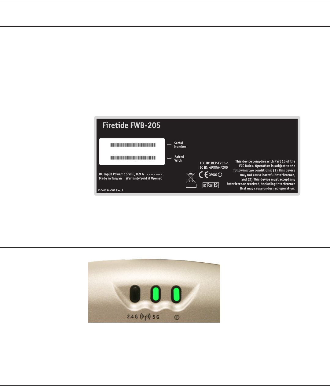
Each unit has a label, as shown, which identies the unit and its partner. Connect your computer
to the power insertion unit which feeds the lower-numbered member of the pair.
MO 3 2 4 0 8 0 6 0 0 0 1 6 7
MO 3 2 4 0 8 0 6 0 0 0 3 9 1
192.168.224.161
192.168.224.162
FWB nodes are paired, or “married”, at the factory. Within each pair, the unit with the lower serial
number is assigned IP address 192.168.224.161, and the unit with the higher serial number is as-
signed IP address 192.168.224.162. You can change these addresses if desired.
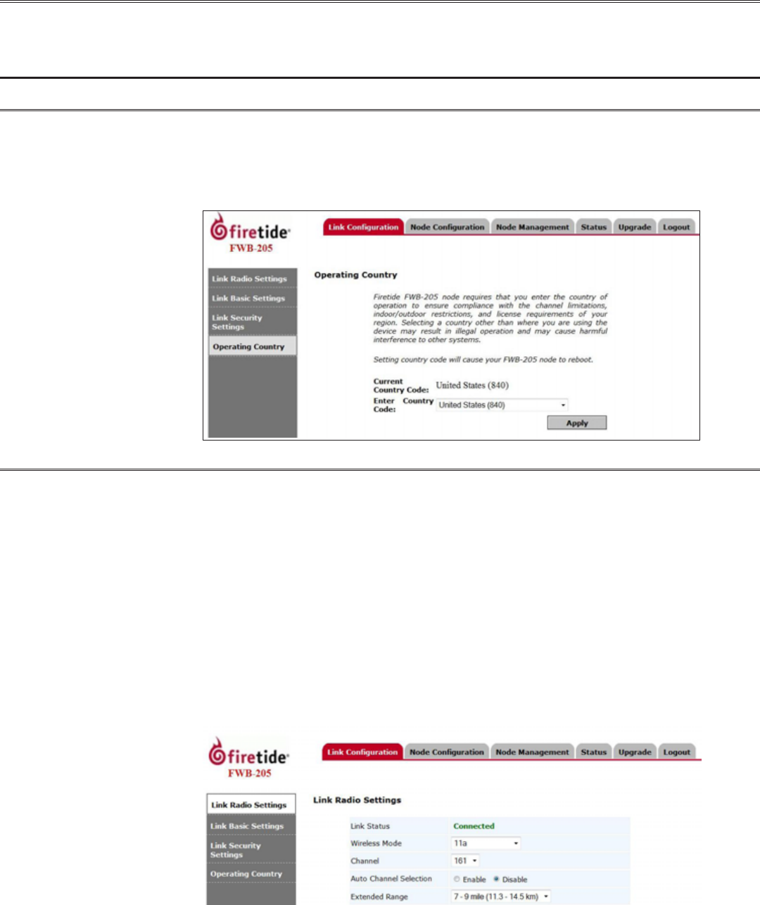
Congure the computer to have an IP address on the subnet 192.168.224.0/24. When you power
up the two units on the bench, they will usually connect. The LEDs should look like .
Figure 10. LED Pattern for Normal Operation
Connect to the unit labeled with the 192.168.224.161 IP address. Point the browser at
https://192.168.224.161. IE8 is the preferred browser, but most other common browsers will also
work. Note: it is a secure web connection (https) not a conventional connection (http).
You will be asked for a login and password; the defaults are admin and retide. You should change
these when you congure the FWB units. Proceed to set the country code.
Website Security Certicate Warning
Website security certicate warnings may occur. Accept Continue with the Website prompts when
they occur.
8 Firetide FWB-205 Wireless Bridge User Guide March 2011
Chapter 3. Radio and System Settings
Radio and System settings include Link Conguration (RF settings), Node Conguration (IP and
network settings), Node Management Settings, Node Status, and Firmware Upgrade commands.
Link Conguration
Operating Country
Firetide FWB-205 nodes require that you enter the country of operation to ensure compliance
with the channel limitations, indoor/outdoor restrictions, and license requirements of your region.
Selecting a country other than where you are using the device may result in illegal operation and
may cause harmful interference to other systems. The node will reboot after you click Apply to set
the country code.
Link Radio Settings
Link Status shows whether or not the two devices connected successfully. If the two nodes did
not connect with each other, you must connect to and point your browser at the second node, at
https://192.168.224.162. Log in as before, and set its country code. The nodes should connect.
If not, check the radio settings on each node, and make sure the two nodes are set to the same
channel and operating mode (a, n, etc).
Conguration options include: Wireless Mode, Channel, Auto Selection of Channel and Extended
Range. Wireless Mode settings include: 11a, 11a static turbo, and 11n-20MHz and 11n-40MHz.
Extended Range can be set from 0 to 9 miles (0 to 14.5 km). Increasing the range setting does not
actually increase the range or power of the radios. Rather, it affects the timing of pauses between
packets. Longer links require longer pauses. Set this parameter to be greater than the path length.
A too-short setting will result in frequent collisions and reduced throughput.
Click Apply to save settings.
Firetide. Reliable Connectivity Anywhere 9 Preliminary Version 2.0
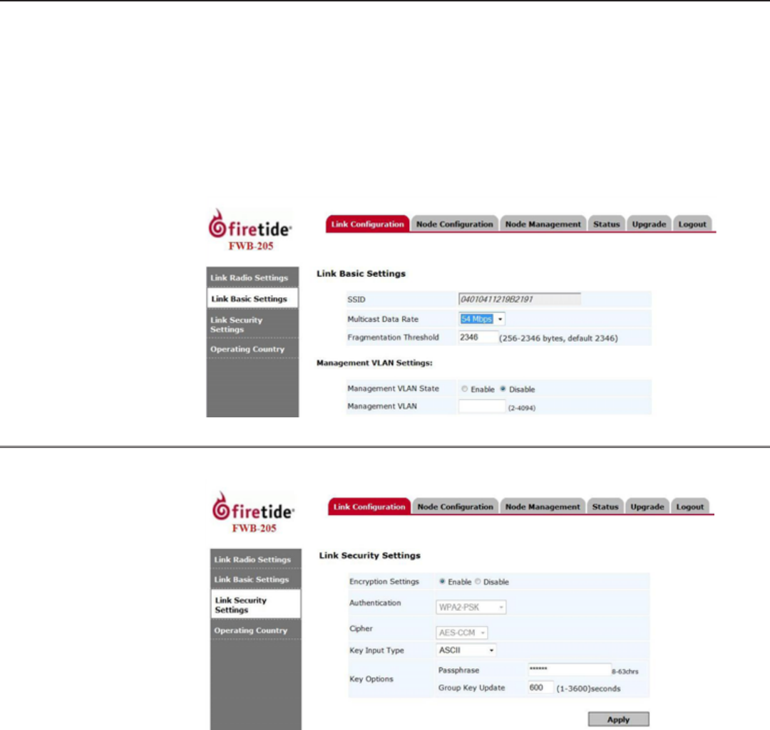
Link Basic Settings
Link Basic Settings include Multicast Data Rate, Fragmentation Threshold, and Management VLAN
Settings.
The multicast data rate can be set from 1 Mbps up to 54 Mbps. Per the original 802.11 standard,
many WiFi systems automaticlly slow down when sending multicast trafc, to maximize the likeli-
hood of all recipients receiving the signal. In a point-to-point conguration this is not necessary,
thus a setting of 54 Mbps is recommended.
The fragmentation threshold is generally best left at the default setting of 2346. Management VLAN
status can be enabled or disabled. If enabled, select the appropriate management VLAN number.
Click Apply to save settings.
Link Security Settings
Link Security Settings provide support for encryption. The default is Enabled, WPA2-PSK.
10 Firetide FWB-205 Wireless Bridge User Guide March 2011
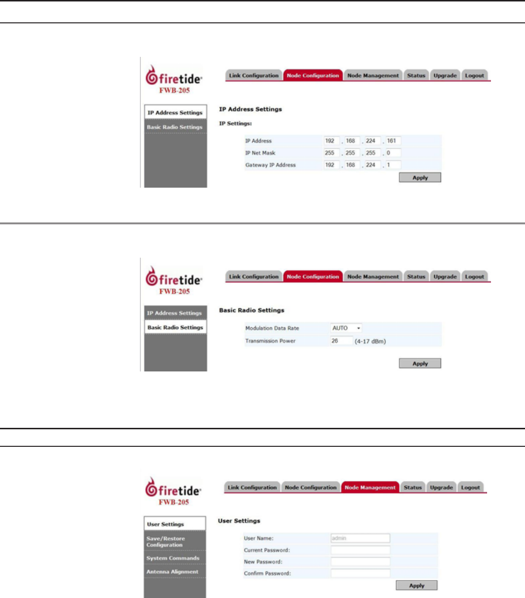
Node Conguration
IP Address Settings
Congure node IP address settings here. Enter the node IP address, IP Net Mask, and Gateway IP
address. Click Apply to save settings.
Basic Radio Settings
Radio settings used by the node are displayed on this page. Node settings for Modulation Data Rate
and Transmission Power can be selected. Click Apply to save settings.
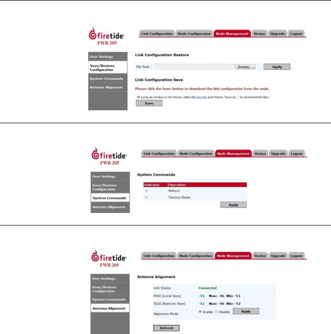
Node Management
User Settings
Congure users with conguration privileges here by adding User Name and Password.
Firetide. Reliable Connectivity Anywhere 11 Preliminary Version 2.0
Save/Restore Conguration
You can save the current link conguration as a le by selecting Save. Nodes can be restored by
using the Restore function to apply a previously-saved le.
System Commands
System Commands let you reboot the node or perform a factory reset. Note that a factory reset will
re-enable the antenna alignment tool, and require you to re-specify the country code.
Antenna Alignment
Antenna alignment settings are available here. Alignment is on by default. To insure maximum
performance, turn off the alignment feature after alignment is complete.
12 Firetide FWB-205 Wireless Bridge User Guide March 2011
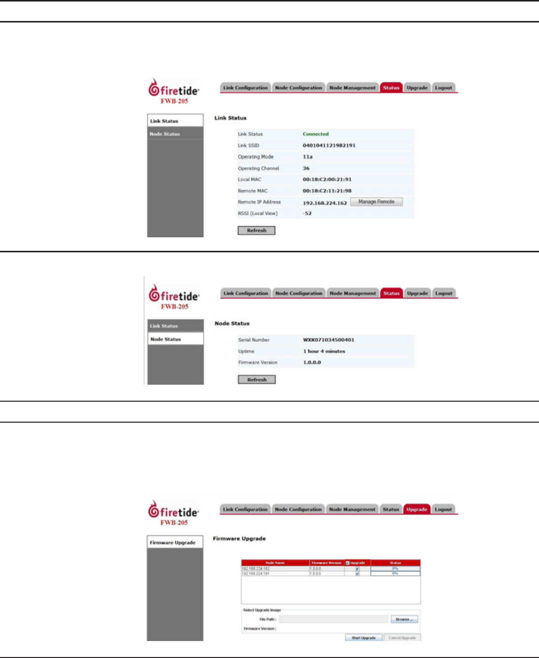
Status
Link Status
Link Status is displayed here. Click Refresh to see the current status. Link status includes current
radio operating mode, RF channel, node MAC addresses, and IP addresses. The Manage Remote but-
ton lets you connect to and manage the remote node, as long as the RF link is up.
Node Status
Node Status is displayed here. Click Refresh to see the current status.
Upgrade
Firmware Upgrade
In order to upgrade rmware, you must have Java installed on your PC. When you begin this pro-
cess, the Java applet will take a moment to load.
Browse to select upgrade image. Click Start Upgrade to begin. Once started the upgrade can be
cancelled by clicking Cancel Upgrade.
Logout
Select the Logout tab to exit from the session.

Firetide. Reliable Connectivity Anywhere 13 Preliminary Version 2.0
Wireless Interface
Model Use
FWB-205 Outdoor, Worldwide, Radio 2: 5 GHz
Bands Frequency (GHz) Restrictions
802.11a
802.11n
5.15-5.25
5.25-5.35
5.725-5.825
4.9-5.090
4.94-4.990
Japan only
US Public Safety
5.470-5.725 ETSI 301.893, U-NII
Bands (GHz) Max TX Power
802.11a 5.725-5.825 UNII-3
802.11n
5.725-5.825 UNII-3
5.470-5.735 UNII
5.25-5.36 UNII-2
5.15-5.25 UNII-1
20 dBm
20 dBm
20 dBm
20 dBm
17 dBm
Supported Data Rates & Standards
• 802.11a 6/9/12/18/24/36/48/54Mbps
• 802.11a Capable of switching to 1⁄4 and 1⁄2 rates for 4.940 –
4.990 GHz Public Safety Band
• 802.11g 6/9/12/18/24/36/48/54Mbps
• 802.11n 6.5/13/19.5/26/65/130 (20MHz LGB)
7.2/14.4/21.7/28.9/72.2/144 (20MHz SGB)
13.5/27/40.5/54/135/270 (40MHz LGB)
15/30/45/60/150/300 (40MHz SGB)
• Network Standards: IEEE 802.11a/d/e/f/h/i/n
• Security: WPA; 64/128/256 w/TKIP, AES
Power
• 48 VDC via DC connecter or 802.3af PoE
Appendix A FWB-205 Specications
Environmental
• Humidity (non-condensing): 10% to 90%
• Storage humidity (non-condensing): 5% to 95%
• Maximum altitude 15,000 feet (4600 meters)
Network Port
• One 10/100/1000 Mbps Ethernet port with weatherproof con-
nector
• IEEE 802.3, 802.3u compliant
• CSMA/CD 10/100/1000 autosense
Enclosure
• Cast aluminum NEMA-4X/IP66 enclosure
• Six N-type antenna connectors
• Weatherproof 48VDC power connector
• Weight: 3.75 lbs (1.7 Kg) with bracket
• Dimensions: 8.2” x 8.6” x 2” (205 x 214 x 100 mm)
Security, Authentication and Encryption
• 802.11i, WPA2
• 40-bit, 104-bit WEP keys
• SSID suppression
Management and Conguration
• Built-in web-based management
• Remote rmware upgrade
Network Ports
• One 10/100/1000 autosense Base-T port
• IEEE 802.3,802.3 at based PoE
Warranty
• Hardware: one year limited warranty
• Software: 90 days limited warranty
Appendix B Reset Procedure
Firetide FWB-205s may be reset to factory parameters. This is useful when returning a unit from
eld service or in recovering a unit you cannot communicate with. To reset a unit, apply power and
wait for the unit to fully boot. This takes 60 to 90 seconds. Use a paperclip to press and hold the
reset button for 15 seconds. Wait for the units to reboot before removing power.
When a unit has been reset, it forgets the country code setting and operates at low power until
the country code is re-established. Units that are already installed in the eld are unlikely to com-
municate with each other after reset, due to the low power setting. You must connect to each unit
in turn and set the country code.

14 Firetide FWB-205 Wireless Bridge User Guide March 2011
Appendix C Regulatory Notices
FCC Part 15 Note
These devices comply with Part 15 of the FCC Rules. Operation is subject to the following two con-
ditions:
• This device may not cause harmful interference.
• This device must accept any interference received, including interference that may cause unde-
sired operation.
FCC Class B Notice
This equipment has been tested and found to comply with the limits for a Class B digital device,
pursuant to Part 15 of the FCC Rules. These limits are designed to provide reasonable protection
against harmful interference in a residential installation. This equipment generates, uses and can
radiate radio frequency energy and, if not installed and used in accordance with the instructions,
may cause harmful interference to radio communications. However, there is no guarantee that
interference will not occur in a particular installation. If this equipment does cause harmful in-
terference to radio or television reception, which can be determined by turning the equipment off
and on, the user is encouraged to try to correct the interference by one or more of the following
measures:
• Reorient or relocate the receiving antenna.
• Increase the separation between the equipment and receiver.
• Connect the equipment into an outlet on a circuit different from that to which the receiver is
connected.
• Consult the dealer or an experienced radio/TV technician for help.
FCC Radiation Exposure
To ensure compliance with the FCC’s RF exposure limits, the antenna used for this transmitter must
be installed to provide a separation distance of at least 76 cm from all persons and must not be
co-located or operated in conjunction with any other antenna or transmitter. Installers and end
users must follow these installation instructions.
Modications
Any modications made to this device that are not approved by Firetide, Inc. may void the author-
ity granted to the user by the FCC to operate this equipment.
Installation
The FWB-205 Kit and its two 19 dBi antennas are intended for xed, point-to-point applications
only. Any other use is prohibited. Antenna(s) for the FWB-205 outdoor unit must be installed by a
qualied professional. Operation of the unit with non-approved antennas is a violation of U.S. FCC
Rules, Part 15.203(c), Code of Federal Regulations, Title 47.
Canadian Compliance Statement
This Class B Digital apparatus meets all the requirements of the Canadian Interference-Causing
Equipment Regulations. Cet appareil numerique de la classe B respecte les exigences du Reglement
sur le material broilleur du Canada.
FWB-205 devices are certied to the requirements of RSS-210 for 2.4 GHz spread spectrum devices.
The use of this device in a system operating either partially or completely outdoors may require the
user to obtain a license for the system according to the Canadian regulations. For further informa-
tion, contact your local Industry Canada ofce.
NCC Statement
一、經型式認證合格之低功率射頻電機,非經許可,公司、商號或使用者均不得擅自變更頻率、加大功率或變更原設計之特性及功能。
二、低功率射頻電機之使用不得影響飛航安全及干擾合法通信;經發現有干擾現象時,應立即停用,並改善至無干擾時方得繼續使用。
前項合法通信,指依電信法規定作業之無線電通信。
低功率射頻電機須忍受合法通信或工業、科學及醫療用電波輻射性電機設 備之干擾。

Appendix D Limited End User Product Warranty
Pursuant to all provisions described herein, Firetide hardware products
and Firetide antennas are warranted for one (1) year from the date
of purchase against defects in the build materials and workmanship.
Firetide does not warrant that the Products will meet any requirements
or specications of any End User Customer. This warranty applies to the
entire Firetide product, including the AC power adapter.
Pursuant to all provisions described herein, Firetide software products
are warranted for ninety (90) days from the date of purchase against
defects in the build materials and workmanship. Firetide also warrants
that the Software will materially conform to the documentation supplied
by Firetide with the Software. In the event that the Software fails to
materially conform to the documentation and an authorized Firetide
reseller is notied in writing of such failure within the warranty period,
Firetide or its reseller shall use commercially reasonable efforts to
promptly correct the nonconformity. Firetide does not warrant that the
use of the Software will be uninterrupted or error free.
The above warranties are void if the alleged defect cannot be veried by
Firetide or if, as determined by Firetide, the product failure was due to
tampering, abuse, misuse, accident, shipping, handling, or storage; or
if the product has been installed, used, or maintained in a manner not
described in the product user manual; or if the product has been altered
in any way; or if product serialization has been altered. Any attempt
to disassemble or repair the product by anyone other than Firetide
immediately voids this warranty.
This warranty applies only to the original End User purchaser of the
product and may not be transferred to any other individual or entity.
The foregoing are the exclusive warranties applicable to the product
including the software, and the exclusive remedy for defects in the
product. Firetide disclaims all other warranties, whether express,
implied, statutory or otherwise, including but not limited to implied
warranties of merchantability, non-infringement or tness for a
particular purpose. Some laws do not allow the exclusion of implied
warranties so to that extent this limitation may not apply to you.
In no event will Firetide be liable for any special, incidental,
consequential, punitive or indirect damages whatsoever (including,
without limitation, damages for loss of prots, business interruption,
loss of information, or other pecuniary loss) arising out of the use or
inability to use the product or the performance, interruption or failure of
the product, irrespective of the cause of action, even if Firetide has been
advised of the possibility of such damages. Firetide’s cumulative liability
for all claims arising out of or in connection with this warranty will not
exceed the amount paid by the original End User purchaser to purchase
the product. The amounts payable for the product are based in part on
these limitations and these limitations shall apply notwithstanding the
failure of essential purpose of any remedy. Some jurisdictions do not
allow the exclusion or limitation of incidental or consequential damages,
so to that extent the above limitations or exclusions may not apply to
you.
By using the product the original End User purchaser agrees to and is
bound by these terms and conditions.
In the event that a product fails to meet this warranty and Firetide’s
authorized reseller is notied in writing of such failure within the
warranty period, Firetide shall, at its own discretion, either repair
the product or replace it with the same or a functionally-equivalent
product free of charge. Replacement products may contain refurbished
materials in whole or in part. Firetide will honor this warranty provided
the product is returned through an authorized Firetide reseller or dealer
with shipping charges prepaid, along with a proof of purchase describing
the original purchase date and product serial numbers if applicable.
The authorized reseller must acquire a Return Materials Authorization
(RMA) number from Firetide prior to returning any product. Firetide does
not accept shipments of defective products without shipping charges
prepaid.
Please contact your Firetide dealer for instructions on returning defective
or damaged products for repair or replacement. Do not return products
to Firetide, Inc. Please keep all original packaging materials in the event
they are needed to return the product for servicing.

© 2010 Firetide, Inc. All rights reserved. Information subject to change without notice. Firetide, HotPort, and HotPoint are registered trademarks of
Firetide, Inc. Reliable connectivity anywhere, HotView, HotView Pro, MeshBridge, and AutoMesh are trademarks of Firetide, Inc.
Firetide, Inc.
140 Knowles Drive
Los Gatos, CA 95032 USA
www.retide.com
+1 408 399 7771