Firmtech FB755AS Embedded Bluetooth Module User Manual FB755DatasheetV103Eng FCC
Firmtech co., Ltd Embedded Bluetooth Module FB755DatasheetV103Eng FCC
Firmtech >
Users Manual
Embedded Bluetooth
Module
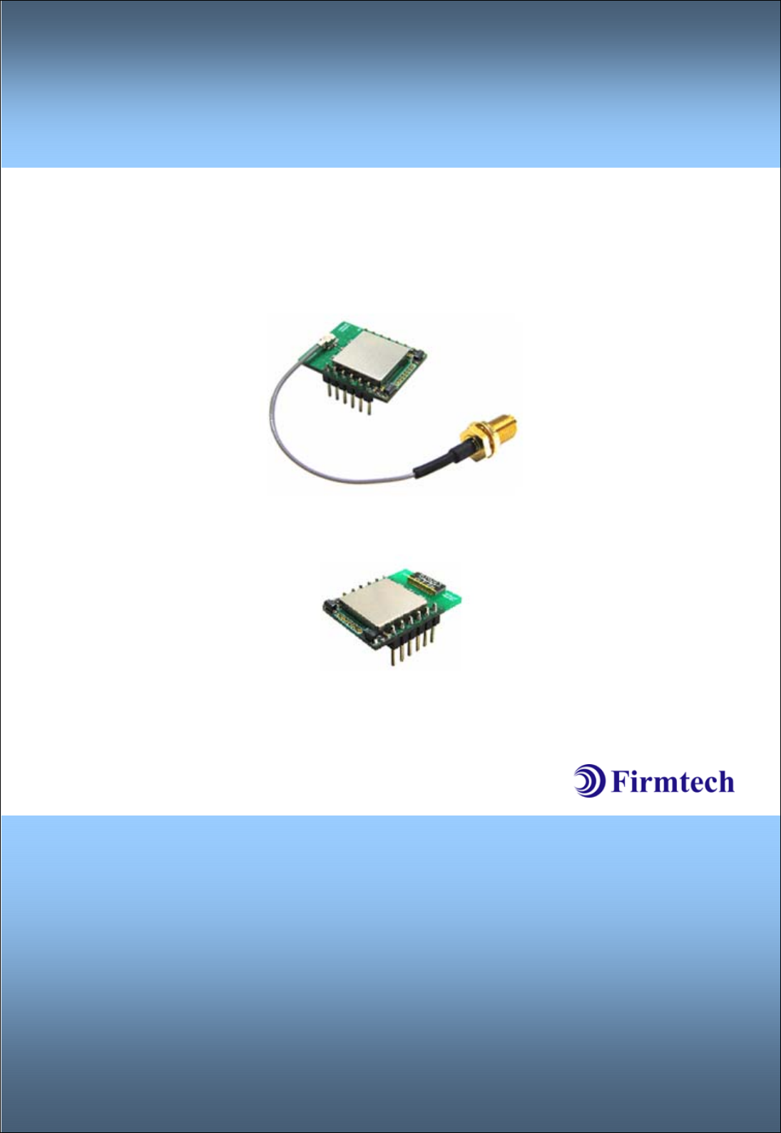
FB755AC & FB755AS
ABOUT FB755AC & FB755AS version 1.0
1:7 Piconet(Point to MultiPoint)
12PINs Header type
Dipole or Chip Antenna
AT Command provided

FB755AC & FB755AS Version 1.0.3
- 2 -
(C) Copyright FIRMTECH Co., Ltd. 2005
All rights reserved
The products and operation descriptions contained herein shall be protected by copyright law.
Any part or whole of products or operation description shall not be copied, reproduced,
translated, nor transformed into readable form by electronic device or machines, without prior
consent in writing by FIRMTECH Co., Ltd.
There might be some misprinting or technical faults in the products and operation description
which are subject to change without prior notice.

FB755AC & FB755AS Version 1.0.3
- 3 -
FIRMTECH Co., Ltd.
Room 720, C Unit of Sigma Officetel, 18,
Kumi Dong, Bundang Ku,
Sungnam City, Kyonggi Do.
Homepage : www.firmtech.co.kr
Marketing Inquiry : contact@firmtech.co.kr
Technical Support Inquiry : techsupport@firmtech.co.kr
Tel : +82-31-719-4812
Fax : +82-31-719-4834
FB755AC & FB755AS Version 1.0.3
- 4 -
What is Bluetooth?
1. Features of Bluetooth
1) Objectives of Bluetooth : To Realize Wireless Communication for Short Distance with Low
Power Consumption, High Reliability, and Low Cost.
2) Frequency in Use: To Use ISM(Industrial, Scientific, Medical) Band which does not require
any permission to use.
- 2.400 – 2.4835 GHz, 79 channels
- 2.465 – 2.4835 GHz, 23 channels (in France)
3) Transmission Rate : 1Mbps
4) Transmission Output : 1mW(10m, Class2), 100mW(100m Class1)
5) Network Configuration : Configured with Master and Slave relation. A Bluetooth unit shall
allow simultaneous connections up to 7 devices (in case of ACL).
6) Reliability : To Guarantee stable wireless communication even under severe noisy
environment through adopting the technique of FHSS (Frequency Hopping Spread Spectrum).
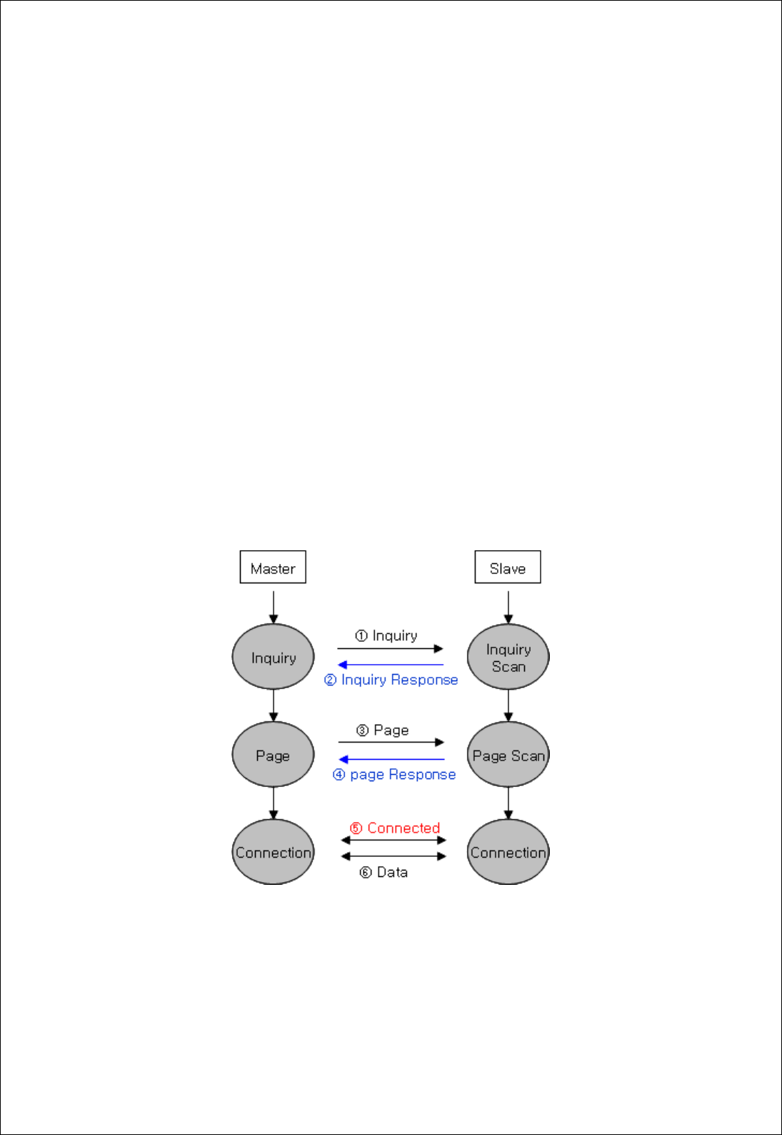
2. Operation of Bluetooth
<Figure 0-1 Operation of Bluetooth>
1) Once the Master will inquire the Slave, the Slave will respond to the inquiry to the Master.
2) When the information of Slave will agree with that of the Master, the interconnection will be
achieved to transmit the data.

FB755AC & FB755AS Version 1.0.3
- 5 -
Products Overview
FB755AC & FB755AS has been developed to replace the previous RS232 Cable system with
wireless mobile communication system to use.
Major Features of FB755AC & FB755AS
1. Bluetooth Specification 2.0 Support
2. Bluetooth Piconets(Point to Multipoint) are configurable up to (max 1:7)
3. Easily applicable to the Product with 12Pins Header type
4. Support AT Command, and capable to control FB755AC & FB755AS by using AT Command.
5. Easy to connect to use with Bluetooth PDA, Bluetooth USB Dongle, etc.
6. Stable Data Transmission / Receipt
※ We request the new users of FB755AC & FB755AS to read the information on this
description carefully before they start to use the products.

FB755AC & FB755AS Version 1.0.3
- 6 -
■ LIST OF CONTENTS
1 PRELIMINARY USAGE OF PRODUCT .................................................................................................... - 7 -
1-1 PRODUCT COMPONENTS......................................................................................................................- 7 -
1-1-1 FB755AC ................................................................................................................................................ - 7 -
1-1-2 FB755AS................................................................................................................................................. - 7 -
2 PERFORMANCE OF PRODUCTS ................................................................................................................ - 8 -
3 CURRENT CONSUMPTION .......................................................................................................................... - 9 -
4 PRODUCT APPEARANCE............................................................................................................................ - 10 -
4-1 FB755AC DIMENSION..............................................................................................................................- 10 -
4-2 FB755AS DIMENSION ..............................................................................................................................- 10 -
4-3 FB755AC PIN ASSIGN ............................................................................................................................- 11 -
4-4 FB755AS PIN ASSIGN ............................................................................................................................- 11 -
5 INTERFACE (PIN CONNECTION).......................................................................................................... - 14 -
5-1WITHOUT FLOW CONTROL .........................................................................................................................- 14 -
5-2 WITH FLOW CONTROL................................................................................................................................- 14 -
5-3 1:N COMMUNICATION................................................................................................................................- 15 -
6 PRELIMINARY PRODUCT COMPONENTS.......................................................................................... - 16 -
7 PC INTERFACE BOARD (JIG BOARD)................................................................................................. - 17 -
8 HOW TO COMPLETE PC CONFIGURATION...................................................................................... - 18 -
8-1 PC CONFIGURATION USING CONGFIG TOOL .........................................................................................- 18 -
8-2 PC CONFIGURATION USING SERIAL COMMUNICATION(HYPER TERMINAL) PROGRAM.............- 22 -
8-2-1 To execute Hyper Terminal............................................................................................................ - 22 -
8-2-2 How to Use PC Configuration Menu........................................................................................... - 26 -

FB755AC & FB755AS Version 1.0.3
- 7 -
1 PRELIMINARY USAGE OF PRODUCT
1-1 PRODUCT COMPONENTS
1-1-1 FB755AC
- FB755AC module
- On-board chip antenna
1-1-2 FB755AS
- FB755AS module
- Stub antenna
- Antenna extension cable
1-1-3 PC Interface Kit
- PC Interface board(Jig board)
- Serial extension cable
- DC Power Adapter
- USB Cable
- CD
If you find any of above components is defective, or not included in the package, please
contact the seller you purchased.

FB755AC & FB755AS Version 1.0.3
- 8 -
2 PERFORMANCE OF PRODUCTS
Part Specification
Bluetooth Spec. Bluetooth Specification 2.0 Support
Communication distance 100 M
Frequency Range 2402 ~ 2480 MHz ISM Band
Sensitivity -83dBm (Typical)
Transmit Power 12dBm (Typical)
FB755AC 27.7 x 20.6 mm
Size FB755AS 27.7 x 20.6 mm
Support Bluetooth Profile GAP, SPP
Input Power 3.3V
Current Consumption 100 mA (Max)
Operating Temperature -20℃ - 50℃
Limit Operating Temperature
Communication Speed 1,200bps – 230,400bps
FB755AC Chip Antenna
Antenna FB755AS Dipole Antenna
Interface UART (TTL Level)
Flow Control RTS, CTS, DTR, DSR support
<Table 2-1 FB755AS & FB755AC Performance>

FB755AC & FB755AS Version 1.0.3
- 9 -
3 CURRENT CONSUMPTION
Current Consumption (mA)
Status MIN MAX AVG
Standby 3 12 8
Inquiry scan & Page scan (Slave) 6 51 28
Page scan (Slave) 6 21 9
Inquiry (Master) 66 69 67
Slave 27 39 29
Connected Master 9 21 12
Slave 33 42 37
Data Transmission Master 30 39 36
Slave 27 42 35
Data Reception Master 30 42 37
Slave 36 42 39
Data Transmission/Reception Master 36 45 40
Slave 6 18 10
Power save Master 5 18 10
<Table 3-1 CURRENT CONSUMPTION>
- TEST CONDITIONS
Baud Rate : 9600 bps, Input Voltage : DC 5V
The power consumption will change depending on transmission speed and volume of data.
FB755AC & FB755AS Version 1.0.3
- 10 -
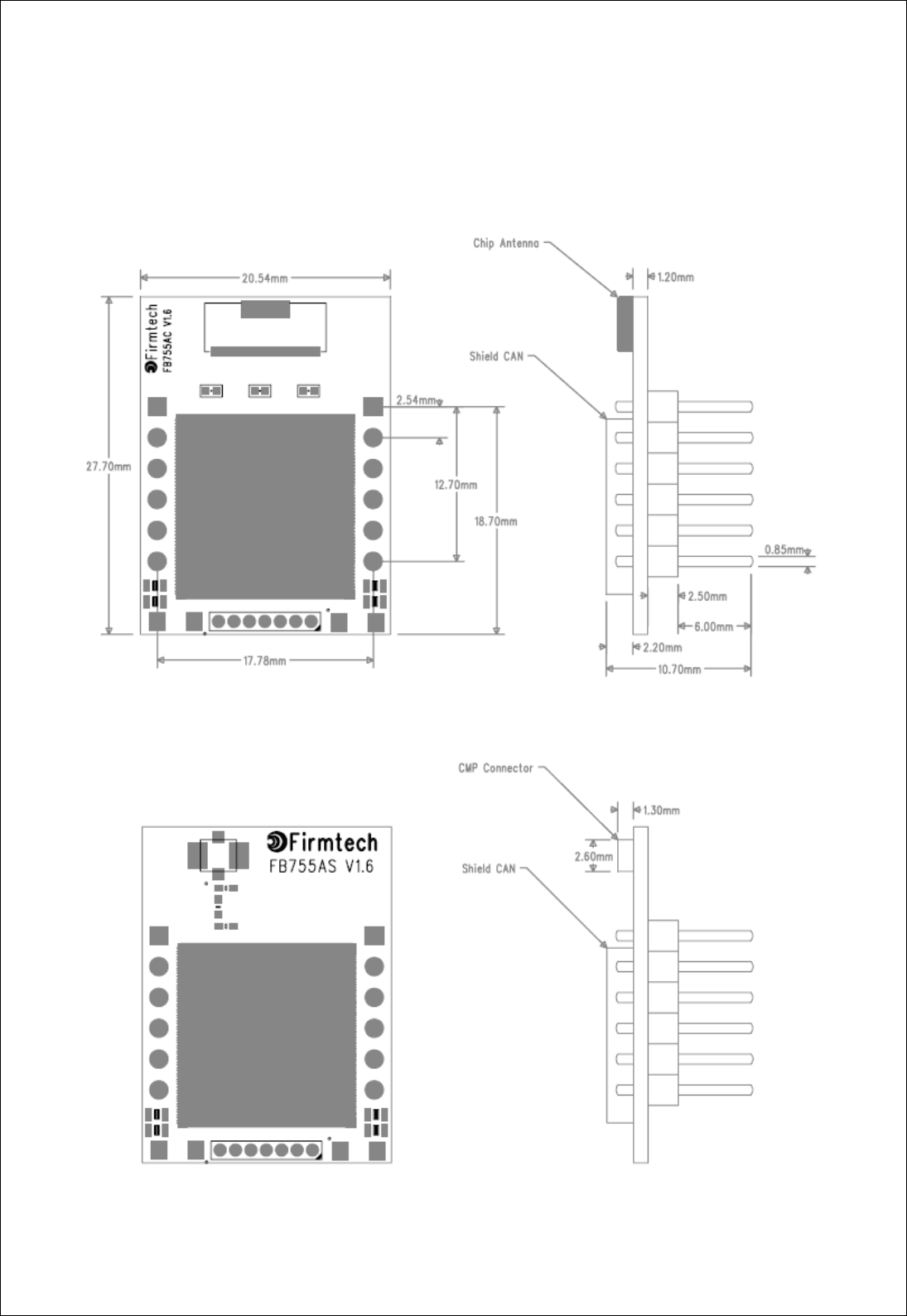
4 PRODUCT APPEARANCE
4-1 FB755AC Dimension
<Figure 4-1 FB755AC Dimension>
4-2 FB755AS Dimension
<Figure 4-2 FB755AS Dimension>
FB755AC & FB755AS Version 1.0.3
- 11 -
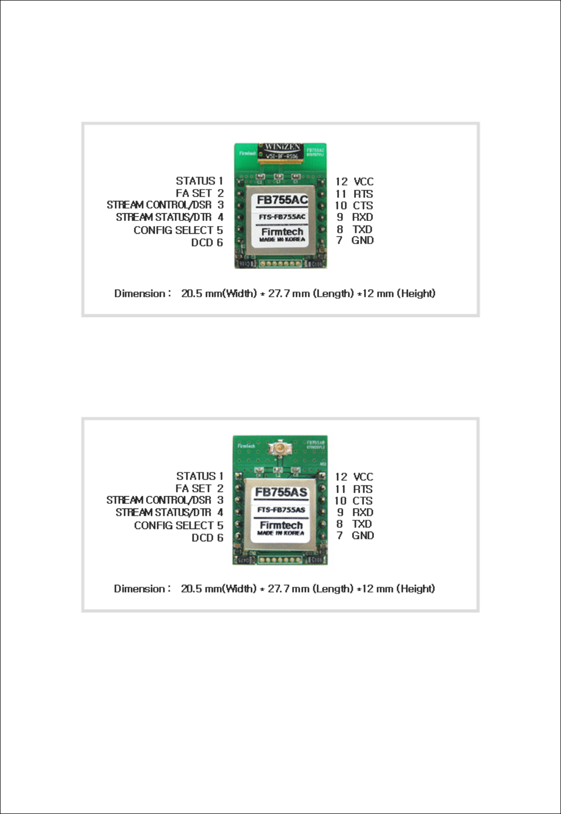
4-3 FB755AC PIN Assign
<Figure 4-3 FB755AC PIN Assign>
4-4 FB755AS PIN Assign
<Figure 4-4 FB755AS PIN Assign>

FB755AC & FB755AS Version 1.0.3
- 12 -
PIN
NO. NAME OF SIGNAL FEATURES INPUT/OUTPUT
DIRECTION
SIGNAL
LEVEL
1 STATUS STATUS LED Output TTL
2 FA SET Factory Reset
Go back default setting Input TTL
Pull-up
STREAM_CONTROL 1:N – Stream Control
3 UART_DSR 1:1 – UART Data Set Ready Input TTL
STREAM_STATUS 1:N – Stream Status
4 UART_DTR 1:1 – UART Data Terminal Ready Output TTL
5 CONFIG_SELECT Configuration Select Input TTL
Pull-down
CONNECT_CHECK 1:N – Connect Check
6 UART_DCD 1:1 - UART Data Carrier Detect Output TTL
7 GND Ground - -
8 UART_TXD UART Transfer Data
Data output Output TTL
9 UART_RXD UART Received Data
Data Input Input TTL
MESSAGE_CONTROL 1:N – Message Control
10 UART_CTS 1:1 - UART Clear To Send Input TTL
MESSAGE_STATUS 1:N – Message Status
11 UART_RTS 1:1 - UART Ready To Send Output TTL
12 VSUP 3.3V DC (VCC) Input
<Table 4-1 Pin Description>
- Hard Reset(Factory Reset)
When the CONFIG_SELECT (No 5 PIN) is HIGH (Pull-up condition), turn the power ON (PC-
Configuration Mode). And then input LOW signal (0 Volt) to FA_SET (No 2 PIN) for more then 2
seconds for the factory reset.
- STATUS port
To be used to monitor the status of FB755AC & FB755AS.
To keep LOW(0V) when the two devices are communicable since the connection between

FB755AC & FB755AS Version 1.0.3
- 13 -
wireless range is smoothly made.
In standby mode for connection with Bluetooth, or connection trial, or searching for around
Bluetooth device will repeat LOW and HIGH.
- UART_CTS/UART_RTS, UART_DTR/UART_DSR
When the flow control is not used, non connection will not affect the operation of FB755AC &
FB755AS.
- STREAM_CONTROL / STREAM_STATUS
The connection is necessarily required for 1:N communication. For 1:1 communication, don’t
need to connect.
- CONNECT_CHECK / UART_DCD
CONNECT_CHECK is used for 1:N communication.
In 1:N communication, if all connection is successful, CONNECT_CHECK (DCD) in SLAVE is
outputted LOW signal. However, if one or more of connections is disconnected, DCD in SLAVE
will be outputted HIGH signal. (Default DCD Output : HIGH)
FB755AC & FB755AS Version 1.0.3
- 14 -
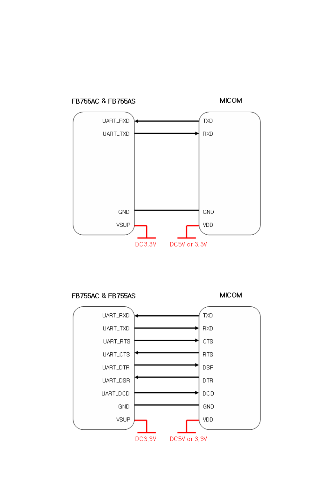
5 INTERFACE (PIN CONNECTION)
5-1Without Flow Control
<Figure 5-1 : Pin Connection without Flow Control >
5-2 With Flow Control
FB755AC & FB755AS Version 1.0.3
- 15 -
<Figure 5-2 : Pin Connection Diagram with Flow Control >
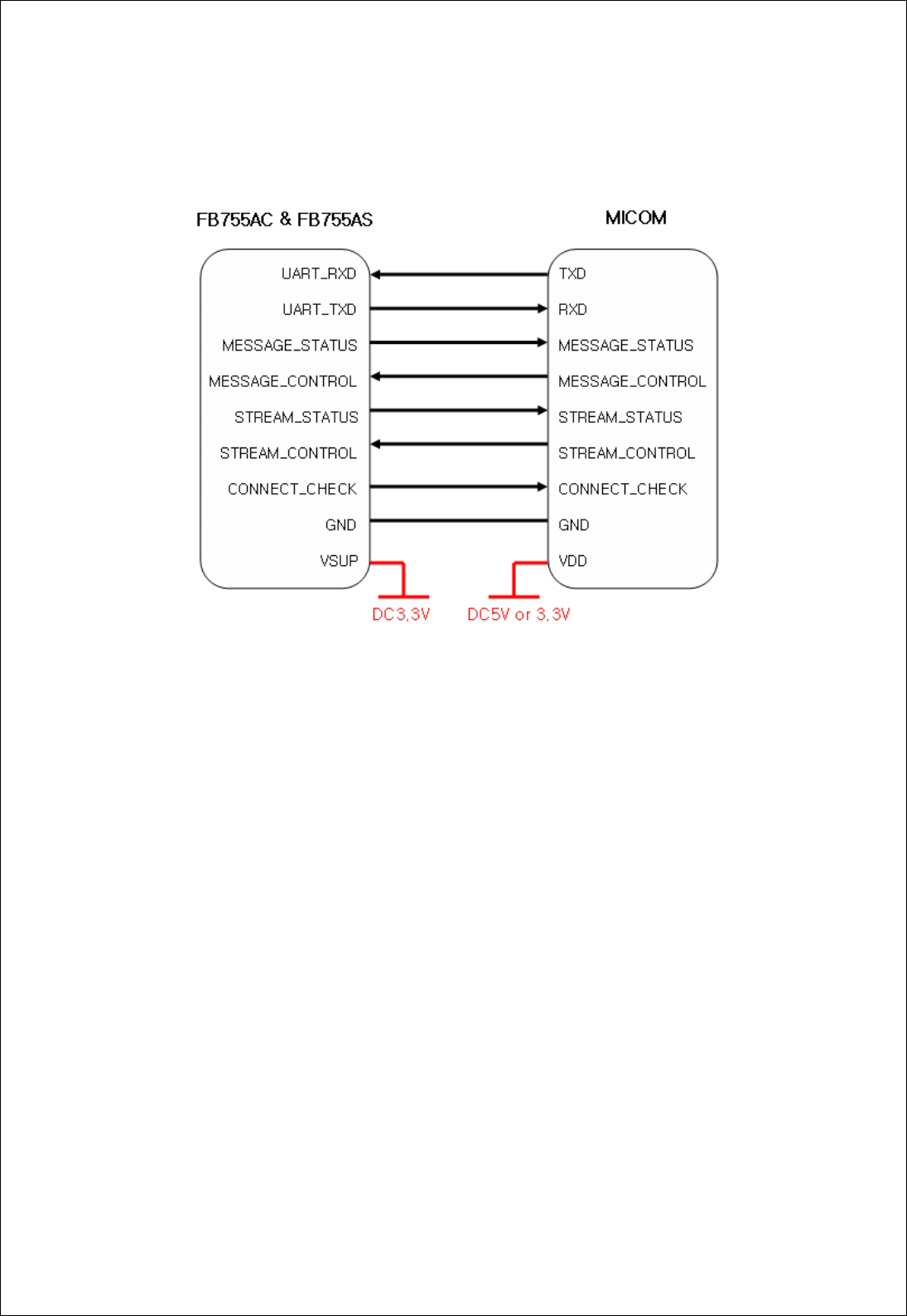
5-3 1:N Communication
<Figure 5-3 : PIN Connection Diagram in 1:N Communication>

FB755AC & FB755AS Version 1.0.3
- 16 -
6 PRELIMINARY PRODUCT COMPONENTS
The preliminary value of product is set as on the <Table 6-1>.
Please be sure of basic set value and so on before using the product.
TYPE SET VALUE
Device Name FB755v.x.x.x
Pin Code(Pass key) BTWIN
Uart(baud rate-data bit-parity bit-stop bit) 9600-8-N-1
ROLE SLAVE
Connection Mode MODE4 (AT command)
Operation Mode MODE0 (1:1 communication)
Debug char 0x02
<Table 6-1 : Preliminary Configuration Setting Value for FB755AC & FB755AS >
To change the configuration set value of FB755AC & FB755AS, connect FB755AC & FB755AS to
the PC using the PC Interface board then, you may change using the PC software (such as
Window Hyper Terminal, FIRMTECH’s PC configuration program). With MICOM, you may
change the set value by using AT command.
Note : For details on the setting change, please refer to 8 How to complete PC Configuration.
FB755AC & FB755AS Version 1.0.3
- 17 -
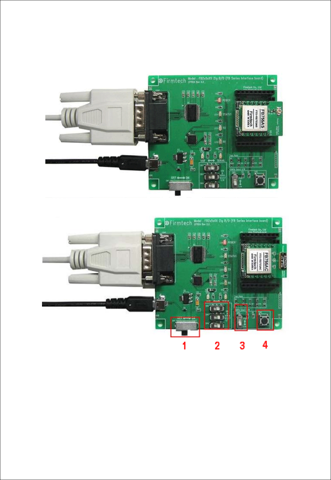
7 PC Interface Board (Jig Board)
1 Power ON/OFF Switch
2 USB / RS232 Interface Select Switch
3 PC Configuration Menu Select Switch
4 FA Set Switch
<Figure 7-1 : FB755AC & FB755AS Interface Board(Jig Board)>
FB755AC & FB755AS Version 1.0.3
- 18 -
8 How to Complete PC Configuration
The following PC Configuration shall be explained on the assumption that FB755AC & FB755AS
is connected with PC Interface Board(Jig board). If it is connected to MICOM, then you can
change the set value by using AT command language with reference to Attachment AT
command language.
Components for PC Configuration
- FB755AC & FB755AS module
- PC Interface Kit
The PC Configuration could be processed with two significant ways.
First one is to use Config tool provided by FIRMTECH Co., Ltd.
Second one is to use serial communication program (Hyper Terminal, minicom) providing OS.
The respective way of setting is as follows.
8-1 PC Configuration using Congfig tool
(1) Connect FB755AC & FB755AS to PC Interface Board, then connect to COM port(Serial port)
of PC.
(2) Set Config Select Switch of PC Interface Board OFF and then turn the power ON.
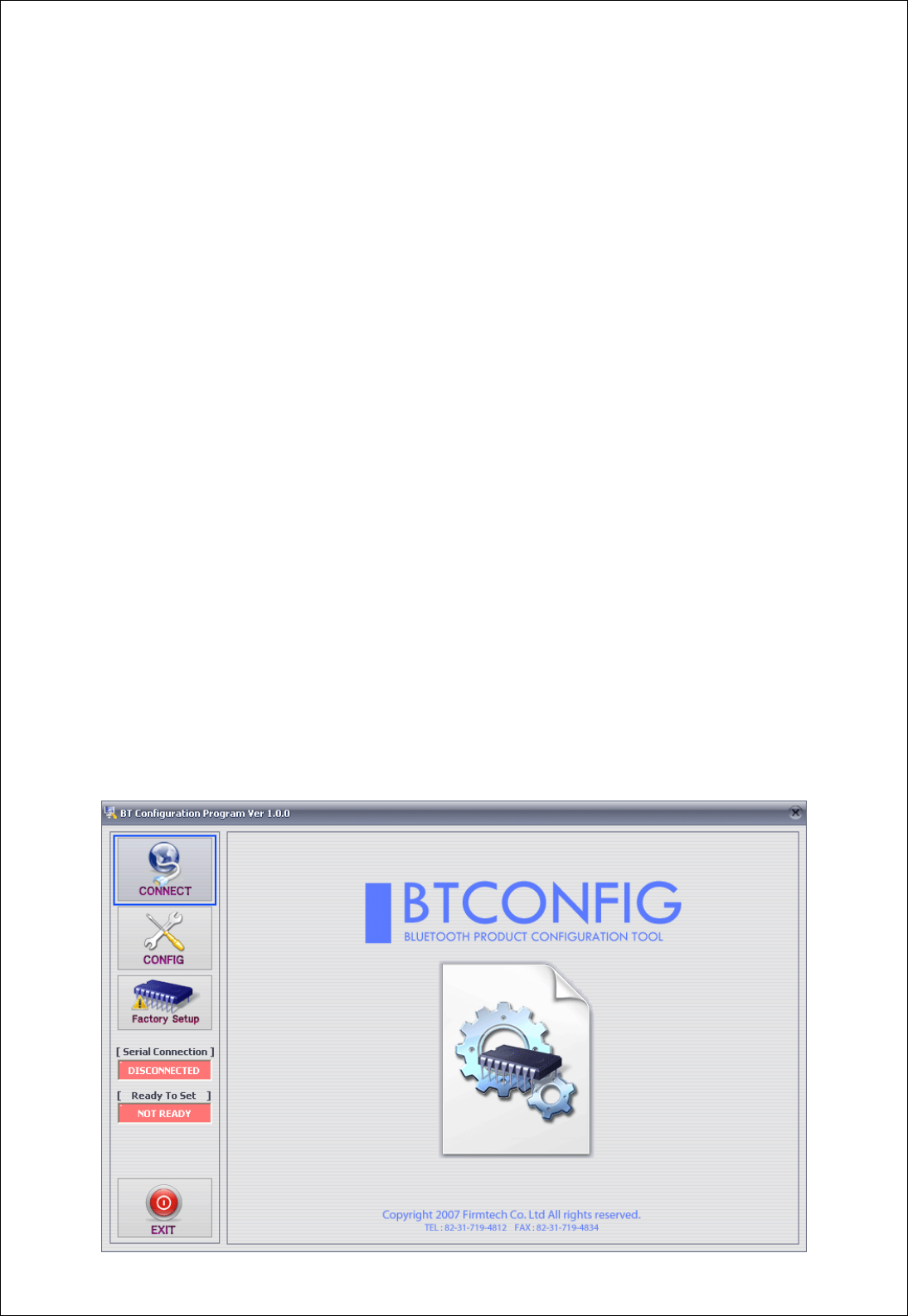
(3) Execute Config tool.
FB755AC & FB755AS Version 1.0.3
- 19 -
<Figure 8-1 : config tool main Display>
(4) Select “CONNECT”(<Figure 8-1> Blue Lined) on the main display.
1 Select Product : Name of Product in Use
2 DEBUG CHAR : Default is 0x02. (Appendix : Refer to details of PC Configuration)
3 Set Serial Port : Default is BAUD RATE : 9600, PARITY BIT : None, STOP BIT : 1
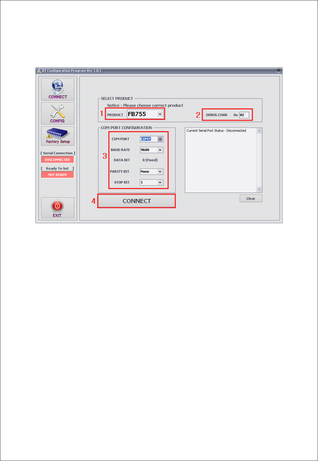
<Figure 8-2 : config tool CONNECT Display>
(5) When the <Figure 8-2> appears, select each selective item of red lines box 1~3, then
press connect (red box line 4) which will change Serial connection, Ready To Set (red lined box
1) into Green as shown on <Figure 8-3>.(The selected value will be certified at the
preliminary setting of product.)
If the color does not change into green, please make sure of the Baud rate of product and re-
execute the config tool.
FB755AC & FB755AS Version 1.0.3
- 20 -
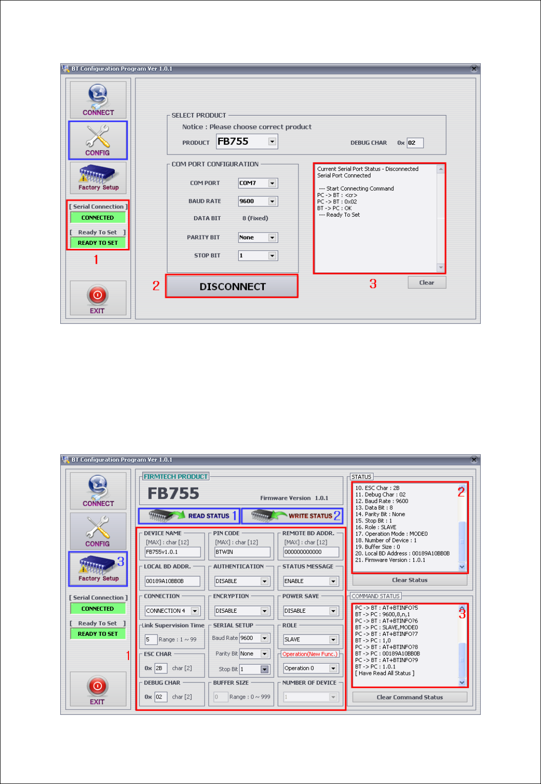
1 Serial Connection, Ready To Set : Show the connection status of Config tool and products
3 Status Message : Display the status of command language in progress
<Figure 8-3 : config tool connection display>
(6) After the product and config tool is connected properly, select CONFIG button(blue lined
box) on Figure<8-3>, display like <Figure 8-4> will comes up to allow to configure the
environment.
1 PC Configuration Window : Allow to select the PC configuration value of the product.

FB755AC & FB755AS Version 1.0.3
- 21 -
2 Status Value : Output the status value with the form of message.
3 Status of Command Language : Since the preliminary operation method is to use AT command, the
progressed AT command language will output in the form of message.
1 READ STATUS Button : To read in the PC configuration set in the product.
2 WRITE STATUS Button : To store the value set in the PC configuration window into the product
3 Factory Setup Button : To reset all the PC configuration value to the factory set value.
<Figure 8-4 : config tool Device Configuration >
(7) To summarize the setting up the config tool, follow the procedures as under.
- To strore the set value upon completion, please be sure to click WRITE STATUS button.
- Click READ STATUS to read in the stored configuration value to certify the they are correct or
not.
- If you want to set as the status first received, click Factory Setup to reset the first received
value.
- Since the config tool was made based on AT command of the product, it is possible to
represent the ongoing command language and its status at the form of status value and
message window.
Note : Please refer to Appendix PC Configuration for detailed explanation.
FB755AC & FB755AS Version 1.0.3
- 22 -
8-2 PC Configuration using Serial Communication(Hyper Terminal) Program
8-2-1 To execute Hyper Terminal
To set up PC configuration using Hyper Terminal, following works will have to be done before
power is authorized to the PC connected with the product.
To accomplish the PC configuration, serial communication program is required. Here Hyper
Terminal will be used for explanation.
(1) Set the Config Select on the PC Interface Board (Jig Board) ON.
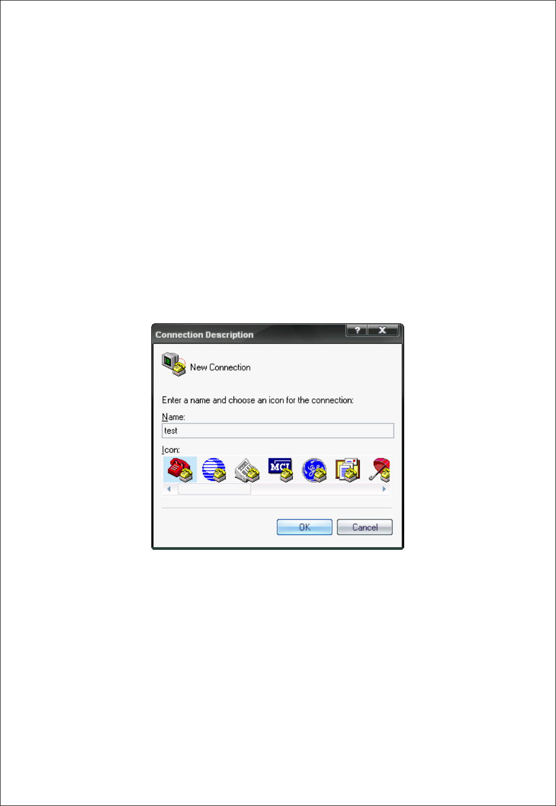
(2) Execute in the order of [start]Æ[All Programs]Æ[Accessories]Æ[Communications]Æ
[Hyper Terminal], then connection window will appear on which enter appropriate name and
click.
<Figure 8-5 Set Up Window 1 of Hyper Terminal>
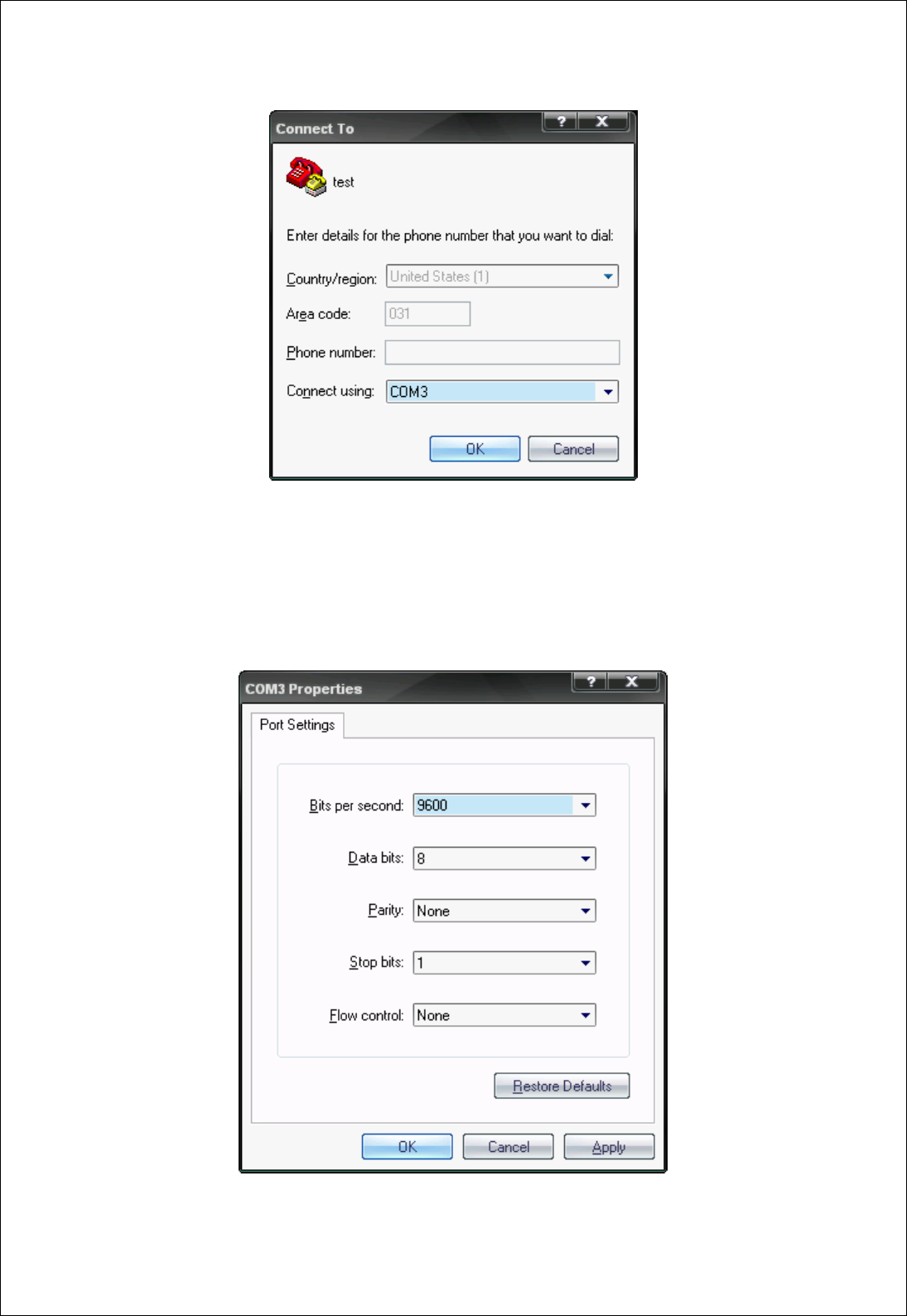
(3) When the <Figure 8-6> comes up, select the COM port connected to FB755AC & FB755AS,
and clicks the Acknowledge button.
FB755AC & FB755AS Version 1.0.3
- 23 -
<Figure 8-6 Hyper Terminal Set Up Window 2>
(4) When Registration Information Window comes up as on <Figure 8-7>, select Bit per
second : 9600, Data bit : 8, Parity : none, Stop bit : 1, Flow control : none, which will
execute Hyper Terminal.
<Figure 8-7 Hyper Terminal Set Up Window 3>
FB755AC & FB755AS Version 1.0.3
- 24 -
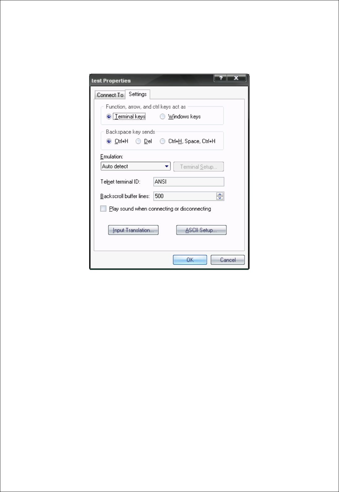
(5) Basically, the Hyper Terminal does not show the entered character. To make sure of the
entered character, select [File]Æ[Properties] on the Menu, then registration information
window will appear shown as on <Figure 8-8>, click the ASCII Setup button.
<Figure 8-8 Hyper Terminal Set Up Window 4>
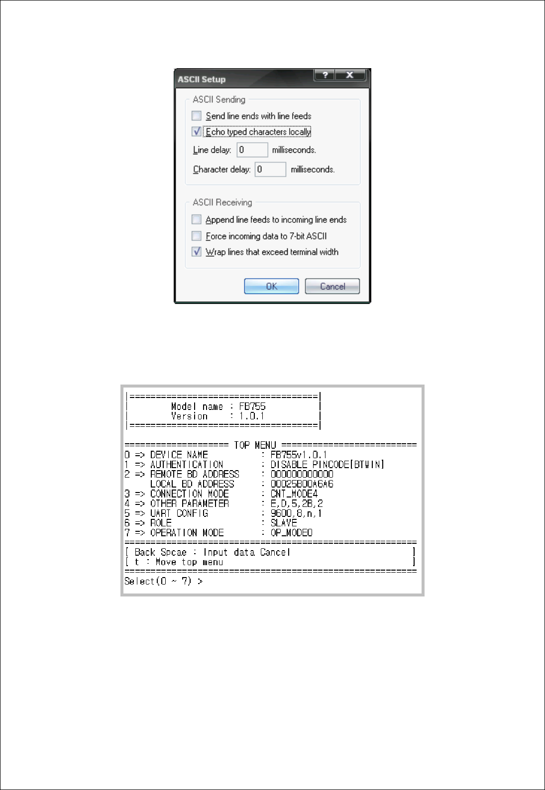
(6) As shown on <Figure 8-9>, “Check Echo typed characters locally” and come out
pressing the acknowledge button. Now the Hyper Terminal program setting procedure is
completed to use PC Configuration.
FB755AC & FB755AS Version 1.0.3
- 25 -
<Figure 8-9 : Hyper Terminal Setting Up Window5>
(7) If power is authorized on the Interface Board, the menu as shown on <Figure 8-10> will be
output on the Hyper Terminal.
<Figure 8-10 : PC Configuration Menu>

FB755AC & FB755AS Version 1.0.3
- 26 -
8-2-2 How to Use PC Configuration Menu
The user will select the menu want to change. To select the menu, you may just select the
number given on the left side.
For example : To change “DEVICE NAME”, enter : [“0”]Æ[Enter]
Note : At <Figure 8-10> condition, Pressing Reset button for more than 2 seconds will reset
all the configured values to the initial status (factory preset status).
Following is the order to use the menu.
(1) The execution will only be executed by pressing the “Enter” key.
(2) The small character “t” will always move to be positioned at upper side of the menu.
(3) To move menu, use the number in the end of left side. Please be sure to “Enter” key upon
completion of input.
(4) “←” key is used to delete the entered character currently.
(5) If the entered character is unreadable or is not supported at the appropriate menu, “Retry
>” message will be output.
(6) If the input message is more than 12 characters, “Overflow buffer” message will be output
and then “Retry >” message appeared as well.
Upon completion of all PC configuration, turn off the Interface Board, switch the
Config Select switch OFF, and turn the power ON, which will start the Bluetooth to
operate normally.
Note : Please refer to Appendix A PC Configuration for the detailed description on the
configuration value.

FB755AC & FB755AS Version 1.0.3
- 27 -
Regulatory Compliance
FCC compliance Information
This device complies with part 15 of FCC Rules.
Operation is subject to the following two conditions:
1. This device may not cause harmful interference received.
2. This device must accept any interference received.
Including interference that may cause undesired operation.
FCC WARNING
This equipment may generate or use radio frequency energy. Changes or modifications to this
equipment may cause harmful interference unless the modifications are expressly approved in
the instruction manual. The user could lose the authority to operate this equipment if an
unauthorized change or modification is made.
A separation between the user’s the antenna be at least 20cm and a prohibition that it can not
be co-located with other transmitter.
To satisfy FCC exterior labeling requirements, the following text must be placed on the exterior
Of the end product.
Contains Transmitter Module FCC ID: U8D-FB755AS
CAUTION: This device and it’s antenna(s) must not be co-located or operated in conjunction
with any other antenna or transmitter. End users cannot modify this transmitter device. Any
Unauthorized modification could void the user’s authority to operate this device.
Here by, firmtech Co., LTD. Declares that this FB755AS is in compliance with the essential
requirements and other relevant provisions of directive 1999/5/EC.